EIS-0486: Final Environmental Impact Statement (Summary)
88
ENVIRONMENTAL IMPACT STATEMENT SUMMARY PLAINS & EASTERN CLEAN LINE TRANSMISSION PROJECT DOE/EIS-0486 Final U.S. DEPARTMENT OF ENERGY Office of Electricity Delivery and Energy Reliability Washington, DC October 2015
Transcript of EIS-0486: Final Environmental Impact Statement (Summary)
E N V I R O N M E N T A L I M P A C T S T A T E M E N T S U M M A R Y
PLAINS & EASTERN CLEAN LINE TRANSMISSION PROJECT
DOE/EIS-0486
Final
U.S. DEPARTMENT OF ENERGYOffice of Electricity Delivery and Energy ReliabilityWashington, DC
October 2015

This page intentionally left blank.
SUMMARY
PLAINS & EASTERN FINAL ENVIRONMENTAL IMPACT STATEMENT S-i
COVER SHEET RESPONSIBLE FEDERAL AGENCY: U.S. Department of Energy (DOE), Office of Electricity Delivery and Energy Reliability
COOPERATING AGENCIES: Natural Resources Conservation Service, Tennessee Valley Authority, U.S. Army Corps of Engineers, U.S. Bureau of Indian Affairs, U.S. Environmental Protection Agency, U.S. Fish and Wildlife Service
TITLE: Plains & Eastern Clean Line Transmission Line Project Final Environmental Impact Statement (EIS) (DOE/EIS-0486)
LOCATION: Texas, Oklahoma, Arkansas, and Tennessee: counties in Texas—Hansford, Ochiltree, and Sherman; counties in Oklahoma—Beaver, Cimarron, Creek, Garfield, Harper, Kingfisher, Lincoln, Logan, Major, Muskogee, Okmulgee, Payne, Sequoyah, Texas, and Woodward; counties in Arkansas—Cleburne, Conway, Crawford, Cross, Faulkner, Franklin, Jackson, Johnson, Mississippi, Poinsett, Pope, Van Buren, and White; and counties in Tennessee—Shelby and Tipton.
CONTACTS: For additional information on this Final EIS contact:
Dr. Jane Summerson, National Environmental Policy Act (NEPA) Document Manager on behalf of the Office of Electricity Delivery and Energy Reliability U.S. Department of Energy DOE NNSA, Post Office Box 5400 Building 391 Kirtland Air Force Base East Albuquerque, NM 87185 Telephone: (505) 845-4091 [email protected]
For general information on the DOE NEPA process, please write or call:
Ms. Carol M. Borgstrom, Director Office of NEPA Policy and Compliance, GC-54 U.S. Department of Energy 1000 Independence Ave, SW Washington, DC 20585 [email protected] Telephone: (202) 586-4600 or Leave a message at (800) 472-2756
ABSTRACT: In June 2010, DOE, acting through the Southwestern Power Administration and the Western Area Power Administration, both power marketing administrations within DOE, issued Request for Proposals for New or Upgraded Transmission Line Projects under Section 1222 of the Energy Policy Act of 2005 (EPAct; 42 United States Code [USC] § 16421; 75 Federal Register 32940; June 10, 2010). In response to the request for proposals (RFP),
SUMMARY
PLAINS & EASTERN S-ii FINAL ENVIRONMENTAL IMPACT STATEMENT
Clean Line Energy Partners LLC of Houston, Texas, the parent company of Plains and Eastern Clean Line LLC and Plains and Eastern Clean Line Oklahoma LLC (collectively referred to as Clean Line or the Applicant) submitted a proposal to DOE in July 2010 for the Plains & Eastern Clean Line Project. In August 2011, Clean Line modified the proposal and subsequently submitted additional information (referred to as the Part 2 Application) in January 2015 at DOE’s request. DOE is the lead federal agency for the preparation of this EIS (or Plains & Eastern EIS), which examines the potential environmental impacts from Clean Line’s proposed Project (also referred to as the Applicant Proposed Project) and the range of reasonable alternatives. DOE has prepared the EIS pursuant to NEPA (42 USC § 4321 et seq.), the Council on Environmental Quality NEPA regulations (40 Code of Federal Regulations [CFR] Parts 1500 through 1508), and the DOE NEPA implementing regulations (10 CFR Part 1021). DOE’s purpose and need for agency action is to implement Section 1222 of the EPAct. To that end, DOE needs to decide whether and under what conditions it would participate in the Applicant Proposed Project.
The Applicant Proposed Project would include an overhead ±600-kilovolt (kV) high voltage direct current (HVDC) electric transmission system and associated facilities with the capacity to deliver approximately 3,500 megawatts primarily from renewable energy generation facilities in the Oklahoma and Texas Panhandle regions to load-serving entities in the Mid-South and Southeast United States via an interconnection with the Tennessee Valley Authority electrical grid in Tennessee. Major facilities associated with the Applicant Proposed Project consist of converter stations in Oklahoma and Tennessee; an approximate 720-mile, ±600kV HVDC transmission line; an alternating current collection system; and access roads. Pursuant to NEPA, DOE has identified and analyzed potential environmental impacts for the range of reasonable alternatives in addition to the Applicant Proposed Project. These alternatives include an Arkansas converter station and alternative routes for the HVDC transmission line.
PUBLIC COMMENTS: The Final EIS1 considers comments submitted on the Draft EIS, including those submitted during the public comment period that began on December 19, 2014, and ended on April 20, 2015, after an extension to the original 90-day comment period. Late comments have been considered to the extent practicable. During the comment period, DOE held 15 public hearings in Oklahoma, Texas, Arkansas, and Tennessee. Approximately 950 comment documents (including several email and letter campaigns) were received during the public comment period. In addition, approximately 270 commenters spoke at the 15 public hearings. The primary topics raised include, but are not limited to, easement acquisition and property rights, routing issues, and potential health effects associated with electromagnetic fields.
1 This Final EIS was revised to incorporate new information gathered since the issuance of the Draft EIS, including updated
resource-specific analytical data as well as information received from commenters on the Draft EIS. Vertical bars in the margins of the pages of the Final EIS indicate where revisions, including deletions, were made.
SUMMARY
PLAINS & EASTERN FINAL ENVIRONMENTAL IMPACT STATEMENT S-iii
Contents
S.1. Introduction .............................................................................................................................. S-1
S.2. Department of Energy’s Purpose and Need ........................................................................... S-2 S.2.1 Section 1222 of the EPAct .............................................................................................................................. S-2
S.3. Clean Line’s Goals and Objectives ....................................................................................... S-17
S.4. Interagency Coordination and Public Participation ............................................................. S-17 S.4.1 Interagency Coordination .............................................................................................................................. S-17
S.4.1.1 Bureau of Indian Affairs ............................................................................................................... S-18 S.4.1.2 Natural Resources Conservation Service .................................................................................... S-18 S.4.1.3 Tennessee Valley Authority ......................................................................................................... S-18 S.4.1.4 U.S. Army Corps of Engineers .................................................................................................... S-18 S.4.1.5 U.S. Environmental Protection Agency ....................................................................................... S-19 S.4.1.6 U.S. Fish and Wildlife Service ..................................................................................................... S-19
S.4.2 Public Participation ........................................................................................................................................ S-20
S.5. Project Description and Alternatives .................................................................................... S-21 S.5.1 DOE Proposed Action ................................................................................................................................... S-21 S.5.2 Applicant Proposed Project Description ........................................................................................................ S-21
S.5.2.1 Converter Stations and Other Terminal Facilities ........................................................................ S-21 S.5.2.2 HVDC Transmission Line ............................................................................................................ S-22 S.5.2.3 AC Collection System .................................................................................................................. S-23 S.5.2.4 Access Roads ............................................................................................................................. S-33 S.5.2.5 Easements and Property Rights .................................................................................................. S-33 S.5.2.6 Project Construction .................................................................................................................... S-33 S.5.2.7 Operations and Maintenance ...................................................................................................... S-37 S.5.2.8 Decommissioning ........................................................................................................................ S-37
S.5.3 Alternatives ................................................................................................................................................... S-37 S.5.3.1 No Action Alternative ................................................................................................................... S-37 S.5.3.2 Applicant Proposed Route ........................................................................................................... S-37
S.5.3.2.1 Region 1 (Oklahoma Panhandle) ........................................................................... S-38 S.5.3.2.2 Region 2 (Oklahoma Central Great Plains)............................................................ S-38 S.5.3.2.3 Region 3 (Oklahoma Cross Timbers)..................................................................... S-39 S.5.3.2.4 Region 4 (Arkansas River Valley) .......................................................................... S-40 S.5.3.2.5 Region 5 (Central Arkansas) .................................................................................. S-41 S.5.3.2.6 Region 6 (Cache River, Crowley’s Ridge Area, and St. Francis Channel) ............. S-42 S.5.3.2.7 Region 7 (Arkansas Mississippi River Delta and Tennessee)................................ S-42
S.5.3.3 DOE Alternatives ......................................................................................................................... S-43 S.5.3.3.1 Arkansas Converter Station ................................................................................... S-43 S.5.3.3.2 HVDC Alternative Routes ...................................................................................... S-44
S.5.3.4 Alternatives Considered but Eliminated from Detailed Analysis .................................................. S-47 S.5.3.4.1 Alternative Transmission Line Routes.................................................................... S-47 S.5.3.4.2 Underground HVDC Transmission Line ................................................................. S-48 S.5.3.4.3 Local Generation and Distribution .......................................................................... S-49 S.5.3.4.4 Energy Conservation Programs ............................................................................. S-49
SUMMARY
PLAINS & EASTERN S-iv FINAL ENVIRONMENTAL IMPACT STATEMENT
S.5.4 Connected Actions ........................................................................................................................................ S-49 S.5.4.1 Wind Energy Generation ............................................................................................................. S-49 S.5.4.2 Related Substation and Transmission Upgrades ........................................................................ S-50
S.5.5 Agency Preferred Alternative ........................................................................................................................ S-51 S.5.5.1 Participation in the Applicant Proposed Project ........................................................................... S-52
S.5.5.1.1 Oklahoma Converter Station and AC Interconnection ........................................... S-52 S.5.5.1.2 Tennessee Converter Station and AC Interconnection .......................................... S-53 S.5.5.1.3 AC Collection System ............................................................................................ S-53 S.5.5.1.4 Arkansas Converter Station and AC Interconnection ............................................. S-53 S.5.5.1.5 HVDC Transmission Line Routes .......................................................................... S-54
S.6. Potential Impacts ................................................................................................................... S-56 S.6.1 Direct and Indirect Impacts............................................................................................................................ S-56
S.6.1.1 Analysis Methodology ................................................................................................................. S-56 S.6.1.2 Agricultural Resources ................................................................................................................ S-59 S.6.1.3 Air Quality and Climate Change .................................................................................................. S-60 S.6.1.4 Electrical Environment ................................................................................................................. S-61 S.6.1.5 Environmental Justice ................................................................................................................. S-63 S.6.1.6 Geology, Paleontology, Minerals, and Soils ................................................................................ S-63 S.6.1.7 Groundwater................................................................................................................................ S-65 S.6.1.8 Health, Safety, and Intentional Destructive Acts ......................................................................... S-66 S.6.1.9 Historic and Cultural Resources .................................................................................................. S-67 S.6.1.10 Land Use ..................................................................................................................................... S-68 S.6.1.11 Noise ........................................................................................................................................... S-70 S.6.1.12 Recreation ................................................................................................................................... S-71 S.6.1.13 Socioeconomics .......................................................................................................................... S-72 S.6.1.14 Special Status Wildlife and Fish, Aquatic Invertebrate, and Amphibian Species ........................ S-73
S.6.1.14.1 Special Status Terrestrial Wildlife .......................................................................... S-73 S.6.1.14.2 Special Status Fish, Aquatic Invertebrate, and Amphibian Species ...................... S-74
S.6.1.15 Surface Water ............................................................................................................................. S-75 S.6.1.16 Transportation ............................................................................................................................. S-76 S.6.1.17 Vegetation Communities and Special Status Plant Species........................................................ S-78 S.6.1.18 Visual Resources ........................................................................................................................ S-79 S.6.1.19 Wetlands, Floodplains, and Riparian Areas ................................................................................ S-80 S.6.1.20 Wildlife, Fish, and Aquatic Invertebrate Species ......................................................................... S-82
S.6.1.20.1 Wildlife ................................................................................................................... S-82 S.6.1.20.2 Fish and Aquatic Invertebrate Species .................................................................. S-83
S.6.2 Summary of Impacts from Connected Actions .............................................................................................. S-84 S.6.2.1 Wind Energy Generation ............................................................................................................. S-84 S.6.2.2 Related Substation and Transmission Upgrades ........................................................................ S-84
S.6.3 Summary of Cumulative Impacts .................................................................................................................. S-85
S.7. Conclusions ........................................................................................................................... S-86 S.7.1 Major Conclusions ......................................................................................................................................... S-86 S.7.2 Issues to be Resolved ................................................................................................................................... S-87
SUMMARY
PLAINS & EASTERN FINAL ENVIRONMENTAL IMPACT STATEMENT S-v
Tables
Table S-1: Counties Potentially Affected by the Applicant Proposed Route ............................................................ S-23
Table S-2: Counties Potentially Crossed by the AC Collection System Routes ...................................................... S-24
Table S-3: Counties Potentially Affected by HVDC Alternative Routes ................................................................... S-44
Figures Presented in Text
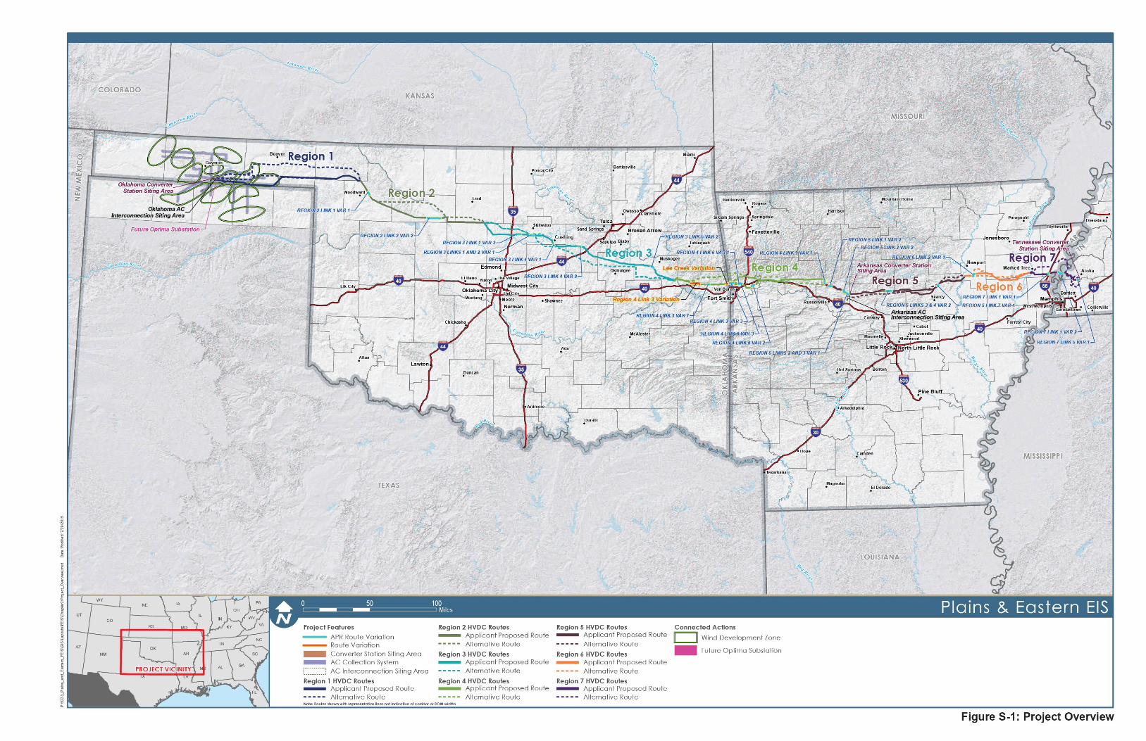
Figure S-1: Project Overview ...................................................................................................................................... S-3
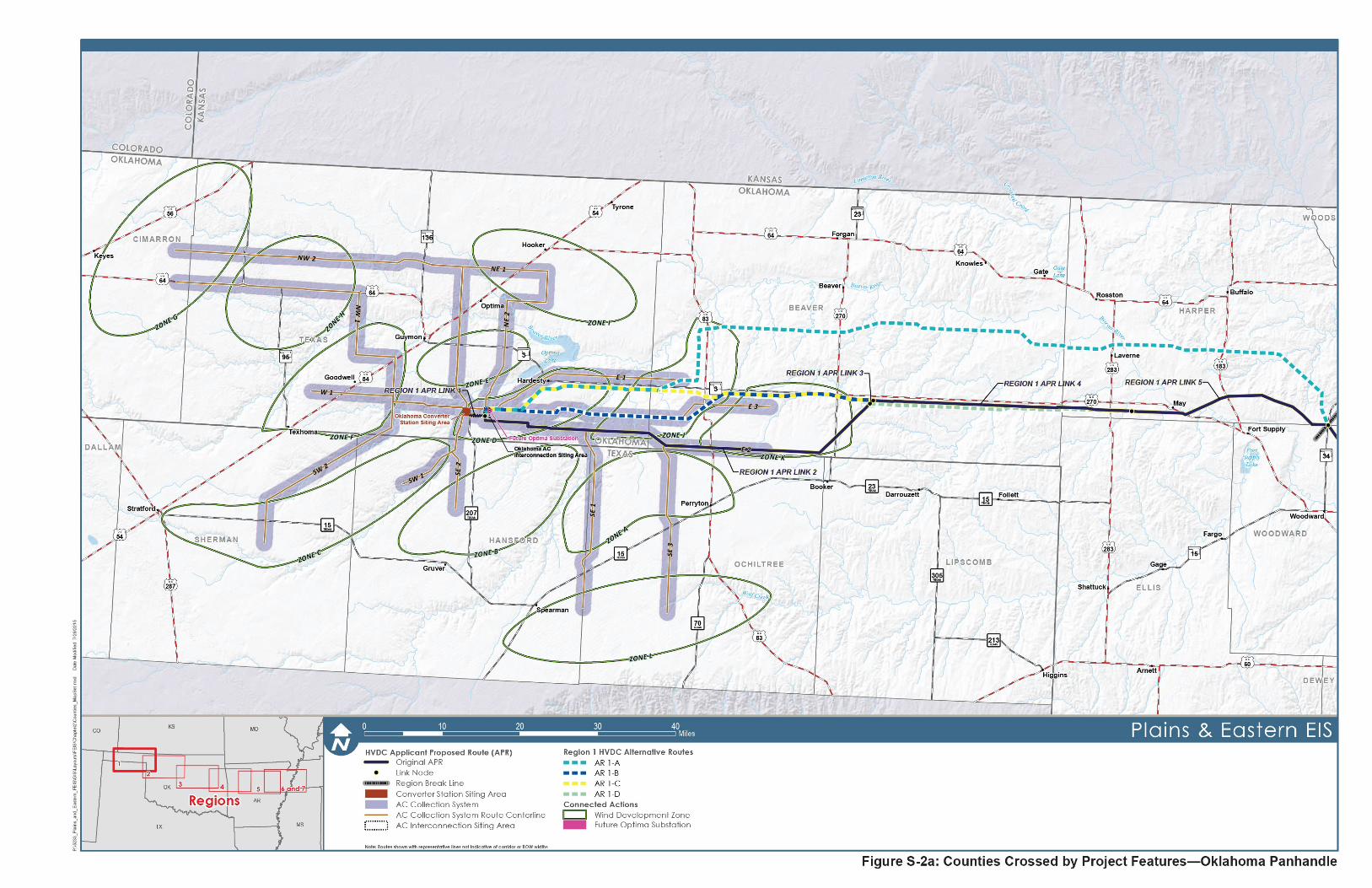
Figure S-2a: Counties Crossed by Project Features—Oklahoma Panhandle .............................................................. S-5
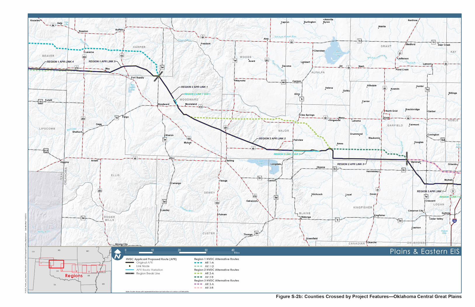
Figure S-2b: Counties Crossed by Project Features—Oklahoma Central Great Plains ............................................... S-7
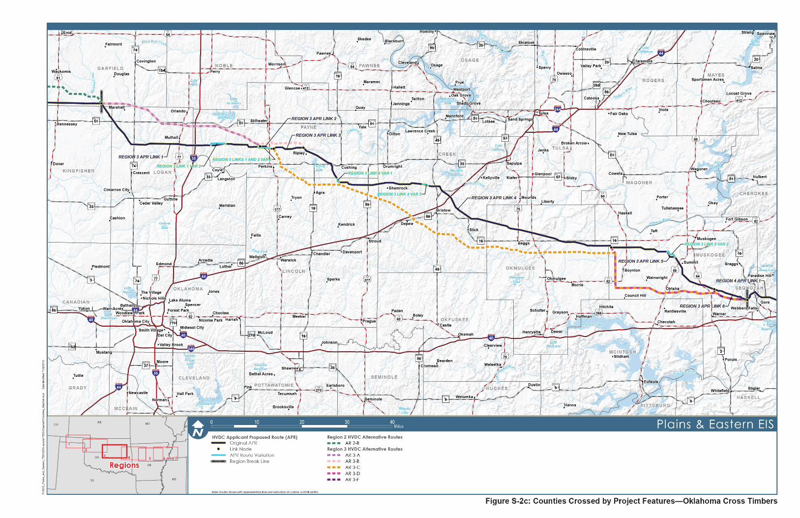
Figure S-2c: Counties Crossed by Project Features—Oklahoma Cross Timbers ........................................................ S-9
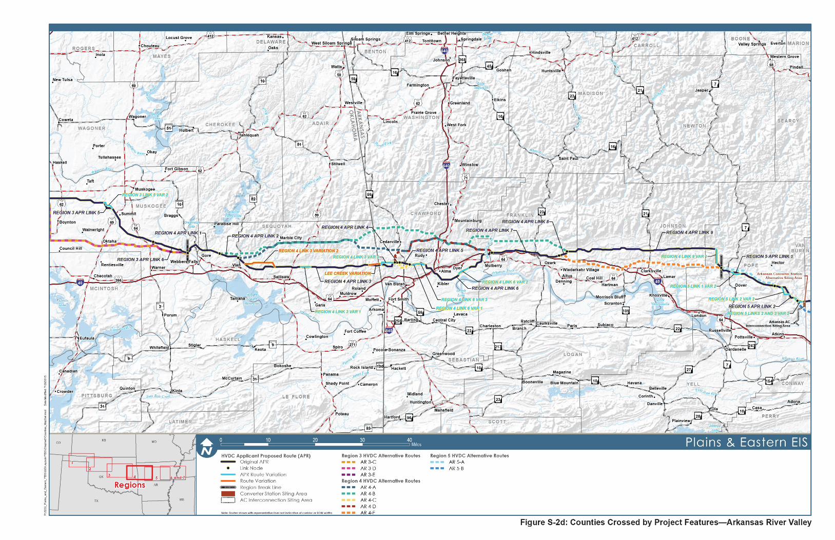
Figure S-2d: Counties Crossed by Project Features—Arkansas River Valley ............................................................ S-11
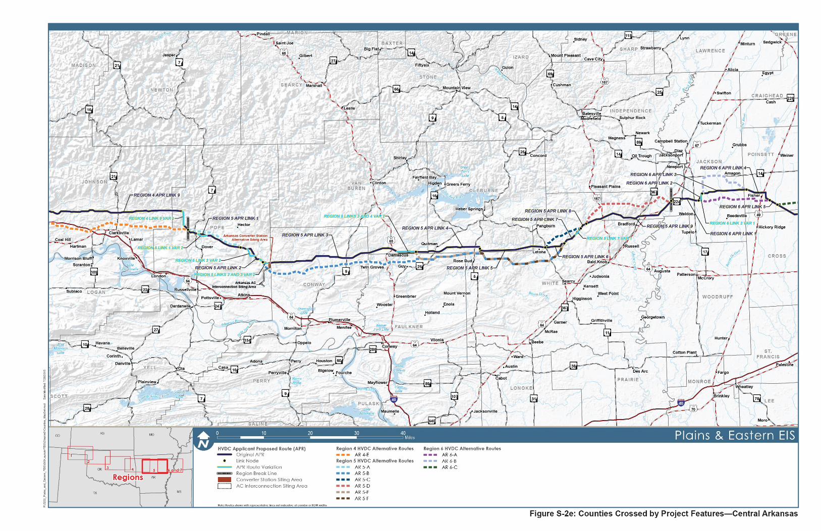
Figure S-2e: Counties Crossed by Project Features—Central Arkansas ................................................................... S-13
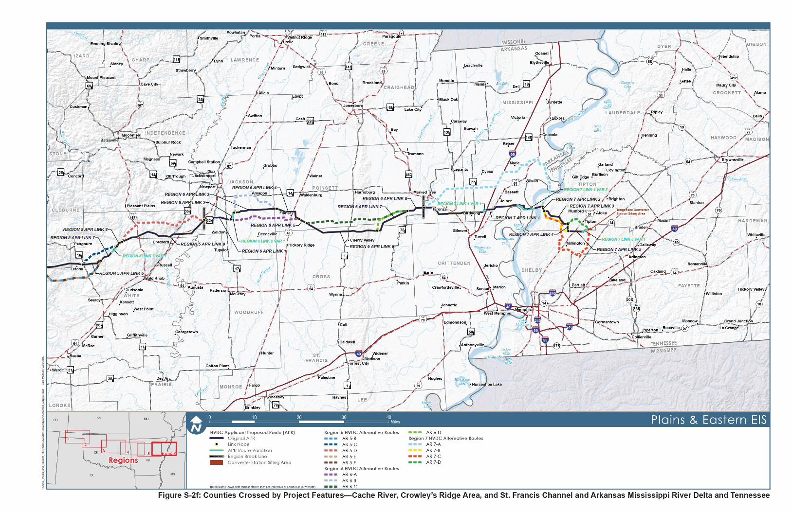
Figure S-2f: Counties Crossed by Project Features—Cache River, Crowley’s Ridge Area, and St. Francis Channel and Arkansas Mississippi River Delta and Tennessee ............................................................ S-15
Figure S-3: 600kV Lattice Deadend and Running Angle .......................................................................................... S-25
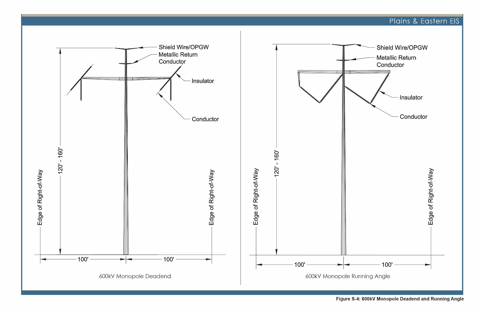
Figure S-4: 600kV Monopole Deadend and Running Angle ..................................................................................... S-27
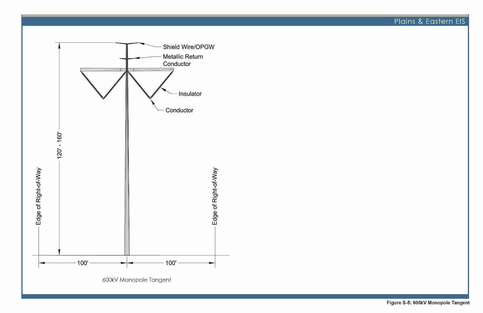
Figure S-5: 600kV Monopole Tangent ...................................................................................................................... S-29
Figure S-6: AC Collection System Routes ................................................................................................................ S-31
Figure S-7: HVDC Transmission Line Construction Sequence................................................................................. S-35

SUMMARY
PLAINS & EASTERN S-vi FINAL ENVIRONMENTAL IMPACT STATEMENT
This page intentionally left blank.
SUMMARY
PLAINS & EASTERN FINAL ENVIRONMENTAL IMPACT STATEMENT S-vii
Acronyms and Abbreviations
AC Alternating Current ACGIH American Conference of Governmental Industrial Hygienists APR Applicant Proposed Route AR Alternative Route BIA Bureau of Indian Affairs BMP Best Management Practice CEQ Council on Environmental Quality CFR Code of Federal Regulations dBA A-weighted dB scale DC Direct Current DOE U.S. Department of Energy EIS Environmental Impact Statement EPA U.S. Environmental Protection Agency EPAct Energy Policy Act of 2005 EPM Environmental Protection Measure ESA Endangered Species Act FAA Federal Aviation Administration FR Federal Register HVDC High-Voltage Direct Current IEEE Institute of Electrical and Electronic Engineers ICNIRP International Committee on Non-Ionizing Radiation Protection kV Kilovolt kV/m Kilovolt Per Meter LEPC Lesser Prairie-Chicken LOS Level of Service MISO Midcontinent Independent System Operator MW Megawatt NEPA National Environmental Policy Act NHPA National Historic Preservation Act NRCS Natural Resources Conservation Service NRHP National Register of Historic Places NSA Noise Sensitive Area PA Programmatic Agreement RFP Request for Proposal ROD Record of Decision ROI Region of Influence ROW Right-of-Way SHPO State Historic Preservation Office Southwestern Southwestern Power Administration SPP Southwest Power Pool
SUMMARY
PLAINS & EASTERN S-viii FINAL ENVIRONMENTAL IMPACT STATEMENT
SPS Southwestern Public Service TVA Tennessee Valley Authority USACE U.S. Army Corps of Engineers USC United States Code USFWS United States Fish and Wildlife Service WDZ Wind Development Zones WMA Wildlife Management Area
SUMMARY
PLAINS & EASTERN FINAL ENVIRONMENTAL IMPACT STATEMENT S-1
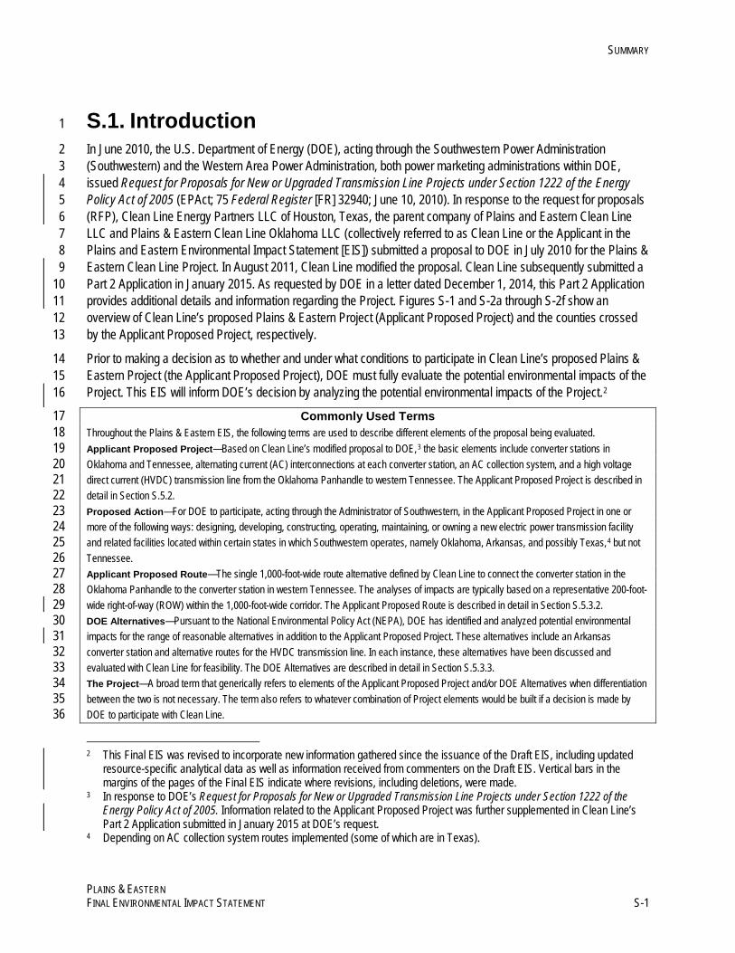
S.1. Introduction 1
In June 2010, the U.S. Department of Energy (DOE), acting through the Southwestern Power Administration 2 (Southwestern) and the Western Area Power Administration, both power marketing administrations within DOE, 3 issued Request for Proposals for New or Upgraded Transmission Line Projects under Section 1222 of the Energy 4 Policy Act of 2005 (EPAct; 75 Federal Register [FR] 32940; June 10, 2010). In response to the request for proposals 5 (RFP), Clean Line Energy Partners LLC of Houston, Texas, the parent company of Plains and Eastern Clean Line 6 LLC and Plains & Eastern Clean Line Oklahoma LLC (collectively referred to as Clean Line or the Applicant in the 7 Plains and Eastern Environmental Impact Statement [EIS]) submitted a proposal to DOE in July 2010 for the Plains & 8 Eastern Clean Line Project. In August 2011, Clean Line modified the proposal. Clean Line subsequently submitted a 9 Part 2 Application in January 2015. As requested by DOE in a letter dated December 1, 2014, this Part 2 Application 10 provides additional details and information regarding the Project. Figures S-1 and S-2a through S-2f show an 11 overview of Clean Line’s proposed Plains & Eastern Project (Applicant Proposed Project) and the counties crossed 12 by the Applicant Proposed Project, respectively. 13
Prior to making a decision as to whether and under what conditions to participate in Clean Line’s proposed Plains & 14 Eastern Project (the Applicant Proposed Project), DOE must fully evaluate the potential environmental impacts of the 15 Project. This EIS will inform DOE’s decision by analyzing the potential environmental impacts of the Project.2 16
Commonly Used Terms 17 Throughout the Plains & Eastern EIS, the following terms are used to describe different elements of the proposal being evaluated. 18 Applicant Proposed Project—Based on Clean Line’s modified proposal to DOE,3 the basic elements include converter stations in 19 Oklahoma and Tennessee, alternating current (AC) interconnections at each converter station, an AC collection system, and a high voltage 20 direct current (HVDC) transmission line from the Oklahoma Panhandle to western Tennessee. The Applicant Proposed Project is described in 21 detail in Section S.5.2. 22 Proposed Action—For DOE to participate, acting through the Administrator of Southwestern, in the Applicant Proposed Project in one or 23 more of the following ways: designing, developing, constructing, operating, maintaining, or owning a new electric power transmission facility 24 and related facilities located within certain states in which Southwestern operates, namely Oklahoma, Arkansas, and possibly Texas,4 but not 25 Tennessee. 26 Applicant Proposed Route—The single 1,000-foot-wide route alternative defined by Clean Line to connect the converter station in the 27 Oklahoma Panhandle to the converter station in western Tennessee. The analyses of impacts are typically based on a representative 200-foot-28 wide right-of-way (ROW) within the 1,000-foot-wide corridor. The Applicant Proposed Route is described in detail in Section S.5.3.2. 29 DOE Alternatives—Pursuant to the National Environmental Policy Act (NEPA), DOE has identified and analyzed potential environmental 30 impacts for the range of reasonable alternatives in addition to the Applicant Proposed Project. These alternatives include an Arkansas 31 converter station and alternative routes for the HVDC transmission line. In each instance, these alternatives have been discussed and 32 evaluated with Clean Line for feasibility. The DOE Alternatives are described in detail in Section S.5.3.3. 33 The Project—A broad term that generically refers to elements of the Applicant Proposed Project and/or DOE Alternatives when differentiation 34 between the two is not necessary. The term also refers to whatever combination of Project elements would be built if a decision is made by 35 DOE to participate with Clean Line. 36
2 This Final EIS was revised to incorporate new information gathered since the issuance of the Draft EIS, including updated
resource-specific analytical data as well as information received from commenters on the Draft EIS. Vertical bars in the margins of the pages of the Final EIS indicate where revisions, including deletions, were made.
3 In response to DOE’s Request for Proposals for New or Upgraded Transmission Line Projects under Section 1222 of the Energy Policy Act of 2005. Information related to the Applicant Proposed Project was further supplemented in Clean Line’s Part 2 Application submitted in January 2015 at DOE’s request.
4 Depending on AC collection system routes implemented (some of which are in Texas).
SUMMARY
PLAINS & EASTERN S-2 FINAL ENVIRONMENTAL IMPACT STATEMENT
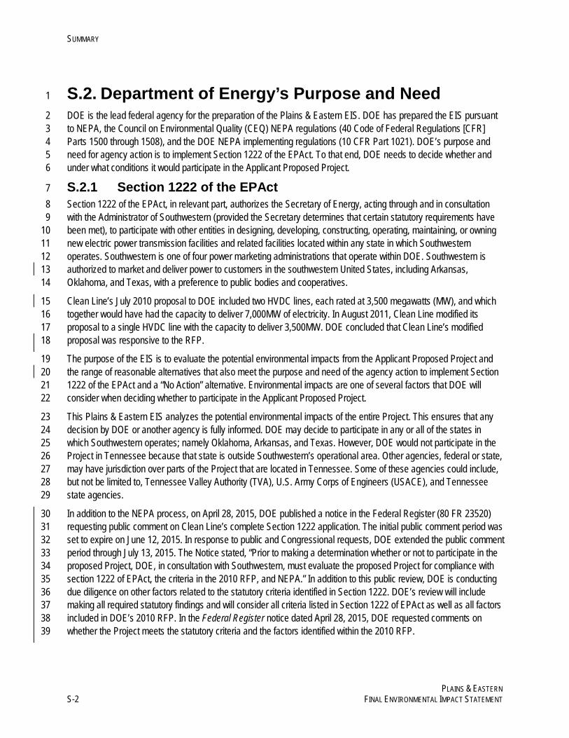
S.2. Department of Energy’s Purpose and Need 1
DOE is the lead federal agency for the preparation of the Plains & Eastern EIS. DOE has prepared the EIS pursuant 2 to NEPA, the Council on Environmental Quality (CEQ) NEPA regulations (40 Code of Federal Regulations [CFR] 3 Parts 1500 through 1508), and the DOE NEPA implementing regulations (10 CFR Part 1021). DOE’s purpose and 4 need for agency action is to implement Section 1222 of the EPAct. To that end, DOE needs to decide whether and 5 under what conditions it would participate in the Applicant Proposed Project. 6
S.2.1 Section 1222 of the EPAct 7 Section 1222 of the EPAct, in relevant part, authorizes the Secretary of Energy, acting through and in consultation 8 with the Administrator of Southwestern (provided the Secretary determines that certain statutory requirements have 9 been met), to participate with other entities in designing, developing, constructing, operating, maintaining, or owning 10 new electric power transmission facilities and related facilities located within any state in which Southwestern 11 operates. Southwestern is one of four power marketing administrations that operate within DOE. Southwestern is 12 authorized to market and deliver power to customers in the southwestern United States, including Arkansas, 13 Oklahoma, and Texas, with a preference to public bodies and cooperatives. 14
Clean Line’s July 2010 proposal to DOE included two HVDC lines, each rated at 3,500 megawatts (MW), and which 15 together would have had the capacity to deliver 7,000MW of electricity. In August 2011, Clean Line modified its 16 proposal to a single HVDC line with the capacity to deliver 3,500MW. DOE concluded that Clean Line’s modified 17 proposal was responsive to the RFP. 18
The purpose of the EIS is to evaluate the potential environmental impacts from the Applicant Proposed Project and 19 the range of reasonable alternatives that also meet the purpose and need of the agency action to implement Section 20 1222 of the EPAct and a “No Action” alternative. Environmental impacts are one of several factors that DOE will 21 consider when deciding whether to participate in the Applicant Proposed Project. 22
This Plains & Eastern EIS analyzes the potential environmental impacts of the entire Project. This ensures that any 23 decision by DOE or another agency is fully informed. DOE may decide to participate in any or all of the states in 24 which Southwestern operates; namely Oklahoma, Arkansas, and Texas. However, DOE would not participate in the 25 Project in Tennessee because that state is outside Southwestern’s operational area. Other agencies, federal or state, 26 may have jurisdiction over parts of the Project that are located in Tennessee. Some of these agencies could include, 27 but not be limited to, Tennessee Valley Authority (TVA), U.S. Army Corps of Engineers (USACE), and Tennessee 28 state agencies. 29
In addition to the NEPA process, on April 28, 2015, DOE published a notice in the Federal Register (80 FR 23520) 30 requesting public comment on Clean Line’s complete Section 1222 application. The initial public comment period was 31 set to expire on June 12, 2015. In response to public and Congressional requests, DOE extended the public comment 32 period through July 13, 2015. The Notice stated, “Prior to making a determination whether or not to participate in the 33 proposed Project, DOE, in consultation with Southwestern, must evaluate the proposed Project for compliance with 34 section 1222 of EPAct, the criteria in the 2010 RFP, and NEPA.” In addition to this public review, DOE is conducting 35 due diligence on other factors related to the statutory criteria identified in Section 1222. DOE’s review will include 36 making all required statutory findings and will consider all criteria listed in Section 1222 of EPAct as well as all factors 37 included in DOE’s 2010 RFP. In the Federal Register notice dated April 28, 2015, DOE requested comments on 38 whether the Project meets the statutory criteria and the factors identified within the 2010 RFP. 39

This page intentionally left blank.
SUMMARY
PLAINS & EASTERN FINAL ENVIRONMENTAL IMPACT STATEMENT S-17
S.3. Clean Line’s Goals and Objectives 1
In response to the DOE Request for Proposals for New or Upgraded Transmission Line Projects under Section 1222 2 of the Energy Policy Act of 2005, Clean Line prepared a proposal (submitted in July 2010, updated in August 2011, 3 and supplemented in January 2015) to develop new transmission facilities to be located in Oklahoma, Arkansas, 4 Tennessee, and possibly Texas. According to Clean Line’s initial proposal, “The Plains and Eastern Clean Line is 5 necessary to accommodate the actual and projected increase in demand for additional electric transmission capacity 6 to deliver renewable energy from western SPP [Southwest Power Pool] to load centers in the southeastern United 7 States.” Further, Clean Line’s stated objectives for development of the Applicant Proposed Project include: 8
• Improving public access to renewable energy at a competitive cost by facilitating the transfer of available wind 9 energy in the Oklahoma and Texas Panhandle regions to areas with increasing demands 10
• Providing an efficient and reliable interconnection between the SPP and TVA that facilitates the delivery of 11 3,500MW of wind-generated electricity and is consistent with applicable transmission system plans 12
• Assisting in satisfying the growing customer demand for renewable energy 13 • Providing safe, efficient and reliable transmission infrastructure consistent with prudent utility practice 14
S.4. Interagency Coordination and Public Participation 15
S.4.1 Interagency Coordination 16 DOE is the lead agency for the preparation of the Plains & Eastern EIS. As lead agency, DOE retains overall 17 responsibility for the NEPA process including the Draft and Final EIS and DOE’s Record of Decision (ROD), if any. 18 DOE’s responsibilities include determining the purpose and need for DOE’s agency action, identifying for analysis the 19 range of reasonable alternatives to its Proposed Action, identifying potential environmental impacts of the Proposed 20 Action and reasonable alternatives, identifying its preferred alternative, and determining appropriate mitigation 21 measures. 22
DOE is also the lead agency for consultation required under Section 106 of the National Historic Preservation Act 23 (NHPA), 54 United States Code (USC) § 300101 et seq. DOE is using the NEPA process and documentation 24 required for the Plains & Eastern EIS to comply with Section 106 of the NHPA in lieu of the procedures set forth in 25 Sections 800.3 through 800.6 of the NHPA. This approach is consistent with the recommendations set forth in the 26 NHPA implementing regulations that Section 106 compliance should be coordinated with actions taken to meet 27 NEPA requirements (36 CFR 800.8(a)(1)). Additional information regarding compliance with Section 106 of the 28 NHPA is provided in Section 3.9. 29
Several other agencies are participating as cooperating agencies in preparation of the Plains & Eastern EIS as 30 described in 40 CFR 1501.6. These cooperating agencies have also participated, along with other federal and state 31 agencies, in routing and siting activities related to their jurisdiction, authority, or expertise. Also, DOE has invited 32 certain federal, state, Indian Tribes or Nations, and local agencies to consult under Section 106 of the NHPA in 33 accordance with 36 CFR 800.2(c) 34
The following sections provide information regarding each cooperating agency and its responsibilities, and the basis 35 for participation as a cooperating agency. 36
SUMMARY
PLAINS & EASTERN S-18 FINAL ENVIRONMENTAL IMPACT STATEMENT
S.4.1.1 Bureau of Indian Affairs 1 The Bureau of Indian Affairs (BIA) is a bureau within the Department of the Interior responsible for the administration 2 and management of land held in trust for American Indians and federally recognized Tribes. The BIA has jurisdiction 3 by law on 25 CFR Part 169, Rights-of-Way over Indian Lands. 4
S.4.1.2 Natural Resources Conservation Service 5 The Natural Resources Conservation Service (NRCS) is a federal agency within the Department of Agriculture whose 6 mission is to provide national leadership in the conservation of soil, water, and related natural resources. The NRCS 7 provides balanced technical assistance and cooperative conservation programs to landowners and land managers 8 throughout the United States. NRCS has jurisdiction by law and/or has special expertise in the following areas: 9
• Farmland Protection Policy Act (7 USC § 4201 et seq.; 7 CFR Part 658) 10 • Watershed Protection and Flood Prevention Act (16 USC §§ 1001–1009; Public Law 83-566) 11 • Agricultural Conservation Easement Program (Subtitle D of the Agricultural Act of 2014; 128 Stat. 649, Public 12
Law 113–79) 13 • Healthy Forests Restoration Act of 2003 (16 USC § 6501 et seq., Public Law 108–148) 14 • Federal Agriculture Improvement and Reform Act of 1996 (110 Stat. 888–1197, Public Law 104127) 15
S.4.1.3 Tennessee Valley Authority 16 TVA is a federally owned corporation that provides electricity to about 9 million people in parts of seven southeastern 17 states. TVA has jurisdiction by law by virtue of the approvals that would need to be obtained from TVA before 18 interconnecting the Project to the transmission system TVA operates in the Tennessee Valley region. 19
TVA’s purpose and need for agency action is to respond to Clean Line’s request to interconnect the Project to the 20 TVA transmission system. In response to the interconnection request, TVA conducted studies that indicate certain 21 upgrades are needed to the TVA transmission system to maintain system reliability. Upgrades to TVA’s transmission 22 system would be necessary to interconnect with the Project while maintaining reliable service to its customers. 23 Additionally, TVA would need to construct a new 500kV transmission line to enable the injection of 3,500MW of 24 power from the Project. TVA would conduct its own NEPA review, tiering from this EIS, to assess the impact of the 25 upgrades and the new 500kV line. 26
S.4.1.4 U.S. Army Corps of Engineers 27 The USACE is a federal agency within the Department of Defense and has jurisdiction by law and/or has special 28 expertise in the following areas: 29
• Section 404 of the Clean Water Act (33 USC § 1344) 30 • Section 10 of the Rivers and Harbors Appropriation Act of 1899 (33 USC § 403) 31 • Modification to existing USACE projects (33 USC § 408) 32
Authorization from the USACE is required for project features that cross over, through, or under navigable waters as 33 defined under Section 10 of the Rivers and Harbors Appropriation Act of 1899. Authorization from the USACE is also 34 required for any activity that would result in discharges of dredged or fill material into waters of the United States as 35
SUMMARY
PLAINS & EASTERN FINAL ENVIRONMENTAL IMPACT STATEMENT S-19
defined in Section 404 of the Clean Water Act. If granted, the USACE authorization would be issued in the form of a 1 permit verification. 2
In addition to responsibilities identified above, 33 USC § 408 provides the authority to USACE to evaluate and 3 approve proposed modifications and activities on and near existing federally constructed projects, which includes 4 levees, navigation channels, flood channels, and harbors. Additionally, work performed within 1,500 feet of the 5 Mississippi River levees has the potential to adversely affect the ability of the levee to perform as intended. Any 6 excavation or subgrade construction within 1,500 feet of a levee would require coordination with the USACE to 7 ensure no negative impact to the level of flood risk reduction provided by the levee. 8
Permits and permit verifications from the USACE would be necessary for portions of the Applicant Proposed Project, 9 (including areas within the state of Tennessee). As a cooperating agency, the USACE will review the route 10 alternatives contained in the Plains & Eastern EIS. The USACE may consider the routing alternatives in Tennessee 11 as presented in the EIS when making its permit decisions and will use the analysis contained in the EIS to inform all 12 of its permit decisions for the Project. 13
S.4.1.5 U.S. Environmental Protection Agency 14 The U.S. Environmental Protection Agency (EPA) is a federal agency that was created in 1970 for the purpose of 15 protecting human health and the environment. EPA has 10 regional offices, each of which is responsible for 16 execution of their program. Region 4 (Southeast) includes the state of Tennessee. Region 6 (South-Central) includes 17 the other states potentially involved in the Project (Arkansas, Oklahoma, and Texas). The EPA (Regions 4 and 6) has 18 jurisdiction by law and/or has special expertise in the following areas: 19
• Environmental laws 20 • Executive Orders dealing with environmental review of actions 21 • NEPA assessment and procedures 22
In addition, under Section 309 of the Clean Air Act, the EPA is required to review and publicly comment on the 23 environmental effects of major federal actions, including actions that are the subject of EIS documents. If the EPA 24 determines that the action is environmentally unsatisfactory (per the Section 309 criteria), it is required by 25 Section 309 to refer the matter to the CEQ. 26
S.4.1.6 U.S. Fish and Wildlife Service 27 The U.S. Fish and Wildlife Service (USFWS) is a bureau within the Department of the Interior whose mission is to 28 conserve, protect, and enhance fish, wildlife, and plants and their natural habitats for the continuing benefit of the 29 American people. USFWS has jurisdiction by law and/or has special expertise in the following areas: 30
• Endangered Species Act (16 USC § 1531 et seq.) 31 • Migratory Bird Treaty Act (16 USC § 703 et seq.) 32 • Bald and Golden Eagle Protection Act (16 USC § 668 et seq.) 33
SUMMARY
PLAINS & EASTERN S-20 FINAL ENVIRONMENTAL IMPACT STATEMENT
• The National Wildlife Refuge System Administration Act of 1966 (16 USC §§ 668dd–68ee) 1 • Executive Order 13186 and DOE and USFWS Memorandum of Understanding5 2
In March 2015, DOE, Southwestern, and TVA requested the initiation of formal consultation and conference with the 3 USFWS under Section 7(a)(2) of the Endangered Species Act (ESA) and submitted a Biological Assessment 4 regarding the Project and its potential effects on listed species and designated critical habitat. The Biological 5 Assessment and addendum have been included as Appendix O of this EIS. The Biological Opinion, to be issued by 6 the USFWS prior to the issuance of the ROD, may identify additional protective measures to avoid or minimize 7 impacts to special status species. 8
S.4.2 Public Participation 9 In accordance with the NEPA process, public participation formally began as part of public scoping, which started 10 with DOE’s publication of the Notice of Intent on December 21, 2012. The public scoping period continued for 11 90 days through March 21, 2013. DOE held 13 public scoping meetings in communities along the proposed and 12 alternative routes and held five interagency meetings during the scoping period. The purpose of scoping was for DOE 13 to request and receive comments on the scope of the EIS from the public, agencies, tribes, and other interested 14 parties. At the public scoping and agency meetings, DOE presented large-scale maps (42 inches by 60 inches) of the 15 potential project area to gather input on the potential transmission line routing. 16
DOE received 664 scoping comment documents, many of which included multiple scoping comments. DOE reviewed 17 all scoping comments and published a Scoping Summary Report (presented as Appendix E of the EIS). The scoping 18 comments assisted DOE in defining the scope of the analysis and alternatives included in the Plains & Eastern EIS. 19 For example, in response to scoping comments, DOE analyzed the potential impacts of an alternative with a 20 proposed converter station in Arkansas, which would facilitate the delivery of up to 500MW of electricity to the grid in 21 Arkansas. 22
The public expressed concerns regarding potential impacts to agricultural operations and equipment, impacts to 23 visual resources that include views from residences or recreation areas, the potential use of eminent domain, Project 24 routing near residential areas, potential impacts to property values, and potential health and safety issues associated 25 with electrical and magnetic fields. Other topics identified by federal agencies and Indian Tribes include potential 26 impacts to the lesser prairie-chicken and other species, crossings of large rivers, and potential impacts to cultural 27 resources. 28
EPA published a Notice of Availability in the Federal Register (79 FR 78088) announcing the comment period for the 29 Draft EIS. DOE published a separate Notice of Availability for the Draft EIS in the Federal Register (79 FR 75132), 30 which included the locations, dates, and times of the public hearings regarding the Draft EIS and identified the 31 methods for submitting comments during the 90-day public comment period. This information was also posted on the 32 Project’s EIS website (http://www.plainsandeasterneis.com). 33
5 Memorandum of Understanding Between the United States Department of Energy and the United States Fish and Wildlife
Service Regarding Implementation of Executive Order 13186, “Responsibilities of Federal Agencies to Protect Migratory Birds.” 2013. <http://energy.gov/sites/prod/files/2013/10/f3/Final%20DOE-FWS%20Migratory%20Bird%20MOU.pdf>.
SUMMARY
PLAINS & EASTERN FINAL ENVIRONMENTAL IMPACT STATEMENT S-21
The 90-day public comment period for the Draft EIS began on December 19, 2014, and was scheduled to end on 1 March 19, 2015 (79 FR 78079). On February 12, 2015, the DOE announced in the Federal Register that it was 2 extending the comment period until April 20, 2015 (80 FR 7850). DOE considered comments submitted after the 3 close of the comment period to the extent practicable. 4
During the comment period, DOE held 15 public hearings in the following locations: Woodward, Oklahoma; Guymon, 5 Oklahoma; Beaver, Oklahoma; Perryton, Texas; Muskogee, Oklahoma; Cushing, Oklahoma; Stillwater, Oklahoma; 6 Enid, Oklahoma; Newport, Arkansas; Searcy, Arkansas; Marked Tree, Arkansas; Millington, Tennessee; Russellville, 7 Arkansas; Fort Smith, Arkansas; and Morrilton, Arkansas. There were 1,400 people signed in at the 15 meetings for 8 an average sign-in attendance of 93 individuals. Approximately 270 commenters spoke at the 15 public hearings. 9
Approximately 950 comment documents were received from individuals, interested groups, tribal governments, and 10 federal, state, and local agencies during the public comment period on the Draft EIS. This total includes a single copy 11 of documents that were received as part of 50 e-mail and letter campaigns (i.e., identical letters signed and submitted 12 by more than one commenter). The total number of campaign documents was approximately 1,700 emails or letters. 13 The comment documents consisted of emails or electronic submittals, hand-ins at the public hearings, campaigns or 14 petitions, comments received through the U.S. mail, and hearing transcripts. The comments contained within these 15 comment documents have been addressed in the Comment Response Document (Appendix Q). The primary topics 16 raised include, but are not limited to, easement acquisition and property rights, routing issues, and potential health 17 effects associated with electromagnetic fields. 18
S.5. Project Description and Alternatives 19
S.5.1 DOE Proposed Action 20 DOE’s Proposed Action is to participate, acting through the Administrator of Southwestern, in the Applicant Proposed 21 Project in one or more of the following ways: designing, developing, constructing, operating, maintaining, or owning a 22 new electric power transmission facility and related facilities located within certain states in which Southwestern 23 operates: namely Oklahoma, Arkansas and possibly Texas. 24
S.5.2 Applicant Proposed Project Description 25 The Applicant Proposed Project would include an overhead ±600 kilovolt (kV) HVDC electric transmission system 26 and associated facilities with the capacity to deliver approximately 3,500MW, primarily from renewable energy 27 generation facilities in the Oklahoma and Texas Panhandle regions, to load-serving entities in the Mid-South and 28 Southeast United States via an interconnection with TVA in Tennessee. 29
Major facilities associated with the Applicant Proposed Project consist of converter stations in Oklahoma and 30 Tennessee, an approximate 720-mile, ±600kV HVDC transmission line, an AC collection system, and access roads. 31 The following sections summarize the Applicant Proposed Project’s major facilities and improvements. 32
S.5.2.1 Converter Stations and Other Terminal Facilities 33 The Applicant Proposed Project includes two AC/direct current (DC) converter stations, one at each end of the HVDC 34 transmission line. The Applicant proposes to locate a converter station in Texas County, Oklahoma, and a converter 35
SUMMARY
PLAINS & EASTERN S-22 FINAL ENVIRONMENTAL IMPACT STATEMENT
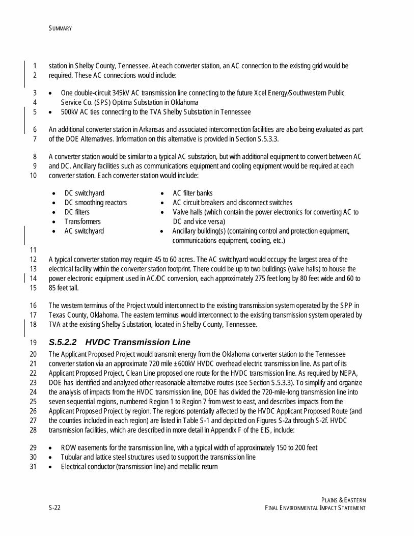
station in Shelby County, Tennessee. At each converter station, an AC connection to the existing grid would be 1 required. These AC connections would include: 2
• One double-circuit 345kV AC transmission line connecting to the future Xcel Energy/Southwestern Public 3 Service Co. (SPS) Optima Substation in Oklahoma 4
• 500kV AC ties connecting to the TVA Shelby Substation in Tennessee 5
An additional converter station in Arkansas and associated interconnection facilities are also being evaluated as part 6 of the DOE Alternatives. Information on this alternative is provided in Section S.5.3.3. 7
A converter station would be similar to a typical AC substation, but with additional equipment to convert between AC 8 and DC. Ancillary facilities such as communications equipment and cooling equipment would be required at each 9 converter station. Each converter station would include: 10
• DC switchyard • AC filter banks • DC smoothing reactors • AC circuit breakers and disconnect switches • DC filters • Transformers
• Valve halls (which contain the power electronics for converting AC to DC and vice versa)
• AC switchyard • Ancillary building(s) (containing control and protection equipment, communications equipment, cooling, etc.)
11 A typical converter station may require 45 to 60 acres. The AC switchyard would occupy the largest area of the 12 electrical facility within the converter station footprint. There could be up to two buildings (valve halls) to house the 13 power electronic equipment used in AC/DC conversion, each approximately 275 feet long by 80 feet wide and 60 to 14 85 feet tall. 15
The western terminus of the Project would interconnect to the existing transmission system operated by the SPP in 16 Texas County, Oklahoma. The eastern terminus would interconnect to the existing transmission system operated by 17 TVA at the existing Shelby Substation, located in Shelby County, Tennessee. 18
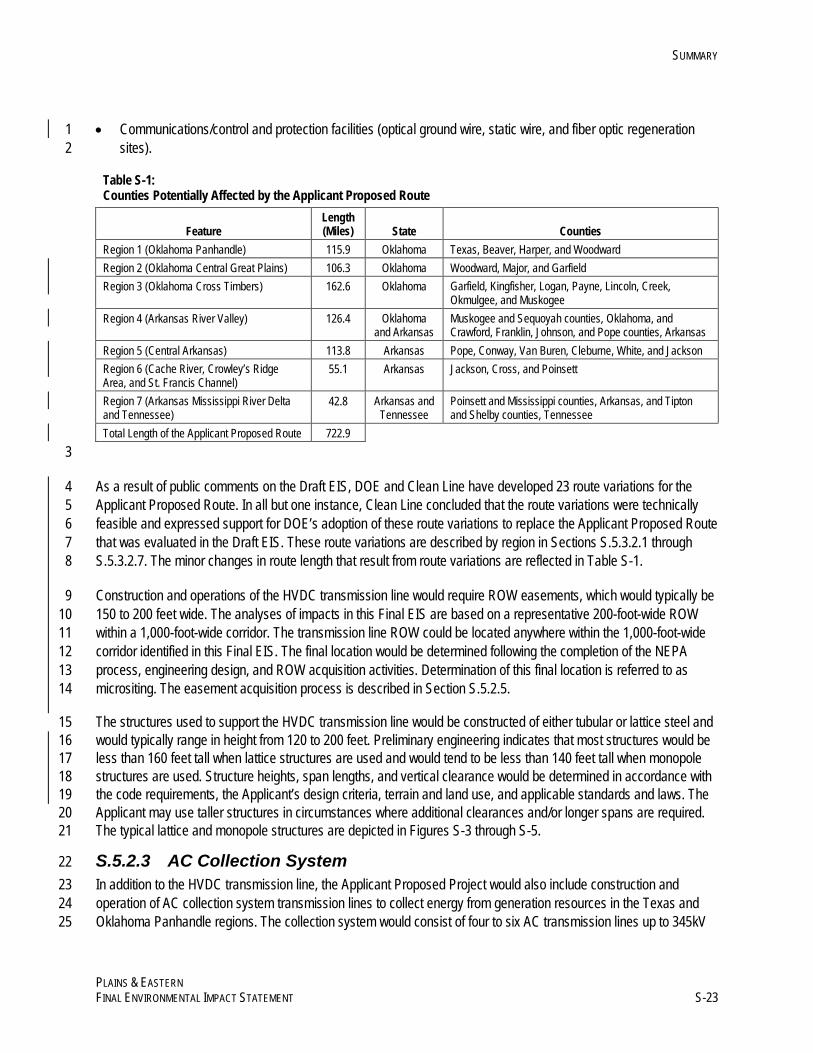
S.5.2.2 HVDC Transmission Line 19 The Applicant Proposed Project would transmit energy from the Oklahoma converter station to the Tennessee 20 converter station via an approximate 720 mile ±600kV HVDC overhead electric transmission line. As part of its 21 Applicant Proposed Project, Clean Line proposed one route for the HVDC transmission line. As required by NEPA, 22 DOE has identified and analyzed other reasonable alternative routes (see Section S.5.3.3). To simplify and organize 23 the analysis of impacts from the HVDC transmission line, DOE has divided the 720-mile-long transmission line into 24 seven sequential regions, numbered Region 1 to Region 7 from west to east, and describes impacts from the 25 Applicant Proposed Project by region. The regions potentially affected by the HVDC Applicant Proposed Route (and 26 the counties included in each region) are listed in Table S-1 and depicted on Figures S-2a through S-2f. HVDC 27 transmission facilities, which are described in more detail in Appendix F of the EIS, include: 28
• ROW easements for the transmission line, with a typical width of approximately 150 to 200 feet 29 • Tubular and lattice steel structures used to support the transmission line 30 • Electrical conductor (transmission line) and metallic return 31
SUMMARY
PLAINS & EASTERN FINAL ENVIRONMENTAL IMPACT STATEMENT S-23
• Communications/control and protection facilities (optical ground wire, static wire, and fiber optic regeneration 1 sites). 2
Table S-1: Counties Potentially Affected by the Applicant Proposed Route
Feature Length (Miles) State Counties
Region 1 (Oklahoma Panhandle) 115.9 Oklahoma Texas, Beaver, Harper, and Woodward Region 2 (Oklahoma Central Great Plains) 106.3 Oklahoma Woodward, Major, and Garfield Region 3 (Oklahoma Cross Timbers) 162.6 Oklahoma Garfield, Kingfisher, Logan, Payne, Lincoln, Creek,
Okmulgee, and Muskogee Region 4 (Arkansas River Valley) 126.4 Oklahoma
and Arkansas Muskogee and Sequoyah counties, Oklahoma, and Crawford, Franklin, Johnson, and Pope counties, Arkansas
Region 5 (Central Arkansas) 113.8 Arkansas Pope, Conway, Van Buren, Cleburne, White, and Jackson Region 6 (Cache River, Crowley’s Ridge Area, and St. Francis Channel)
55.1 Arkansas Jackson, Cross, and Poinsett
Region 7 (Arkansas Mississippi River Delta and Tennessee)
42.8 Arkansas and Tennessee
Poinsett and Mississippi counties, Arkansas, and Tipton and Shelby counties, Tennessee
Total Length of the Applicant Proposed Route 722.9 3
As a result of public comments on the Draft EIS, DOE and Clean Line have developed 23 route variations for the 4 Applicant Proposed Route. In all but one instance, Clean Line concluded that the route variations were technically 5 feasible and expressed support for DOE’s adoption of these route variations to replace the Applicant Proposed Route 6 that was evaluated in the Draft EIS. These route variations are described by region in Sections S.5.3.2.1 through 7 S.5.3.2.7. The minor changes in route length that result from route variations are reflected in Table S-1. 8
Construction and operations of the HVDC transmission line would require ROW easements, which would typically be 9 150 to 200 feet wide. The analyses of impacts in this Final EIS are based on a representative 200-foot-wide ROW 10 within a 1,000-foot-wide corridor. The transmission line ROW could be located anywhere within the 1,000-foot-wide 11 corridor identified in this Final EIS. The final location would be determined following the completion of the NEPA 12 process, engineering design, and ROW acquisition activities. Determination of this final location is referred to as 13 micrositing. The easement acquisition process is described in Section S.5.2.5. 14
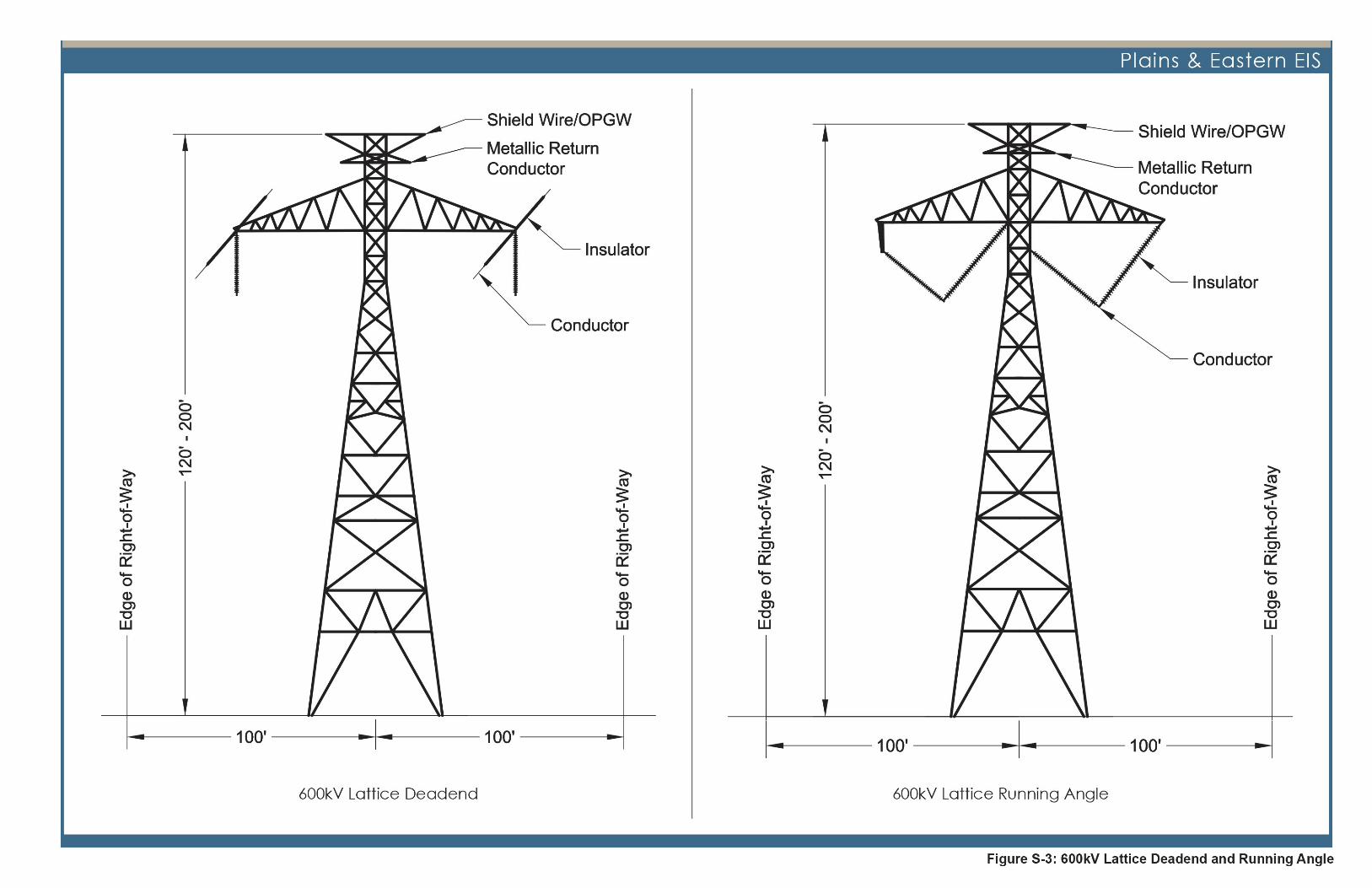
The structures used to support the HVDC transmission line would be constructed of either tubular or lattice steel and 15 would typically range in height from 120 to 200 feet. Preliminary engineering indicates that most structures would be 16 less than 160 feet tall when lattice structures are used and would tend to be less than 140 feet tall when monopole 17 structures are used. Structure heights, span lengths, and vertical clearance would be determined in accordance with 18 the code requirements, the Applicant’s design criteria, terrain and land use, and applicable standards and laws. The 19 Applicant may use taller structures in circumstances where additional clearances and/or longer spans are required. 20 The typical lattice and monopole structures are depicted in Figures S-3 through S-5. 21
S.5.2.3 AC Collection System 22 In addition to the HVDC transmission line, the Applicant Proposed Project would also include construction and 23 operation of AC collection system transmission lines to collect energy from generation resources in the Texas and 24 Oklahoma Panhandle regions. The collection system would consist of four to six AC transmission lines up to 345kV 25
SUMMARY
PLAINS & EASTERN S-24 FINAL ENVIRONMENTAL IMPACT STATEMENT
from the Oklahoma converter station to points in the Oklahoma or Texas Panhandle to facilitate efficient 1 interconnection of wind energy generation. The interconnection points with this wind energy generation would likely 2 be within a 40-mile radius from the Oklahoma Converter Station Siting Area. Components of the AC collection 3 system include: 4
• ROW easements for the transmission line, with a typical width of 150 to 200 feet 5 • Tubular or lattice steel structures used to support the transmission line 6 • Electrical conductor 7 • Communications/control and protection facilities (optical ground wire, static wire, and fiber optic regeneration sites) 8
The Applicant expects that future wind energy generation facilities (wind farms) would connect to the AC collection 9 system by way of a number of possible configurations. The Applicant based the 40-mile radius on preliminary studies 10 of engineering constraints and wind resource data, industry knowledge, and economic feasibility. These 11 configurations could range in size from a direct tap, a ring bus, or even a small substation (about 2 to 5 acres in size) 12 with transformer and switching equipment. The type and size of these AC connections is unknown at this time; the 13 final design of these facilities would depend on a number of factors including their location, the number of 14 connections, and the nameplate capacity and voltage of generation facilities. 15
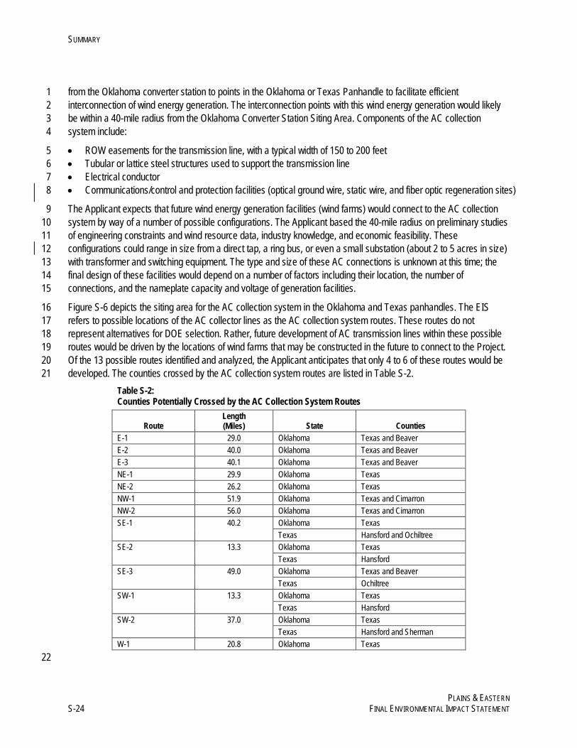
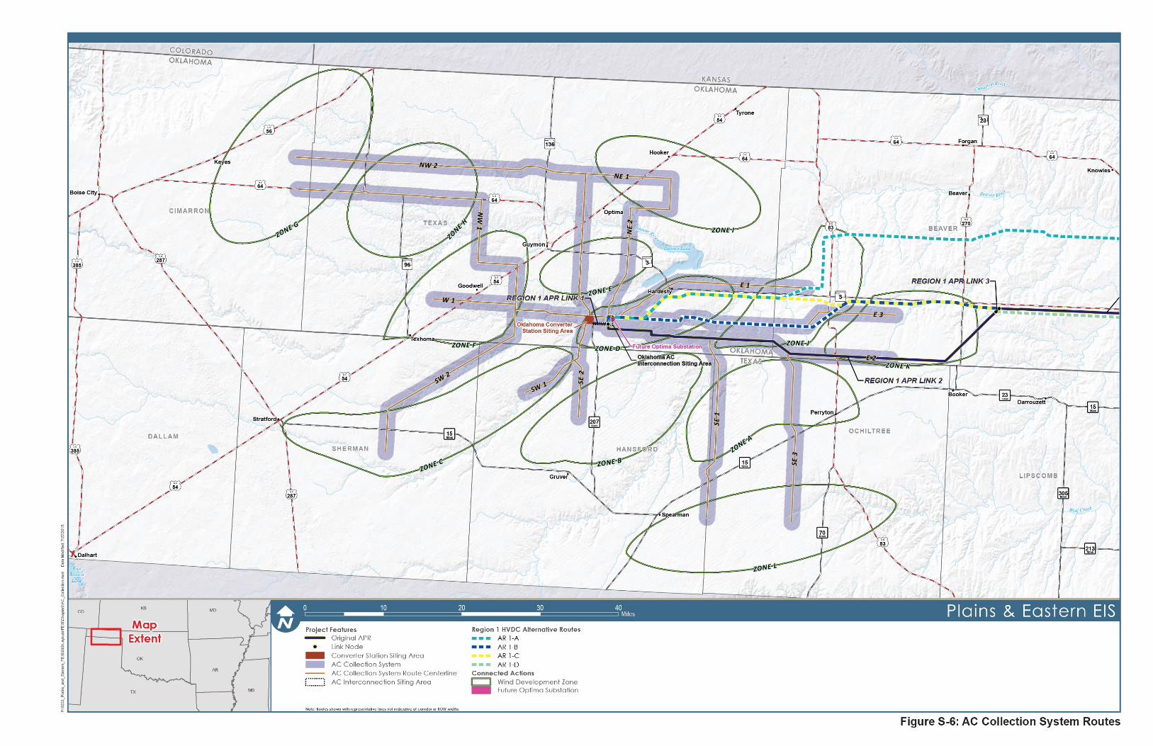
Figure S-6 depicts the siting area for the AC collection system in the Oklahoma and Texas panhandles. The EIS 16 refers to possible locations of the AC collector lines as the AC collection system routes. These routes do not 17 represent alternatives for DOE selection. Rather, future development of AC transmission lines within these possible 18 routes would be driven by the locations of wind farms that may be constructed in the future to connect to the Project. 19 Of the 13 possible routes identified and analyzed, the Applicant anticipates that only 4 to 6 of these routes would be 20 developed. The counties crossed by the AC collection system routes are listed in Table S-2. 21
Table S-2: Counties Potentially Crossed by the AC Collection System Routes
Route Length (Miles) State Counties
E-1 29.0 Oklahoma Texas and Beaver E-2 40.0 Oklahoma Texas and Beaver E-3 40.1 Oklahoma Texas and Beaver NE-1 29.9 Oklahoma Texas NE-2 26.2 Oklahoma Texas NW-1 51.9 Oklahoma Texas and Cimarron NW-2 56.0 Oklahoma Texas and Cimarron SE-1 40.2 Oklahoma Texas Texas Hansford and Ochiltree SE-2 13.3 Oklahoma Texas Texas Hansford SE-3 49.0 Oklahoma Texas and Beaver Texas Ochiltree SW-1 13.3 Oklahoma Texas Texas Hansford SW-2 37.0 Oklahoma Texas Texas Hansford and Sherman W-1 20.8 Oklahoma Texas
22
SUMMARY
PLAINS & EASTERN FINAL ENVIRONMENTAL IMPACT STATEMENT S-33
S.5.2.4 Access Roads 1 Access roads would be necessary for the Project during both construction and operation. The Applicant intends to 2 maximize the use of existing public and private roads to the extent practicable, improve existing private roads where 3 they are insufficient, and build new roads where existing roads are not available. During construction, use of existing 4 and new roads would be required to access transmission ROWs, structure locations, fiber optic regeneration sites, 5 and temporary construction areas during construction. During operations and maintenance, roads would be used for 6 access to transmission ROWs (for vegetation management and movement of maintenance equipment), structure 7 locations, and fiber optic regeneration sites. The Applicant does not anticipate the need for a new permanent access 8 road along the entire length of transmission line ROWs and would locate access roads between structures in active 9 agricultural areas along fence lines or field lines where practicable to minimize impacts. The Applicant has no plans 10 for improvements to public roads (e.g., highways, state roads, or county roads). The Applicant plans to repair existing 11 private roads before and after construction. Paving of roads would be limited to approach aprons at intersections with 12 existing paved roads and all-weather access roads to converter stations, unless otherwise required by jurisdictional 13 authorities. 14
Site conditions, engineering design, construction requirements, environmental protection measures (EPMs) and 15 relevant permits would govern the specific locations of proposed new and existing access roads. 16
S.5.2.5 Easements and Property Rights 17 Prior to construction, the Applicant or DOE, if it elects to participate in the Project, would acquire property interests 18 from owners of land along the path of the Project. These interests could take the form of a temporary easement to 19 allow for access roads and storage yards that will be needed during construction. They could also take the form of 20 longer term easements or fee estates (i.e., full ownership) for siting transmission line towers, converter stations, and 21 other facilities. The acquisition of these property interests would not in themselves result in any environmental 22 impacts. Any potential environmental impacts to these property interests would be associated with the land use and 23 activities that would occur within the ROW; these impacts are evaluated in this EIS. 24
Any property interests in land needed for the Project would be acquired through a negotiated sale or eminent domain 25 proceedings, land owners would be compensated for their property interests. According to the Applicant’s expressed 26 intent, the first step would be for the Applicant to offer compensation to landowners in exchange for easements or 27 other property interests needed for the Project. If the Applicant is unable to acquire the necessary property interests 28 from a landowner through a negotiated agreement, DOE may choose to acquire those property interests through a 29 negotiated agreement for compensation. Where a negotiated agreement is not possible, DOE, acting through 30 Southwestern, may in appropriate circumstances exercise the federal government’s eminent domain authority to 31 acquire the interests. Consistent with the Constitution of the United States and other applicable law, the landowner 32 would be paid just compensation for the real estate interest. Real estate acquisition by federal entities, such as DOE, 33 is governed by the Uniform Relocation Assistance and Real Property Acquisition Policies Act of 1970 (42 USC 34 § 4601 et seq., Public Law 91-646). DOE must also comply with 49 CFR Part 24, Subpart B, “Real Property 35 Acquisition,” the government-wide regulation that implements Public Law 91-646. 36
S.5.2.6 Project Construction 37 Construction activities would be subject to measures/requirements imposed as part of federal, state, or local permits 38 and authorizations. The construction of a typical converter station would include: 39
SUMMARY
PLAINS & EASTERN S-34 FINAL ENVIRONMENTAL IMPACT STATEMENT
• Land surveying and staking 1 • Pre-construction surveys for biological and cultural resources 2 • Clearing and grubbing, grading, and construction of all-weather access roads 3 • Fencing 4 • Compaction and foundation installation 5 • Installation of underground electrical raceways and grounds 6 • Steel-structure erection and area lighting 7 • Installation of insulators, bus bar, and high-voltage equipment 8 • Installation of control and protection equipment 9 • Placement of final crushed-rock surface 10 • Installation of security systems, including cameras 11 • Testing and electrical energization 12
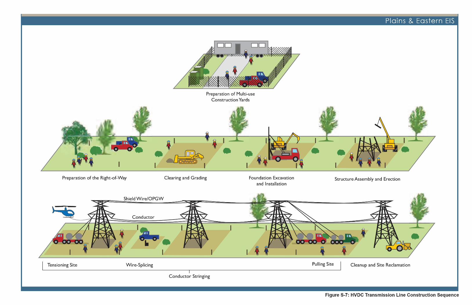
Construction activities for the HVDC and AC transmission lines would typically include the following activities: 13
• Preparation of multi-use construction yards 14 • Pre-construction surveys for biological and cultural resources 15 • Preparation of the ROW 16 • Clearing and grading 17 • Foundation excavation and installation 18 • Structure assembly and erection 19 • Conductor stringing 20 • Grounding 21 • Cleanup and site restoration 22
Figure S-7 illustrates these activities and the typical transmission construction sequence. 23
The duration of construction is expected to be approximately 36 to 42 months for the entire Project, including the time 24 from initiation of clearing and grading through clean up and restoration. The actual construction duration would 25 depend on a number of factors such as weather and availability of labor. The Applicant would most likely divide the 26 Project into five segments with multiple contractors working concurrently on different portions of the route. 27 Construction may be active on any or all segments at any given time and activities may occur in parallel with other 28 segments or be staggered. The Applicant would stage construction on each segment (and on the AC collection 29 system) from multi-use construction yards located at regular intervals (approximately every 25 miles) along the route. 30
Project-wide, the workforce would reach a peak of approximately 2,431 workers. The average workforce across the 31 Applicant Proposed Project would be approximately 1,260 people. 32
Temporary construction areas would be required to support construction. Temporary multi-use construction yards 33 and fly yards (landing areas for helicopters used during construction) would be used for staging construction 34 personnel and equipment, and for storage of materials to support construction activities. Tensioning or pulling sites 35 and wire-splicing sites would also be staged at 2- to 3-mile intervals along the Project ROW. Typically, temporary 36 construction areas would be sited outside the ROW at regular intervals and at convenient distances from the facilities 37 being constructed for the Project. 38

This page intentionally left blank.
SUMMARY
PLAINS & EASTERN FINAL ENVIRONMENTAL IMPACT STATEMENT S-37
S.5.2.7 Operations and Maintenance 1 All transmission lines would be inspected regularly or as necessary using fixed-wing aircraft, helicopters, ground 2 vehicles, all-terrain vehicles, and/or personnel on foot. The frequency of inspections and maintenance would meet or 3 exceed standards, such as those specified by the National Electrical Safety Code and North American Electric 4 Reliability Corporation. Applicable federal, state, and local permits would be obtained prior to conducting 5 maintenance. 6
The ROW would be maintained during operation in accordance with a project-specific Transmission Vegetation 7 Management Plan that would be developed by the Applicant for the Project, consistent with rules developed by the 8 North American Electric Reliability Corporation. In most areas, accepted standard utility practices consistent with the 9 Transmission Vegetation Management Plan, such as tree-trimming, tree removal, and/or brush removal, would be 10 utilized to maintain vegetation within the ROW. In addition, vegetation clearing practices may vary based on 11 dominant plant communities. 12
The Applicant expects that operations and maintenance of the Project would require 72 to 87 full-time workers. This 13 would include up to 15 workers at each of the converter stations and a total of 42 workers in Oklahoma and Arkansas 14 for the HVDC transmission line. 15
S.5.2.8 Decommissioning 16 A transmission system lifetime can exceed 80 years with proper maintenance. At the end of the service life of the 17 Project, conductors, insulators, and structures could be dismantled and removed. The converter stations and 18 regeneration stations, if not needed for other existing transmission line projects, could also be dismantled and 19 removed. The station structures would be disassembled and either used at another station or sold for scrap. Access 20 roads that have a sole purpose of providing maintenance crews access to the transmission lines could be 21 decommissioned following removal of the structures and lines, or could be decommissioned with the lines in service if 22 determined to no longer be necessary. The Applicant would consult with landowners to assess whether access roads 23 may be useful to them and the Applicant may elect to leave the access roads in place. A Decommissioning Plan 24 would be developed prior to decommissioning and would follow appropriate governing requirements at that time. 25
S.5.3 Alternatives 26 In the EIS, DOE analyzes the potential environmental impacts of the Proposed Action, the range of reasonable 27 alternatives, and a No Action Alternative. In addition, in Section S.5.3.4, DOE describes other alternatives that were 28 identified during the EIS scoping process that DOE considered but eliminated from detailed analysis. 29
S.5.3.1 No Action Alternative 30 This EIS analyzes a No Action Alternative, under which DOE would not participate with the Applicant in the Project. 31 Under the No Action Alternative, DOE assumes for analytical purposes that the Project would not proceed and none 32 of the potential environmental effects associated with the Project would occur. 33
S.5.3.2 Applicant Proposed Route 34 As indicated in Section S.5.2.2, the Applicant has identified a specific route for the HVDC transmission line from the 35 Oklahoma Panhandle Region to interconnect with TVA’s electrical system in western Tennessee. For purposes of 36 analysis, the Applicant Proposed Route is described below in terms of seven regions, which were based on 37 geographic similarities and common node points along the route (where the Applicant Proposed Route and HVDC 38
SUMMARY
PLAINS & EASTERN S-38 FINAL ENVIRONMENTAL IMPACT STATEMENT
alternative routes converge). Within each region, the Applicant Proposed Route is divided into links. These links 1 represent sections of the Applicant Proposed Route between points where alternative routes intersect with it. The 2 alternative routes (described in Section S.5.3.3.2) diverge from the Applicant Proposed Route and provide an 3 alternative to the corresponding links of the Applicant Proposed Route. The links are labeled on the figures of the 4 Applicant Proposed Route (Figures S-2a through S-2f). 5
As identified in Section S.5.2.2, in response to public comments, DOE and Clean Line have developed several route 6 variations to the Draft EIS Applicant Proposed Route. In all but one instance, Clean Line concluded that the route 7 variations were technically feasible and expressed support for DOE’s adoption of these route variations to replace the 8 Applicant Proposed Route that was evaluated in the Draft EIS. In one instance (Region 4, Applicant Proposed Route 9 Link 3, Variation 2), DOE retained the original Applicant Proposed Route, and analyzed the variation as an alternative 10 route in that area (see Section S.5.3.2.4). DOE has evaluated these route variations both individually and collectively 11 and has concluded that they do not constitute substantial changes in the Proposed Action or significant new 12 circumstances or information relevant to environmental concerns. 13
S.5.3.2.1 Region 1 (Oklahoma Panhandle) 14 Region 1 includes primarily grassland/herbaceous land cover. Region 1 begins at the converter station site in Texas 15 County, Oklahoma, and continues east through Texas, Beaver, Harper, and Woodward counties approximately 16 116 miles to the area north of Woodward, Oklahoma. The Applicant Proposed Route in Region 1 is shown on 17 Figure S-2a. 18
The AC collection system is located within Region 1 and within a 40-mile radius centered on the Oklahoma Converter 19 Station Siting Area including Cimarron, Beaver, Texas, Ochiltree, Hansford, and Sherman counties. To facilitate 20 efficient interconnection of wind generated electricity, it is expected that the Applicant would construct four to six AC 21 collection transmission lines of up to 345kV from the Oklahoma converter station to points in the Oklahoma and 22 Texas Panhandle regions. The location of the AC collection system routes will be driven by future wind energy 23 development. The AC collection system is shown on Figures S-1 and S-2a. 24
No route variations are analyzed for the Applicant Proposed Route in Region 1. 25
S.5.3.2.2 Region 2 (Oklahoma Central Great Plains) 26 Region 2 includes primarily grassland/herbaceous and cultivated crop land covers. Region 2 begins north of 27 Woodward, Oklahoma, and continues southeast through Woodward, Major, and Garfield counties, Oklahoma, for 28 approximately 106 miles to end approximately 16 miles southeast of Enid, Oklahoma. The Applicant Proposed Route 29 and route variations in Region 2 are shown in Figure S-2b. 30
Two route variations are analyzed that replace previous links of the Applicant Proposed Route in Region 2: 31
• Link 1, Variation 1, is in Woodward County, approximately 6 miles east of Woodward, Oklahoma. Clean Line 32 developed the variation in response to public comments by the affected landowner. The variation would shift the 33 Applicant Proposed Route to the northeast by about 2,500 feet and would transfer potential impacts from 34 cultivated land to existing pasture land. The variation is about 0.07 mile (370 feet) longer than, and would 35 replace approximately 2.3 miles of, the original Applicant Proposed Route. 36
SUMMARY
PLAINS & EASTERN FINAL ENVIRONMENTAL IMPACT STATEMENT S-39
• Link 2, Variation 2, is in Major County, starting approximately 3.5 miles south of Fairview, Oklahoma. Clean Line 1 developed the variation in response to comments from several landowners to avoid impacts to agricultural 2 operations and increase the distance from several homes. The variation would shift the Applicant Proposed 3 Route south by about 1,100 feet near the quarter-section line that parallels many of their parcels. The variation is 4 about 0.02 mile (100 feet) longer than, and would replace approximately 9.7 miles of, the original Applicant 5 Proposed Route. 6
S.5.3.2.3 Region 3 (Oklahoma Cross Timbers) 7 Region 3 includes primarily grassland/herbaceous, deciduous forest, and pasture/hay land covers. Region 3 begins 8 southeast of Enid, Oklahoma, and continues southeast through Garfield, Kingfisher, Logan, Payne, Lincoln, Creek, 9 Okmulgee, and Muskogee counties for approximately 162 miles and ends north of Webbers Falls, Oklahoma, at the 10 Arkansas River. The eastern portion of Region 3 from Stillwater to the region’s terminal point on the eastern end has 11 more residential development than the other portions of Region 3. The Applicant Proposed Route and route 12 variations in Region 3 are shown in Figure S-2c. 13
Five route variations are analyzed that replace previous links of the Applicant Proposed Route in Region 3: 14
• Link 1, Variation 2, is in Payne County, starting approximately 7 miles east of Mulhall, Oklahoma, and about 10 15 miles southwest of Stillwater. Clean Line developed the variation in response to comments from several 16 landowners to avoid impacts to no-till cropland and to shift the Applicant Proposed Route to cross pastureland. 17 The variation would shift the route north by about 2,400 feet to parallel the half-section line. The variation is 18 about 0.41 mile (2,200 feet) longer than, and would replace approximately 3.3 miles of, the original Applicant 19 Proposed Route. 20
• Links 1 and 2, Variation 1, is in Payne County, approximately 5 miles south of Stillwater, Oklahoma. Clean Line 21 developed the variation in response to comments from several landowners to avoid recently built homes and two 22 new residential subdivisions. The route variation would generally be about 1,900 feet south of the original 23 Applicant Proposed Route to avoid these homes. The variation is about 0.02 mile (160 feet) longer than, and 24 would replace approximately 2.8 miles of, the original Applicant Proposed Route. 25
• Link 4, Variation 1, is in Lincoln County, approximately 3 miles south-southwest of Cushing, Oklahoma. Clean 26 Line developed the variation in response to comments concerning an operating quarry. The route variation would 27 avoid the quarry to the west. The variation is about 0.08 mile (420 feet) longer than, and would replace 28 approximately 0.92 mile of, the original Applicant Proposed Route. 29
• Link 4, Variation 2, is in Creek County, approximately 6 miles north-northwest of Bristow, Oklahoma. Clean Line 30 developed the variation in response to comments concerning a new house under construction within the ROW. 31 The route variation would avoid the home. The variation is about 0.05 mile (260 feet) longer than, and would 32 replace approximately 1.23 miles of, the original Applicant Proposed Route. 33
• Link 5, Variation 2, is in Muskogee County, approximately 6 miles southwest of Muskogee, Oklahoma. Clean 34 Line developed the variation in response to comments concerning an existing house that was not identified in the 35 initial routing process. The route variation would avoid the home. The variation is about 0.08 mile (420 feet) 36 shorter than, and would replace approximately 2.5 miles of, the original Applicant Proposed Route. 37
SUMMARY
PLAINS & EASTERN S-40 FINAL ENVIRONMENTAL IMPACT STATEMENT
S.5.3.2.4 Region 4 (Arkansas River Valley) 1 Region 4 includes primarily pasture/hay and deciduous forest land covers. Region 4 begins north of Webbers Falls in 2 Muskogee County, Oklahoma, and continues east though Muskogee and Sequoyah counties in Oklahoma, and 3 Crawford, Franklin, Johnson, and Pope counties in Arkansas, for approximately 127 miles, and ends north of 4 Russellville, Arkansas. The Applicant Proposed Route and route variations in Region 4 are shown in Figure S-2d. 5
The Applicant Proposed Route includes the Lee Creek Variation, which refers to a route variation near the 6 Oklahoma-Arkansas state line. It was developed by the Applicant prior to evaluation in the Draft EIS to avoid a buffer 7 zone around the Lee Creek Reservoir. It begins in Sequoyah County, Oklahoma, at a point approximately 1.9 miles 8 west of the state line, where it proceeds east-northeast for approximately 2 miles, then east-southeast, ending in 9 Crawford County, Arkansas, approximately 1.5 miles east of the state line, where it rejoins the Applicant Proposed 10 Route. 11
Six route variations are analyzed in Region 4. DOE has not adopted Link 3, Variation 2, to replace the corresponding 12 link of the Applicant Proposed Route but has analyzed this variation as an alternative route in that area. The other 13 variations would replace the corresponding links of the Applicant Proposed Route. 14
• Link 3, Variation 1, is in Sequoyah County, approximately 3.5 miles northeast of Sallisaw, Oklahoma. Clean Line 15 developed the variation in response to a landowner comment regarding impacts to their home. The variation 16 would shift the Applicant Proposed Route north to parallel the property line, avoid the home, and avoid a newly 17 identified cemetery. The variation is essentially the same length as, and would replace, the original Applicant 18 Proposed Route. 19
• Link 3, Variation 2, is in Sequoyah County, starting approximately 1 mile northeast of Vian, Oklahoma, and 20 ending approximately 3.3 miles northwest of Sallisaw. The variation was proposed in response to landowner 21 comments regarding potential impacts to their commercial operations, ranching, Deer Management Assistance 22 Program area, airstrips, and residence. The variation would shift the route north approximately 0.8 to 1.4 miles. 23 The variation is essentially the same length as the corresponding link of the Applicant Proposed Route. This 24 route variation differs from others that have been presented in the Final EIS in that it does not replace the 25 Applicant Proposed Route; the variation referred to as Applicant Proposed Route Link 3, Variation 2, is being 26 considered as a variation (potential alternative) to the Applicant Proposed Route (similarly to the Lee Creek 27 Variation; also in Region 4, Link 3). 28
• Link 3, Variation 3, is in Crawford County, Arkansas, approximately 6 miles northwest of Van Buren, Arkansas, 29 near the eastern end of the Lee Creek Variation. Clean Line developed the variation in response to landowner 30 comments that provided confirmed information about a January 2015 discovery of federally protected 31 (endangered) Ozark big-eared bats in two winter cave hibernacula near the Lee Creek Reservoir within the ROI 32 for the Applicant Proposed Route. The variation would shift the Applicant Proposed Route north by 33 approximately 0.75 mile and would resolve engineering constraints associated with complex terrain and 34 proximity to recreational trails, Teardrop Falls, and locations of existing residences as well as reduce the amount 35 of forested land and Ozark big-eared bat occurrence area crossed. The variation is about 0.25 mile (1,320 feet) 36 shorter than, and would replace approximately 3.5 miles of, the original Applicant Proposed Route. 37
• Link 6, Variation 1, is in Crawford County and approximately 3 miles north of Van Buren, Arkansas. Clean Line 38 developed the variation in response to landowner comments regarding a new home planned for construction as 39 well as two newly constructed homes located directly adjacent to the Applicant Proposed Route. The variation 40
SUMMARY
PLAINS & EASTERN FINAL ENVIRONMENTAL IMPACT STATEMENT S-41
would shift the Applicant Proposed Route to the south approximately 500 feet, parallel parcel boundaries, and 1 avoid the proposed site for this home and increase the distance from the two newly constructed homes in the 2 area. The variation is about 0.03 mile (160 feet) longer than, and would replace approximately 1.05 miles of, the 3 original Applicant Proposed Route. 4
• Link 6, Variation 2, is in Crawford County and approximately 4 miles east of Alma, Arkansas, and 3.5 miles west 5 of Mulberry, Arkansas. Clean Line developed the variation in response to landowner comments that the 6 Applicant Proposed Route would cross the northwestern corner of a parcel subject to a NRCS Wetlands 7 Reserve Program easement. The variation would shift the Applicant Proposed Route to the northwest 8 approximately 500 feet to avoid crossing the parcel subject to the Wetlands Reserve Program easement. The 9 variation is about 0.03 mile (160 feet) longer than, and would replace approximately 2.43 miles of, the original 10 Applicant Proposed Route. 11
• Route Link 6, Variation 3, is in Crawford County and approximately 3 miles north of Van Buren, Arkansas, 12 immediately east of Applicant Proposed Route Link 6, Variation 1. Clean Line developed the variation in 13 response to landowner comments expressing concern about the proximity of the Applicant Proposed Route to a 14 residence and complex terrain. The variation would adjust the route by about 500 feet from the original Applicant 15 Proposed Route to avoid residences and the difficult terrain. The variation is about 0.1 mile (530 feet) shorter 16 than, and would replace approximately 1.9 miles of, the original Applicant Proposed Route. 17
• Link 9, Variation 1, is in Pope County and approximately 8 miles east of Hagarville, Arkansas, where two bridges 18 on Arkansas Highway 164 span Big Piney Creek. Clean Line developed the variation in response to landowner 19 comments expressing concern about the proximity of the Applicant Proposed Route to a residence, a 20 campground, and complex terrain. The variation would shift the Applicant Proposed Route from the western side 21 to the eastern side of the existing Southwestern 161kV transmission line. This variation would avoid the home 22 identified by the landowner, move the line away from the campground, and eliminate potential engineering 23 challenges associated with both Arkansas Highway 164 bridges. The variation would maintain a parallel 24 alignment to the existing Southwestern 161kV transmission line. The variation is the same length as, and would 25 replace approximately 3.12 miles of, the original Applicant Proposed Route. 26
S.5.3.2.5 Region 5 (Central Arkansas) 27 Region 5 includes primarily pasture/hay, deciduous forest, and evergreen forest land covers. Region 5 begins north 28 of Russellville, in Pope County, Arkansas, and continues east through Pope, Conway, Van Buren, Faulkner, 29 Cleburne, White, and Jackson counties in Arkansas and ends southwest of Newport, in Jackson County, Arkansas, 30 for 113 miles. The Applicant Proposed Route and route variations in Region 5 are shown in Figure S-2e. 31
Five route variations are analyzed that replace previous links of the Applicant Proposed Route in Region 5: 32
• Link 1, Variation 2, is in Pope County and approximately 3 miles north of Dover, Arkansas. Clean Line developed 33 the variation in response to landowner comments expressing concern about the proximity of the Applicant 34 Proposed Route to a previously undetected residence. The variation would shift the Applicant Proposed Route to 35 the south by about 1,800 feet to avoid the previously undetected residence and other residences. The variation 36 is about 0.14 mile (740 feet) longer than, and would replace approximately 2.01 miles of, the original Applicant 37 Proposed Route. 38
• Link 2, Variation 2, is in Pope County and approximately 2 miles east of Caglesville, Arkansas. Clean Line 39 developed the variation in response to landowner comments expressing concern about the impact of the 40
SUMMARY
PLAINS & EASTERN S-42 FINAL ENVIRONMENTAL IMPACT STATEMENT
Applicant Proposed Route on their timber production. The variation would shift the Applicant Proposed Route to 1 the west by between 0.7 mile and 1 mile (3,700–5,280 feet) feet to follow property lines. The variation is about 2 0.21 mile (1,100 feet) longer than, and would replace approximately 2.51 miles of, the original Applicant 3 Proposed Route. 4
• Links 2 and 3, Variation 1, is in Pope County and approximately 1.5 miles southeast of Applicant Proposed 5 Route Link 2, Variation 2 (as described above). Clean Line developed the variation as a result of a previously 6 undetected residence in the representative ROW and in response to landowner comments. The variation would 7 shift the Applicant Proposed Route to the west and south by less than 1,000 feet to avoid the residence and to 8 reduce the number of affected landowners. The variation is about 0.11 mile (580 feet) longer than, and would 9 replace approximately 2 miles of, the original Applicant Proposed Route. 10
• Links 3 and 4, Variation 2, is in Van Buren County and approximately 2.4 miles east of Damascus, Arkansas. 11 Clean Line developed the variation in response to landowner comments about an existing homestead structure 12 and the identification of conservation easements, which are part of a streambank mitigation site along Cadron 13 Creek. The variation would shift the Applicant Proposed Route north by about 0.25 mile (1,320 feet) to avoid the 14 homestead site and to minimize impacts to streambank resources protected by existing conservation 15 easements. The variation is about 0.06 mile (320 feet) shorter than, and would replace approximately 4.28 miles 16 of, the original Applicant Proposed Route. 17
• Link 7, Variation 1, is in White County and approximately 8.4 miles northeast of Letona, Arkansas. Clean Line 18 developed the variation in response to landowner comments concerning a previously undetected house near the 19 Applicant Proposed Route. The route variation would avoid the home. The variation is about 0.2 mile (1,060 feet) 20 longer than, and would replace approximately 1.27 miles of, the original Applicant Proposed Route. 21
S.5.3.2.6 Region 6 (Cache River, Crowley’s Ridge Area, and St. Francis 22 Channel) 23
With the exception of the Crowley’s Ridge area, Region 6 primarily includes cultivated crop land covers. Region 6 24 begins southwest of Newport in Jackson County, Arkansas, and continues northeast through Jackson, Cross, and 25 Poinsett counties in Arkansas, for approximately 55 miles and ends south of Marked Tree Arkansas. Crowley’s Ridge 26 consists mostly of hardwood forest. The Applicant Proposed Route and a route variation in Region 6 are shown in 27 Figure S-2f. 28
• Applicant Proposed Route Link 2, Variation 1, is in Jackson County and approximately 8 miles southeast of 29 Newport, Arkansas. Clean Line developed the variation in response to tenant farmer comments concerning 30 potential interference with agricultural operations. The route variation would minimize these potential impacts. 31 The variation is about 0.61 mile (3,220 feet) longer than, and would replace approximately 2 miles of, the original 32 Applicant Proposed Route. 33
S.5.3.2.7 Region 7 (Arkansas Mississippi River Delta and Tennessee) 34 Region 7 includes primarily cultivated crop land covers. Region 7 begins south of Marked Tree, in Poinsett County, 35 Arkansas, and continues east and southeast through Poinsett and Mississippi counties in Arkansas, across the 36 Mississippi River and into Tipton and Shelby counties in Tennessee, for approximately 43 miles, ending near the 37 Tipton-Shelby county line south of Tipton, Tennessee. The Applicant Proposed Route and route variations in Region 38 7 are shown in Figure S-2f. 39
SUMMARY
PLAINS & EASTERN FINAL ENVIRONMENTAL IMPACT STATEMENT S-43
Three route variations are analyzed that replace previous links of the Applicant Proposed Route in Region 7: 1
• Applicant Proposed Route Link 1, Variation 1, is in Mississippi County and approximately 1.8 miles west of 2 Frenchman’s Bayou, Arkansas. Clean Line developed the variation in response to comments concerning 3 potential interference with agricultural operations. The route variation would minimize these potential impacts by 4 following property boundaries. The variation is about 0.23 mile (1,200 feet) longer than, and would replace 5 approximately 0.69 mile of, the original Applicant Proposed Route. 6
• Applicant Proposed Route Link 1, Variation 2, is in Mississippi and Tipton counties and approximately 4.2 miles 7 southeast of Joiner, Arkansas. Clean Line developed the variation in response to landowner comments 8 concerning potential interference with agricultural operations. The route variation would minimize these potential 9 impacts. The variation is about 0.37 mile (1,950 feet) shorter than, and would replace approximately 4.38 miles 10 of, the original Applicant Proposed Route. 11
• Applicant Proposed Route Link 5, Variation 1, is in Shelby and Tipton counties, Tennessee, and approximately 12 0.2 mile west of the Tennessee Converter Station Siting Area. Clean Line developed the variation in response to 13 landowner feedback and based on new information, including the location of a proposed home site and planned 14 residential area that was not identified during route development. The variation would avoid the proposed home 15 site and address landowner concerns about the planned residential area. The variation is about 0.03 mile (160 16 feet) longer than, and would replace approximately 1.23 miles of, the representative ROW of the original 17 Applicant Proposed Route. This variation does not result in a change of the Applicant Proposed Route 1,000-18 foot-wide corridor analyzed in the Draft EIS. This was identified as a variation so that DOE’s analyses of the 200-19 foot-wide representative ROW would be consistent with Clean Line’s application for a certificate of public 20 convenience and necessity with the Tennessee Regulatory Authority. Clean Line’s application for a certificate of 21 public convenience and necessity includes the same ROW as depicted on Figure S-2f with no change to the 22 Applicant Proposed Route 1,000-foot-wide corridor. 23
S.5.3.3 DOE Alternatives 24 The DOE Alternatives evaluated in the EIS include an intermediate AC/DC converter station in Arkansas and HVDC 25 route alternatives in each region. 26
S.5.3.3.1 Arkansas Converter Station 27 During the scoping period, DOE received comments from stakeholders in Arkansas who were concerned that the 28 state would endure impacts from the Project without receiving any of the benefits (e.g., ability to accept increased 29 amounts of renewable energy, tax revenues from property and ad valorum taxes associated with new facilities, and 30 increased number of jobs). Based on these comments, DOE requested that Clean Line evaluate the feasibility of an 31 alternative that would add a converter station in Arkansas. The Arkansas converter station would be an intermediate 32 converter station; it would not replace the Oklahoma or Tennessee converter stations. Based on the Applicant’s 33 feasibility evaluation and ongoing considerations since issuance of the Draft EIS, an Arkansas converter station could 34 be sited in Pope County, Arkansas. This alternative converter station would be similar to the Oklahoma and 35 Tennessee converter stations except that it would likely require a smaller land area, encompassing approximately 20 36 to 35 acres and contain a smaller valve hall (approximately 175 feet long by 75 feet wide). Based on preliminary 37 design and studies, it would be capable of interconnecting 500MW. With the implementation of this alternative, the 38 delivery capability of the Project would be increased to 4,000MW. 39
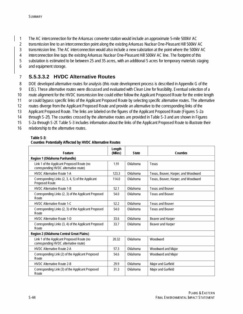
SUMMARY
PLAINS & EASTERN S-44 FINAL ENVIRONMENTAL IMPACT STATEMENT
The AC interconnection for the Arkansas converter station would include an approximate 5-mile 500kV AC 1 transmission line to an interconnection point along the existing Arkansas Nuclear One-Pleasant Hill 500kV AC 2 transmission line. The AC interconnection would also include a new substation at the point where the 500kV AC 3 interconnection line taps the existing Arkansas Nuclear One-Pleasant Hill 500kV AC line. The footprint of this 4 substation is estimated to be between 25 and 35 acres, with an additional 5 acres for temporary materials staging 5 and equipment storage. 6
S.5.3.3.2 HVDC Alternative Routes 7 DOE developed alternative routes for analysis (this route development process is described in Appendix G of the 8 EIS). These alternative routes were discussed and evaluated with Clean Line for feasibility. Eventual selection of a 9 route alignment for the HVDC transmission line could either follow the Applicant Proposed Route for the entire length 10 or could bypass specific links of the Applicant Proposed Route by selecting specific alternative routes. The alternative 11 routes diverge from the Applicant Proposed Route and provide an alternative to the corresponding links of the 12 Applicant Proposed Route. The links are labeled on the figures of the Applicant Proposed Route (Figures S-2a 13 through S-2f). The counties crossed by the alternative routes are provided in Table S-3 and are shown in Figures 14 S-2a through S-2f. Table S-3 includes information about the links of the Applicant Proposed Route to illustrate their 15 relationship to the alternative routes. 16
Table S-3: Counties Potentially Affected by HVDC Alternative Routes
Feature Length (Miles) State Counties
Region 1 (Oklahoma Panhandle) Link 1 of the Applicant Proposed Route (no corresponding HVDC alternative route)
1.91 Oklahoma Texas
HVDC Alternative Route 1-A 123.3 Oklahoma Texas, Beaver, Harper, and Woodward Corresponding Links (2, 3, 4, 5) of the Applicant Proposed Route
114.0 Oklahoma Texas, Beaver, Harper, and Woodward
HVDC Alternative Route 1-B 52.1 Oklahoma Texas and Beaver Corresponding Links (2, 3) of the Applicant Proposed Route
54.0 Oklahoma Texas and Beaver
HVDC Alternative Route 1-C 52.2 Oklahoma Texas and Beaver Corresponding Links (2, 3) of the Applicant Proposed Route
54.0 Oklahoma Texas and Beaver
HVDC Alternative Route 1-D 33.6 Oklahoma Beaver and Harper Corresponding Links (3, 4) of the Applicant Proposed Route
33.7 Oklahoma Beaver and Harper
Region 2 (Oklahoma Central Great Plains) Link 1 of the Applicant Proposed Route (no corresponding HVDC alternative route)
20.32 Oklahoma Woodward
HVDC Alternative Route 2-A 57.3 Oklahoma Woodward and Major Corresponding Link (2) of the Applicant Proposed Route
54.6 Oklahoma Woodward and Major
HVDC Alternative Route 2-B 29.9 Oklahoma Major and Garfield Corresponding Link (3) of the Applicant Proposed Route
31.3 Oklahoma Major and Garfield
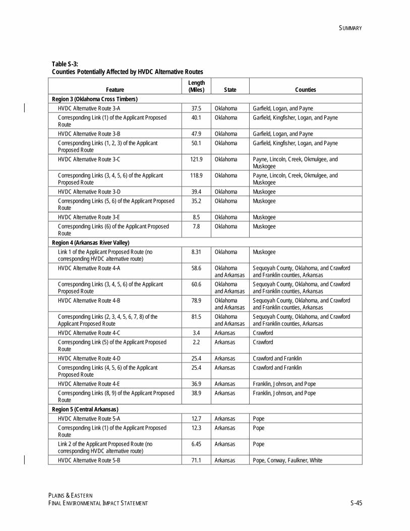
SUMMARY
PLAINS & EASTERN FINAL ENVIRONMENTAL IMPACT STATEMENT S-45
Table S-3: Counties Potentially Affected by HVDC Alternative Routes
Feature Length (Miles) State Counties
Region 3 (Oklahoma Cross Timbers) HVDC Alternative Route 3-A 37.5 Oklahoma Garfield, Logan, and Payne Corresponding Link (1) of the Applicant Proposed Route
40.1 Oklahoma Garfield, Kingfisher, Logan, and Payne
HVDC Alternative Route 3-B 47.9 Oklahoma Garfield, Logan, and Payne Corresponding Links (1, 2, 3) of the Applicant Proposed Route
50.1 Oklahoma Garfield, Kingfisher, Logan, and Payne
HVDC Alternative Route 3-C 121.9 Oklahoma Payne, Lincoln, Creek, Okmulgee, and Muskogee
Corresponding Links (3, 4, 5, 6) of the Applicant Proposed Route
118.9 Oklahoma Payne, Lincoln, Creek, Okmulgee, and Muskogee
HVDC Alternative Route 3-D 39.4 Oklahoma Muskogee Corresponding Links (5, 6) of the Applicant Proposed Route
35.2 Oklahoma Muskogee
HVDC Alternative Route 3-E 8.5 Oklahoma Muskogee Corresponding Links (6) of the Applicant Proposed Route
7.8 Oklahoma Muskogee
Region 4 (Arkansas River Valley) Link 1 of the Applicant Proposed Route (no corresponding HVDC alternative route)
8.31 Oklahoma Muskogee
HVDC Alternative Route 4-A 58.6 Oklahoma and Arkansas
Sequoyah County, Oklahoma, and Crawford and Franklin counties, Arkansas
Corresponding Links (3, 4, 5, 6) of the Applicant Proposed Route
60.6 Oklahoma and Arkansas
Sequoyah County, Oklahoma, and Crawford and Franklin counties, Arkansas
HVDC Alternative Route 4-B 78.9 Oklahoma and Arkansas
Sequoyah County, Oklahoma, and Crawford and Franklin counties, Arkansas
Corresponding Links (2, 3, 4, 5, 6, 7, 8) of the Applicant Proposed Route
81.5 Oklahoma and Arkansas
Sequoyah County, Oklahoma, and Crawford and Franklin counties, Arkansas
HVDC Alternative Route 4-C 3.4 Arkansas Crawford Corresponding Link (5) of the Applicant Proposed Route
2.2 Arkansas Crawford
HVDC Alternative Route 4-D 25.4 Arkansas Crawford and Franklin Corresponding Links (4, 5, 6) of the Applicant Proposed Route
25.4 Arkansas Crawford and Franklin
HVDC Alternative Route 4-E 36.9 Arkansas Franklin, Johnson, and Pope Corresponding Links (8, 9) of the Applicant Proposed Route
38.9 Arkansas Franklin, Johnson, and Pope
Region 5 (Central Arkansas) HVDC Alternative Route 5-A 12.7 Arkansas Pope Corresponding Link (1) of the Applicant Proposed Route
12.3 Arkansas Pope
Link 2 of the Applicant Proposed Route (no corresponding HVDC alternative route)
6.45 Arkansas Pope
HVDC Alternative Route 5-B 71.1 Arkansas Pope, Conway, Faulkner, White
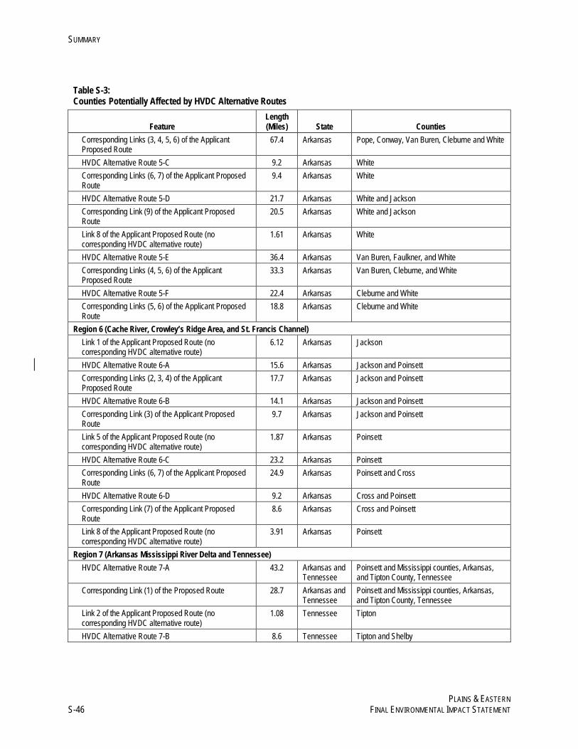
SUMMARY
PLAINS & EASTERN S-46 FINAL ENVIRONMENTAL IMPACT STATEMENT
Table S-3: Counties Potentially Affected by HVDC Alternative Routes
Feature Length (Miles) State Counties
Corresponding Links (3, 4, 5, 6) of the Applicant Proposed Route
67.4 Arkansas Pope, Conway, Van Buren, Cleburne and White
HVDC Alternative Route 5-C 9.2 Arkansas White Corresponding Links (6, 7) of the Applicant Proposed Route
9.4 Arkansas White
HVDC Alternative Route 5-D 21.7 Arkansas White and Jackson Corresponding Link (9) of the Applicant Proposed Route
20.5 Arkansas White and Jackson
Link 8 of the Applicant Proposed Route (no corresponding HVDC alternative route)
1.61 Arkansas White
HVDC Alternative Route 5-E 36.4 Arkansas Van Buren, Faulkner, and White Corresponding Links (4, 5, 6) of the Applicant Proposed Route
33.3 Arkansas Van Buren, Cleburne, and White
HVDC Alternative Route 5-F 22.4 Arkansas Cleburne and White Corresponding Links (5, 6) of the Applicant Proposed Route
18.8 Arkansas Cleburne and White
Region 6 (Cache River, Crowley’s Ridge Area, and St. Francis Channel) Link 1 of the Applicant Proposed Route (no corresponding HVDC alternative route)
6.12 Arkansas Jackson
HVDC Alternative Route 6-A 15.6 Arkansas Jackson and Poinsett Corresponding Links (2, 3, 4) of the Applicant Proposed Route
17.7 Arkansas Jackson and Poinsett
HVDC Alternative Route 6-B 14.1 Arkansas Jackson and Poinsett Corresponding Link (3) of the Applicant Proposed Route
9.7 Arkansas Jackson and Poinsett
Link 5 of the Applicant Proposed Route (no corresponding HVDC alternative route)
1.87 Arkansas Poinsett
HVDC Alternative Route 6-C 23.2 Arkansas Poinsett Corresponding Links (6, 7) of the Applicant Proposed Route
24.9 Arkansas Poinsett and Cross
HVDC Alternative Route 6-D 9.2 Arkansas Cross and Poinsett Corresponding Link (7) of the Applicant Proposed Route
8.6 Arkansas Cross and Poinsett
Link 8 of the Applicant Proposed Route (no corresponding HVDC alternative route)
3.91 Arkansas Poinsett
Region 7 (Arkansas Mississippi River Delta and Tennessee) HVDC Alternative Route 7-A 43.2 Arkansas and
Tennessee Poinsett and Mississippi counties, Arkansas, and Tipton County, Tennessee
Corresponding Link (1) of the Proposed Route 28.7 Arkansas and Tennessee
Poinsett and Mississippi counties, Arkansas, and Tipton County, Tennessee
Link 2 of the Applicant Proposed Route (no corresponding HVDC alternative route)
1.08 Tennessee Tipton
HVDC Alternative Route 7-B 8.6 Tennessee Tipton and Shelby
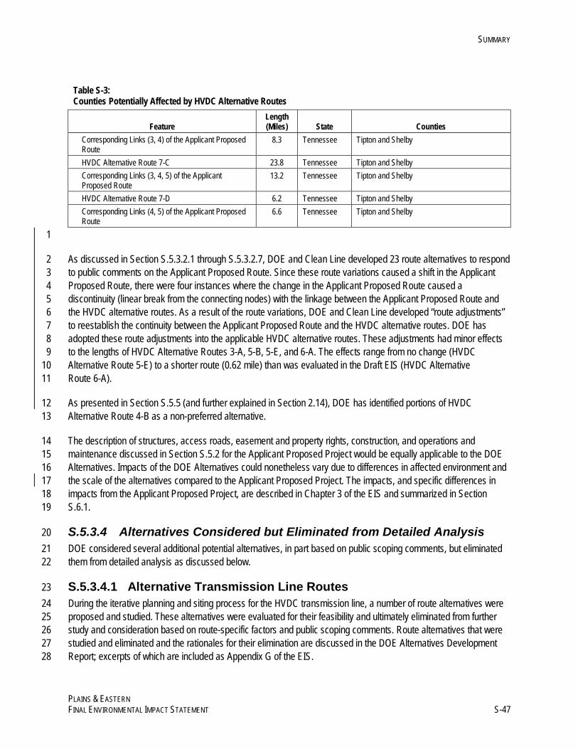
SUMMARY
PLAINS & EASTERN FINAL ENVIRONMENTAL IMPACT STATEMENT S-47
Table S-3: Counties Potentially Affected by HVDC Alternative Routes
Feature Length (Miles) State Counties
Corresponding Links (3, 4) of the Applicant Proposed Route
8.3 Tennessee Tipton and Shelby
HVDC Alternative Route 7-C 23.8 Tennessee Tipton and Shelby Corresponding Links (3, 4, 5) of the Applicant Proposed Route
13.2 Tennessee Tipton and Shelby
HVDC Alternative Route 7-D 6.2 Tennessee Tipton and Shelby Corresponding Links (4, 5) of the Applicant Proposed Route
6.6 Tennessee Tipton and Shelby
1
As discussed in Section S.5.3.2.1 through S.5.3.2.7, DOE and Clean Line developed 23 route alternatives to respond 2 to public comments on the Applicant Proposed Route. Since these route variations caused a shift in the Applicant 3 Proposed Route, there were four instances where the change in the Applicant Proposed Route caused a 4 discontinuity (linear break from the connecting nodes) with the linkage between the Applicant Proposed Route and 5 the HVDC alternative routes. As a result of the route variations, DOE and Clean Line developed “route adjustments” 6 to reestablish the continuity between the Applicant Proposed Route and the HVDC alternative routes. DOE has 7 adopted these route adjustments into the applicable HVDC alternative routes. These adjustments had minor effects 8 to the lengths of HVDC Alternative Routes 3-A, 5-B, 5-E, and 6-A. The effects range from no change (HVDC 9 Alternative Route 5-E) to a shorter route (0.62 mile) than was evaluated in the Draft EIS (HVDC Alternative 10 Route 6-A). 11
As presented in Section S.5.5 (and further explained in Section 2.14), DOE has identified portions of HVDC 12 Alternative Route 4-B as a non-preferred alternative. 13
The description of structures, access roads, easement and property rights, construction, and operations and 14 maintenance discussed in Section S.5.2 for the Applicant Proposed Project would be equally applicable to the DOE 15 Alternatives. Impacts of the DOE Alternatives could nonetheless vary due to differences in affected environment and 16 the scale of the alternatives compared to the Applicant Proposed Project. The impacts, and specific differences in 17 impacts from the Applicant Proposed Project, are described in Chapter 3 of the EIS and summarized in Section 18 S.6.1. 19
S.5.3.4 Alternatives Considered but Eliminated from Detailed Analysis 20 DOE considered several additional potential alternatives, in part based on public scoping comments, but eliminated 21 them from detailed analysis as discussed below. 22
S.5.3.4.1 Alternative Transmission Line Routes 23 During the iterative planning and siting process for the HVDC transmission line, a number of route alternatives were 24 proposed and studied. These alternatives were evaluated for their feasibility and ultimately eliminated from further 25 study and consideration based on route-specific factors and public scoping comments. Route alternatives that were 26 studied and eliminated and the rationales for their elimination are discussed in the DOE Alternatives Development 27 Report; excerpts of which are included as Appendix G of the EIS. 28
SUMMARY
PLAINS & EASTERN S-48 FINAL ENVIRONMENTAL IMPACT STATEMENT
Additional route alternatives (with varying degrees of detail) were provided as public comments on the Draft EIS. 1 DOE applied routing criteria in evaluating each request and recommendation for a route variation, including technical 2 feasibility, potential impacts, and location relative to the 1,000-foot-wide corridor and representative ROW analyzed in 3 the Draft EIS. After completing these evaluations, DOE chose to carry forward 23 of the recommended changes to 4 the Applicant Proposed Route in this Final EIS. In one case, DOE chose to carry forward both the route variation and 5 the corresponding segment of the Applicant Proposed Route for analysis in the Final EIS. DOE dismissed other 6 recommendations because they were not feasible, would result in potentially more adverse effects, or any overall 7 reduction in potential environmental impacts was negligible. For example, DOE dismissed two route variations 8 proposed in public comments from further consideration for Region 5, Link 9 because both variations would be closer 9 to residences than the original Applicant Proposed Route. One of the route variations would be located in more areas 10 of potential occurrence of the Indiana bat than the original Applicant Proposed Route. The other route variation would 11 have potential greater impacts to wetlands compared with the original Applicant Proposed Route. The rationale for 12 the dismissal of individual routing requests is documented in Appendix Q. 13
S.5.3.4.2 Underground HVDC Transmission Line 14 During public scoping and in comments received on the Draft EIS, some commenters suggested that the 15 transmission line be installed underground for either the entire length or for discrete segments to minimize visual 16 impacts associated with construction and operations and maintenance. Based on the analysis summarized below, 17 DOE concluded that undergrounding the Project (all or portions thereof) is not a reasonable alternative and has 18 eliminated it from further analysis. 19
HVDC technology and the voltage of 600kV were identified for the Project to meet the requirements to deliver 3,500–20 4,000MW of renewable energy at a competitive cost and meet the objectives and criteria of Section 1222 of the 21 EPAct 2005. To date, underground electric transmission cable technology is not commercially available at the very 22 high voltage and capacity levels (i.e., ±600kV and 3,500 to 4,000MW) planned for the Project. HVDC transmission at 23 600kV exhibits electrical characteristics that minimize electrical losses over long distances. If the line voltage for the 24 Project were reduced, the Project would not deliver the planned capacity in Tennessee. The highest rated proposed 25 cable system in the world at ±600kV is the Western Link Project in the United Kingdom, with a capacity of 2,200MW, 26 and a distance of about 260 miles (418km). This submarine project is under construction and, at present, is expected 27 to be in operation in 2016. The Western Link Project represents the limits of the application of current commercially 28 available cable technology to an undergrounding option. 29
While there is research underway for underground, high-voltage transmission cable technology that could 30 conceivably be applied to the voltage and capacity levels of the Project, this research has yet to produce 31 commercially available, proven technology, and DOE does not foresee that such technology will become available 32 within the time frame for construction of the Project. Furthermore, because such technology is not available, the costs 33 for implementing underground HVDC technology of the voltage and capacity proposed for the Project are unknown. 34
In summary, based on current information, even if such technology were to become available, other constraints 35 would make it infeasible to install a conductor (i.e., a transmission line) of this voltage and capacity underground. 36 Such conductors would be significantly larger than the conductor planned for the Project (requiring a 5-inch-diameter 37 conductor on approximately 4,500 spools weighing 66 tons each) that cannot be directly buried. They must be 38 mechanically protected by being installed within a buried duct bank, conduit, or tunnel. Frequent access points would 39 be required from the surface to allow for splicing, monitoring, and maintenance. Heat dissipation from the 40
SUMMARY
PLAINS & EASTERN FINAL ENVIRONMENTAL IMPACT STATEMENT S-49
underground conductors would be a significant challenge to the installation. Also, the large insulation requirements 1 would result in extreme weights for an underground conductor relative to an overhead conductor, so only short 2 segments could be installed at any one time, significantly increasing the cost and time required for completing the 3 construction. The diagnosis and repair of outages could be time-consuming, which would affect emergency response 4 times, and could result in additional ground disturbance and excavation to locate and repair the problems. 5
S.5.3.4.3 Local Generation and Distribution 6 During public scoping, commenters suggested utilizing distributed generation as an alternative to the Project. 7 Distributed generation involves the use of small-scale power generation technologies that are usually installed at or 8 near the location of the load being served by the generated power. Distributed generation does not require long-9 range transmission lines. Distributed generation systems range in size from approximately 5 kilowatts to 10MW; in 10 contrast, utility-scale generation ranges from 10MW to more than 1,000MW per site. Examples of distributed 11 generation resource technologies include residential and roof-top photovoltaic, energy storage devices, 12 microturbines, and fuel cells. 13
This alternative was eliminated from further analysis because Section 1222 of the EPAct does not authorize the 14 Secretary of Energy to participate with other entities in distributed generation, and the alternative does not meet the 15 DOE-issued RFP for new or upgraded transmission projects. As such, the alternative would not meet the purpose 16 and need for agency action. DOE has established policies and programs related to distributed generation 17 (http://www.energy.gov/eere/slsc/renewable-energy-distributed-generation-policies-and-programs). 18
S.5.3.4.4 Energy Conservation Programs 19 During public scoping, commenters suggested energy conservation programs as an alternative to the Project. 20 Commenters suggested that mandatory conservation and demand response programs be used to eliminate the need 21 for more generation and transmission. This alternative was eliminated from detailed consideration because Section 22 1222(b) of the EPAct does not authorize the Secretary of Energy to participate with other entities in energy 23 conservation programs. As such, the alternative would not meet the purpose and need for agency action. Further, the 24 alternative would not satisfy the eligibility criteria in the DOE-issued RFP for new or upgraded transmission projects. 25 DOE has established policies and programs related to energy conservation programs 26 (http://www.energy.gov/eere/efficiency). 27
S.5.4 Connected Actions 28 Connected actions are those that are “closely related” to the proposal. Actions are considered connected if they 29 automatically trigger other actions that may require environmental impact statements, cannot or will not proceed 30 unless other actions have been taken previously or simultaneously, or are interdependent parts of a larger action and 31 depend on the larger action for their justification (40 CFR 1508.25). The potential environmental impacts resulting 32 from the connected actions are analyzed in the EIS and summarized in Section 2.11. 33
S.5.4.1 Wind Energy Generation 34 The construction and operation of reasonably foreseeable wind power facilities are evaluated as connected actions in 35 the Plains & Eastern EIS. Wind power facilities that would interconnect with the Project are anticipated to be located 36 in parts of the Oklahoma Panhandle and Texas Panhandle within an approximately 40-mile radius of the Oklahoma 37 converter station. The Applicant based the 40-mile radius assumption on preliminary studies of engineering 38
SUMMARY
PLAINS & EASTERN S-50 FINAL ENVIRONMENTAL IMPACT STATEMENT
constraints and wind resource data, industry knowledge, and economic feasibility. The Applicant anticipates that 1 these wind generators would be the primary customers using the transmission capacity of the Plains & Eastern 2 transmission line. To achieve full utilization of the 3,500MW delivery capacity of the Applicant Proposed Project, the 3 Applicant anticipates actual wind farm build-out to be approximately 4,000MW. With the addition of the Arkansas 4 converter station alternative, the Applicant anticipates the delivery capacity of the Project to increase to 4,000MW, 5 and associated wind farm build-out to be approximately 4,550MW (Clean Line 20146). An analysis of the wind 6 resource in Oklahoma’s Panhandle region by the National Renewable Energy Laboratory shows that large areas of 7 wind resources with average annual wind speeds greater than 8 meters/second are prevalent in that part of the state. 8
Neither the Applicant nor DOE knows the exact location of wind power facilities that would be connected to the 9 Project. However, it is reasonably foreseeable that future wind farms would be located in a reasonable proximity to 10 the Project’s Oklahoma converter station and in areas with high wind resource potential and suitable land use(s). 11 This EIS provides an analysis of impacts from wind development within an area of approximately 40 miles of the 12 Oklahoma converter station. Where construction and operation of individual wind power facilities require permits or 13 authorizations, site-specific environmental review, possibly including NEPA review, may be conducted prior to the 14 construction and operation of individual wind farm projects. 15
S.5.4.2 Related Substation and Transmission Upgrades 16 In addition to the transmission lines and related facilities analyzed as part of the Project, the EIS also analyzes facility 17 additions and upgrades to existing third-party transmission systems that would be required to enable the Project to 18 transmit power. The additions and upgrades in Oklahoma and Tennessee are evaluated as connected actions in the 19 Plains & Eastern EIS. No connected actions are currently identified as associated with substation or transmission 20 upgrades in Arkansas. If, in the future, network upgrades were identified, they would likely be similar to those 21 discussed for TVA, below. 22
Oklahoma 23 The Applicant Proposed Project includes construction and operations and maintenance of a converter station in 24 Texas County, Oklahoma. The Oklahoma converter station would be interconnected to the existing transmission 25 system. This interconnection is necessary to enable the AC to DC conversion process within the Oklahoma converter 26 station. The interconnection between the proposed Oklahoma converter station and the SPS system would be 27 controlled to a nominal value of zero (0) MW, meaning that there would be no net energy exchange. Based on the 28 SPS analysis, a new substation would be necessary to accommodate the interconnection due to space constraints at 29 the existing 345kV Hitchland Substation. To alleviate these space constraints, SPS has proposed a new substation 30 nearby, tentatively named “Optima.” This new substation, which represents the connected action, would be located 31 within a few miles of the Oklahoma converter station in Texas County, Oklahoma, within the area identified on Figure 32 2.1-3 in Appendix A of the EIS as the AC Interconnection Siting Area. Additional background and details are provided 33 in Section 2.2.1.1. 34
Arkansas 35 A DOE Alternative would include construction and operations and maintenance of an intermediate converter station 36 in Arkansas to enable injection and delivery of up to 500MW of power into the Arkansas electrical grid. Clean Line 37 6 Clean Line Energy Partners LLC. 2014. Wind Generation Technical Report for the Plains and Eastern Transmission Line
Project. Prepared by Clean Energy Partners LLC for the Department of Energy pursuant to 10 CFR 1021.215(b)(2). March 2014. (Available on EIS Reference CD.)
SUMMARY
PLAINS & EASTERN FINAL ENVIRONMENTAL IMPACT STATEMENT S-51
selected the Arkansas Nuclear One-Pleasant Hill 500kV Point of Interconnection in an attempt to avoid the need for 1 additional upgrades to the surrounding transmission system and to accommodate a 500MW injection. The 2 Midcontinent Independent System Operator (MISO) performed a feasibility study of the request and delivered results 3 to Clean Line in February 2014. The purpose of this feasibility study was to identify the cost to Clean Line to enter 4 into the Definitive Planning Phase, which consists of several steps including a system impact study and an 5 interconnection facilities study. These studies would begin to identify the upgrades required to MISO’s system, if any, 6 and the next steps for Clean Line to proceed with the Project. If, in the future, network upgrades were identified, they 7 would likely be similar to those discussed for TVA below. 8
Tennessee 9 The Applicant Proposed Project includes construction and operations and maintenance of a converter station in 10 Shelby County, Tennessee, to enable injection of up to 3,500MW of power into the Shelby Substation. TVA 11 completed its Interconnection System Impact Study to determine whether any upgrades (or modifications) to its 12 transmission system would be necessary to protect grid reliability while accommodating Clean Line’s request for 13 interconnection at 3,500MW. TVA’s Interconnection System Impact Study has identified the following connected 14 actions as necessary to enable the injection of 3,500MW from the Plains & Eastern Clean Line: (a) upgrades to 15 existing infrastructure and (b) construction of a new 500kV AC transmission line, approximately 37 miles long, in 16 western Tennessee, including necessary modifications to existing substations on the terminal ends of the new line. 17 Upgrades to existing infrastructure would include upgrading terminal equipment at three existing 500kV substations 18 and six existing 161kV substations, making appropriate upgrades7 to increase heights on 16 existing 161kV 19 transmission lines to increase line ratings, and replacing the conductors on 8 existing 161kV transmission lines. It 20 should be noted that the region of influence (ROI) for the substation upgrades (which are included in the Applicant 21 Proposed Project) would occur within the Tennessee Converter Station Siting Area and more specifically within the 22 Shelby Substation. The ROI for the network upgrades, and in particular TVA's future 500kV transmission line, cannot 23 be fully determined at this time. 24
The total length of existing transmission lines that could require some degree of upgrade is approximately 350 miles; 25 most of these lines are located in central and western Tennessee. However, the upgrades would likely not be 26 necessary along the full length of each line; therefore, the total length of existing transmission lines requiring 27 modification would be less than 350 miles. The detailed identification of the necessary upgrades to each transmission 28 line and construction of a new transmission line (as discussed above) is the subject of an interconnection facilities 29 study, which should be completed in 2016. 30
S.5.5 Agency Preferred Alternative 31 The proposed Plains & Eastern transmission line represents high-voltage transmission facilities that would make 32 possible the development of valuable wind resources in the Oklahoma and Texas Panhandle regions by providing 33 HVDC transmission capability to deliver 3,500–4,000MW of electricity to the Mid-South and Southeast regions of the 34 United States (depending on selected alternatives). DOE has evaluated the Proposed Action of whether to participate 35 under Section 1222 of the EPAct, acting through and in consultation with the Administrator of Southwestern, in the 36 Applicant Proposed Project or DOE Alternatives in one or more of the following ways: designing, developing, 37 constructing, operating, maintaining, or owning a new electric power transmission facility and related facilities located 38
7 Most upgrades to existing transmission lines would occur in central and western Tennessee.
SUMMARY
PLAINS & EASTERN S-52 FINAL ENVIRONMENTAL IMPACT STATEMENT
within certain states in which Southwestern operates, namely Oklahoma, Arkansas, and, possibly Texas. As 1 identified throughout Chapter 2, there are several elements that make up the Project. These elements include: 2
• Applicant Proposed Project 3 o Oklahoma Converter Station and AC Interconnection 4 o Tennessee Converter Station and AC Interconnection 5 o AC Collection System 6 o HVDC Applicant Proposed Route (through Regions 1–7) 7
• DOE Alternatives 8 o Arkansas Converter Station and AC Interconnection 9 o HVDC alternative routes (through Regions 1–7) 10
CEQ regulations at 40 CFR 1502.14(e) require an agency to identify its preferred alternative in the Final EIS. While 11 developing the Final EIS, DOE considered the alternatives analyzed in the Draft EIS, the comparison of potential 12 impacts for each resource area, and input received on the Draft EIS. DOE has coordinated with the various 13 cooperating agencies to determine the preferred alternatives for each of the Project elements. The following 14 paragraphs present the DOE preferred alternative for each of the Project elements and the bases for its identification. 15 DOE’s identification of a preferred alternative in an EIS does not guarantee that such an alternative will be the 16 alternative selected in DOE’s ROD. Rather, identification of the preferred alternative serves to give the public notice 17 as to which alternative DOE currently favors. The ROD, which would be signed no earlier than 30 days after the EPA 18 Notice of Availability for the Final EIS is published in the Federal Register, would document DOE’s decision. 19
S.5.5.1 Participation in the Applicant Proposed Project 20 Based on the information presented in the Final EIS, DOE has identified participation as its preferred alternative. 21
Parallel with the NEPA process, DOE is evaluating Clean Line’s application under Section 1222 of the EPAct. This 22 non-NEPA evaluation includes, but is not limited to, evaluating the application against statutory criteria and technical 23 and financial viability. An outcome of this evaluation could be a Participation Agreement between Clean Line and 24 DOE, which would define under what conditions DOE would participate with Clean Line and, if applicable, would 25 include any stipulations or requirements that resulted from this environmental review under NEPA. 26
S.5.5.1.1 Oklahoma Converter Station and AC Interconnection 27 The Applicant Proposed Project would require an AC/DC converter station at the western terminus of the 28 transmission line. The Oklahoma Converter Station Siting Area is an approximate 620-acre area in Texas County, 29 Oklahoma, within which the converter station and associated AC switchyard (45 to 70 acres total) and access road or 30 roads would be sited. The construction and operations and maintenance of the Oklahoma converter station within 31 this siting area is DOE’s preferred alternative for a converter station at the western terminus of the transmission line. 32
The Oklahoma converter station would require a connection to the SPP electric grid. Clean Line has proposed a 33 double-circuit 345kV AC transmission line up to 3 miles in length to interconnect the proposed converter station with 34 a planned Xcel Energy/Southwest Public Service Company substation referred to as Optima. The construction and 35 operations and maintenance of this interconnection is DOE’s preferred alternative for connecting the proposed 36 Oklahoma converter station to the existing electric grid. 37
SUMMARY
PLAINS & EASTERN FINAL ENVIRONMENTAL IMPACT STATEMENT S-53
S.5.5.1.2 Tennessee Converter Station and AC Interconnection 1 The Applicant Proposed Project would require an AC/DC converter station at the eastern terminus of the 2 transmission line. The Tennessee Converter Station Siting Area is an approximate 220-acre area in Shelby County, 3 Tennessee, within which the converter station and associated AC switchyard (45 to 70 acres total) and access road 4 or roads would be sited. The AC interconnection would be a direct connection between the converter station and the 5 existing Shelby Substation. Consistent with Section 1222 of the EPAct, DOE's participation in the Applicant Proposed 6 Project or DOE Alternatives would be limited to states in which Southwestern operates, namely, Oklahoma, 7 Arkansas, and, possibly, Texas, but not Tennessee. Consequently, DOE would not participate in the portions of the 8 Applicant Proposed Project or DOE Alternatives that would be sited in Tennessee. As such, when making its decision 9 on whether to participate in the Project under Section 1222, DOE would not select a particular converter station 10 location in Tennessee. The alternatives analysis of the Project components in Tennessee may be relied upon, 11 however, by other agencies with permitting or authorization decisions for the Project in Tennessee, including, but not 12 limited to, TVA and USACE. Therefore, DOE does not have a preferred alternative for the Tennessee converter 13 station and AC interconnection. 14
S.5.5.1.3 AC Collection System 15 Clean Line would construct between four and six AC collection transmission lines within a 40-mile radius from the 16 Oklahoma converter station to collect energy from generation resources in the Oklahoma and Texas Panhandle 17 regions. The collection system would consist of 345kV AC transmission lines that would extend from the converter 18 station to future wind farms. These wind farms, which would likely be established in the wind development zones 19 (WDZs) evaluated in the EIS as connected actions, have not been established and their exact locations cannot be 20 known at this time. DOE evaluated 13 possible route alternatives for these AC collection transmission lines to fully 21 evaluate their potential environmental impacts. DOE’s preferred alternative is for the Applicant to construct between 22 four and six AC collection transmission lines within a 40-mile radius from the Oklahoma converter station; the specific 23 locations of these transmission lines cannot be known at this time and would depend on the locations of future wind 24 farms in this area. 25
S.5.5.1.4 Arkansas Converter Station and AC Interconnection 26 Based on comments received during the scoping period, DOE identified and evaluated an alternative converter 27 station in Arkansas. The Arkansas converter station would be an intermediate converter station that would not 28 replace either of the other converter stations in Oklahoma or Tennessee. This alternative converter station would be 29 similar to, but smaller than, the Oklahoma and Tennessee converter stations and would allow the delivery of 500MW 30 of power to the electric grid in Arkansas. The Arkansas Converter Station Siting Area is an approximate 360-acre 31 area in Pope County, Arkansas, within which the converter station and associated AC switchyard (20 to 35 acres 32 total) and access road or roads would be sited. The construction and operations and maintenance of the Arkansas 33 converter station within this siting area is DOE’s preferred alternative for an intermediate converter station. 34
The Arkansas converter station would require a connection to the existing electric grid in Arkansas. The 35 interconnection would include an approximate 5-mile 500kV AC transmission line to an interconnection point along 36 the existing Arkansas Nuclear One-Pleasant Hill 500kV AC transmission line. The interconnection would include a 37 new substation (footprint of 25–35 acres) at the point where the 500kV AC interconnection line taps the existing 38 Arkansas Nuclear One-Pleasant Hill 500kV line. The construction and operations and maintenance of this 39
SUMMARY
PLAINS & EASTERN S-54 FINAL ENVIRONMENTAL IMPACT STATEMENT
interconnection is DOE’s preferred alternative for connecting the proposed Arkansas converter station to the existing 1 electric grid. 2
S.5.5.1.5 HVDC Transmission Line Routes 3 There is no “impact-free” routing choice for a large transmission line. In some regions of the Project, where there are 4 multiple resource conflicts, the HVDC alternative routes impact certain resources differently, and some alternative 5 routes were included in the analysis to emphasize protection of one resource or land value over another. The 6 information in Table 2.6-3 of Chapter 2 provides a summary of potential impacts for the HVDC transmission line by 7 resource and highlights substantive differences between the Applicant Proposed Route, route variations, and HVDC 8 alternative routes. 9
After EIS scoping and during the development of the Draft EIS, DOE and Clean Line entered into a Tier IV route 10 development process for the Applicant Proposed Route and the HVDC alternative routes. This process, as 11 documented in Section 2.3 and the DOE Alternatives Development Report (Appendix G), included the establishment 12 of General and Technical guidelines to focus the evaluation of the various route alternatives. The General Guidelines 13 were intended to minimize conflicts with existing resources, developed areas, and existing incompatible 14 infrastructure; to maximize opportunities for paralleling existing compatible infrastructure; and to take into 15 consideration land use and other factors affecting route identification. The General Guidelines included the following: 16
• Utilize existing linear corridors to the extent practicable 17 • Utilize areas with land uses/land cover that are consistent or compatible with linear utility uses, such as existing 18
utility corridors and open lands, to the extent practicable 19 • Avoid existing residences 20 • Avoid nonresidential structures, including barns, garages, and commercial buildings 21 • Minimize interference with the use and operation of existing schools, known places of worship, and existing 22
facilities used for cultural, historical, and recreational purposes 23 • Avoid cemeteries or known burial places 24 • Minimize adverse effects to economic activities (e.g., impacts to existing residences, businesses and developed 25
areas) 26 • Minimize crossing of designated public resource lands, including, but not limited to, national and state forests 27
and parks, large camps and other recreation lands, designated battlefields or other designated historic resources 28 and sites, and state-owned wildlife management areas 29
• Minimize crossings of tribal trust lands and allotments 30 • Minimize the number and length of crossings of large lakes, major rivers, large wetland complexes, or other 31
sensitive water resources 32 • Minimize adverse effects on protected species habitat and on other identified sensitive natural resources (e.g., 33
forested areas, native prairies, and other areas as identified by Natural Heritage Commissions) 34 • Minimize visibility of transmission lines from residential areas and visually sensitive public locations (e.g., public 35
parks, scenic routes or trails, and designated Wild and Scenic Rivers) 36 • Avoid areas of past environmental contamination to the extent practicable 37 • Minimize route length, circuitry, special design requirements, and impractical construction requirements 38
The Technical Guidelines were specific to the Project and were based on technical limitations related to the design, 39 ROW requirements, or reliability concerns. The Technical Guidelines included the following: 40
SUMMARY
PLAINS & EASTERN FINAL ENVIRONMENTAL IMPACT STATEMENT S-55
• Minimize the crossing of transmission lines of 345kV or above 1 • Minimize paralleling corridors with more than one existing circuit of 345kV or above 2 • Maintain 200 feet of centerline-to-centerline separation when paralleling existing transmission lines of 345kV or 3
above 4 • Maintain 150 feet of centerline-to-centerline separation when paralleling 138kV or lower voltage transmission 5
lines 6 • Minimize turning angles in the transmission line greater than 65 degrees 7 • Minimize the length of the transmission line located on soils sloped more than 20 percent 8 • Minimize underbuild or double circuit arrangements with existing AC infrastructure 9
The route alternatives analyzed in the Draft EIS were identified based on these guidelines. A detailed discussion of 10 the route development and basis for identification of the Applicant Proposed Route is included in Section 2.3.1 and 11 Appendix G. To respond to public comments on the Draft EIS, DOE and Clean Line developed 23 route variations 12 (as described in Sections 2.3.1 and 2.4.2.1 through 2.4.2.7). These route variations were developed with the intent of 13 reducing land use conflicts or minimizing potential environmental impacts of the Applicant Proposed Route from the 14 levels of impacts considered in the Draft EIS. In all but one instance, the route variations replaced their 15 corresponding segments of the Applicant Proposed Route. This exception (Region 4, Applicant Proposed Route Link 16 3, Variation 2) was carried forward as an additional alternative for comparative analysis in this Final EIS with the 17 corresponding segment of the Applicant Proposed Route. 18
Identification of the preferred route for the HVDC transmission line depends on two primary factors: 1) the Applicant 19 Proposed Route evaluated in the Draft EIS was initially identified from among the initial route alternatives because it 20 minimized potential environmental impacts (as detailed in Appendix G), and 2) the Applicant Proposed Route as 21 analyzed in this Final EIS includes route variations that were developed to incorporate feedback from landowners 22 with the intent of reducing land use conflicts and minimizing environmental impacts. Considering these factors, the 23 Applicant Proposed Route (as presented in the Final EIS) is DOE’s preferred route for the majority of the route from 24 the Oklahoma converter station to the Arkansas/Tennessee border. Consistent with Section 1222 of the EPAct, 25 DOE's participation in the Project would be limited to states in which Southwestern operates, namely, Oklahoma, 26 Arkansas, and, possibly, Texas, but not Tennessee. Consequently, DOE would not participate in any portion of the 27 Project that would be sited in Tennessee. As such, when making its decision on whether to participate in the Project 28 under Section 1222, DOE would not select an HVDC route alternative in Tennessee. Outside Tennessee, the only 29 exception to the Applicant Proposed Route, as DOE’s preferred route, is DOE’s identification of the route variation 30 (Region 4, Applicant Proposed Route Link 3, Variation 2) mentioned above to be a segment of the preferred route. 31 The basis for the identification of this route variation over the corresponding segment of the Applicant Proposed 32 Route includes the following: 1) the route variation crosses 32 percent fewer land parcels (17 versus 25); 2) the route 33 variation parallels more than twice the length of existing infrastructure, including transmission lines and roads (4.42 34 miles versus 1.85 miles); 3) the representative ROW of the route variation would be located within 500 feet of 8 fewer 35 residences (1 versus 9); and 4) the route variation would avoid a private airstrip whose operations could be impacted 36 by the Applicant Proposed Route. 37
Similarly, because DOE’s preferred route is the route alternative with the lowest potential for environmental impacts 38 when compared against the other HVDC route alternatives, it is also designated as the environmentally preferable 39 route alternative. While the No Action Alternative would avoid the environmental impacts identified in the EIS, 40
SUMMARY
PLAINS & EASTERN S-56 FINAL ENVIRONMENTAL IMPACT STATEMENT
adoption of this alternative would not meet DOE’s purpose and need as identified in Section 1.1, which is to 1 implement Section 1222 of the EPAct of 2005. 2
As mentioned earlier, the identification of the DOE’s preferred route in this Final EIS is not a DOE decision on the 3 overall HVDC route. DOE could select from any of the proposed route alternatives for that decision with one 4 exception: the portion of HVDC Alternative Route 4-B that would intersect the Ozark National Forest in Crawford 5 County, Arkansas, is considered non-preferred in the Final EIS as explained in Section 2.14.1.5. 6
DOE would still be able to select other portions of HVDC Alternative Route 4-B as segments of the HVDC 7 transmission line route if used in concert with other HVDC alternative routes in Region 4. For example, the western 8 segment of HVDC Alternative Route-4B could be used with 4-A, or the eastern portion of HVDC Alternative Route 4-9 B could be used with either 4-A or 4-D. 10
S.6. Potential Impacts 11
S.6.1 Direct and Indirect Impacts 12 The impacts analyzed in Chapter 3 of the Plains & Eastern EIS are summarized in the sections that follow. They 13 include a summary of potential environmental impacts from construction and operations of the proposed converter 14 stations, including the Arkansas converter station alternative, the AC collection system, AC interconnections, and the 15 HVDC transmission line, including any specific difference in impacts between the Applicant Proposed Route and the 16 HVDC alternative routes. Changes in potential impacts associated with the 23 route variations are described by 17 resource. Impacts from connected actions are also summarized below. 18
Impacts are presented for the following resources (which are in alphabetical order): Agriculture; Air Quality and 19 Climate Change; Electrical Environment; Environmental Justice; Geology, Paleontology, Minerals, and Soils; 20 Groundwater; Health, Safety, and Intentional Destructive Acts; Historic and Cultural Resources; Land Use; Noise; 21 Recreation; Socioeconomics; Special Status Wildlife, Fish, Aquatic Invertebrate, and Amphibian Species; Surface 22 Water; Transportation; Vegetation Communities and Special Status Plant Species; Visual Resources; Wetlands, 23 Floodplains, and Riparian Areas; and Wildlife, Fish, and Aquatic Invertebrates. 24
S.6.1.1 Analysis Methodology 25 The EIS defines the area potentially affected by the Project as the region of influence (ROI). The ROI extends 26 beyond the physical dimensions of the HVDC and AC transmission ROWs and converter station footprints. The 27 general ROI for the determination of potential direct and indirect impacts to most environmental resource areas 28 includes the following: 29
• Oklahoma Converter Station Siting Area: An approximate 620-acre area in Texas County, Oklahoma, within 30 which the Applicant proposes to site the Oklahoma converter station and associated AC switchyard (45 to 70 31 acres total) and access road(s). 32
• Oklahoma AC Interconnection Siting Area: An approximate 870-acre corridor within which the Applicant 33 proposes to site an AC transmission interconnection route from the Oklahoma converter station to the future 34 Optima Substation. 35

SUMMARY
PLAINS & EASTERN FINAL ENVIRONMENTAL IMPACT STATEMENT S-57
• AC Collection System: Thirteen 2-mile-wide corridors in Oklahoma (Beaver, Cimarron, and Texas counties) and 1 Texas (Hansford, Ochiltree, and Sherman counties) within which the Applicant anticipates that the AC Collection 2 System could be sited. 3
• Tennessee Converter Station Siting Area: An approximate 220-acre area located in Shelby County, Tennessee, 4 within which the Applicant proposes to site the Tennessee converter station and associated AC switchyard (45 to 5 70 acres total), access road(s), and the AC transmission interconnection, which would span between the 6 converter station and the adjacent existing Shelby Substation. 7
• HVDC Applicant Proposed Route: A 1,000-foot-wide corridor within which the Applicant proposes to site the 8 ROW for the HVDC transmission line between the Oklahoma converter station and the Tennessee converter 9 station. 10
The ROI for the DOE Alternatives consist of the following: 11
• Arkansas Converter Station Alternative Siting Area: An approximate 360-acre siting area located in Pope 12 County, Arkansas, within which the Arkansas converter station and associated AC switchyard (25 to 45 acres 13 total) and access road(s) could be sited. 14
• Arkansas AC Interconnection Siting Area: An approximate 660-acre corridor within which potential 500kV AC 15 transmission line(s) would be sited from the Arkansas converter station to an interconnection point(s) with an 16 existing 500kV AC transmission line. The interconnection would also require a 25- to 35-acre substation near the 17 tap with the existing Arkansas Nuclear One-Pleasant Hill 500kV AC transmission line, with another 5 acres for 18 material staging and equipment storage. 19
• HVDC Alternative Routes: A series of 1,000-foot-wide corridors which DOE has proposed as alternatives to the 20 HVDC Applicant Proposed Route within which the ROW for the HVDC transmission line could be sited. 21
The ROI for connected actions are described below: 22
• Wind Energy Generation ROI: Twelve WDZs were identified by the Applicant within approximately 40-miles of 23 the Oklahoma Converter Station Siting Area and within parts of the Oklahoma Panhandle and Texas Panhandle. 24 These WDZs exhibit adequate wind resource and are areas within which future development of wind energy 25 facilities would likely occur. The ROI for the 12 WDZs is approximately 1,385,000 acres in Oklahoma (Beaver, 26 Cimarron, and Texas counties) and Texas (Hansford, Ochiltree, and Sherman counties). 27
• Optima Substation ROI: The future SPS Optima Substation would be constructed within approximately 160 28 acres of land and would be located within a few miles of the Oklahoma converter station in Texas County, 29 Oklahoma. It would be partially located within the Oklahoma AC Interconnection Siting Area as shown on 30 Figure 2.1-3 (located in Appendix A of the EIS). 31
• TVA Upgrade ROI: TVA’s interconnection system impact study has identified the following as necessary to 32 accommodate the Plains & Eastern Clean Line HVDC interconnection: (a) upgrades to existing infrastructure 33 and (b) construction of a new 500kV AC transmission line, approximately 37 miles long, in western Tennessee, 34 including necessary modifications to existing substations on the terminal ends of the new line. Upgrades to 35 existing infrastructure would include upgrading terminal equipment at three existing 500kV substations and six 36 existing 161kV substations; making appropriate upgrades to increase heights on 16 existing 161kV AC 37 transmission lines to increase line ratings, and replacing the conductors on 8 existing 161kV AC transmission 38 lines (as described in Section 2.5.2). The ROI for the substation upgrades would occur within the Shelby 39 Substation. The ROI for the network upgrades, and in particular TVA's future 500kV AC transmission line, 40
SUMMARY
PLAINS & EASTERN S-58 FINAL ENVIRONMENTAL IMPACT STATEMENT
cannot be fully determined at this time. The ROW for the 500kV transmission line would occupy about 785 acres, 1 assuming a ROW width of 175 feet. The upgrades to existing substations are expected to take place within the 2 current substation boundaries and the upgrades to existing transmission lines, except for potential access roads, 3 are expected to take place within existing ROWs. 4
These ROIs have been expanded or modified on a resource specific basis where appropriate as described in certain 5 resource area sections below. Resources where the ROIs have been expanded or modified include these resources: 6 Air Quality and Climate Change, Environmental Justice, Groundwater, Surface Water, Special Status Wildlife, Fish, 7 Aquatic Invertebrate, and Amphibian Species, Socioeconomics, Transportation, and Visual Resources. For example, 8 the ROI for examination of socioeconomic impacts (Section 3.13) of the Project was expanded to encompass 9 counties surrounding the Project components so that impacts on economic conditions, agriculture, housing, and 10 community services could be evaluated. 11
The analyses of impacts for the HVDC Applicant Proposed Route, AC collection system, and HVDC alternative 12 routes are based on a representative 200-foot-wide ROW (100 feet on either side of a representative centerline). 13 Quantitative data regarding the resources that would be directly intersected by the representative 200-foot-wide 14 ROW are used as a representative example of potential impacts from a ROW within a given ROI. The resources that 15 could be affected by the Project vary throughout the 1,000-foot-wide corridor where the actual ROW could be 16 located. The representative ROW does not necessarily reflect where particular resources are most or least 17 concentrated, or an average. For example, the representative ROW avoids many homes and environmental 18 resources, and so moving the ROW within the 1,000-foot-wide corridor could result in environmental impacts different 19 from those described for the representative ROW. 20
By identifying the existing resources within a broader corridor or siting area, the analyses presented in this EIS 21 consider the full scope of the potential impacts from siting the Project facilities anywhere within their respective siting 22 areas or corridors. The final transmission line ROW could be located anywhere within the 1,000-foot-wide corridor 23 identified in this Final EIS. The final location would be determined following the completion of the NEPA process, 24 engineering design, and ROW acquisition activities. Determination of this final location is referred to as micrositing. 25 The micrositing of a transmission line ROW and the converter stations would require detailed engineering that 26 considers existing conditions; compliance with federal, state, and local permits and authorizations; and incorporation 27 of all EPMs developed by the Applicant. The potential impacts presented in the EIS would serve as one source 28 informing the siting of the HVDC and AC transmission line ROWs and converter stations. Further, the siting of the 29 four to six ROWs for the AC transmission lines that would be part of the AC collection system would also depend on 30 the final locations of the wind generation projects. The specific locations of those wind farms and transmission lines 31 to them would not be known until after completion of the EIS process (including issuance of DOE’s ROD) and closer 32 to the time of construction of the Project. 33
For the purpose of all analyses for the EIS, it is assumed that the Applicant would conduct each phase of the Project 34 in compliance with applicable federal, state and local laws, regulations and permits related to construction, operations 35 and maintenance, and decommissioning of the Project. Appendix C of the EIS presents an overview of potential 36 federal and state permits and consultation that could be required for construction of the Project. Local permits and 37 approvals may also be required for the Project. 38
SUMMARY
PLAINS & EASTERN FINAL ENVIRONMENTAL IMPACT STATEMENT S-59
The Applicant has developed general and resource-specific EPMs to avoid or minimize effects to environmental 1 resources during construction, operations and maintenance, and/or decommissioning of the Project. The Applicant 2 would identify certain areas as “environmentally sensitive” and implement relevant EPMs to avoid and/or minimize 3 adverse effects on these identified areas to the extent practicable. Environmentally sensitive areas may include 4 wetlands, certain water bodies, cultural resources, and wildlife habitat. The general EPMs are designed to minimize 5 environmental impacts across multiple resources. Other general EPMs address avian mortality, vegetation 6 management, herbicide use, transportation, road maintenance, hazardous materials, and other topics of concern. 7 The resource-specific EPMs include measures to protect land use; soils and agriculture; fish, vegetation, and wildlife; 8 and waters, wetlands, and floodplains. The complete list of EPMs is presented in Appendix F of the EIS. The EPMs 9 would be made binding through the ROD and terms of participation agreements between DOE and the Applicant. 10 The EPMs would be implemented through a combination of environmental-related plans; compliance with federal, 11 state, and local environmental regulations; and permitting requirements. The specific environmental-related plans 12 that the Applicant has identified and described in Appendix F include: 13
• Transportation and Traffic Management Plan 14 • Blasting Plan 15 • Restoration Plan 16 • Spill Prevention, Control and Countermeasures Plan 17 • Stormwater Pollution Prevention Plan 18 • Transmission Vegetation Management Plan 19 • Avian Protection Plan 20 • Construction Security Plan 21 • Cultural Resources Management Planning Documents including Historic Properties Treatment Plan and 22
Unanticipated Discoveries Plan 23
In some resource sections, DOE has identified best management practices (BMPs) that could further avoid or 24 minimize potential adverse impacts. 25
S.6.1.2 Agricultural Resources 26 Construction could affect livestock grazing by temporarily restricting livestock from grazing within or accessing the 27 ROW in discrete locations during times that the ROW is restricted during construction for safety reasons. Yields from 28 cropland and pasture/hay could be temporarily affected in the construction areas. Potential temporary impacts to 29 center-pivot irrigation could occur, primarily in Regions 1, 2, 6, and 7, during construction. Also during construction, 30 access roads, temporary work areas, and other graded areas could temporarily disrupt the slope and flow patterns of 31 water on flood-irrigated fields. Transmission structures may interfere with farming equipment and aerial crop 32 spraying, which may reduce crop yields. 33
Maintenance of the Project facilities may occasionally disrupt agricultural activities and production on a localized 34 basis. Potential indirect impacts to agricultural production from interference with aerial applications of fertilizer, 35 insecticide, and herbicide could occur. Unavoidable adverse impacts could occur if agricultural structures are not 36 avoided by the Applicant Proposed Route or HVDC alternative routes. 37
The continued use of the ROW for routine agricultural practices such as livestock grazing, cultivating crops, grading 38 and contouring, placement of fences, and installation of irrigation lines would be permitted so long as activities within 39
SUMMARY
PLAINS & EASTERN S-60 FINAL ENVIRONMENTAL IMPACT STATEMENT
the ROW allow for maintenance of minimum clearance requirements as determined by the NESC and so long as no 1 equipment or pipes or other materials affect the transmission structures. Once a route has been established, the 2 Applicant would review the route for non-standard activities that may require adjustments to minimum clearances. 3
During construction, the use of the ROW for agricultural activities may be directly affected, and landowners or tenants 4 may be restricted from accessing the ROW for a short period of time. The typical construction sequence would 5 involve periods during which access may be restricted for safety reasons. 6
During operations and maintenance, the extent to which these activities can continue to take place would be outlined 7 in easement agreements and would be determined in cooperation with landowners based on site-specific conditions. 8 For example, limitations on uses within the ROW could include the following: 9
• A prohibition on placing a building or structure within the ROW 10 • Restrictions on timber or the height of orchard trees within the ROW 11 • Restrictions on grading and land re-contouring within the ROW that would change the ground surface elevation 12
within the ROW such that required electrical clearances are no longer maintained 13 • Restrictions on and/or required coordination for the construction of future allowed facilities such as fences and/or 14
irrigation lines within the ROW 15 • Restricted access for safety considerations where maintenance activities are being performed 16
Restrictions on land use within the ROW would be determined based on site-specific conditions and/or in 17 coordination with landowners. These are not blanket limitations or restrictions that would apply to every parcel 18 potentially impacted by the Project. The continued use of the ROW for routine agricultural practices such as grading 19 and contouring and construction of ditches is permitted and is compatible with the reliability of HVDC and AC facilities 20 and would not be restricted. Limitations on land uses would be described in the easement agreement; these 21 limitations could be modified in the easement based on site-specific conditions and/or coordination with landowners. 22
The route variations would minimize agricultural impacts because these variations were primarily developed in 23 consultation with the affected landowners to reduce impacts, including potential impacts to agricultural operations. 24 The route adjustments to the HVDC alternative routes would not have an effect on the impacts because they are 25 close to and shorter than the corresponding links of the original HVDC alternative routes. 26
Agricultural land cover represents 26 percent of the Arkansas Converter Station Alternative Siting Area, 50 percent of 27 the land cover in the Tennessee Converter Station Siting Area, and 95 percent in the Oklahoma Converter Station 28 Siting Area. 29
S.6.1.3 Air Quality and Climate Change 30 Potential impacts to air quality from the Project include both temporary impacts during construction and long-term 31 impacts during operations and maintenance. Temporary construction impacts and long-term impacts to air quality 32 would be similar for the Applicant Proposed Project and the DOE Alternatives. Because none of the route variations 33 resulted in a change to equipment, operating schedules, vehicle trips, ground disturbance areas, etc. associated with 34 construction activities, none of the route variations or adjustments would result in changes to impacts to air quality or 35 climate change. 36
SUMMARY
PLAINS & EASTERN FINAL ENVIRONMENTAL IMPACT STATEMENT S-61
Temporary construction impacts to air quality include emissions of greenhouse gases and criteria pollutants from the 1 use of construction equipment. Emissions for constructing each of the converter stations are estimated to be 2 approximately the same because the converter station sizes and construction processes are similar. Similarly, air 3 quality emissions, and short-term impacts from construction, would also be elevated during construction of HVDC 4 transmission lines and AC transmission lines throughout the ROI. Because the emissions would be temporary and 5 are for mobile equipment spread out over wide distances, they would only result in minor temporary impacts on air 6 quality in the vicinity of construction activities. Emissions of greenhouse gases would be long term but small 7 compared to other existing sources of these emissions. During operations and maintenance, when construction is 8 complete, emissions would be limited to those from maintenance vehicles and impacts to air quality would be minor. 9
In addition to the Applicant’s EPMs, DOE has identified BMPs to address impacts associated with fugitive dust 10 (particulate emissions generated from both construction and commuter vehicles traveling on paved and unpaved 11 roadways as well as from construction ground disturbance activities and wind erosion of the area during construction 12 activities) and emissions resulting from mobile and stationary sources. 13
S.6.1.4 Electrical Environment 14 Potential electrical environment impacts from the Project include impacts during the operations and maintenance 15 phase (i.e., no electrical effect impacts would occur during construction or decommissioning of the Project). Long-16 term electrical impacts include electric fields, magnetic fields, audible noise, and radio and television interference. 17 Electrical effects are primarily determined by line configuration and operational parameters, and are therefore 18 generally the same irrespective of route location (locations with higher elevation will increase certain electrical 19 effects). People are exposed to numerous sources of magnetic fields on a daily basis from sources like power lines, 20 but also from electric devices in home and office environments. The research available on the health impacts of 21 magnetic field exposure is not definitive, and no conclusions regarding the health impacts can be drawn based on 22 what is presently known about the health impacts of magnetic fields. 23
The consensus of non-regulatory organizations indicates that public exposure to DC electric fields should be limited 24 to 5 kilovolts per meter (kV/m) (according to organizations such as the Institute of Electrical and Electronic Engineers 25 [IEEE]) and occupational exposure should be limited to 20 to 25kV/m (according to organizations such as the 26 American Conference of Governmental Industrial Hygienists [ACGIH] and the International Committee on Non-27 Ionizing Radiation Protection [ICNIRP]). For the HVDC transmission line, calculated DC electric fields would be below 28 these public exposure guidelines at the ROW edge. Generally, the Applicant expects to use lattice structures for 29 longer spans in open and wooded terrain and monopole structures for spans that are shorter in length. Looking at the 30 occupational guidelines, calculated DC electric fields within the ROW would be lower than 20kV/m, except during 31 infrequent operating conditions (such as when a main conductor bundle is de-energized for repair or maintenance) 32 for either monopole or lattice structures, where they would be as high as 24.3kV/m. Calculated DC magnetic fields 33 would be below exposure guidelines (established by non-regulatory organizations such as the IEEE, U.S. Food and 34 Drug Administration, ACGIH, and ICNIRP) within the ROW for all configurations. 35
Calculated audible noise would be at or below the EPA outdoor activity noise guideline (applicable to outdoor 36 residential areas, farms, and other outdoor areas where people spend time: 55 decibels on the A-weighted day-night 37 scale [dbA-Ldn])) at the ROW edges for the standard monopole and both dedicated neutral return configurations. (The 38 standard lattice configuration is slightly higher than the EPA guideline at 55.2 dBA at one of the ROW edges, and the 39 calculated audible noise levels assume a 5 percent overvoltage condition at the highest line elevation of 3,000 feet.) 40
SUMMARY
PLAINS & EASTERN S-62 FINAL ENVIRONMENTAL IMPACT STATEMENT
For reference, falling rain generates 41 to 63 dBA. Calculated radio and TV noise would be below Federal 1 Communications Commission and IEEE exposure guidelines. Because the design configurations are the same for 2 the Applicant Proposed Route and HVDC alternative routes, and because the populations within the representative 3 ROW are similar, no differences in impacts are expected. 4
For the Oklahoma converter station interconnection transmission lines, calculated AC electric fields would be below 5 occupational exposure guidelines (established by non-regulatory organizations such as the IEEE, ACGIH, and 6 ICNIRP) within the ROW and below public exposure guidelines at the ROW edges. However, for one of the three 7 possible AC transmission line configurations (i.e., the double circuit Danube configuration), calculated electric fields 8 would be above ACGIH exposure guidelines for workers with implanted medical devices in the ROW and at the ROW 9 edges. As described in detail in Section 3.4, while a variety of electronic devices are known to affect the operation of 10 pacemakers and other implanted medical devices, transmission lines have not been reported as a significant source 11 to produce functional disturbances to these devices. The consequences of brief reversible pacemaker malfunction 12 are mostly benign (typically the implanted device will resume a normal mode of operation if the patient moves away 13 from the source of the interference). An exception would be an individual who has a sensitive pacer and depends on 14 it completely for maintaining all cardiac rhythms. For such an individual, a malfunction that compromised pacemaker 15 output or prevented the unit from reverting to the fixed pacing mode, even brief periods of interference, could be life-16 threatening. The precise coincidence of events (i.e., pacer model, field characteristics, biological need for full function 17 pacing, and occupation involving work under transmission lines) would generally appear to be a rare event. 18 Calculated AC magnetic fields would be below exposure guidelines (established by non-regulatory organizations 19 such as the IEEE, ACGIH, and ICNIRP) within the ROW for all configurations. Calculated audible noise would be 20 below exposure guidelines within the ROW for two of three possible configuration types (the other configuration 21 type—double circuit monopole—is slightly higher than the public guideline). Calculated radio noise would be below 22 guidelines at which reception quality may be less than satisfactory during fair but not rainy weather conditions. While 23 it is difficult to determine whether the TV noise level produced by a transmission line would cause unacceptable 24 interference, new digital broadcast system technology would provide better coverage and immunity to transmission 25 line noise than analog television signals. 26
The Tennessee converter station interconnection lines would be located entirely within the converter station and the 27 adjacent Shelby Substation site. Therefore, most electrical effects would be limited to within these electrical stations. 28
For the AC collection system transmission lines, calculated AC electric fields would be below occupational exposure 29 guidelines within the ROW and below public exposure guidelines at the ROW edges. For the lattice configuration, 30 calculated electric fields would be below ACGIH exposure guidelines for workers with implanted medical devices if 31 the ROW width is 200 feet (if the ROW width is 150 feet, which would be determined based on site-specific 32 conditions and be more likely in areas with steep or uneven terrain and/or nearby adjacent utilities or sensitive areas, 33 then ACGIH guidelines could be exceeded slightly). Calculated AC magnetic fields would be below exposure 34 guidelines within the ROW for all configurations. Calculated audible noise would be below exposure guidelines within 35 the ROW for all configurations. Calculated radio and TV noise would be below guidelines at which reception quality 36 may be less than satisfactory during fair but not rainy weather conditions. 37
For the Arkansas converter station interconnection transmission lines, calculated AC electric fields would be below 38 public guidelines at the ROW edges. However, for the lattice configuration, calculated electric fields within the ROW 39 would be above the IEEE transmission line ROW guidelines. For all configurations, calculated electric fields would 40
SUMMARY
PLAINS & EASTERN FINAL ENVIRONMENTAL IMPACT STATEMENT S-63
exceed ACGIH exposure guidelines for workers with implanted medical devices at the ROW edges and within the 1 ROW. Calculated AC magnetic fields would be below exposure guidelines at the ROW edges for all configurations. 2 Calculated audible noise would be at or above exposure guidelines within the ROW for all configurations. Calculated 3 radio and TV noise would be below guidelines at which reception quality may be less than satisfactory during fair but 4 not rainy weather conditions. 5
Electrical effects are associated with the type of transmission line configuration, rather than a region or particular line 6 route. Transmission line electrical effects along a proposed route or for a route variation or adjustment within a region 7 would therefore remain the same (assuming the transmission line configuration remains the same for the variation or 8 adjustment). 9
S.6.1.5 Environmental Justice 10 Environmental justice impacts can result if the proposed activities cause disproportionately high and adverse human 11 health or environmental effects to minority and/or low-income populations. Impacts to low-income and/or minority 12 populations from resource areas analyzed in the EIS were reviewed. While impacts from the majority of the resource 13 areas can be measured by proximity to the Project, special attention is given to the effects on human health in local 14 communities. 15
In areas where minority and/or low-income populations were identified, any impacts would affect all populations in the 16 ROI equally. No long-term significant impacts were discernable to agricultural resources; air quality and climate 17 change; electrical environment; geology, paleontology, soils, and minerals; groundwater; health, safety, and 18 intentional destructive acts; historic and cultural resources; land use; and noise. No long-term impacts are anticipated 19 to any low-income or minority populations. This would also be the case for the route variations and adjustments. 20
S.6.1.6 Geology, Paleontology, Minerals, and Soils 21 Long-term impacts from the Project include potential restriction of access to mineral resources, access and potential 22 loss of productivity for disturbed soils, and commitment of soils (including designated farmlands) to a utility use 23 (primarily for access roads, converter stations, and transmission line pole structures). Seismicity, landslides, 24 subsidence, or soil liquefaction also could damage Project infrastructure during both construction and operations and 25 maintenance; seismic impacts could cause interruption of power during operations. Clearing, grading, excavation, 26 and other construction activities could increase soil erosion. Construction vehicles and equipment could cause soil 27 compaction, particularly in soils with characteristics inherently susceptible to compaction. Inadvertent spills of fuel, 28 lubricants, antifreeze, or herbicides could contaminate soils; and excavation could uncover previously unknown areas 29 of contaminated soils. Construction impacts to soil resources would be similar to those of the Application Proposed 30 Route, but acres of designated farmland and soil limitations would vary by route alternatives. 31
Seismic hazards are low except in the eastern portion of the ROI in Region 5 and in Regions 6 and 7 near the New 32 Madrid Seismic Zone. Areas of high to very high soil liquefaction potential occur in Regions 4, 5, 6, and 7. 33 Subsidence from karst (landscape formed from the dissolution of soluble rocks) is a possible geologic hazard of 34 concern within the Oklahoma Converter Station Siting Area, the AC collection system routes, and the HVDC 35 transmission line in Regions 1, 2, 4, and 5. Areas of high susceptibility for landslides are present in Regions 4, 5, 36 and 7. Few differences in impacts related to geology and soils were noted between the HVDC alternative routes and 37
SUMMARY
PLAINS & EASTERN S-64 FINAL ENVIRONMENTAL IMPACT STATEMENT
the corresponding links of the Application Proposed Route because of the regional nature of many underlying factors 1 (such as seismic features, geologic formations, and broad soil types). 2
The representative ROWs for HVDC Alternative Routes 1-A, 1-C, 2-A, 2-B, 4-A, 4-C, 4-D, 5-B, 5-C, 5-D, 5-E, 5-F, 3 and 7-C would cross more karst (for Regions 1, 2, and 4) and/or shallow bedrock, and HVDC Alternative Routes 1-C, 4 4-E, 5-A, 7-B, and 7-D would cross less karst (for Region 1) and/or shallow bedrock than the corresponding links of 5 the Applicant Proposed Route. The presence of karst and potential need for blasting in areas of shallow bedrock 6 would require the use of EPMs and appropriate engineering design to reduce the potential for impacts. 7
The potential for impact to oil and gas operations is greatest in Regions 4 and 5. Given the ongoing development of 8 the Fayetteville shale, numerous oil and gas wells and other related infrastructure could be present. For example, 9 within the 4,000-foot-wide ROI along the Applicant Proposed Route there are 181 and 282 oil and gas wells in 10 Region 4 and Region 5, respectively. The Applicant Proposed Route representative ROW in Region 4 would traverse 11 6 oil and gas wells and 1,929 acres of shale gas play, and in Region 5 would traverse 10 oil and gas wells and 2,778 12 acres of shale gas play. Nonetheless, in some areas, the prevalence of oil and gas wells combined with other gas 13 development infrastructure (well pads, access roads, compressor stations, and gathering and transmission pipelines) 14 would make implementation of EPMs LU-1, GE-29, and LU-3 of critical importance during field and engineering 15 surveys to determine the least disruptive route within the 1,000-foot-wide corridor. Additionally, micrositing of the 16 structures and route alignment would be crucial to reduce impacts to oil and gas operations within Regions 4 and 17 5. The representative ROWs for HVDC Alternative Routes 4-A, 4-D, and 4-E would contain fewer potential shale gas 18 deposits (and therefore have less potential for impact), and HVDC Alternative Routes 4-C, 5-B, 5-C, 5-D, 5-E, and 19 5-F would contain more potential shale gas deposits than the corresponding links of the Applicant Proposed Route. 20 The representative ROWs for HVDC Alternative Routes 4-A, 4-D, 5-B, 5-C, and 5-E would contain fewer oil and gas 21 wells (and therefore have less potential for impact), and HVDC Alternative Route 4-C, 4-E, and 5-F would contain 22 more oil and gas wells than the corresponding links of the Applicant Proposed Route. 23
HVDC Alternative Routes 4-C, 4-E, 7-B, and 7-C would be slightly more susceptible to liquefaction, and HVDC 24 Alternative Routes 4-D, 5-B, and 6-C would be less susceptible to liquefaction than the corresponding links of the 25 Applicant Proposed Route. HVDC Alternative Routes 4-D, 5-D, 7-A, 7-B, 7-C, and 7-D would be slightly more 26 susceptible to landslides, and HVDC Alternative Route 4-E would be slightly less susceptible to landslides than the 27 corresponding links of the Applicant Proposed Route. 28
The route variations and adjustments have the same characteristic seismicity and soil liquefaction susceptibility as 29 their corresponding links of the Applicant Proposed Route or HVDC alternative routes. The amounts of land within 30 the representative ROW classified as susceptible to landslides or containing karst or shallow bedrock vary slightly 31 with the route variations as compared to their corresponding links of the Applicant Proposed Route, but the 32 differences are minor and would not present a differentiating factor in route selection. Given the similar amounts and 33 type of shallow bedrock, the route variations or adjustments would be expected to contain similar paleontological 34 resources as their corresponding links of the Applicant Proposed Route or HVDC alternative routes. The route 35 variations and adjustments have similar amounts of mineral resources and oil and gas wells as their corresponding 36 links of the Applicant Proposed Route or HVDC alternative routes and do not traverse mines. 37
Applicant EPMs and appropriate engineering design would minimize potential impacts related to geologic hazards, 38 soils and farmland, fossils, and mineral resources. The Oklahoma, Arkansas, and Tennessee NRCS offices have 39
SUMMARY
PLAINS & EASTERN FINAL ENVIRONMENTAL IMPACT STATEMENT S-65
determined that the transmission lines do not irreversibly convert farmland. This determination does not apply to the 1 converter stations, which would potentially convert farmland and would require a Form AD-1006 be submitted for 2 evaluation once the exact locations of Project components have been determined. 3
S.6.1.7 Groundwater 4 Potential impacts to groundwater from the Project would be experienced primarily during construction phases. 5 Typical construction impacts include: 6
• Potential for Groundwater Contamination—Contamination could occur as a result of the accidental release of 7 hazardous substances, primarily fuels and lubricants, which would be used for construction equipment and be 8 present in construction staging or storage yards. Compliance with permit requirements and implementation of 9 EPMs, including spill prevention and response planning, would minimize the potential for groundwater 10 contamination. 11
• Changes to Infiltration Rates—Soils disturbed and loosened during construction could represent areas of 12 increased precipitation infiltration, possibly increasing local groundwater recharge rates over the short term. After 13 construction, impermeable facility surfaces would represent areas of decreased infiltration rates over the long 14 term. The area of impermeable surfaces resulting from the Project would be small. In accordance with the 15 Applicant’s EPMs, soils not occupied by Project facilities would be returned to pre-activity conditions, therefore 16 resulting in de minimis long-term impacts to infiltration rates. 17
• Effects on Water Availability—Water demands to support the Project could come from groundwater resources 18 (more likely in areas where total water use is typically from groundwater sources such as Regions 1, 2, 6, and 7) 19 and result in less groundwater being available for other uses. Water demand associated with the Project is not 20 expected to have noticeable effects on groundwater resources beyond those resulting from existing water usage. 21
• Physical Damage to Well Systems—Well system damage could occur as a result of direct impacts from 22 equipment traffic or during excavations, and could also occur at locations more remote from construction if 23 blasting was used at excavation sites. The Applicant's EPMs would minimize these occurrences and require 24 repairs of any damages and, in the case of any damage, arrange for temporary water supply, if necessary. Pre-25 construction planning, working with property owners to identify well system locations, and adjusting construction 26 sites to avoid well systems are among the actions that would be taken to minimize the potential for damaging 27 well systems. 28
Although there are differences in the amount of groundwater used between regions and in the numbers of wells 29 within the representative ROWs for the Applicant Proposed Route and each of the HVDC alternative routes, 30 groundwater use for the Project would be small relative to the perennial yield, and differences in groundwater use 31 between alternatives would not be a substantial factor in a decision among the alternatives. 32
The route variations and adjustments would involve very minor changes in the amount of nutrient-vulnerable 33 groundwater crossed, the areas overlying groundwater of special interest crossed, and the numbers of wells within 34 the 500-foot-wide ROI used to analyze impacts. These minor changes in the groundwater elements would not affect 35 the potential impacts associated with construction. 36
Potential impacts to groundwater during operations and maintenance of the Project would be very minor. The 37 quantities of hazardous materials present (primarily fuels and lubricants in maintenance vehicles and equipment) 38
SUMMARY
PLAINS & EASTERN S-66 FINAL ENVIRONMENTAL IMPACT STATEMENT
would be much less than during construction, and water demands of facilities would be limited to that required to 1 support the small number of employees required for operations and maintenance activities. 2
S.6.1.8 Health, Safety, and Intentional Destructive Acts 3 As a general matter, construction and operational activities for large infrastructure projects, such as a transmission 4 line and associated facilities can pose hazards that affect worker and public health and safety. In addition, natural 5 events, external events or accidents (e.g., aircraft mishaps or fires) or intentional destructive acts or mischief could 6 impact such infrastructure and have related effects on the health and safety of construction workers and the public. 7
The Project may involve the transportation and handling of hazardous materials. Management (i.e., transportation, 8 storage, handling, use, and disposal) of such hazardous materials during the construction and operations and 9 maintenance phases must be undertaken in a manner to avoid or minimize health and safety impacts to workers and 10 nearby members of the public. The implementation of EPMs associated with management of hazardous materials 11 would keep risks to a minimum. 12
The AC and HVDC transmission lines, converter stations, and associated facilities could be susceptible to natural 13 events such as extreme weather. Natural events may occur on a relatively frequent basis, although events severe 14 enough to result in worker and public health and safety issues, structural damage, or downed lines and conductors 15 are less likely than less severe natural events. Airports and associated air traffic in the vicinity of the components of 16 the Project have the potential to result in impacts to workers, aircraft occupants, and Project components if an aircraft 17 were to collide with a structure or transmission lines, especially with regard to potential aerial spraying activities in the 18 ROI. Impacts from an aircraft crash could result in major injury or death—both to aircraft occupants and people on 19 the ground. Although it is not possible to predict whether events involving intentional destructive acts or mischief 20 would occur, or the nature of such events if they did occur, DOE has considered the potential for these events and 21 the health and safety impacts that could result. The impacts of intentional destructive acts on structures or other 22 equipment could range from no noticeable effect to loss of electrical service to some service areas for a period of 23 time. 24
Based on national accident statistics for the construction and operational utility industries, the estimated construction 25 workforce of 1,260 workers for the Applicant Proposed Project would experience 140 non-fatal recordable incidents 26 during the assumed 36-month construction period. Using the average construction workforce of 1,260 workers, it is 27 estimated that there would be approximately 0.4 fatalities during the 36-month construction phase. It is likely that no 28 fatalities would occur. During the assumed 80-year operational period of the Applicant Proposed Project, the average 29 operations workforce of approximately 72 individuals would experience 2.0 non-fatal recordable incidents annually. 30 Using the average operations workforce of 72 workers, it is estimated that there would be approximately 0.002 31 fatalities annually during the operational phase. It is likely that no fatalities would occur. 32
The construction and operational impacts of the HVDC route alternatives would be roughly equivalent to those of the 33 Applicant Proposed Project. Assessments of the health and safety impacts related to the route variations, including 34 accompanying HVDC alternative route adjustments, do not differ across the regions, routes, or variations. 35 Construction and operation of the Arkansas converter station would increase the potential workforce and resultant 36 health and safety impacts by about 10 percent above the Applicant Proposed Project. 37
SUMMARY
PLAINS & EASTERN FINAL ENVIRONMENTAL IMPACT STATEMENT S-67
1 S.6.1.9 Historic and Cultural Resources 2 Potential impacts to historic and cultural resources from the Project would be experienced primarily during the 3 construction phase. Potential construction impacts to belowground (archaeological) resources could occur as a result 4 of ground disturbances at site locations. If ground disturbance resulted in physical impacts to historic properties 5 eligible for listing in the National Register of Historic Places (NRHP), such impacts could constitute an adverse effect 6 under 36 CFR 800.5(a)(1), and therefore, would require consultation with consulting parties to attempt to avoid, 7 minimize, or mitigate adverse effects in compliance with Section 106 of the NHPA. DOE intends to implement a 8 Programmatic Agreement (PA) to resolve such effects (a draft PA is included in Appendix P of the EIS). Ground 9 disturbance impacts to archeological resources are unlikely to occur during operations, maintenance, and
10 decommissioning because the most intensive ground disturbances typically occur in the construction phase of a 11 transmission line project.
12 Potential impacts to aboveground historic and cultural resources such as buildings and structures would most likely 13 be limited to visual alterations to the historical setting of the resource. Such alterations would be introduced during 14 construction of the Project through the erection of transmission structures, stringing of conductors, and construction 15 of converter stations. Once built, the Project facilities are not likely to be substantially altered through routine 16 operations and maintenance. Decommissioning of Project facilities would be in accordance with the Project 17 decommissioning plan. Potential Project impacts to aboveground historic and cultural resources would be long-term 18 for the life of the Project but would be largely or entirely reversible through removal of Project elements following 19 decommissioning. Construction could also cause temporary impacts to historic and cultural resources through the 20 generation of dust and noise (relevant for above-ground resources), and vibration (relevant for both above-ground 21 and below-ground resources), but such effects would be transient in nature.
22 In compliance with Section 106 of the NHPA, DOE consulted with the State Historic Preservation Officers (SHPOs) of 23 Arkansas, Oklahoma, Tennessee, and Texas; certain Indian Tribes or Nations, including certain Tribal Historic 24 Preservation Officers; the Applicant; and other federal and local agencies to develop a PA whose purpose is to define 25 processes by which potential effects of the undertaking on historic properties will be taken into account and 26 implemented. The PA addresses DOE’s and federal agencies’ obligations under NHPA Section 106, including 27 consultation with Indian Tribes and Nations on whose tribal lands the undertaking may occur or that may attach 28 religious and cultural significance to historic properties that may be affected by the Project undertaking and with the 29 SHPOs of Arkansas, Oklahoma, Tennessee, and Texas; resource identification and evaluation; assessment of 30 effects; and resolution of effects, including avoidance, impact minimization, and mitigation of adverse effects. 31 Compliance with the PA and related plans would enable the Project to avoid, minimize, or mitigate impacts and 32 adverse effects to historic and cultural resources, particularly those eligible for the NRHP. Should it be determined 33 that unavoidable impacts would result in adverse effects to a historic or cultural property, the PA provides processes 34 to apply appropriate measures to minimize or mitigate the effects. The draft PA is included in Appendix P. DOE 35 intends to execute the PA prior to issuance of the ROD or otherwise comply with procedures set forth in 36 CFR 36 Part 800.
37 Available information about the locations and characteristics of historic and cultural resources indicates that 38 archaeological sites, historic buildings and structures, and related resources are present at various locations in and 39 adjacent to the Project. Project-specific cultural resources surveys would be conducted in the future by the 40 Applicant’s contractors. DOE establishes the timing and protocols for cultural resources surveys in the PA. During the 41 public comment period for the Draft EIS, DOE received information about the locations of several potential
SUMMARY
PLAINS & EASTERN S-68 FINAL ENVIRONMENTAL IMPACT STATEMENT
archaeological and cultural resources, including Native American camps and other types of sites, burial localities, and 1 historic graves and cemeteries. DOE provided this information to the Applicant for future consideration during 2 micrositing and conducting cultural resource surveys and considered this information in assessing the completeness 3 and accuracy of the analysis of potential Project effects on historic and cultural resources in the Final EIS. 4
HVDC Alternative Routes 1-A, 4-E, 5-B, and 7-C have a greater potential to contain historic and cultural resources 5 than the corresponding links of the Applicant Proposed Route. The potential for HVDC Alternative Routes 3-C, 3-D, 6 or 5-C to contain historic and cultural resources is similar to that of the corresponding links of the Applicant Proposed 7 Route, except that the alternative routes have the potential for Project impacts associated with one or two NRHP-8 listed properties each. HVDC Alternative Routes 5-D and 7-A have a higher potential for construction-related impacts 9 to archaeological resources than the corresponding Applicant Proposed Routes because of differences in land cover. 10
The route variations and adjustments represent minor changes to the Applicant Proposed Route and HVDC 11 alternative routes and their potential to involve historic and cultural resources appears similar to the corresponding 12 links analyzed for the Draft EIS. In several instances, the route variations have been identified to avoid potential 13 historic or cultural resources (e.g., homestead site or cemetery). 14
S.6.1.10 Land Use 15 Land use impacts consist primarily of the conversion of existing land uses (primarily rangeland, cropland, and 16 pasture/hay) to a utility use. Typical temporary impacts during construction include the use of some areas for 17 temporary construction areas and loss of access to areas in or adjacent to work areas. Yields from cropland, 18 pasture/hay, and timberlands could potentially also be temporarily affected in the construction areas. There are 33 19 structures within the representative ROW for the Applicant Proposed Route, including 19 agricultural structures, 4 20 residential structures, 3 industrial structures (oil/gas infrastructure), 3 commercial structures, 2 abandoned structures, 21 and 2 other structures (use unknown). HVDC alternative routes with fewer structures than the corresponding links of 22 the Applicant Proposed Route include HVDC Alternative Routes 3-A (one fewer industrial structure), 3-B (two 23 agricultural structures and one commercial structure compared to one residential, two agricultural, and one industrial 24 structures), 6-C (three fewer agricultural structures), 7-A (one fewer other structure [use unknown]), 7-C (one fewer 25 agricultural structure), and 7-D (two fewer agricultural structures). All other HVDC alternative routes contain more 26 structures within the representative ROW than the corresponding links of the Applicant Proposed Route. These 27 structures may have to be permanently removed if the Project features could not avoid them, although the Applicant 28 would continue to work with affected landowners to minimize the impact of siting the ROW on their property, including 29 micrositing to avoid residences and other structures. 30
Long-term impacts from the Project include the conversion of land to a utility use, primarily for access roads, the 31 converter stations, and transmission line pole structure locations. Because the location of access roads for the HVDC 32 transmission line is not known at this time, it is possible that the access roads could be located in such a way that 33 small areas of agricultural land would be isolated and no longer practicable to be used for farmland or grazing. 34
Most of the land within the AC and HVDC transmission ROWs could return to previous uses after construction. Any 35 limitations on land uses would be described in individual landowner easement agreements, which could be 36 developed based on site-specific conditions and/or coordination with landowners. Land uses that would be 37 incompatible with the operation of the transmission line, such as tall trees for timber, would be removed permanently 38 from the ROW. Land uses that generally may not be permitted in the ROW include buildings or structures, changes 39
SUMMARY
PLAINS & EASTERN FINAL ENVIRONMENTAL IMPACT STATEMENT S-69
to grading and land contours that would change the ground surface elevation within the ROW such that required 1 electrical clearances are no longer maintained, and some restrictions for infrastructure such as fences and irrigation 2 lines. Maintenance activities may cause temporary impacts within the ROW such as damage to crops. 3
The major differences in potential land use impacts between the Applicant Proposed Project and the DOE 4 Alternatives include the Arkansas Converter Station Alternative and the different HVDC alternative routes in Region 4 5 and Region 6. Although the exact location of the Arkansas Converter Station Alternative has not yet been 6 determined, the siting area itself is composed primarily of deciduous forest, pasture/hay, and evergreen forest. 7 Construction of this converter station would convert up to approximately 73 acres of undeveloped land to a utility use 8 (35 acres for the converter station, 35 acres for the new substation, 2.4 acres for access roads, and 0.7 acre for 5-9 mile AC interconnection structures). 10
The representative ROW for HVDC Alternative Route 4-D does not cross any state land, whereas the representative 11 ROW for the corresponding Applicant Proposed Route Link 6 crosses approximately 6 acres of state wildlife 12 management areas (WMAs) (see Figure S-2d). The representative ROW for HVDC Alternative Routes 6-C and 6-D 13 does not include any natural areas or recreational land compared to the corresponding link of the Applicant Proposed 14 Route (Link 7; see Figure S-2d), which includes approximately 0.5 acre of the Singer Forest Natural Area within the 15 St. Francis Sunken Lands WMA. 16
The number of residences within the representative ROW does not vary substantially between the Applicant 17 Proposed Route and the corresponding links of the HVDC alternative routes, and residences could be avoided during 18 final Project siting. In Regions 1, 2, and 7, none of the alignments has residences in the representative ROW; the 19 number of residences range from none to two in Region 3, from one (Applicant Proposed Route) to 6 (HVDC 20 Alternative Route 4-B) in Region 4, from one (Applicant Proposed Route) to three (HVDC Alternative Routes 5-B and 21 5-E) in Region 5, and from none to one (HVDC Alternative Routes 6-A and 6-B) in Region 6. 22
Region 4, Link 3, Variation 2, compared with the Applicant Proposed Route would cross 32 percent fewer land 23 parcels, parallel a larger percentage of existing linear infrastructure, have 8 fewer residences within 500 feet of the 24 representative ROW, and avoid one private airstrip. 25
The route variations would minimize impacts to land use because these variations were primarily developed in 26 consultation with the affected landowners to reduce impacts to residences, agricultural operations, wildlife 27 management areas, and other existing land uses. The route adjustments to the HVDC alternative routes would not 28 have an effect on land use impacts because they are close to and shorter than the corresponding links of the original 29 HVDC alternative routes. 30
Applicant EPMs would minimize potential land use impacts including minimizing clearing vegetation within the ROW; 31 working with landowners and operators to ensure that access is maintained as needed to existing operations (e.g., to 32 oil/gas wells, private lands, agricultural areas, pastures, hunting leases); coordinating with landowners to site access 33 roads and temporary work areas to avoid and/or minimize impacts to existing operations and structures; and making 34 reasonable efforts, consistent with design criteria, to accommodate requests from individual landowners to adjust the 35 siting of the ROW on their properties. 36
SUMMARY
PLAINS & EASTERN S-70 FINAL ENVIRONMENTAL IMPACT STATEMENT
S.6.1.11 Noise 1 Temporary construction noise impacts include elevated sound levels at noise sensitive areas (NSAs) such as 2 residences or schools for short periods of time. Locations of residences and schools are shown in Figure 1.02 3 located in Appendix A of the EIS. The only two schools within the ROI are within AC Collection System Route E-1, 4 located within the town of Hardesty. Construction of converter stations is estimated to take no more than 32 months, 5 during which time sound levels may be elevated at some NSAs. Similarly, sound levels would be elevated during 6 construction of the HVDC transmission lines and AC transmission lines, although construction of these Project 7 features would move relatively rapidly along a given ROW; elevated sound levels would last only a few days or 8 weeks in a given area. Because the elevation in sound levels would be temporary and are associated with mobile 9 equipment spread out over wide distances, they would only result in minor temporary impacts to NSAs in the vicinity 10 of construction activities. 11
Long-term noise impacts include those from operation of the Project’s converter stations and transmission lines. 12 Converter stations include operational sound sources such as converter transformers and filter reactors; however, 13 the acoustic modeling of the converter stations indicates that the setback distance to the nearest NSAs is sufficient to 14 mitigate any impact. Sound from operation of the HVDC transmission lines and AC transmission lines results from 15 corona affects, which can result in audible noise. Corona noise is greatest on HVDC transmission lines when the 16 conductors are dry and is greatest on AC transmission when conductors are wet; however, corona noise is generally 17 lower on HVDC transmission lines in fair weather than on AC transmission lines in foul weather. Impacts to NSAs 18 were assessed under each transmission line type’s highest noise emission condition and it was found that there are 19 four NSAs expected to exceed federal guidelines for the Applicant Proposed Project. Two of these NSAs are near the 20 Applicant Proposed Route in Region 3 and two are near the AC collection system (AC Collection System Routes E-3 21 and NE-2). 22
Temporary construction noise impacts for the DOE Alternatives would be of similar character to those for the 23 Applicant Proposed Route, lasting approximately 32 months for construction of the converter station and several 24 days to weeks for construction of the transmission lines. Although the exact location of the Arkansas Converter 25 Station Alternative has not yet been determined, analysis showed that the predicted converter station sound level at 26 the nearest NSA is below the federal guideline, indicating no operational noise impacts. Operational noise impacts 27 from the HVDC alternative routes are variable by region, depending on the route. The largest number of NSAs for 28 any alternative route within each region is four for Region 1, three for Region 3, ten for Region 4, three for Region 5, 29 one for Region 6, and one for Region 7. 30
The route variations would generally minimize noise impacts because these variations were primarily developed in 31 consultation with affected landowners to increase the distance from NSAs; however, some NSAs would still be within 32 the threshold distances. The route adjustments to the HVDC alternative routes would not have an effect on noise 33 impacts because they are close to and shorter than the corresponding links of the original HVDC alternative routes. 34
Applicant EPMs would minimize potential noise impacts and include maximizing the distance between stationary 35 construction equipment and NSAs to the extent possible and maintaining construction equipment to ensure it is 36 operating properly. In addition to the Applicant’s EPMs, DOE has identified one BMP to address unavoidable noise 37 impacts from the Project, which would involve the use of a communications program. Noise complaints from 38 construction and/or operation of the Project would be handled as part of this communications program. 39
SUMMARY
PLAINS & EASTERN FINAL ENVIRONMENTAL IMPACT STATEMENT S-71
S.6.1.12 Recreation 1 Typical temporary impacts to recreation during construction include the use of some recreational areas for temporary 2 work areas and loss of access to recreation areas in or adjacent to work areas. Direct short-term impacts may 3 include noise, visual disturbance, restricted access, and diminished quality of recreational resources that are crossed 4 by the ROW. 5
Most of the land within the HVDC and AC transmission line ROWs could return to previous uses after construction. 6 Recreation uses would be permitted in the ROW; however; buildings or structures, and some restrictions for 7 infrastructure such as fences would not be permitted. Maintenance activities may cause temporary impacts within the 8 ROW such as restricted access. 9
Applicant EPMs that would avoid or minimize potential recreation impacts include installing new and maintaining 10 existing access controls; minimizing noise around sensitive noise receptors (such as recreational areas); minimizing 11 the frequency and duration of road closures; making reasonable efforts to accommodate requests from individual 12 landowners to adjust the siting of the ROW on their properties; identifying environmentally sensitive vegetation (e.g., 13 wetlands, protected plant species, riparian areas, large contiguous tracts of native prairie) and avoiding and/or 14 minimizing impacts to these areas; and identify, avoiding, and/or minimizing adverse effects to wetlands and 15 waterbodies. 16
The major differences in potential recreation impacts between the Applicant Proposed Project and the DOE 17 Alternatives include the different HVDC alternative routes in Regions 3, 4, and 5. 18
Applicant Proposed Route Link 1 in Region 3 would not cross Lake Carl Blackwell (managed by Oklahoma State 19 University), while corresponding HVDC Alternative Routes 3-A and 3-B could impact approximately 23 acres of the 20 Lake. The Applicant Proposed Route Link 6 could potentially impact 4 acres of the Webbers Falls Lock and Dam 21 Reservoir lands, while the corresponding HVDC alternative routes in Region 3 could potentially impact 1 acre of the 22 Webbers Falls Lock and Dam Reservoir lands. The Applicant Proposed Route in Region 4 could potentially impact 2 23 acres of the Ozark Lake WMA and 4 acres of the Frog Bayou WMA, while the corresponding HVDC alternative 24 routes in Region 4 would not. Applicant Proposed Route Link 1 in Region 4 could potentially impact 17 acres of the 25 Webbers Falls Lock and Dam Reservoir lands. There is no HVDC alternative route to this link of the Applicant 26 Proposed Route. HVDC Alternative Route 4-B could impact approximately 230 acres of the Ozark National Forest, 27 while the Applicant Proposed Routes in Region 4 would only potentially impact approximately 2 acres. The Applicant 28 Proposed Route in Region 5 could potentially impact 77 acres of the Cherokee WMA, while the alternative routes in 29 Region 5 would not. The representative ROW for HVDC Alternative Routes 6-C and 6-D does not include any natural 30 areas or recreational land compared to the corresponding link of the Applicant Proposed Route, which includes 31 approximately 0.5 acre of the Singer Forest Natural Area within the St. Francis Sunken Lands WMA. 32
The route variations would not change the recreation impacts presented for the Applicant Proposed Route. In 33 general, the route variations or adjustments would not cross additional designated recreation areas or remove 34 crossing locations from those described for the original Applicant Proposed Route or HVDC alternative routes. The 35 only exception is Applicant Proposed Route, Region 4, Link 6, Variation 3, which would cross the Trail of Tears 36 National Historic Trail at a new location. The potential impacts for this variation are expected to be the same in as for 37 the original Applicant Proposed Route. 38
SUMMARY
PLAINS & EASTERN S-72 FINAL ENVIRONMENTAL IMPACT STATEMENT
S.6.1.13 Socioeconomics 1 Potential socioeconomic impacts from the Project include temporary construction-related impacts, as well as 2 permanent impacts during Project operation. Construction of the Project would generate regional economic activity 3 through Project-related expenditures on materials and supplies. The Project would also employ construction workers 4 who would spend much of their income locally and support jobs and incomes elsewhere in the economy. 5 Approximately 26 percent of the construction workforce is expected to be hired locally (i.e., workers who normally 6 reside within daily commuting distance of their job site), with the remaining 74 percent temporarily relocating to 7 communities along the ROI for the duration of their employment. Operation of the Project would have similar, but 8 smaller regional economic benefits. 9
Workers and family members temporarily relocating to the ROI during construction are expected to require hotel or 10 motel rooms and rental housing (apartments, houses, or mobile homes) or provide their own housing in the form of 11 RVs or pop-up trailers. Adequate temporary housing exists in or near most of the ROI. There is, however, a potential 12 shortage of temporary housing and RV spaces in Region 1 that would be further exacerbated if the construction 13 schedules for the Oklahoma converter station, AC collection system, and HVDC transmission line were to overlap. 14 This availability could be further reduced by other outside activities in the ROI such as other construction projects, 15 community-sponsored events, and hunting and other recreational activities, as well as connected actions, specifically 16 the development of wind generation facilities and the future Optima Substation. The Applicant proposes to prepare 17 and implement a workforce housing strategy designed to minimize potential impacts to housing availability. 18
Some short-term adverse impacts on residential property values (and marketability) might occur on an individual 19 basis as a result of the Project. However, these impacts would be highly variable and individualized and difficult to 20 predict. 21
Minor short-term increases in demand from construction workers and family members temporarily relocating to local 22 communities within the ROI are not expected to affect the levels of service provided by existing law and fire 23 personnel, health care and medical facilities, or educational facilities. Minor increases in population resulting from 24 operations and maintenance of the Project are also not expected to affect the provision of community services. 25
Construction of the Project would generate sales, use, and lodging tax revenues during the construction period, with 26 an estimated 90 percent of total construction costs expected to be for materials subject to sales and use tax. Local 27 spending by construction workers would also generate sales and lodging tax revenues. Operation of Project facilities 28 would generate ad valorem or property tax revenues in the counties where they would be located. Operation-related 29 expenditures would generate sales and use tax revenues. 30
Components of the DOE Alternatives include the additional converter station in Arkansas and a number of HVDC 31 alternative routes. Construction and operation of the Arkansas Converter Station Alternative would result in 32 socioeconomic impacts similar to those identified for the other converter stations evaluated as part of the 33 socioeconomic impact analysis. Substituting one or more of the HVDC alternative routes for the corresponding link of 34 Applicant Proposed Route is not expected to substantially affect the findings of the socioeconomic analysis. This 35 would also be the case for the route variations and adjustments. 36
SUMMARY
PLAINS & EASTERN FINAL ENVIRONMENTAL IMPACT STATEMENT S-73
S.6.1.14 Special Status Wildlife and Fish, Aquatic Invertebrate, and 1 Amphibian Species 2
S.6.1.14.1 Special Status Terrestrial Wildlife 3 Fourteen special status (federally protected) terrestrial wildlife species could potentially be affected by the Project: 4 five mammals, eight birds, and one insect. Because the Project extends across several ecoregions, the special status 5 wildlife species also vary across the Project. Potential impacts to special status wildlife species during project 6 construction include mortality and injury of individuals from vegetation clearing, collisions with vehicles, potential 7 exposure to hazardous materials (e.g., accidental spills and herbicides), wildfires, increased predation rates; 8 disturbance from suitable habitats or disruption of normal behaviors; and habitat loss or degradation (both temporary 9 and permanent loss/degradation of habitat). Potential impacts to special status wildlife species during Project 10 operation include mortality of individual birds from collisions with transmission lines and electrocution risks, habitat 11 degradation and loss from the fragmentation of habitats, invasive and weedy species, and avoidance of habitats near 12 project structures and roads; and temporary disturbance during maintenance activities. 13
The Applicant has developed EPMs to avoid or minimize impacts to special status wildlife species. These measures 14 include, but are not limited to, proper use of chemicals and herbicides, scheduling of construction activities to 15 minimize impacts to specific species, controlling invasive and weedy plant species, and commitment by the Applicant 16 to work with applicable state and federal agencies on additional protective measures that may be needed. 17
Mortality from collisions with transmission lines is a potential risk to the whooping crane in Regions 1, 2, and 3. The 18 potential impact is from operations, not just construction. The Project crosses the primary whooping crane corridor in 19 Region 2 where the potential collision risk would be the greatest of the three project regions. Potential disturbance 20 and fragmentation of suitable lesser prairie-chicken (LEPC) habitat and avoidance of suitable habitat near project 21 structures are potential impacts to the LEPC in Regions 1 and the western part of Region 2. These impacts could 22 reduce LEPC productivity. Suitable habitat for the interior least tern may be found along rivers and shorelines and 23 potential impacts to this species could occur near the crossings of the Cimarron River in Region 3, Arkansas River in 24 Region 4, and the Mississippi River in Region 7. Golden and bald eagles are both at risk for mortalities from collisions 25 with transmission lines. Both eagle species could be impacted by disturbances of nesting and roosting sites if located 26 near construction sites. However, disturbances impacts could be avoided or minimized by timing of construction 27 activity. Golden eagles are most common in Regions 1 and 2, while bald eagles are more common in Regions 3 28 through 7 where rivers and lakes provide preferred habitats. Potential impacts to several special status bird species 29 such as the piping plover, Sprague’s pipit, and red knot are expected to be minimal or none because the species’ 30 breeding habitat does not occur in the ROI or the species is an uncommon migrant in the Project area. 31
Four special status bat species potentially occur in the Project ROI in Regions 3 through 7. The gray bat and Ozark 32 big-eared bat use caves throughout the year for roosting and hibernation. Because the Project would not impact 33 known caves, impacts to both species are expected to be minimal. The northern long-eared bat and Indiana bat use 34 caves for hibernation and trees for summer roosting (e.g., maternity colonies). Both species could be potentially 35 impacted if the transmission line ROW contains bat roost trees that are removed during construction and operations 36 and maintenance in Regions 4 through 7. The Florida panther is considered extirpated (locally extinct) in Arkansas 37 and would not be impacted. 38
SUMMARY
PLAINS & EASTERN S-74 FINAL ENVIRONMENTAL IMPACT STATEMENT
The American burying beetle is found in Region 3 and 4 and could be at risk of mortality during vegetation clearing 1 along the ROW. Avoiding soil disturbance and leaving roots in the ground during vegetation clearing could minimize 2 potential impacts. 3
Most of the HVDC alternative routes (except for HVDC Alternative Routes 1-A, 1-B, 2-A, 3-C, and 4-D) would have 4 similar construction and operational impacts to special status wildlife species compared to the Applicant Proposed 5 Route. HVDC Alternative Routes 1-A and 1-B could potentially impact higher quality LEPC habitat mapped as focal 6 areas or connectivity habitat than the Applicant Proposed Route. HVDC Alternative Route 2-A is parallel to the 7 Cimarron River for a portion of the route and could potentially impact interior least terns during construction more 8 than the Applicant Proposed Route. HVDC Alternative Route 3-C has slightly more forested land and therefore could 9 potentially affect the American burying beetle more than the Applicant Proposed Route during construction. The 10 larger area of forested land along HVDC Alternative Route 3-C increases the potential for impacts to the special 11 status bat species (e.g., disturbances to or loss of roost trees) compared to the Applicant Proposed Route. HVDC 12 Alternative 4-D contains more forested areas compared to the Applicant Proposed Route, thereby increasing the 13 potential for impact to special status bat species (e.g., disturbances to or loss of roost trees). The route variations and 14 adjustments developed for the Applicant Proposed Route or HVDC alternative routes would not change the potential 15 impacts to special status wildlife species. 16
DOE and the Applicant have submitted a Biological Assessment of potential impacts on special status species 17 protected under the ESA as part of the Section 7 consultation between DOE and the USFWS. The Section 7 18 consultation review is a parallel but separate process conducted pursuant to the requirements of ESA and the 19 applicable implementing regulations. The Biological Assessment and its addendum are included as Appendix O of 20 the EIS. The Biological Opinion, to be issued by the USFWS prior to the issuance of the ROD, may identify additional 21 protective measures to avoid or minimize impacts to special status species. 22
S.6.1.14.2 Special Status Fish, Aquatic Invertebrate, and Amphibian 23 Species 24
Sixteen listed, proposed or candidate fish, aquatic invertebrate, and amphibian species could potentially be affected 25 by the Project: 5 fish and 10 aquatic invertebrate species and 1 amphibian. Because the Project crosses or runs 26 parallel to multiple waterbodies (e.g., perennial, intermittent), the special status fish and aquatic invertebrate species 27 also vary across the Project. Potential impacts to special status fish, aquatic invertebrates, and amphibian species 28 during project construction include mortality and injury of individuals (e.g., via crushing during crossing construction, 29 sedimentation, potential exposure to hazardous materials, blasting); disturbance from suitable aquatic habitats or 30 disruption of normal behaviors; aquatic habitat loss or degradation (both temporary and permanent loss/degradation 31 of aquatic habitat); and introduction of non-native aquatic plants and animals. Potential impacts to special status fish, 32 aquatic invertebrates, and amphibian species during Project operations and maintenance include mortality and injury 33 of individual fish and aquatic invertebrates from sedimentation and potential exposure to hazardous materials (e.g., 34 oils, fuels, herbicides); aquatic habitat degradation and loss from the presence of crossing structures, sedimentation, 35 and non-native aquatic plants and animals; avoidance of aquatic habitats near Project structures and roads; and 36 temporary disturbance during maintenance activities. 37
Populations of the Arkansas darter may exist in Regions 1 and 2, and populations of the Arkansas River shiner may 38 exist in Regions 1, 2, and 3. Because the Project crosses or runs parallel to multiple waterbodies where these 39
SUMMARY
PLAINS & EASTERN FINAL ENVIRONMENTAL IMPACT STATEMENT S-75
species may exist, potential impacts to the Arkansas darter and Arkansas River shiner in these regions could include 1 mortality and injury; potential disturbance, avoidance, loss, or degradation of suitable aquatic habitat; and 2 introduction of non-native aquatic plants and animals. The Project crosses or runs parallel to USFWS-designated 3 critical habitat for the Arkansas River shiner within the Cimarron River in Region 2, where potential impacts for the 4 Arkansas River shiner would be the greatest of the three project regions. In Regions 4, 5, and 6, mortality and injury; 5 potential disturbance, loss, or degradation of suitable aquatic habitat; and introduction of non-native aquatic plants 6 and animals from crossing waterbodies are potential impacts to special status aquatic invertebrate species. Potential 7 impacts to the yellowcheek darter and pallid sturgeon are expected to be minimal or non-existent, because either the 8 species aquatic habitat does not occur in the ROI or the species aquatic habitat is not likely to be impacted. 9
The Applicant has developed EPMs to avoid or minimize impacts to special status fish and aquatic invertebrate 10 species. These measures include, but are not limited to, restoring disturbed habitats, proper use of chemicals and 11 herbicides, scheduling of construction activities, controlling invasive and weedy plant species, and commitments by 12 the Applicant to work with applicable state and federal agencies regarding additional measures that may be needed. 13
Most of the HVDC alternative routes (except for HVDC Alternative Routes 2-A and 2-B) would have similar 14 construction and operational impacts to special status fish and aquatic invertebrate species compared to the 15 Applicant Proposed Route. HVDC Alternative Route 2-A and the corresponding Link 2 of the Applicant Proposed 16 Route cross the Cimarron River at separate locations where USFWS-designated critical habitat exists, but HVDC 17 Alternative Route 2-A is within the USFWS-designated critical habitat for more acres. Neither the HVDC Alternative 18 Route 2-B nor the corresponding Link 3 of the Applicant Proposed Route cross the Cimarron River where USFWS-19 designated critical habitat exists, but HVDC Alternative Route 2-B is within the USFWS-designated critical habitat for 20 fewer acres. The greater acreage within USFWS-designated critical habitat increases the potential impact risks to the 21 federally threatened Arkansas River shiner and its critical habitat. The route variations and adjustments developed for 22 the Applicant Proposed Route or HVDC alternative routes would not change the potential impacts to special status 23 fish and aquatic invertebrate species. 24
DOE and the Applicant have submitted a Biological Assessment of potential impacts on special status species 25 protected under the ESA as part of the Section 7 consultation between DOE and the USFWS. The Section 7 26 consultation review is a parallel but separate process conducted pursuant to the requirements of ESA and the 27 applicable implementing regulations. The Biological Assessment and its addendum are included as Appendix O of 28 the EIS. The Biological Opinion, to be issued by the USFWS prior to the issuance of the ROD, may identify additional 29 protective measures to avoid or minimize impacts to special status species. 30
S.6.1.15 Surface Water 31 Potential impacts to surface water from the Project would be experienced primarily during construction phase. Typical 32 construction impacts include: 33
• Potential for Surface Water Contamination—Contamination could occur as a result of the accidental release of 34 hazardous substances, primarily fuels and lubricants, which would be used by construction equipment and be 35 present in construction staging or storage yards. Permit compliance and implementation of EPMs, including spill 36 prevention and response planning, would minimize the potential for surface water contamination. 37
• Changes to Runoff Rates—Soils disturbed and loosened during construction could represent areas of increased 38 precipitation infiltration, possibly decreasing local runoff rates over the short term. Surfaces compacted during 39
SUMMARY
PLAINS & EASTERN S-76 FINAL ENVIRONMENTAL IMPACT STATEMENT
construction and impermeable facility surfaces remaining after construction would represent areas of increased 1 runoff rates. The area of impermeable surfaces resulting from the Project would be small. In accordance with the 2 Applicant’s EPMs, soils would be returned to pre-activity conditions, therefore resulting in de minimis long-term 3 impacts to runoff rates. 4
• Direct Impacts or Disturbances to Surface Water or Drainage Channels—Surface waters and drainage channels 5 would be avoided as practicable in the placement of converter stations and transmission line facilities, with 6 transmission lines spanning such features as necessary. Access roads may not always have the same means of 7 avoidance and would be most likely to involve disturbance of drainage features. Preplanning of the crossing 8 methods would minimize the length of the drainage feature affected and enhance the ability to maintain flow 9 characteristics. 10
• Effects on Water Availability—Water demands to support the Project could come from surface water resources 11 (more likely in areas where total water use is typically from surface water sources such as Regions 4 and 5) and 12 result in less surface water being available for other uses. The Project’s water demand is not expected to have 13 noticeable effects on surface water resources beyond those resulting from existing water usage. 14
There are differences in the amount of surface water used between regions and in the numbers of surface water 15 features within the representative ROWs for each of the HVDC transmission line routes. Water demands from the 16 Project are not expected to be a concern, primarily because the highest demand would occur during the short-term 17 construction phase and regions with low surface water availability are areas where groundwater use already 18 dominates. The specific locations of each structure or access road has not yet been determined, so the EIS does not 19 identify which surface water features would be completely avoided or which could be affected by Project. Areas with 20 the greatest amount of surface water in the ROW, such as Region 3, which has the most perennial streams, 21 reservoirs, lakes, and ponds, would be the most likely to have impacted surface waters. All of the HVDC transmission 22 line routes in Region 3 have similar quantities of surface waters in the ROW. 23
Potential impacts to surface water during operations and maintenance of the Project would be very minor. The 24 quantities of hazardous materials present (primarily fuels and lubricants in maintenance vehicles and equipment) 25 would be much less than during construction, and water demands of facilities would be limited to that required to 26 support the small number of employees required for operations and maintenance activities. Access roads that would 27 be used during operations and maintenance would be maintained so that any surface water or drainage feature 28 crossings would remain stable, minimizing the potential for ongoing impacts. 29
The route variations and adjustments developed for the Applicant Proposed Route or HVDC alternative routes would 30 not change the potential impacts to surface waters or change the relative impacts between the Applicant Proposed 31 Route and the HVDC alternative routes. 32
S.6.1.16 Transportation 33 Impacts to transportation consist primarily of temporary impacts to traffic and roadways during the construction phase 34 of the Project. Typical impacts during construction include increased traffic from workers commuting to the 35 construction sites, as well as increased traffic from the hauling of materials and equipment to the construction sites. 36 Construction traffic also has the potential to impact bus and emergency routes for roadways near the construction 37 areas. Temporary travel delays involving major roads (interstate highways, federal highways, and state highways) 38 and railroads may also occur for HVDC or AC line installation at crossings. Construction activities that take place 39 adjacent to major roadways also have the potential to cause temporary adverse impacts to traffic from vehicles 40
SUMMARY
PLAINS & EASTERN FINAL ENVIRONMENTAL IMPACT STATEMENT S-77
entering and leaving the roadway and could involve lane closures. Roadway pavement or other infrastructure might 1 be damaged by heavy vehicles delivering equipment and materials to construction areas. Transmission line tower 2 structures and lines could become a hazard if they are located too close to airport operations or military airspace 3 operating areas. River traffic may be controlled, in coordination with the USACE, during the short time required to 4 span the conductor across the Arkansas and Mississippi rivers. River traffic would not be impacted during Project 5 operation. 6
Long-term impacts to transportation resources from the Project are not expected because any increase in traffic 7 during the operations and maintenance phase would be negligible. Roads would be returned to previous operating 8 conditions following construction. After construction, some roads may be improved better than previous operating 9 conditions and will be left in their improved condition during operations and maintenance and decommissioning. 10
Project-related vehicle trips that include commuting and hauling of construction equipment and materials have the 11 potential to decrease the level of service (LOS) from existing levels. There are six letter designations of LOS from A 12 to F, with LOS-A (free traffic flow with little delay) representing the best roadway operating conditions and LOS F 13 (roadway congestion with long delays) representing the worst operating conditions. The acceptable LOS for a 14 roadway varies as defined by the federal, state, county, or local agency with jurisdiction over the roadway. According 15 to American Association of State Highway and Transportation Officials, a LOS-C or better is considered acceptable 16 on rural roadways. Within urban areas, LOS-D generally is considered the minimum acceptable LOS. Potential LOS 17 decreases are predicted from LOS-A to LOS-B for a small number of roadway segments in Regions 1 and 2. 18 Potential LOS decreases are predicted from LOS-A to LOS-B and from LOS-B to LOS-C for a small number of 19 roadway segments in Regions 3 and 6. Under LOS-B and LOS-C, impacts to roadways would be minor and 20 temporary during construction. Potential LOS decreases are predicted from LOS-A to LOS-B, from LOS-B to LOS-C 21 and from LOS-C to LOS-D for a small number of roadway segments in Regions 4, 5, and 7. Although an LOS-D 22 would result in a measurable decrease in roadway operations, the decrease would be temporary, and because the 23 decrease is only one LOS level, a significant incremental impact is not expected in relation to existing conditions. 24 Through the implementation of EPMs including the Transportation and Traffic Management Plan, effects to traffic 25 would be avoided and minimized. 26
Although there are localized differences between the Applicant Proposed Route and the alternative routes such as 27 the lengths in proximity to major roadways, proximity to airports, and the number of roadway and railroad crossings, 28 none of these differences are considered to be substantial in terms of the overall transportation resources impacts 29 from the Project. The route variations and adjustments would result in similar potential impacts to transportation, 30 including similar HVDC line lengths within 50 feet of roadways and similar numbers of road crossings. Region 4 31 Applicant Proposed Route, Link 3, Variation 2, would avoid one of the two airstrips within 1 mile of the Applicant 32 Proposed Route. 33
Requirements including ROW permits, easements, and oversize and overweight vehicle permits; as well as Applicant 34 EPMs (including the Transportation and Traffic Management Plan) would minimize potential transportation resources 35 impacts. The Applicant would work with the USACE for crossing the Arkansas and Mississippi rivers and with airports 36 and airfields in cases where they might trigger Federal Aviation Administration (FAA) review requirements. 37
The Applicant would perform mitigation to address Project structures in the vicinity of private airstrips. This BMP 38 would require conducting specific flight plan analyses to determine whether interference with private airstrips can be 39
SUMMARY
PLAINS & EASTERN S-78 FINAL ENVIRONMENTAL IMPACT STATEMENT
avoided through micrositing within the 1,000-foot-wide corridor to the extent practicable. If impacts are unavoidable, 1 the Applicant would develop and implement mitigation measures and/or provide compensation, in coordination with 2 landowners. The Applicant would apply similar mitigation to private airstrips where Project structures would present a 3 hazard within a 1:20 glide slope from each end of private airfields. 4
S.6.1.17 Vegetation Communities and Special Status Plant Species 5 Vegetation resources across the Project’s seven regions are quite diverse, varying from grasslands, to riparian forest 6 and shrublands, to extensive agricultural lands, and finally to both deciduous and evergreen forests. Regions 1 and 2 7 are both dominated by grasslands and croplands. Grasslands, deciduous forest, and pasture/hay lands dominate 8 Region 3. Regions 4 and 5 are predominantly pasture/hay lands and deciduous forest. Regions 6 and 7 are both 9 dominated by croplands. 10
Potential Project impacts to vegetation resources may include both direct and indirect impacts. Construction may 11 cause the direct impact of vegetation removal and the indirect impacts of reduction of plant vigor from mechanical 12 damage, fragmentation, and the introduction of invasive species. Operations and maintenance of the Project would 13 impact vegetation directly through mowing and pruning in the ROW and indirectly through herbicide applications that 14 may impact non-target plant species. 15
Impacts to vegetation may also vary in duration from short-term to long-term, with some impacts potentially 16 permanent in nature. Short-term impacts would be realized from mowing and pruning of vegetation in the ROW, with 17 regrowth occurring between treatments. Removal of vegetation during construction may vary across the spectrum 18 from short term to permanent. Short-term removals and mechanical damage to vegetation may occur in areas of 19 temporary construction access roads, construction laydown areas, and tensioning areas. It is likely that vegetation 20 impacts in croplands would be short term based on the seasonal replanting of these landscapes. Long-term to 21 permanent impacts to vegetation would involve those areas of the ROW where vegetation is removed for new access 22 roads, substations, converter stations, and transmission structural foundations. Long-term impacts are also expected 23 through those portions of the ROW with forested land cover due to the need to minimize canopy height for line safety. 24 Long-term impacts may also result from vegetation removal in the portions of the Project ROW dominated by 25 shortgrass prairie due to the difficulty of revegetation in drier climatic conditions. 26
Potential impacts are very similar between the Applicant Proposed Route links and the corresponding HVDC 27 alternative routes. The magnitude of impact to vegetation within the ROW shows little variation. However, there is 28 one notable exception. Several of the HVDC alternative routes tend to have more potential for impacts to forested 29 lands. Use of these routes would be significant both in terms of initial direct impact during construction and in the 30 long-term operations and maintenance within forested portions of the ROW. The alternative routes with more 31 forested acreage in the representative ROW than the corresponding Applicant Proposed Route links include HVDC 32 Alternative Routes 1-A, 2-B, 3-D, 4-A, 4-B, 4-C, 4-D, 5-A, 5-D, 5-E, 5-F, and 6-D. Alternative routes with less forested 33 acreage than the corresponding Applicant Proposed Route links include HVDC Alternative Routes 2-A, 3-A, 3-B, 3-C, 34 3-E, 4-E, 5-B, 5-C, 6-A, 6-B, 6-C, 7-A, 7-B, 7-C, and 7-D. (HVDC Alternatives Routes 1-B, 1-C, and 1-D and their 35 associated Applicant Proposed Route links have no potential impact to forested lands.) 36
The route variations and adjustments generally cross through similar types of vegetation compared to the original 37 Applicant Proposed Route or HVDC alternative routes. Impacts from most of these route variations and adjustments 38 on vegetation resources would be similar compared to what would occur as a result of implementing the 39
SUMMARY
PLAINS & EASTERN FINAL ENVIRONMENTAL IMPACT STATEMENT S-79
corresponding links of the Applicant Proposed Route or HVDC alternative routes. A few of the route variations could 1 result in more long-term impacts to forest, grassland/herbaceous, and pasture/hay lands in an effort to avoid 2 residences and agricultural operations. These include: 3
• In Region 2, Link 2, Variation 2, would run closer to the quarter-section line that parallels parcel boundaries than 4 the original Applicant Proposed Route Link 2 and affect approximately 30 acres more grassland and 24 acres 5 less agricultural land compared to the original Applicant Proposed Route Link 2. 6
• In Region 3, Links 1 and 2, Variation 1, would affect approximately 21 acres more grassland compared to the 7 original Applicant Proposed Route Links 1 and 2. 8
• In Region 4, Link 3, Variation 2, would cross approximately 34 acres more forested land and 37 fewer acres of 9 pasture/hay land than the Applicant Proposed Route. Link 3, Variation 3, would cross approximately 13 more 10 acres of pasture/hay land and 20 less acres of forested land than the original Applicant Proposed Route. 11
EPMs would be implemented to avoid and/or minimize potential impacts to vegetation resources. These EPMs 12 include: 13
• Minimizing the clearing of vegetation within the ROW, consistent with a Transmission Vegetation Management 14 Plan. 15
• Minimizing impacts to special status plant species or avoiding them altogether. 16 • Minimizing the spread of invasive species including noxious weeds. 17 • Follow the labeled instructions and any federal, state, and local regulations for herbicide application during 18
construction and operations and maintenance. 19
S.6.1.18 Visual Resources 20 Visual impacts consist primarily of the introduction of facilities associated with converter stations and vertical 21 structures (typically 120 to 160 feet in height) associated with the transmission line. Temporary impacts during 22 construction include visual intrusion of construction vehicles, equipment, materials, and a work force in staging areas, 23 along access roads and along new transmission line ROWs. The presence of equipment, materials, and work force 24 would create short-term local contrast within the area in which construction activities are occurring. In regard to the 25 transmission line, disturbance from construction activities would be transient and of short duration as activities 26 progress along the transmission line route. 27
Long-term impacts from the Project include the intrusion of the converter station and associated structures and 28 transmission structures, access roads, and cleared ROW that may introduce contrast into the surrounding landscape 29 setting. 30
High impacts to sensitive viewers (viewers associated with residences, recreation areas, and travel routes) are 31 expected to occur in the foreground (0 to 0.5 mile) distance zone where the Project introduces a high level of contrast 32 to the existing landscape and is dominant within a view and highly noticeable by the casual observer. Impacts 33 typically decrease when the Project is located in the middleground (0.5 to 3 miles) and background (3 miles or 34 greater) distance zone, where, given the distance of the sensitive viewer from the Project, Project components tend 35 to become subordinate in the landscape and not readily apparent to the casual observer. Impacts are also reduced 36 where the Project would be seen in the context of similar existing facilities (such as other high voltage transmission 37 lines) or where the Project is obstructed by terrain and/or vegetation. Impacts to scenery are anticipated to be higher 38
SUMMARY
PLAINS & EASTERN S-80 FINAL ENVIRONMENTAL IMPACT STATEMENT
in Distinct landscapes (natural landscapes with little or no cultural modifications) or Common landscapes (occur 1 frequently within a region with minor cultural modifications) that would be substantially altered by the Project (i.e., 2 where similar facilities do not exist in the landscape). Impacts are anticipated to be lower in Common or Developed 3 landscapes where similar features may be present. Regions 1, 2, and 6 are characterized primarily by flat croplands 4 and grasslands with scattered vegetation. Sensitive viewers in these regions are anticipated to have greater visibility 5 of the Project due to long viewing distances associated with an open landscape with panoramic views. In addition, 6 the tall (typically 120 to 160 feet in height) vertical geometric structures of the Project components would result in 7 strong contrast with the relatively flat landscape within the regions. Regions 3, 4, 5, and 7 are characterized by 8 varying terrain ranging from gently rolling to hilly to rugged with a greater occurrence of dense wooded areas. 9 Sensitive viewers in these regions are anticipated to have shorter viewing distances, and Project components are 10 more likely to be partially to completely screened by existing terrain and/or vegetation in all distance zones. 11
In assessing sensitive viewers (associated with residences) within 0.5 mile of Project components and the scenery 12 crossed (landscapes categorized as Distinct, Common, Developed), the potential visual impacts are similar between 13 the Applicant Proposed Route and the HVDC alternative routes. (For context, the number of residential structures 14 within the 1,000-foot-wide corridor of the Applicant Proposed Route ranges from 32 and 33 in Regions 1 and 2, 15 respectively, to 449 and 493 in Regions 5 and 4, respectively.) Where there are notable differences between the 16 Applicant Proposed Route and the HVDC alternative routes, the Applicant Proposed Route is typically the option with 17 the least visual impacts to sensitive viewers and scenery. Exceptions are HVDC Alternatives 6-C, 7-A, 7-C, and 7-D, 18 which have an order of magnitude greater number of residents within 0.5 mile than the corresponding Applicant 19 Proposed Route links. 20
Overall, the route variations and adjustments would cross a similar landscape setting and result in similar potential 21 impacts to visual resources as the corresponding links of the original Applicant Proposed Route and HVDC 22 alternative routes. The route variations would be located farther from some high sensitive residential viewers and 23 closer to others than the original Applicant Proposed Route. Visual impacts for some high sensitive residential 24 viewers would be reduced because the variation would be located farther from the viewer and would be partially to 25 completely screened by vegetation. However, other residences would have increased visual impacts because the 26 variation would be located closer. 27
S.6.1.19 Wetlands, Floodplains, and Riparian Areas 28 Wetland resources include palustrine (depressional or ponded), lacustrine (lakes), and riverine types. Floodplains 29 analysis included an evaluation of 100-year flood zones. Riparian areas are defined in the EIS as linear transitional 30 areas between uplands and riverine ecosystems acting as important buffer strips between flowing surface waters and 31 the surrounding upland landscapes. Riparian areas may be dominated by a variety of vegetation types, from 32 herbaceous plants to shrubs, and also by gallery or streamside forests. 33
Potential impacts to wetlands, floodplains, and riparian areas from the Project would primarily occur during 34 construction. Short-term impacts may include mechanical damage/crushing of vegetation from use of heavy 35 machinery, compaction of soils, sedimentation and turbidity from construction activities, alteration of hydrology from 36 access road construction and excavations for structure foundations, contamination from herbicide runoff and from 37 accidental spills of hazardous substances. The potential long-term impacts to wetlands, floodplains, and riparian 38 areas may include placement of fill at foundation footprint locations or for permanent access roads; long-term 39 conversion of forested wetlands or riparian areas to shrubby or herbaceous cover types within the ROW; changes to 40
SUMMARY
PLAINS & EASTERN FINAL ENVIRONMENTAL IMPACT STATEMENT S-81
hydrology from construction of permanent access roads or support structures, converter stations, and other ancillary 1 infrastructure; and introduction of invasive species from construction equipment. 2
Potential impacts are similar between the Applicant Proposed Route and the corresponding HVDC alternative routes. 3 Some differences are apparent, however. For wetland resources, all HVDC alternative routes for Regions 2 and 3 4 have potential to impact more wetland acreage than the corresponding Applicant Proposed Route links in those 5 regions. For floodplain resources, all HVDC alternative routes for Regions 2 and 7 contain more floodplain acreage 6 and greater potential for impacts within the 200-foot-wide representative ROW as compared to Applicant Proposed 7 Route links in those regions. 8
The route variations and adjustments are generally located adjacent to the corresponding links of the original 9 Applicant Proposed Route or HVDC alternative routes and cross through similar numbers and acreages of wetlands, 10 floodplains, and riparian areas compared to the original Applicant Proposed Route or HVDC alternative routes. 11
The EPMs that would avoid and/or minimize potential impacts to wetlands, floodplains, and riparian resources 12 include: 13
• Avoiding or minimizing construction of access roads in special interest waters. 14 • Identifying, avoiding, and/or minimizing adverse effects to wetlands and waterbodies, and avoiding placing 15
structure foundations within the Ordinary High Water Mark of Waters of the United States. 16 • Establishing streamside management zones within 50 feet of intermittent and perennial streams and along 17
bodies of open water where removal of low-lying vegetation is minimized. 18 • If used, selectively applying herbicides in streamside management zones. 19 • Constructing access roads to minimize disruption of natural drainage patterns including perennial, intermittent, 20
and ephemeral streams. 21 • Avoiding constructing counterpoise or fiber optic cable trenches across waterbodies. 22 • Minimizing fill for access roads and structure foundations within 100-year floodplains to avoid adverse changes 23
to the base flood elevation. 24
DOE, in consultation with the USACE, has identified the following BMPs to avoid or minimize impacts on wetlands, 25 floodplains, and riparian areas: 26
• In addition to protection of intermittent and perennial streams, ephemeral streams would also be included in the 27 Applicant’s streamside management zones as described above under the EPMs. 28
• Limit, to the extent practicable, the amount of vegetation removed along streambanks and minimizing the 29 disruption of natural drainage patterns. 30
• All permanent and temporary crossings of waterbodies would be suitably culverted, bridged, or otherwise 31 designed and constructed to maintain low flows to sustain the movement of aquatic species. The crossings 32 would also be constructed to withstand expected high flows. The crossings would not restrict or impede the 33 passage of normal or high flows. 34
• Excavated trenches that are to be backfilled should separate the upper 12 inches of topsoil from the rest of the 35 excavated material. The topsoil should be used as the final backfill. 36
SUMMARY
PLAINS & EASTERN S-82 FINAL ENVIRONMENTAL IMPACT STATEMENT
S.6.1.20 Wildlife, Fish, and Aquatic Invertebrate Species 1 S.6.1.20.1 Wildlife 2 Potential construction-related impacts to wildlife species would include direct mortality or injury of individuals from 3 vegetation clearing, collisions with vehicles, potential exposure to hazardous materials (e.g., accidental spills and 4 pesticides), wildfires, or increased predation rates; disturbance from suitable habitats or disruption of normal 5 behaviors; and habitat loss or degradation (both temporary and permanent loss/degradation of habitat). Potential 6 impacts to wildlife species that could be experienced during the Project’s operation include the fragmentation of 7 habitats; isolation of sub-populations and loss of meta-population dynamics; degradation of habitat quality due to 8 edge effects as well as invasive plant species; consolidation of predatory avian species along the line (e.g., raptors 9 and corvids), and ongoing mortality of individual birds due to collision and electrocution risks. 10
The majority of the Project would pass through and impact habitat types that contain low vegetation, which would 11 typically recover quickly and would not need to be permanently cleared or maintained during the Project’s operation 12 (e.g., grassland and cropland habitats). However, Regions 4 and 5, as well as Regions 3 and 7 to a lesser extent, 13 would cross through and impact forested habitats. The Project would result in the permanent conversion of these 14 forested habitats within the ROW to grasslands and/or shrublands (i.e., habitats that contain low vegetation types). 15 This would constitute a permanent loss of forested habitats, as well as create a permanent edge effect along the 16 Project’s ROW in forested habitats. Where edge habitats do not already exist, this could change the species 17 composition and use of these once forested areas (i.e., transitioning to an edge habitat community). 18
Because the route variations to the Applicant Proposed Route in Regions 2–7 are located adjacent to the 19 corresponding links of the original Applicant Proposed Route, and mostly cross through similar types of vegetation 20 and habitats compared to the original Applicant Proposed Route, impacts from most of these route variations on 21 wildlife would be similar compared to what would occur as a result of the original Applicant Proposed Route. A few of 22 the route variations could result in more long-term impacts to habitats given the extent of forested habitats or other 23 sensitive areas that would be impacted. The following route variations in Region 3 could result in greater impacts to 24 wildlife compared to the Applicant Proposed Route: Link 1, Variation 2; Link 4, Variation 1; Link 4, Variation 2; and 25 Link 5, Variation 2. The following route variations could result in fewer impacts to wildlife compared to the Applicant 26 Proposed Route: Region 2, Link 1, Variation 1, and Region 3, Links 1 and 2, Variation 1. 27
Most of the HVDC alternative routes (except for HVDC Alternative Routes 3-C, and 4-D) would have similar 28 construction and operational impacts to wildlife compared to the Applicant Proposed Route. HVDC Alternatives 3-C 29 and 4-D would impact slightly more forested areas compared to the Applicant Proposed Route, thereby increasing 30 the extent of long-term impacts to forested habitat. The route adjustments that were developed for the HVDC 31 alternative routes (see Appendix M for more details) would cross through similar types of vegetation and habitats 32 compared to the original HVDC alternative route, with the exception of the route adjustment for HVDC Alternative 33 Route 3-A. This adjustment would impact some forested habitats, while the original HVDC alternative route in this 34 area would not impact forested habitats; this would result in more long-term impacts to wildlife habitats (i.e., see 35 previous discussions regarding the time necessary for forested habitats to restore to pre-disturbance conditions). 36
The Applicant has developed a list of EPMs intended to avoid and minimize impacts to wildlife resources. These 37 measures include, but are not limited to, restoring disturbed habitats, proper use of chemicals and herbicides, 38
SUMMARY
PLAINS & EASTERN FINAL ENVIRONMENTAL IMPACT STATEMENT S-83
scheduling of construction activities, controlling invasive plant species, and commitments by the Applicant to work 1 with applicable state and federal agencies regarding additional measures that may be needed. 2
S.6.1.20.2 Fish and Aquatic Invertebrate Species 3 Potential construction-related impacts to fish and aquatic invertebrate species would include direct mortality and 4 injury of individuals (e.g., via crushing during crossing construction, sedimentation, potential exposure to hazardous 5 materials, blasting); disturbance from suitable aquatic habitats or disruption of normal behaviors; aquatic habitat loss 6 or degradation (both temporary and permanent loss/degradation of aquatic habitat); and introduction of non-native 7 aquatic plants and animals. Potential impacts to fish and aquatic invertebrate species that could occur during the 8 Project’s operations and maintenance include mortality and injury of individual fish and aquatic invertebrates from 9 sedimentation and potential exposure to hazardous materials (e.g., oils, fuels, herbicides); aquatic habitat 10 degradation and loss from the presence of crossing structures, sedimentation, and non-native aquatic plants and 11 animals; avoidance of aquatic habitats near project structures and roads; and temporary disturbance during 12 maintenance activities. 13
The Project would cross or run parallel to multiple surface water features (e.g., perennial and intermittent streams, 14 major waterbodies, and reservoirs, lakes, and ponds) within each region. There are over 185 fish and aquatic 15 invertebrate species known to occur or have the potential to occur in these surface water features. Because the 16 Project crosses or runs parallel to multiple surface water features that may provide suitable aquatic habitat, the 17 potential occurrence of fish and aquatic invertebrate species varies greatly across the Project. Potential impacts to 18 individual fish and aquatic invertebrate species or their aquatic habitat within a given region is dependent on specific 19 locations of individual Project components (e.g., vegetation clearing, access roads, and road crossings). 20
Within Regions 4 and 5, as well as Regions 3 and 7 to a lesser extent, the Project would cross through and impact 21 forested vegetation through clearing. These regions would likely have the most difficulty in avoiding potential 22 disturbance, avoidance, loss, or degradation of suitable aquatic habitat for fish and aquatic invertebrate species. In 23 addition, areas with the greatest amount of surface water and potential aquatic habitat in the ROW, such as Region 24 3, which has the most perennial streams, reservoirs, lakes, and ponds, would be the most likely to potentially impact 25 surface waters that could provide habitat to fish and aquatic species. 26
The Applicant has developed EPMs to avoid or minimize impacts to fish and aquatic invertebrate species. These 27 measures include, but are not limited to, restoring disturbed habitats, proper use of chemicals and herbicides, 28 scheduling of construction activities, controlling invasive and weedy plant species, and commitments by the Applicant 29 to work with applicable state and federal agencies regarding additional measures that may be needed. However, the 30 analysis in the EIS found that a BMP could also be implemented as part of the Project. The BMP would ensure that 31 the Applicant would identify, control, and minimize the spread of non-native invasive species and noxious weeds to 32 the extent practicable, including ensuring that in-water equipment and vehicles are cleaned between waterbodies to 33 minimize the chance of transferring non-native species between waterbodies. 34
There are differences in the amount of surface water features and potential aquatic habitat within the representative 35 ROWs for each of the HVDC alternative routes. Most of the HVDC alternative routes (except for HVDC Alternative 36 Routes 2-A and 4-E) would have similar construction and operational impacts to fish and aquatic invertebrate species 37 and their potential habitat compared to the Applicant Proposed Route. HVDC Alternative Route 2-A would cross and 38 run parallel to the Cimarron River, potentially directly and indirectly impacting fish and aquatic invertebrate species to 39
SUMMARY
PLAINS & EASTERN S-84 FINAL ENVIRONMENTAL IMPACT STATEMENT
a greater extent than the Applicant Proposed Route. Unlike the Applicant Proposed Route, HVDC Alternative Route 1 4-E would not parallel the Big Piney Creek, resulting in less direct and indirect impacts to fish and aquatic 2 invertebrate species. The route variations and adjustments would not change the potential impacts to fish and 3 aquatic invertebrate species. 4
S.6.2 Summary of Impacts from Connected Actions 5 Potential connected actions associated with the project include the possible wind energy generation of up to 6 4,550MW of renewable energy and upgrades to the existing substation and transmission systems as a result of the 7 interconnections in Oklahoma and Tennessee (SPP and TVA). 8
S.6.2.1 Wind Energy Generation 9 Wind energy facilities that would likely interconnect with the Project are anticipated to be located in parts of the 10 Oklahoma and Texas Panhandle regions within an approximate 40-mile radius of the Oklahoma converter station. 11 Approximately 2 percent of land within a wind energy facility would be disturbed during construction; primarily 12 cropland and grasslands occur in these regions. Approximately 1 percent or less of the land for a wind energy facility 13 would be converted to utility use for life of the facility. The type, duration, and magnitude of potential impacts 14 associated with construction and operations of wind energy facilities depend on specific project details, such as 15 location, timing, and construction methods (for example, blasting, road construction), as well as the measures 16 implemented to minimize adverse impacts. 17
Potential impacts associated with the construction phase of this connected action could include: slight increases in 18 temporary air emissions, noise, and disturbance of the viewshed; temporary housing shortage if construction were 19 concurrent with Project construction in Region 1; increased jobs and associated tax revenues; short-term restricted 20 use of agricultural land; soil compaction, erosion, and possible contamination from spills and/or sediment; 21 disturbance of drainage features from construction of access roads; mowing or other vegetation removal in ROWs; 22 introduction of invasive species from construction equipment; short-term displacement of species near construction 23 activity; loss or modification of wildlife or fish habitats; animal mortality from vehicle collisions and/or water body 24 crossings; and clearing of grassland habitats important for the LEPC, especially in eastern Texas County and 25 western Beaver County (Oklahoma) and western Ochiltree County (Texas). 26
Potential impacts associated with the operations of this connected action could include: reduction in emissions of 27 pollutants and greenhouse gases from the displacement of current fossil fuel power sources for electricity generation; 28 increased jobs and county tax revenues; possible conflicts with airports and military airspace; increased collision risk 29 for aircraft operations; annoyance from localized shadow flicker or blade glare; increased noise within 1,000 feet; 30 visual impacts from tall, vertical wind turbines against primarily horizontal lines of surrounding landscape and flashing 31 FAA-required lighting; changes to hydrology from permanent access roads construction; commitment of soils, and 32 vegetation and habitat removal in infrastructure footprints; and increased risk for bird collisions with turbines, 33 barotrauma of bat species, and behavioral avoidance by LEPC. 34
S.6.2.2 Related Substation and Transmission Upgrades 35 In Oklahoma, the future Optima Substation is anticipated to be constructed on 160 acres of currently undeveloped 36 land. Any current agricultural uses of the site would be converted to a utility use. Impacts would occur primarily during 37
SUMMARY
PLAINS & EASTERN FINAL ENVIRONMENTAL IMPACT STATEMENT S-85
construction of the substation because there would be few, if any environmental impacts associated with operations 1 and maintenance of the substation. 2
In Tennessee, the required TVA upgrades could have impacts similar to the Project, but on a smaller scale, being 3 restricted to an approximately 37-mile-long new 500kV AC transmission line in western Tennessee and upgrades to 4 existing facilities. The potential impacts would be limited primarily to the construction phase of the required upgrades. 5 The upgrades to existing facilities would be unlikely to result in any substantial, adverse impacts since any additional 6 land disturbance would not likely be required beyond the existing footprints of those facilities. The specific impacts of 7 the new transmission line would be subject to environmental review once specific locations are identified. 8
S.6.3 Summary of Cumulative Impacts 9 The cumulative impacts analysis identified past, present, and reasonably future actions that could occur within the 10 same time and place as the Project. This section identifies those cumulative impacts for both construction and 11 operations and maintenance. 12
Impacts from Construction 13 Construction activities in the seven diverse regions of the Project could result in impacts to agricultural resources, 14 changes to land uses, temporary land disturbance, increased traffic, increased air emissions, increased noise levels, 15 intrusions into the visual landscape, and potential impacts to wildlife, fish and vegetation, including special status 16 species. In most cases, the impacted areas would begin to return to their original state within months after 17 construction activities have been completed. Cumulatively, other construction activities occurring in the same time 18 and vicinity would have similar impacts on the specific ROIs within each region. Other past, present, and reasonably 19 foreseeable actions identified for the seven regions that could occur within the same time and place of the Project 20 include electrical transmission lines, roadway and bridge enhancements, new road construction, pipelines, wind farm 21 developments, and two relatively large development projects in Region 7. Multiple activities occurring at the same 22 time and vicinity would have greater impacts than just one action. If construction activities overlapped in the same 23 area, then the construction-related impacts could be greater than for just the Project. However, with the exception of 24 the converter stations, construction of the Project would not affect any one area for long (i.e., no more than a few 25 weeks or months), so the short temporal overlap would limit cumulative impacts. The majority of the actions identified 26 are transmission lines and road construction. Most of the road construction would occur on existing roadways; not 27 disturbing new lands, and therefore would have only minor contributions to cumulative impacts from the Project. 28 Overall, construction of the Project, when considered with past, present, and reasonably foreseeable actions, would 29 result in the following cumulative impacts: short-term temporary disturbance of active agricultural lands and 30 operations; possible restrictions on existing land uses; temporary soil and vegetation disturbance; increased risk of 31 localized water quality impacts (spills or sedimentation); increased traffic; increased air emissions and noise levels; 32 potential shortages in temporary housing (in Region 1); visual disruptions from construction equipment and land 33 disturbance; and potential impacts to wildlife, fish, and vegetation, including special status species. 34
Impacts from Operations and Maintenance 35 After completion of construction, the majority of the Project-related impacts would be minimized. Those that would 36 continue or increase would include electrical environment (electric fields, magnetic fields, audible noise, and radio 37 and television interference) and visual resources. The Project individually would not be considered a strong source of 38 electric or magnetic fields. Other existing and proposed transmission lines that would be crossed by the Project 39
SUMMARY
PLAINS & EASTERN S-86 FINAL ENVIRONMENTAL IMPACT STATEMENT
would be an additional source of magnetic fields at the location of the crossing. People are exposed to numerous 1 sources of electric or magnetic fields on a daily basis from sources like power lines, but also from electric devices in 2 home and office environments. The research available on the health impacts of magnetic field exposure are not 3 definitive, and no conclusions regarding the health impacts can be drawn based on what is presently known about 4 the health impacts of magnetic fields. Looking at the occupational guidelines, calculated DC electric fields within the 5 ROW would be lower than 20kV/m, except during infrequent operating conditions (such as when a main conductor 6 bundle is de-energized for repair or maintenance) for either monopole or lattice structures, where they would be as 7 high as 24.3kV/m. 8
Long-term visual impacts from the Project include the intrusion of the converter station and associated structures and 9 transmission structures, access roads, and cleared ROW that may introduce contrast into the surrounding landscape 10 setting. The cumulative impacts would be of a similar nature in areas where additional transmission line actions have 11 been identified (Regions 1, 2, and 3). Additionally, sensitive viewers in Regions 1, 2, and 6, which are characterized 12 primarily by flat croplands and grasslands with scattered vegetation, are anticipated to have greater visibility of the 13 Project given the long viewing distances associated with an open landscape with panoramic views. A new planned 14 section of Highway 71 would cross Link 6 of the Region 4 Applicant Proposed Route and near the Alma Key 15 Observation Point. The visual impacts of the new section of Highway 71 would be cumulative over the long-term with 16 those of the Project. 17
S.7. Conclusions 18
CEQ (40 CFR 1502.12) requires that an EIS summary stress the following three elements: major conclusions, areas 19 of controversy (including issues raised by agencies and the public), and issues to be resolved (including the choice 20 among alternatives). Areas of controversy (topics of most concern) are described above under Section S.4.2, and 21 major conclusions and issues to be resolved are described below. 22
S.7.1 Major Conclusions 23 DOE evaluated the potential direct, indirect, and cumulative impacts on 19 environmental resource areas that include 24 features of the natural environment and matters of social, cultural, and economic concern. DOE evaluated impacts 25 from the Applicant Proposed Project, DOE Alternatives, connected actions, and the No Action Alternative on each 26 resource area. Altogether, DOE evaluated a total of three converter stations; 13 AC collection system routes (ranging 27 in length from 13 to 56 miles each);8 approximately 720 miles of HVDC transmission line for the Applicant Proposed 28 Route and another approximately 1,125 miles of HVDC alternative routes;9 access roads; temporary construction 29 areas; 64 EPMs; and other features associated with the Project (such as ROWs, regeneration stations, and 30 transmission structures). The analysis revealed temporary disturbance of active agricultural lands and operations; 31 possible restrictions on existing land uses; temporary soil and vegetation disturbance; increased risk of localized 32 water quality impacts (spills or sedimentation); increased traffic; increased air emissions and noise levels; potential 33 shortages in temporary housing (in Region 1); short-term construction disturbances to special status species’ habitat; 34
8 The Project would include four to six AC collection lines of up to 345kV from the Oklahoma converter station to points in the
Oklahoma and Texas panhandles. 9 If DOE chooses to participate in the Project, the eventual selection of a route alignment for the HVDC transmission line could
either follow the Applicant Proposed Route for the entire length or could bypass specific links of the Applicant Proposed Route by selecting specific alternative routes.
SUMMARY
PLAINS & EASTERN FINAL ENVIRONMENTAL IMPACT STATEMENT S-87
long-term increased electric fields, magnetic fields, audible noise, and potential radio and television interference 1 within the ROW; and short- and long-term increased contrast with the surrounding landscape setting where the 2 Project is visible. Potential adverse impacts to historic and cultural resources would be avoided, minimized, or 3 mitigated through implementation of the EPMs and the PA. The analysis also revealed potential positive impacts to 4 long-term air quality from a displacement of fossil-fuel use for electricity generation and increases in regional jobs 5 and tax revenues as a result of the Project. 6
While the relative importance of specific environmental resource areas varies by individual (some members of the 7 public or agencies value certain resources over others), the Plains & Eastern EIS did not identify widespread 8 significant impacts as a result of construction or operations and maintenance of the Project. Implementation of the 9 EPMs that the Applicant has included as an integral part of the Project would avoid or minimize the potential for 10 significant environmental effects to the affected resources. 11
As presented in Section S.5.5, based on the information presented in the Final EIS, DOE has identified participation 12 in the Project as its preferred alternative. The Project would involve construction and operations and maintenance of 13 the Oklahoma converter station and AC interconnection, the AC collection system, the Applicant Proposed Route for 14 the majority of the HVDC transmission line (with the exception of route variation Region 4, Applicant Proposed Route 15 Link 3, Variation 2), and the Arkansas converter station and AC interconnection. Because DOE’s preferred route is 16 the HVDC route with the lowest potential for environmental impacts when compared against the other HVDC routes, 17 it is also designated as the environmentally preferable route. 18
S.7.2 Issues to be Resolved 19 The ROD is the formal agency decision document for the EIS process. DOE’s ROD would announce and explain 20 DOE’s decision pursuant to Section 1222 of the EPAct of 2005 on whether and under what conditions to participate 21 in the Applicant Proposed Project and describe any conditions, such as mitigation commitments, that would need to 22 be met. DOE may issue a ROD no sooner than 30 days after EPA’s Notice of Availability of this Final EIS is 23 published in the Federal Register. If substantial changes to the Project are necessary prior to its implementation, 24 additional NEPA review would be required to identify and analyze potential environmental impacts. 25
DOE is using the NEPA process and documentation required for this Plains & Eastern EIS to comply with Section 26 106 of NHPA. DOE is developing a PA pursuant to 36 CFR 800.14(b) to satisfy its obligations under NHPA Section 27 106, including government-to-government consultation with Indian Tribes and Nations on whose tribal lands the 28 undertaking may occur or that may attach religious and cultural significance to historic properties that may be 29 affected by the undertaking and consultation with the Arkansas, Oklahoma, Tennessee, and Texas SHPOs. The 30 following federal agencies are participating as consulting parties in the Section 106 process: BIA, NPS, USFWS, and 31 TVA. DOE is the lead agency for the Section 106 consultation process as indicated in DOE’s Memoranda of 32 Understanding with the above-listed federal agencies. Clean Line will also be a party to the PA. The PA addresses 33 resource identification and evaluation, assessment of effects, and resolution of effects, including avoidance, 34 minimization, and mitigation. The draft PA is included in Appendix P. DOE intends to execute the PA prior to 35 issuance of the ROD or otherwise comply with procedures set forth in 36 CFR Part 800. 36
DOE and the Applicant have prepared a Biological Assessment of potential impacts on special status species 37 protected under ESA as part of the Section 7 consultation between DOE and the USFWS. The Section 7 consultation 38 review is a parallel, but separate, process to NEPA, conducted pursuant to the requirements of ESA and the 39
SUMMARY
PLAINS & EASTERN S-88 FINAL ENVIRONMENTAL IMPACT STATEMENT
applicable implementing regulations. The Biological Assessment and associated addendum are included in 1 Appendix O. The Biological Opinion, to be issued by the USFWS prior to the issuance of the ROD, may identify 2 additional protective measures to avoid or minimize impacts to special status species. 3
The purpose of this Plains & Eastern EIS is to evaluate the potential environmental impacts from the Applicant 4 Proposed Project, the range of reasonable alternatives, and a No Action Alternative. Parallel with the NEPA process, 5 DOE is evaluating Clean Line’s application under Section 1222 of the EPAct. This non-NEPA evaluation includes, but 6 is not limited to, evaluating the application against statutory criteria and technical and financial viability. An outcome 7 of this evaluation could be a Participation Agreement between Clean Line and DOE, which would define under what 8 conditions DOE would participate with Clean Line and, if applicable, would include any stipulations or requirements 9 that resulted from this environmental review under NEPA. The DOE Office of Electricity Delivery and Energy 10 Reliability website (http://www.energy.gov/oe/services/electricity-policy-coordination-and-11 implementation/transmission-planning/section-1222-0) provides more information about this process. 12