Additional EIS - SKB · Additional EIS,Environmental Impact Statement,regarding changes in Clink...
39
Public Document ID 1520259 Version 1.0 Status Approved Reg no Page 1 (39) Report Author Lars Birgersson Date 2015-12-10 Reviewed by Mikael Gontier Reviewed date 2016-01-14 Approved by Helene Åhsberg Approved date 2016-01-18 Additional EIS 1 Svensk Kärnbränslehantering AB Swedish Nuclear Fuel and Waste Management Co Additional EIS, Environmental Impact Statement, regarding changes in Clink and increased interim storage Addition to the EIS from March 2011 March 2015 PDF rendering: DokumentID 1520259, Version 1.0, Status Godkänt, Sekretessklass Öppen
Transcript of Additional EIS - SKB · Additional EIS,Environmental Impact Statement,regarding changes in Clink...

Public Document ID
1520259Version
1.0Status
ApprovedReg no Page
1 (39)Report Author
Lars BirgerssonDate
2015-12-10Reviewed by
Mikael GontierReviewed date
2016-01-14Approved by
Helene ÅhsbergApproved date
2016-01-18
Additional EIS
1 Svensk Kärnbränslehantering ABSwedish Nuclear Fuel and Waste Management Co
Additional EIS, Environmental Impact Statement, regarding changes in Clink and increased interim storage
Addition to the EIS from March 2011
March 2015
PD
F r
ende
ring:
Dok
umen
tID 1
5202
59, V
ersi
on 1
.0, S
tatu
s G
odkä
nt, S
ekre
tess
klas
s Ö
ppen
1520259 - Additional EIS Public 1.0 Approved 2 (39)
2
Reading instructionsThis is an addition to Appendix EIS – Environmental Impact Statement for interim storage, encapsulation and final disposal of spent nuclear fuel, submitted by SKB in 2011 as an Appendix to applications for licences under the Environmental Code and the Nuclear Activities Act. The addition mainly concerns Chapter 8, 9 and 11 in the original EIS from 2011. The document makes references to relevant sections in the original EIS. The addition should be read together with the original EIS.
PD
F r
ende
ring:
Dok
umen
tID 1
5202
59, V
ersi
on 1
.0, S
tatu
s G
odkä
nt, S
ekre
tess
klas
s Ö
ppen

1520259 - Additional EIS Public 1.0 Approved 3 (39)
3
Non-technical summaryThe current document (referred to below as “additional EIS”) is an addition to the EIS that was submitted with the licence applications under the Environmental Code and the Nuclear Activities Act in 2011 and which describes the consequences of the KBS-3 system as a whole. This additional EIS presents changes in the facility design and operations in Clab and Clink as well as their consequences.
SKB’s current licence for Clab covers interim storage of 8,000 tonnes of spent nuclear fuel. According to current forecasts, this amount will be reached in around 2023. In order to continue to receive fuel after 2023, until the final repository for spent nuclear fuel can be put into operation, the storage capacity licence needs to be extended. In order to use the entire facility’s capacity for interim storage of spent nuclear fuel, SKB wants to extend interim storage from the 8,000 tonnes licensed today to 11,000 tonnes. The extended interim storage is achieved by transloading the spent fuel not already stored in compact storage canisters, so that all fuel is stored in compact storage canisters. Transloading is a relatively simple measure that has been performed previously in Clab. In order to store 11,000 tonnes of spent nuclear fuel in the existing Clab, all core components (parts that have been close to the reactor core) that are now kept in Clab must also be moved from Clab so that the entire facility’s capacity can be utilized for spent nuclear fuel. Bulky core components such as control rods may need to be compacted by segmentation to facilitate transport from the facility. If core components are moved from Clab, they will have to be interim-stored at another site.
The larger amount of fuel that is planned to be progressively interim-stored in Clab implies an increase in the cooling load, which means that more water needs to be pumped into and out of the facility, thereby also implying higher energy consumption. Upgrading the cold chain includes energy optimisation with modern equipment and greater opportunities for adapting the cooling to the cooling load.
Transloading to compact storage canisters implies increased handling of the fuel. More fuel assemblies means more overall radioactivity in the plant, which leads to higher load on the cleanup systems for water and air. The cleanup systems are designed for 11,000 tonnes of spent nuclear fuel. Filters and ion exchange resins are not deemed to require replacement more frequently due to extended interim storage of spent nuclear fuel, but as the total flow through them will be higher, the captured radioactivity will be somewhat higher. Replaced filters and ion exchange resins can, however, continue to be classified as short-lived intermediate-level waste. Preliminary calculations of releases of air and waterborne radioactivity, however, only show marginal differences in the consequences for the surrounding environment for interim storage of 11,000 tonnes of fuel in Clab, compared with the previous calculations that were made for 8,000 tonnes. Transport, including handling (e.g. segmentation) of core components from Clab, entails increased handling and an increased number of shipments. The extent of shipments depends on the choice of site for interim storage of core components.
In addition to extended interim storage of spent nuclear fuel, SKB has, at the request of the Swedish Radiation Safety Authority (SSM), made a fundamental revision of the set of requirements for Clink. Among other things, the nuclear accident at the nuclear power plant Fukushima Dai-ichi in March 2011 has led to SSM announcing that higher safety requirements will be made on new nuclear facilities. The changes have led to SKB setting up a number of new design conditions on the Clink facility which has resulted in an altered facility design both above and under ground. The new facility design includes, among other things, extended earthquake security measures for buildings and systems, and better protection against e.g. an aeroplane crash. The backup system for cooling of spent nuclear fuel is also upgraded with e.g. a system for air cooling to increase redundancy in the facility. Additional cooling shafts and tunnels imply an increased excavation of rock mass that is planned to be handled locally within the industrial site. To ensure the facility’s physical protection, the fence will be moved, which means that more land is claimed; however, the concerned area does not contain any high natural values.
PD
F r
ende
ring:
Dok
umen
tID 1
5202
59, V
ersi
on 1
.0, S
tatu
s G
odkä
nt, S
ekre
tess
klas
s Ö
ppen

1520259 - Additional EIS Public 1.0 Approved 4 (39)
4
An increase of the interim-stored amount of spent fuel to 11,000 tonnes will only lead to marginal increases of release and dose, since spent fuel will be received at approximately the same rate as before. An increase of the amount of stored fuel entails that the decay power in the storage pools increases. This leads to a faster sequence of events regarding increasing pool temperature and decreasing water level in the case of a loss of cooling water flow. The probability for fuel exposure is, however, considered to be negligible, even at extended interim storage to 11,000 tonnes of fuel. Clink has been constructed so that the dose to the critical group1 should not exceed the reference values given in the new requirements announced by SSM. Clink will thereby have a very high resilience to disturbances and mishaps, which means that even improbable events will not lead to unacceptable releases.
In summary, interim storage of an increased amount of spent nuclear fuel in Clab will have relatively small consequences since it means in practice that existing systems can be used more efficiently. Using the existing facilities for interim storage of additional amounts of spent nuclear fuel implies good management of available resources compared with other possible alternatives. The changes in the Clink facility design entail increased safety for the facility which is positive for both humans and the environment. The impact of the changes due to increased rock excavation, claiming of land etc, is limited and the consequences are small and local. Previous descriptions of consequences for Clab and Clink in the EIS submitted in March 2011 are not judged to be affected to any significant extent and thereby neither are the consequences for the KBS-3 system as a whole.
1
The dose to the critical group is a calculated value for the dose a hypothetical individual would receive from one year of released activity. The individual is chosen to correspond to the individual living in the surrounding area that will receive the highest possible dose. The calculations of dose include both direct radiation from surface coating and dose from ingestion of food and drink. As both food habits and the effects of radiation on the body are depending on age, this dose is calculated for a number of different age categories.
PD
F r
ende
ring:
Dok
umen
tID 1
5202
59, V
ersi
on 1
.0, S
tatu
s G
odkä
nt, S
ekre
tess
klas
s Ö
ppen

1520259 - Additional EIS Public 1.0 Approved 5 (39)
5
Contents
1 Introduction 6
2 Changes in the application 72.1 New petition regarding extended interim storage 72.2 Changes in Clink 7
3 Scope 8
4 Clab – Central interim Storage Facility for Spent Nuclear Fuel 94.1 Modernization and maintenance 94.2 Changes in operations 9
4.2.1 Extended interim storage capacity 94.2.2 Resulting operations 13
4.3 Impact, effects and consequences 144.3.1 Radiation and release of radioactive substances and their consequences 144.3.2 The consequences of disturbances and mishaps 194.3.3 Radioactive operational waste 204.3.4 Non-radiological release to water 214.3.5 Non-radiological releases to air 214.3.6 Energy use 21
4.4 Alternatives for creating extended interim storage capacity 224.4.1 Alternative design 224.4.2 Alternative ways to interim-store spent nuclear fuel 234.4.3 Summarizing assessment 25
5 Clink – Integrated Facility for Interim Storage and Encapsulation 265.1 Main changes in facility and operations due to stricter safety requirements 26
5.1.1 The facility and common systems 265.1.2 The operations 285.1.3 Resulting operations 29
5.2 Impact, effects and consequences 295.2.1 Radiation and release of radiological substances and their consequences 295.2.2 Consequences of disturbances and mishaps 325.2.3 Radioactive operational waste 335.2.4 Claiming of ground and its consequences 335.2.5 Impact on groundwater level 335.2.6 Noise and vibrations and their consequences 345.2.7 Non-radiological releases to air and its consequences 345.2.8 Non-radiological release to water and its consequences 345.2.9 Environmental risks 35
6 Zero alternative 366.1 Continued interim storage of at most 8,000 tonnes of spent nuclear fuel in Clab 36
7 Overall assessment 37
8 Consultations 388.1 Feedback received and SKB’s response 38
References 39
PD
F r
ende
ring:
Dok
umen
tID 1
5202
59, V
ersi
on 1
.0, S
tatu
s G
odkä
nt, S
ekre
tess
klas
s Ö
ppen

1520259 - Additional EIS Public 1.0 Approved 6 (39)
6
1 IntroductionThe Swedish Nuclear Fuel and Waste Management Company (SKB) has been contracted to dispose of radioactive waste from the Swedish nuclear power plants. For disposal of spent nuclear fuel, SKB has built and owns and operates Clab (the Central Interim-Storage Facility for Spent Nuclear Fuel), situated on the Simpevarp Peninsula in Oskarshamn Municipality. The extension of Clab has occurred in stages. At commissioning in 1985, SKB had a licence for interim storage of 3,000 tonnes of spent nuclear fuel. Since then the operating licence has been altered and extended in stages, to now include 8,000 tonnes of spent nuclear fuel.
In 2006, SKB submitted an application for a licence according to law 1984:3 on nuclear activities (the Nuclear Activities Act) to build an encapsulation plant in direct connection to Clab and thereafter operate it and Clab as an integrated facility, called Clink. The application has been supplemented several times.
In March 2011, SKB submitted an application for a licence under the Environmental Code to operate Clab and to build and operate facilities for encapsulation and final disposal of spent nuclear fuel (the KBS-3 system). At the same time an application was submitted for a licence under the Nuclear Activities Act for final disposal of spent nuclear fuel. The encapsulated fuel will be emplaced in the bedrock in a final repository, which SKB has applied for a licence to build at Forsmark in the municipality of Östhammar. An EIS was enclosed with the applications, describing the environmental consequences of the facilities as well as of the KBS-3 system as a whole.
The applications under the Nuclear Activities Act are processed by the Swedish Radiation Safety Authority (SSM), which has continuously requested clarifications and supplements during its review. The application under the Environmental Code is processed by the Land and Environment Court (MMD) in Nacka. The application has resulted in requests forsupplementary information concerning content, structure and limitations. SKB has supplemented the application to MMD on two occasions (April 2013 and September 2014).
Since the licence applications for Clab and Clink were submitted, adjustments have been made in the facility design and operations. The present document is an addition to the EIS submitted with the licence applications under the Environmental Code and the Nuclear Activities Act in 2011, which describes the consequences of the KBS-3 system as a whole. This additional EIS presents changes in facility design and operations in Clab and Clink and their consequences.
Spent nuclear fuel is interim-stored in Clab. Clab is meant to be extended with an encapsulation plant where the spent nuclear fuel will be encapsulated before it is transported for final disposal in the planned final repository for spent nuclear fuel (“Spent Fuel Repository”). In the integrated Clink facility, interim storage will continue to take place in the part that is currently Clab. When Clink is put into operation, a new set of requirements will apply for the whole facility compared with the requirements that apply to Clab. Since it is calculated that today’s permitted quantity of spent nuclear fuel in Clab will be exceeded several years before the spent nuclear fuel can start being encapsulated and transported to the Spent Fuel Repository, some measures need to be taken before Clink is put into operation. Planned measures to increase the storage capacity in Clab’s existing pools are for example transloading to compact storage canisters and unloading of core components (see Section 4.2). These planned measures, along with safety-enhancing measures, will be carried out partly in the existing Clab, partly during the construction of the encapsulation plant and partly when the integrated Clink facility is in operation.
PD
F r
ende
ring:
Dok
umen
tID 1
5202
59, V
ersi
on 1
.0, S
tatu
s G
odkä
nt, S
ekre
tess
klas
s Ö
ppen

1520259 - Additional EIS Public 1.0 Approved 7 (39)
7
2 Changes in the applicationThis chapter discusses the main changes concerning Clab and Clink and the reasons for them.
2.1 New petition regarding extended interim storage
The Swedish nuclear power programme is calculated to generate in total ~12,000 tonnes of spent nuclear fuel. Clab receives about 200 tonnes of spent nuclear fuel per year from the Swedish nuclear power plants in operation. SKB’s current licence for Clab covers interim storage of 8,000 tonnes of spent nuclear fuel. According to current forecasts, this amount will be reached around 2023. SKB plans to commence trial operation of the Spent Fuel Repository and Clink around 2030 and unloading of spent nuclear fuel from Clab/Clink can not begin until then.
In order to continue to receive fuel after 2023, the storage capacity licence needs to be extended. Existing storage pools can hold a maximum of 11,000 tonnes of spent nuclear fuel, see Section 4.2.1. In order to use the whole facility for interim storage of spent nuclear fuel, SKB has therefore chosen to submit an additional petition for extended interim storage from today’s permitted 8,000 tonnes (counted as the amount of uranium in the unirradiated fuel) to 11,000 tonnes. With current planning this is judged to meet the need for the Swedish nuclear power programme, since unloading to the final repository for spent nuclear fuel will begin before the facility reaches 11,000 tonnes (which according to the current assessment is calculated to be around 2036, if no unloading takes place).
2.2 Changes in Clink
The applications under the Nuclear Activities Act are processed by SSM, which has continuously requested clarifications and supplements during its review. SSM has e.g. noted that SKB in the application for Clink in several cases refers to outdated documents, standards and regulations. Also, the nuclear accident at the nuclear power plant Fukushima Dai-ichi in March 2011 has led to SSM announcing that higher safety requirements will be made on new nuclear facilities.
SKB decided that the best approach for responding to SSM’s request for a supplement was to make a fundamental revision of the requirements and rework the application so that the suggested facility design fulfils the requirements. Extensive work has been performed in order to identify, interpret and document safety and radiation safety requirements applicable for Clink. The changed requirements and SKB’s analysis have resulted in changed safety principles for Clink compared with those defined in Clab. The changes have led to SKB setting up a number of new design conditions on the Clink facility which has resulted in an altered facility design. The new facility design includes, among other things, extended earthquake security measures for buildings and systems, and better protection against e.g. an aeroplane crash. The backup system for cooling of spent nuclear fuel is also upgraded with e.g. a system with air as a cold sink to increase redundancy in the facility.
The new application (see Section 2.1) means that interim storage in Clink will be expanded from 8,000 tonnes of spent nuclear fuel to 11,000 tonnes (interim storage will continue to take place in Clab).
PD
F r
ende
ring:
Dok
umen
tID 1
5202
59, V
ersi
on 1
.0, S
tatu
s G
odkä
nt, S
ekre
tess
klas
s Ö
ppen

1520259 - Additional EIS Public 1.0 Approved 8 (39)
8
3 ScopeDescriptions and impact assessments concerning Clab and Clink in this additional EIS have focused on changes in the applied-for operations compared with the EIS submitted in 2011.
The main changes in Clab are interim storage of an additional 3,000 tonnes of spent nuclear fuel from the 8,000 tonnes licensed today to 11,000 tonnes.
The transport of core components, for example control rods, and interim storage of these at another site is regarded as a resulting operation and is not included in the applied-for operations. SKB has investigated handling and transport of core components and in general terms studied possible alternatives to their interim storage. When a suitable site has been selected, requisite licences for unloading of core components and interim storage at the selected site will be applied for and the consequences of these operations will be presented in conjunction with this. Since transport of core components and interim storage at another site will be a direct result of the applied-for activities, these operations are described in the EIS to provide a full picture of the operations. Since no site is chosen, however, the impact and consequences of these operations are only described on a general and fundamental level.
Changes in Clink mainly consist of changes in the facility design both above and below ground level, due to changed requirements as well as interim storage of an additional 3,000 tonnes of spent nuclear fuel from the 8,000 tonnes licensed today to 11,000 tonnes (interim storage will continue to take place in the existing Clab which, however, will be a part of the integrated Clink facility).
The altered facility design underground results in increased excavation of rock. SKB will, according to the current plan, transport the rock mass from the project to the nearest rock heap with a crusher unit, which is situated at Bockstrupen. The rock heap is owned by OKG and the existing crushing operation is run by subcontractors. Since the operations at the rock heap are not included in the application and run by another contractor, the consequences of these operations are not further described in this additional EIS.
Transport of rock mass and construction materials is not included in the applied-for operations. Since it is a consequence of these operations, however, the consequences of this transport are described, in order to provide a full picture of the consequences of the operations.
PD
F r
ende
ring:
Dok
umen
tID 1
5202
59, V
ersi
on 1
.0, S
tatu
s G
odkä
nt, S
ekre
tess
klas
s Ö
ppen

1520259 - Additional EIS Public 1.0 Approved 9 (39)
9
4 Clab – Central interim Storage Facility for Spent Nuclear Fuel
A description of the facility Clab (Central Interim Storage Facility for Spent Nuclear Fuel) can be found in Appendix TB – technical description (from 2011, in Swedish). A description of the operations and their consequences is given in Chapter 8 in the EIS (from 2011). The present chapter describes changes in applied-for operations in Clab deemed to be of importance for previously described consequences (see also the revised technical description – Appendix K:24, Technical description regarding changes in Clink and extended interim storage (SKBdoc 1469192) (in Swedish). Furthermore, the consequences of these changes in operations and how they affect the consequences of the entire applied-for operations are described.
In order to store 11,000 tonnes of spent nuclear fuel in the existing Clab, the storage volume must be utilized more efficiently. Today, apart from spent nuclear fuel, core components2 (of which a large part consists of control rods3 ) are also interim-stored in Clab. If the facility were only used for interim storage of spent nuclear fuel and all fuel was placed in so-called compact storage canisters, the existing storage pools would be able to hold about 11,000 tonnes of spent nuclear fuel. This presumes that all core components, which are stored in Clab in separate storage canisters, are transported and interim-stored at another site.
4.1 Modernization and maintenance
SKB’s continuous upgrading and maintenance of existing systems, partly initiated by SSM’s inspection and newly announced requirements for nuclear facilities, includes preparation of Clab in order to handle a larger amount of spent nuclear fuel. The work with modernizing the cold chain is under way and entails that the total cooling load will be 12 MW for cooling of pools instead of the current 8.5 MW. The modernization, which will be finished in 2017, involves, among other things, the replacement of heat exchangers, tubes and pumps for intake of sea water.
Clab’s existing cleanup systems are designed to handle the activity from 11,000 tonnes of spent nuclear fuel. SKB is also working on upgrading the cleaning of process water in the storage pools in Clab. For example, a membrane filter system, to purify water from active silver ions that are difficult to capture with ion exchange filters, will be installed. The silver ions stem from the control rods in the fuel assemblies of the PWR reactors.
The upgrades of the cold chain and cleanup system are designed for 11,000 tonnes of spent nuclear fuel.
Additional changes in the facility may be needed, and this will be discussed with SSM in connection with the development/submission of the preliminary safety analysis report (PSAR) for Clab 11,000 tonnes.
4.2 Changes in operations
4.2.1 Extended interim storage capacity
SKB plans to extend the interim storage capacity in Clab from the 8,000 tonnes licensed today to 11,000 tonnes of spent nuclear fuel. Shipments will proceed as today for the additional 3,000 tonnes of spent nuclear fuel, with the same transportation system with m/s Sigrid and at the rate warranted by the nuclear power plants.
2 Core components are components that have received induced activity in or near the reactor core and are to be handled as radioactive waste.3 Between each fuel assembly in a BWR reactor (boiling water reactor) there is room for control rods to control the reactor effect and for safely shutting off the reactor. In PWR reactors (pressurised water reactors), the control rods are integrated in the fuel assemblies.
PD
F r
ende
ring:
Dok
umen
tID 1
5202
59, V
ersi
on 1
.0, S
tatu
s G
odkä
nt, S
ekre
tess
klas
s Ö
ppen

1520259 - Additional EIS Public 1.0 Approved 10 (39)
10
The storage capacity in Clab is limited today (in addition to the permissible amount of spent nuclear fuel in the facility, according to the current licence) by the number of storage positions in the facility. Each storage position holds a storage canister, either containing spent nuclear fuel or core components. Today, there are a total of 2,850 storage canister positions in Clab’s two rock caverns, distributed over ten storage pools. Of these, 300 positions should be available as backup for maintenance of pools and the like. 2,550 storage canister positions can thus be used for interim storage of radioactive waste.
At the end of 2013, 1,814 storage canister positions were used according to the following:
1,081 compact storage canisters 508 normal storage canisters 225 core components
Transloading the spent nuclear fuel from normal storage canisters to compact storage canisters implies that the capacity for interim storage increases, as a larger number of fuel assemblies can be stored in each storage canister, see Figure 4-1. Compact storage canisters are constructed of boron-alloyed steel, which means that the fuel assemblies can be packed closer without criticality4 arising.
Figure 4-1. To the left is a normal storage canister that holds 16 assemblies of BWR type and to the right a compact storage canister that holds 25 assemblies of BWR type.
Transloading from normal storage canisters to compact storage canisters is a relatively simple measure (see Figure 4-2) that has been performed previously, when SKB in 1992 received a licence to increase Clab’s storage capacity from 3,000 to 5,000 tonnes of spent nuclear fuel. Transloading and compaction was carried out in Clab between 1992 and 2002. A total of about 500 normal storage canisters have been transloaded to about 300 compact storage canisters in order to better utilize Clab’s disposal volume. Since then Clab has been extended with a second rock cavern.
At the end of 2013–2014, 70 percent of the fuel was in compact storage canisters. Today all incoming fuel is loaded in compact storage canisters and transloading thereby only concerns the normal storage canisters already in Clab.
4
Criticality means that a chain reaction of nuclear fission arises.
PD
F r
ende
ring:
Dok
umen
tID 1
5202
59, V
ersi
on 1
.0, S
tatu
s G
odkä
nt, S
ekre
tess
klas
s Ö
ppen

1520259 - Additional EIS Public 1.0 Approved 11 (39)
11
Figure 4-2. Transloading of fuel assemblies from normal storage canisters to compact storage canisters.
Transloading of fuel assemblies is carried out by lowering a compact storage canister into the unloading pool, and lifting a normal storage canister from the storage pool. Handling technicians use fuel handling machines to carry out the transloading of the fuel. The compact storage canister with the fuel is lowered into the storage pool, and the normal storage canister is decontaminated and lifted out of the facility. The procedure does not differ significantly from the normal operation in Clab when fuel assemblies are moved from incoming transport containers to compact storage canisters. The used normal storage canisters from Clab are today kept in BFA (rock storage for radioactive waste), see Section 4.2.2. Transloading of the fuel in all normal storage canisters is expected to take 4–5 years.
In order to store 11,000 tonnes of spent nuclear fuel in the existing Clab, all core components that are now kept in Clab must be moved from Clab so that all storage canister positions in Clab can be utilized for spent nuclear fuel. Core components are to be regarded as long-lived low and intermediate-level waste and the plan is to dispose of them in the final repository for long-lived
PD
F r
ende
ring:
Dok
umen
tID 1
5202
59, V
ersi
on 1
.0, S
tatu
s G
odkä
nt, S
ekre
tess
klas
s Ö
ppen

1520259 - Additional EIS Public 1.0 Approved 12 (39)
12
low and intermediate-level waste (SFL), which according to current planning will be commissioned around 2045. If the core components are moved from Clab, they need to be interim-stored at another site until SFL is put into operation.
When unloading core components, for example control rods, in principle the same steps are performed as when they are received but in reverse order. The extended interim storage of spent nuclear fuel entails that the core components need to be unloaded earlier than they would be given current operations.
The core components can be transported from Clab in their present condition for processing and interim storage. The control rods kept in Clab today are bulky and may be segmented in Clab/Clink in preparation for transport. There is international experience of segmentation of control rods, which may be carried out using different methods. During segmentation, the control rods, which are stored in storage canisters, are removed from the storage pools via the fuel elevator to one of the pools in the reception hall in Clab. There the control rods are placed in a pool with segmentation equipment where they are segmented. The segmentation equipment sucks up cutting chips and also a large part of the gases emitted during cutting. The segmented control rods can then be transferred to a BFA tank for unloading and transport in a transport container for interim storage. If segmentation takes place in Clab, the packing degree in the BFA tanks can be increased and the need for transport be reduced. Segmentation does not, however, need to be performed in Clab and it is fully possible to unload and transport the control rods to another site without segmentation. In this document it is assumed that segmentation is carried out in Clab or Clink and that it includes about 2,000 control rods (today about 1,700 control rods are interim-stored in Clab) which are segmented over a ten-year period.
Figure 4-3. Examples of segmentation equipment.
PD
F r
ende
ring:
Dok
umen
tID 1
5202
59, V
ersi
on 1
.0, S
tatu
s G
odkä
nt, S
ekre
tess
klas
s Ö
ppen

1520259 - Additional EIS Public 1.0 Approved 13 (39)
13
4.2.2 Resulting operations
Transport of core components
It is possible to transport the BWR control rods and other core components from Clab to an interim storage facility at another site, where they can be stored wet or dry. This would allow all storage canister positions in Clab to be utilized for spent nuclear fuel. SKB has not yet decided on a solution for where and how the core components removed from Clab will be interim-stored. The starting point is that the core components will be transported to an interim storage facility that has the requisite licences for interim storage. The core components will not be removed from Clab/Clink until such an interim storage solution is available. Unloading of core components is not judged to be needed until around 2025. There are today already several facilities that may be used for the interim storage, for example:
The rock storage for radioactive waste (BFA) at OKG AB. BFA is OKG’s underground hard rock facility for interim storage of non-combustible radioactive waste. OKG has a licence for interim storage in BFA of core components from all Swedish nuclear power plants. SKB has the right to utilise parts of the storage space in BFA.
The rock cavern storage AM in Studsvik. The rock cavern storage AM, operated by AB SVAFO, a company affiliated with Vattenfall in Studsvik, is today used for interim storage of e.g. intermediate-level waste.
The final repository for short-lived radioactive waste (SFR) in Forsmark.SFR is the final repository for short-lived radioactive waste in Forsmark, operated by SKB who in December 2014 submitted an application for a licence to extend it. The application covers interim storage of long-lived waste in an additional rock vault until SFL is put into operation.
SKB will continue to investigate the alternatives for interim storage of core components. Regardless of the choice of interim storage facility, if transloading is not carried out at Clab/Clink, a station for transloading the control rods to some kind of radiation-shielded container is needed before they are emplaced in another interim storage facility.
The transport of core components gives rise to an increased number of shipments. With packing of nine tonnes of material in each BFA tank, given that the control rods are segmented, the handling of all control rods from the Swedish nuclear power programme results in about 45 filled BFA tanks and the other core components in Clab result in about five filled BFA tanks. A transport container holds one BFA tank. The extent of shipments depends on the choice of site for interim storage of core components. If BFA or another storage facility in Oskarshamn is selected, transport takes place locally within the industrial site with terminal vehicles (in total about 50 shipments there and back since a terminal vehicle takes one transport container per trip). To other possible locations transport would be done with SKB’s transport ship m/s Sigrid (in total about 50 shipments there and back since currently there is only one transport container available for transport by m/s Sigrid).
Handling of used storage canisters
Today, there are used PWR normal storage canisters stored in BFA with OKG. In conjunction with extending the storage capacity in Clab, all normal storage canisters that have been used will have to be handled and transported out from the facility. Used storage canisters are not to be regarded as radioactive waste as long as no decisions are made about this. There is a possibility to reuse storage canisters, which has been done previously in Clab. If the storage canisters can not be cleared after a period of interim storage, they will be regarded and classified as short-lived low-level waste. When the storage canisters are not deemed necessary for reuse there are, therefore, two alternative ways of handling the storage canisters:
PD
F r
ende
ring:
Dok
umen
tID 1
5202
59, V
ersi
on 1
.0, S
tatu
s G
odkä
nt, S
ekre
tess
klas
s Ö
ppen

1520259 - Additional EIS Public 1.0 Approved 14 (39)
14
1. To cut them into manageable pieces, pack them in containers and send them to SFR.2. To send them to Studsvik for processing, melting and thereby recycling of the major
part of the metal in the storage canisters.
See also Appendix K:23, Radiological consequences in connection with interim storage and encapsulation of spent nuclear fuel (SKBdoc 1467351) (in Swedish).
4.3 Impact, effects and consequences
4.3.1 Radiation and release of radioactive substances and their consequences
This section is an addition to Section 8.1.3.3 and 8.1.4.3 in the original EIS. The section presents combined consequences of interim storage of 11,000 tonnes of spent fuel and differences of importance compared with interim storage of 8,000 tonnes of spent fuel in Clab are discussed in particular. The assessments below also include processing of control rods in the form of segmentation. Descriptions, calculations and assessments in this section are based on Appendix K:23, Radiological consequences (SKBdoc 1467351) (in Swedish).
The extended interim storage in Clab means that there will be more spent nuclear fuel in the facility than what previous calculations of release of radioactivity to air and water as well as dose to personnel and critical group5 were based on. This justifies why these calculations are consequently updated with regard to interim storage of 11,000 tonnes of spent nuclear fuel and the changes or additional processes this entails.
Radioactivity release in the facility at normal operation
Radioactivity is released in conjunction with reception and handling of spent fuel and during the operation of the facility, which can then expose the personnel working in the facility to doses or give rise to releases to the surrounding environment. For extended interim storage the work operations leading to radioactivity release in the facility are unaltered, except for additional handling in conjunction with transloading of spent fuel to compact storage canisters and processing of core components in preparation for transport to other facilities. Figure 4-4 illustrates the fuel’s path through the facility together with the handling steps and work operations of importance for radioactivity release.
5 The critical group is a representative, real or hypothetical, group of persons from the population that can be expected to receive the highest radiation doses from a radiation source.
PD
F r
ende
ring:
Dok
umen
tID 1
5202
59, V
ersi
on 1
.0, S
tatu
s G
odkä
nt, S
ekre
tess
klas
s Ö
ppen

1520259 - Additional EIS Public 1.0 Approved 15 (39)
15
Figure 4-4. The fuel’s path through the facility and main processes that can give rise to radioactivity release.
Additional handling steps that can lead to radioactivity release are transloading to compact storage canisters and processing and transport of core components.
In conjunction with transloading (see Figure 4-2), radioactivity can be released in the form of crud coming loose from the fuel assemblies or from released fission products from damaged fuel rods. Radioactivity is also released when normal storage canisters are rinsed from radioactive particles that may have adhered to their surface.
In conjunction with processing of core components, mainly control rods, radioactivity is released in the pools where it may be necessary to cut the control rods into smaller parts. Most of the radioactivity that is released is propagated to the connected cleanup systems for air and water and captured in filters and ion exchangers. However, segmentation gives rise to release of an elusive nuclide in the form of tritium.
PD
F r
ende
ring:
Dok
umen
tID 1
5202
59, V
ersi
on 1
.0, S
tatu
s G
odkä
nt, S
ekre
tess
klas
s Ö
ppen

1520259 - Additional EIS Public 1.0 Approved 16 (39)
16
Release of radioactivity to air and water
Extended interim storage in Clab means more fuel and thereby more radioactivity in the facility even when taking into account the continuous decay of radioactive substances. Calculations of release of radioactivity to air and water recipients for interim storage of 11,000 tonnes of spent fuel in Clab during normal operation are presented in Table 4-1.
Table 4-1. Annual radioactivity releases to air and water from the existing Clab (right) and from interim storage of 11,000 tonnes of spent fuel (left).
Nuclide
Calculated releases –Clab 11 000 tonnes
[Bq/year]
Measured releases (mean value) from Clab 2003–2013[Bq/year]
Air Water Air Water
H-3 — 1,6E+10 — 1,6E+09
Mn-54 5,6E+06 3,2E+07 3,1E+04 5,3E+05
Fe-55 8,2E+07 4,7E+08 — —
Co-58 1,4E+06 7,8E+06 — 1,1E+06
Co-60 8,9E+07 3,1E+08 4,3E+06 5,5E+07
Ni-59 1,7E+04 9,7E+04 — —
Ni-63 2,6E+06 1,5E+07 — —
Ag-108m 5,4E+06 3,3E+07 — 1,4E+07
Ag-110m 9,4E+05 5,4E+06 — 2,2E+07
Sb-125 6,1E+05 1,1E+07 — 1,6E+07
Kr-85 2,5E+10 — 8,6E+11
Sr-90 1,7E+05 3,2E+04 9,3E+04 1,4E+05
I-129 3,3E-02 1,8E+00 — —
Cs-134 1,4E+04 7,7E+05 — —
Cs-137 8,4E+04 5,4E+06 2,4E+05 2,7E+07
Pu-238 8,8E+04 1,1E+03 2,2E+04* 2,4E+04*
Pu-239 1,2E+04 1,5E+02 3,8E+03** 6,6E+03**
Pu-240 2,0E+04 2,6E+02 — —
Pu-241 1,7E+06 2,2E+04 — —
Am-241 1,2E+04 1,6E+02 — —
Am-243 9,2E+02 1,2E+01 9,9E+03 9,8E+03
Cm-244 6,6E+04 8,5E+02 1,4E+04*** 1,0E+04***
* measured value concerns Pu-238 + Am-241** measured value concerns Pu-239 + Pu-240*** measured value concerns Cm-244 + Cm-243
Release calculations are reported for a so-called realistic case and Table 4-1 presents release levels for nuclides of importance for dose calculations. In order to give a reasonable upper limit for the releases that can be expected from the operations and also be prepared for minor changes of the operation of the facility there is, however, a certain conservatism in the realistically calculated releases. For example, a reception of 300 tonnes of spent fuel per year is assumed, compared with an average actual reception of about 200 tonnes per year. The table also includes measured releases from Clab for the period 2003-2013. Although a direct comparison between calculated and measured values falls short when the assumptions in the calculations differ from the actual operational conditions, it can nevertheless be concluded that the calculated releases for a realistic case correspond to today’s releases. This, together with the fact that the releases
PD
F r
ende
ring:
Dok
umen
tID 1
5202
59, V
ersi
on 1
.0, S
tatu
s G
odkä
nt, S
ekre
tess
klas
s Ö
ppen

1520259 - Additional EIS Public 1.0 Approved 17 (39)
17
from Clab have not increased over the years in spite of the amount of fuel successively increasing during the same time, illustrates that the amount of fuel in the facility does not affect the releases to more than a negligible extent. There is thus no clear correlation between the amount of fuel in Clab and the release levels. Differences between measured and calculated values mainly depend on three factors that affect the actual releases or release calculations both positively and negatively. These factors are the conservatism in the calculations, that today there are ~6,000 tonnes of fuel in Clab compared with 11,000 tonnes in an extended interim storage and that the amount of damaged fuel arriving in Clab will decrease over the years. See also Appendix K:23, Radiological consequences (SKBdoc 1467351) (in Swedish).
Release of radioactivity in conjunction with transloading to compact storage canisters
Transloading of spent nuclear fuel to compact storage canisters has occurred in Clab since 1992. To make the work more efficient, transloading has been done in stages. Transloading was most intense between years 1999 and 2001 without giving rise to identifiable/measurable differences in releases of radioactivity to neither air nor water during the concerned years. This means that the radioactivity release in the facility caused by transloading has been captured in the facility’s cleanup systems in an effective manner. It is thus not likely that the planned transloading would entail increased releases of radioactivity to the environment.
Release of radioactivity in conjunction with processing and transport of core components
Core components consisting of control rods and internal parts need to be moved to free up room for spent fuel. Control rods are bulky and prior to further transport from Clab to another site for continued interim storage, they may be segmented. This measure can be considered in both Clab and Clink. Segmentation is planned to take place in a water pool and gives rise to releases of above all tritium. During segmentation, gaseous tritium will be released to air. Since segmentation will take place in water, some of the tritium will also react with the water in the formation of new water molecules where tritium replaces hydrogen. This means that segmentation will also contribute to the release of radioactivity in water.
Based on preliminary and conservative calculations, segmentation of a control rod will mean that approximately 3∙109 Bq is released to air via the chimney and approximately 2∙1011 Bq to water recipients. For atmospheric emissions it is conservatively assumed that approximately one percent of the gaseous tritium inventory will be released through the facility’s chimney. The segmentation process will be subject to detailed studies with the BAT principles and ALARA6
as a basis.
Dose to personnel
The collective dose7 to Clab’s personnel has since the facility’s commissioning consistently been well below the estimates that were made prior to the construction of Clab. Generally it can be concluded that the collective dose to Clab’s personnel shows no correlation with the amount of fuel in the facility since the collective dose has decreased since 1992, in spite of the incoming amount of fuel gradually increasing (see Figure 4-5). The amount of fuel and thereby the amount of radioactivity in the facility affects the dose to the personnel to a small extent and it is above all the amount of incoming fuel and the actions performed in operation and maintenance of the facility that are crucial for the collective dose.
6 ALARA (As low as reasonable achievable) Limiting the radiation doses as far as can be reasonably achieved with regard to both economic and social factors.7 The collective dose is the product of the individuals' mean radiation dose and the number of individuals in the group that are irradiated by a certain radiation source or activity. The unit is often mansievert (manSv).
PD
F r
ende
ring:
Dok
umen
tID 1
5202
59, V
ersi
on 1
.0, S
tatu
s G
odkä
nt, S
ekre
tess
klas
s Ö
ppen

1520259 - Additional EIS Public 1.0 Approved 18 (39)
18
Figure 4-5. Collective dose for the period 1985–2013.
Activity levels in storage pools and adjoining systems will increase slightly and it can be conservatively assumed that the dose to the professional category operators/operating personnel increases with a maximum of five percent yearly. This means that the mean value for the collective dose of the personnel is calculated to increase from 32 to 34 mmanSv/year.
Extended interim storage also means that work operations of a temporary character occur when spent fuel is transloaded to compact storage canisters and when core components are processed and transported away. Additional handling of fuel and core components implies a potentially larger exposure and dose load to the facility’s personnel. Transloading of spent fuel to compact storage canisters has occurred previously in Clab. Transloading was most intense between the years 1999 and 2001. The collective dose for 1999 increased from the low level for 1998. All in all, transloading is judged to have led to a limited increase of the collective dose during the years in question. Based on the measured dose contribution from unloading of fuel from a transport container and given that this handling corresponds to transloading of the same amount of fuel to a compact storage canister, transloading is calculated to provide a dose of 0.15 mmanSv per storage canister to the concerned professional category. With transloading of 100 storage canisters per year this gives a dose of about 15 mmanSv per year. Segmentation of control rods will give rise to releases of radioactivity to air and water and it may be assumed that the dose load for the operating personnel of the facility will also increase during the years when segmentation is under way. However, there are no data from experience of this type of work to quantify the dose load from segmentation in more detail. All in all, the collective dose is judged to also in the future be well below the allowed dose limits.
Dose to the critical group – effects and consequences for living environment and health
Releases and dose to the critical group from reception and interim storage of spent fuel in Clab are very low. The dose to the critical group is on the order of 10-5 mSv per year, see Table 4-2. For nuclear facilities, there are requirements that the total dose to the critical group from facilities within the same geographic area may not exceed 0.1 mSv per year. Releases and dose essentially stem from reception and other handling of the spent fuel. An increase of the interim-stored quantity of spent fuel to 11,000 tonnes will lead only to marginal increases of releases and dose, since spent fuel will be received at approximately the same rate as before (about 200 tonnes per year).
PD
F r
ende
ring:
Dok
umen
tID 1
5202
59, V
ersi
on 1
.0, S
tatu
s G
odkä
nt, S
ekre
tess
klas
s Ö
ppen

1520259 - Additional EIS Public 1.0 Approved 19 (39)
19
Table 4-2. Calculated annual doses to the critical group for extended interim storage in Clab based on realistic assumptions.
Annual doses to the critical group [mSv]
Adults 0-1 years 1-2 years 2-7 years 7-12 years 12-17 years
Air 1,0E-05 8,5E-06 1,1E-05 1,1E-05 1,2E-05 1,2E-05
Water 7,5E-07 5,3E-09 2,6E-06 2,4E-06 2,3E-06 1,8E-06
Total 1,1E-05 8,5E-06 1,4E-05 1,4E-05 1,4E-05 1,4E-05
Segmentation of control rods is the only temporary release linked to extending the storage capacity judged to increase the dose to the critical group. Based on segmentation of 2,000 control rods (there are 1,700 control rods in Clab today) over a ten-year period, the dose to the critical group from segmentation is conservatively calculated to be 2∙10-5 mSv per year. The dose contribution due to segmentation of control rods for persons in the facility’s surrounding environment is thus judged to be small. It is considered possible to lower this dose when segmentation is designed in detail with application of the BAT and ALARA principles as a starting point.
Natural environment
As the radioactivity release to the environment due to extended interim storage is judged to be marginal, the previous conservative assessments in Section 9.1.4.1 in the original EIS regarding consequences for the natural environment remain. Radiological releases during normal operation are judged not to result in any consequences for animals and plants in the area.
4.3.2 The consequences of disturbances and mishaps
This section is a supplement to Section 8.1.5.2 in the original EIS. Descriptions, calculations and assessments in this section are based primarily on data from Appendix K:23, Radiological consequences (SKBdoc 1467351) (in Swedish).
The additional work procedure in order to handle extended interim storage of spent nuclear fuel in Clab is the transloading to compact storage canisters and segmentation of control rods. In addition, the number of fuel assemblies to be handled increases and the amount of fuel that is interim-stored is larger, up to 11,000 tonnes.
Additional work operations and an increased amount of spent nuclear fuel in the facility are not judged to in any significant way affect the risk of disturbances or mishaps in Clab. Overall analyses related to criticality, radiological environmental impact and personnel dose show that the acceptance criteria for expected events, non-expected events and improbable events are met. The margins are good in all completed analyses with assumed conditions in criticality analyses.
Transloading of spent nuclear fuel has previously been done in stages and no handling mishaps have occurred so far.
If segmentation of control rods is carried out in Clab, it leads to additional work operations in the form of shipments, lifting and work in the pools. The work will be carried out in one of the pools in the reception hall and not in the vicinity of storage canisters with fuel. Events like a control rod or cut-off parts being dropped in the pool are therefore judged not to imply any risk of radioactive releases to the environment, since no fuel may be damaged in conjunction with the event.
Due to the extended interim storage of nuclear fuel, the decay power will increase in the storage pools with the consequence that the pool temperature increase in the case of a loss of decay-power cooling will progress faster and that the water level in the pool sinks faster towards the critical level. The decay power for interim storage of 8,000 tonnes and 11,000 tonnes of spent nuclear fuel is calculated to be 8.5 MW and 12 MW, respectively.
PD
F r
ende
ring:
Dok
umen
tID 1
5202
59, V
ersi
on 1
.0, S
tatu
s G
odkä
nt, S
ekre
tess
klas
s Ö
ppen

1520259 - Additional EIS Public 1.0 Approved 20 (39)
20
A comparison of the sequence of events and water level in an isolated pool with a total decay power of 8.5 MW and 12 MW, is presented in Table 4-3. The calculated decay power in a pool is 4.3 MW and 6.1 MW.
Table 4-3. Sequence of events in the case of loss of cooling and coolant make-up for 4.3 MW (interim storage of 8,000 tonnes) and 6.1 MW (interim storage of 11,000 tonnes) of decay power in a pool.
Isolated pool
Temperature/water level4.3 MW of decay power
6.1 MW of decay power*
Temperature in pools 75°C 35 hours 23 hours
Temperature in pools 90°C 46 hours 32 hours
Level at top edge of the fuel storage canister
31 days 20 days
*Temperature and level estimated by extrapolation.
The probability for nuclear fuel exposure, i.e. loss of water coverage of the fuel, is assessed as negligible even for interim storage of 11,000 tonnes of fuel. This is mainly because the time limit is still very long until fuel exposure. Refilling of storage pools can during this time bemade from the backup coolant make-up system or via the fuel shaft so that fuel exposure can be avoided.
In conclusion, additional work operations and changes due to extended interim storage will not more than marginally alter the risk of radiological releases or the margin to criticality. However, the decay power will increase in pools at interim storage of 11,000 tonnes of nuclear fuel, which implies a faster sequence of events regarding increasing pool temperature and decreasing water level at a loss of cooling. The probability for fuel exposure, however, is considered to be negligible, even at extended interim storage of 11,000 tonnes of nuclear fuel.
4.3.3 Radioactive operational waste
Appendix K:23, Radiological consequences (SKBdoc 1467351) (in Swedish) presents a compilation of all the flows of radioactive waste that operation of Clab gives rise to (see also Figure 4-4).The effect of extended interim storage on the formation of radioactive waste from the facility is reported below.
Filter and ion exchange resins
Since the reception rate is assumed to be approximately the same as today, only the amount of fuel in the pools will increase. The resulting increase of decay power means that the cooling load and cooling water flow rate increase. Thereby the total flow through filters and ion exchangers also increases. In addition, concentrations of nuclides in the pool water are judged to increase slightly. Overall, extended interim storage means that the captured radioactivity will probably be somewhat higher. However, this difference is not judged to imply that filters and ion exchange resins need to be replaced more frequently at extended interim storage of spent nuclear fuel than they are today. Increased activity in replaced filters and ion exchange resins does not affect the classification of the waste (filters and ion exchange resins), which will continue to be classified as short-lived intermediate-level waste. The extended interim storage is judged to have a very small impact on the amount of operational waste that may arise.
Spent normal storage canisters
Transloading of spent nuclear fuel from normal storage canisters to compact storage canisters implies that normal storage canisters are taken out of service. Used storage canisters are not to be regarded as waste as long as no further decisions are made about this. This means for
PD
F r
ende
ring:
Dok
umen
tID 1
5202
59, V
ersi
on 1
.0, S
tatu
s G
odkä
nt, S
ekre
tess
klas
s Ö
ppen

1520259 - Additional EIS Public 1.0 Approved 21 (39)
21
example that used storage canisters can be stored for reuse at a later time if needed. Today there are more than 500 normal storage canisters in Clab whose spent fuel needs to be transloaded to compact storage canisters to free up room in the pools. If used storage canisters are judged not to be appropriate for reuse and can not be cleared for free release, they will reasonably be classified as radioactive operational waste. Several alternatives may be appropriate for handling of spent storage canisters. The activity levels for storage canisters are around 5–10 kiloBecquerel per kilogram (kBq/kg) with Co-60 as the dominant nuclide. If spent normal storage canisters are cut into smaller pieces and allocated to SFR, this results in about 1.5 tonnes of waste per normal storage canister. If storage canisters are sent to Studsvik for processing instead, this means that the remaining slag from the melt needs to be disposed of as short-lived low-level or intermediate-level waste, while other molten metal can be cleared for free release and reused further. The weight of this slag is estimated to 75 kilograms per storage canister. Before storage canisters are lifted out of the pools they need to undergo treatment in the form of sludging, which gives rise to limited amounts of radioactive operational waste. For more information see Appendix K:23, Radiological consequences (SKBdoc 1467351) (in Swedish).
Segmentation of control rods
During segmentation of control rods particle-bound waste is sucked up in the dedicated segmentation equipment and captured in special particle filters whose filter insert is then packed together with the segmented control rods. In conjunction with filtration the water is also degassed, which leads to helium and some of the tritium from the cut-off control rod to be separated. The majority of the tritium is then captured in a tritium trap. The waste from the tritium trap consists of small volumes of tritiated water that can be handled in different ways, for example be used for embedding of other waste in moulds. The amount of radioactive waste that arises from treatment of tritium in conjunction with segmentation is limited.
4.3.4 Non-radiological release to water
An increased amount of spent nuclear fuel implies a greater need for cooling, which means that more water needs to be pumped into and out of the facility per second to achieve the same cooling. The temperature of the outgoing water is judged to increase slightly from a larger amount of fuel and a larger volume of heated water will be supplied to the recipient Hamnefjärden. The added volume of heated water is not judged to be of the extent that it affects earlier assessments in 8.1.4.1 in the original EIS. The contribution from Clab is judged to be negligible as the contribution is marginal (less than one percent) compared with the total volume of heated water that mainly stems from OKG’s nuclear power plants.
4.3.5 Non-radiological releases to air
Depending on where the core components will be interim-stored, ship transports in SKB’s transportation system may increase and thereby also the previously specified fuel consumption for these transports as well as releases to air. The increase is, however, considered to be limited.
4.3.6 Energy use
The larger amount of fuel progressively planned to be interim-stored in Clab implies that the cooling load increases which implies a larger energy consumption. Energy consumption will increase to cool 11,000 tonnes of spent nuclear fuel instead of 8,000 tonnes. The cooling capacity needed to cool 11,000 tonnes of spent nuclear fuel is 12 MW instead of the current 8.5 MW to cool 8,000 tonnes. For the effect 8.5 MW, all existing pumps are needed, a total of 760 kW. New pumps with higher power will be installed to achieve the desired cooling effect. For a cooling load of 12 MW and 23°C in the sea, all new pumps are needed which entails a total of about 1,580 kW. Since the sea temperature is usually not 23°C and large heat losses occur in the pools at 12 MW, this high pump effect will seldom be reached. The upgrading of the cold chain includes an energy optimisation with modernized equipment and greater opportunities to adapt the cooling to the cooling load. This means greater opportunities and flexibility for controlling the cooling with an energy gain as a result.
PD
F r
ende
ring:
Dok
umen
tID 1
5202
59, V
ersi
on 1
.0, S
tatu
s G
odkä
nt, S
ekre
tess
klas
s Ö
ppen
1520259 - Additional EIS Public 1.0 Approved 22 (39)
22
4.4 Alternatives for creating extended interim storage capacity
The following section describes the different alternatives to the applied-for operation (extending the interim storage capacity in Clab) that are available to create extended interim storage capacity. These include both alternative design of Clab and alternative ways of interim storage of spent nuclear fuel.
4.4.1 Alternative design
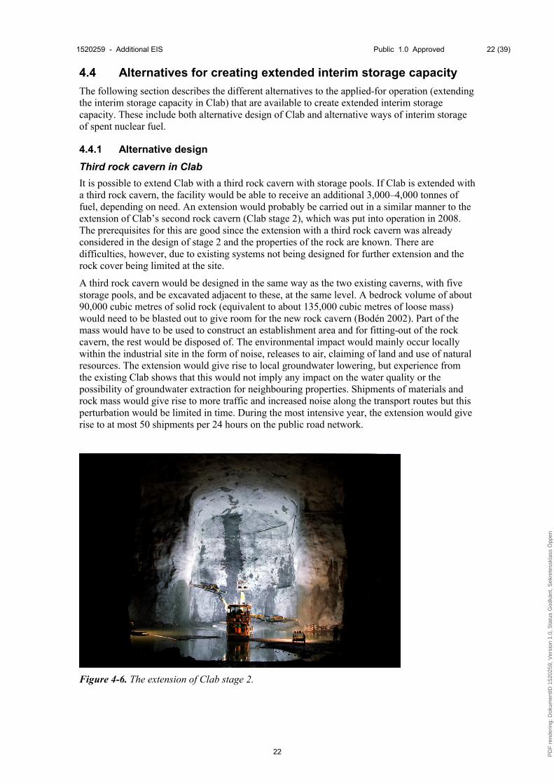
Third rock cavern in Clab
It is possible to extend Clab with a third rock cavern with storage pools. If Clab is extended with a third rock cavern, the facility would be able to receive an additional 3,000–4,000 tonnes of fuel, depending on need. An extension would probably be carried out in a similar manner to the extension of Clab’s second rock cavern (Clab stage 2), which was put into operation in 2008. The prerequisites for this are good since the extension with a third rock cavern was already considered in the design of stage 2 and the properties of the rock are known. There are difficulties, however, due to existing systems not being designed for further extension and the rock cover being limited at the site.
A third rock cavern would be designed in the same way as the two existing caverns, with five storage pools, and be excavated adjacent to these, at the same level. A bedrock volume of about 90,000 cubic metres of solid rock (equivalent to about 135,000 cubic metres of loose mass) would need to be blasted out to give room for the new rock cavern (Bodén 2002). Part of the mass would have to be used to construct an establishment area and for fitting-out of the rock cavern, the rest would be disposed of. The environmental impact would mainly occur locally within the industrial site in the form of noise, releases to air, claiming of land and use of natural resources. The extension would give rise to local groundwater lowering, but experience from the existing Clab shows that this would not imply any impact on the water quality or the possibility of groundwater extraction for neighbouring properties. Shipments of materials and rock mass would give rise to more traffic and increased noise along the transport routes but this perturbation would be limited in time. During the most intensive year, the extension would give rise to at most 50 shipments per 24 hours on the public road network.
Figure 4-6. The extension of Clab stage 2.
PD
F r
ende
ring:
Dok
umen
tID 1
5202
59, V
ersi
on 1
.0, S
tatu
s G
odkä
nt, S
ekre
tess
klas
s Ö
ppen

1520259 - Additional EIS Public 1.0 Approved 23 (39)
23
To protect the existing facility from air shock waves and blasting fumes, temporary separating walls would be established between the excavation and operation area. Excavation work and vibration levels would be regulated and monitored in control programmes. Experience from Clab stage 2 shows that an extension of the facility is possible with maintained safety and without disturbances in the operation of the facility (Söderberg 2007).
The amount of radioactive waste that arises in operation would increase after the extension but not to any large extent. Releases of air and waterborne radioactivity to the environment would be on the same order of magnitude as for the applied-for operation. The number of shipments of spent nuclear fuel to the facility would not differ from the applied-for operation.
To extend Clab with a third rock cavern would require new licences and the lead times for this are significant. An extension may also lead to the need for facility upgrades and constructability analyses that may affect the time consumption. It is therefore uncertain if the new storage space would be available in time before Clab reaches the currently permitted capacity.
4.4.2 Alternative ways to interim-store spent nuclear fuel
Wet interim storage at the nuclear power plants
All nuclear power plants interim-store the spent nuclear fuel in storage pools for some time before it is transported to Clab. Some long-lived waste is also interim-stored in storage pools at the nuclear power plants before it is transported away for interim storage, for example in Clab or in BFA. There is no capacity for interim storage of large amounts of spent nuclear fuel in the pools of the nuclear power plants over a longer time. The existing margins are needed to withstand any disturbances in operations and to provide good prospects for logistics in the pools. Prolonged storage in the storage pools of the nuclear power plants can also make a potential planned decomissioning of one or more reactors more difficult.
New facility for wet interim storage
Since the middle of the 1970s, the focus in Sweden has been to store spent nuclear fuel in a central interim storage facility. To build a completely new facility for wet interim storage is not in line with this strategy as the spent nuclear fuel would be spread out on multiple locations. Building a new facility is still a possible alternative, but would entail a completely new process with a siting study, site investigations, licensing etc. Such a process is time-consuming and the risk is high that there would not be any extended interim storage capacity when Clab reaches the permitted capacity. To construct a new facility also gives rise to larger environmental impact. A new facility for wet interim storage has no obvious advantages compared with other alternatives (for example dry interim storage, which is described below) and is not judged to be a reasonable alternative to increasing the storage capacity in Clab.
Dry interim storage
Dry storage does not presently occur in Sweden and is therefore a new method for SKB and the Swedish regulatory authorities. The method is, however, applied in different designs in several other countries. The main reason for dry interim storage becoming more common in recent years is that the method, compared with wet interim storage, is easier to extend gradually as needs arise and that the operation cost is lower as a rule because cooling can be done through passive inflow of air around the waste packages. However, the fuel temperature is higher for dry storage than for wet storage, which can require stricter limits on burnup and longer decay time before the fuel can be transferred to dry storage. Normally fuel is stored wet for 5–10 years before it can be moved to dry storage.
For dry interim storage the fuel is dry, surrounded by inert gas, inside tight containers that are cooled by the surrounding circulating air. The requirement on radiation shielding can either be met by the thickness of the material in the containers, or if these are too thin (so-called canisters), by in turn placing them inside sufficiently thick outer containers, or concrete modules, see Figure 4-7. The basic requirements on safety and physical protection for dry storage are the same as for wet interim storage of spent nuclear fuel. Foreign experience on an
PD
F r
ende
ring:
Dok
umen
tID 1
5202
59, V
ersi
on 1
.0, S
tatu
s G
odkä
nt, S
ekre
tess
klas
s Ö
ppen

1520259 - Additional EIS Public 1.0 Approved 24 (39)
24
industrial scale shows that dry storage facilities can be established and operated in a way that fulfils these requirements. It is only regarding retrieval of fuel from a container after a longer period of storage that the practical experience is limited. The same applies to the data concerning the fuel’s potentially altered properties after dry storage for a long time.
A dry storage facility could in principle be placed anywhere in Sweden. A reasonable siting is in the vicinity of Clab. That is where most of the spent fuel from the operation of the Swedish reactors is found today and where new spent fuel will be transported. Furthermore, Clab is a centre of competence for the handling of spent fuel with many functions that could also be used for construction and operation of a dry storage facility.
Figure 4-7. Castor container for dry interim storage in a storage building at Gorleben in Germany. The container also fulfils the requirement of being transportable.
There are two possible strategies for emplacement of spent nuclear fuel in a dry storage facility at Clab. One variant is that the fuel already in Clab remains there while additional fuel from the nuclear power plants arrives in transportable and dry-storable waste containers that are put in a storage building in the vicinity of Clab. The containers can be loaded with spent nuclear fuel only after three years of decay in the fuel pools at the nuclear power plants. When the containers have been loaded with nuclear fuel, they are drained and dried before they are transported to the dry storage facility in Clab. Another variant is that old fuel is removed from Clab for dry storage, whereby room is made in Clab for the fuel continuously supplied from the nuclearpower plants. For this procedure, the fuel from the storage pools in Clab is moved to the handling pools where the fuel is loaded in containers for dry storage.
Loading of dry storage containers at the nuclear power plants assumes that there is room for fuel corresponding to three years of production at the nuclear power plants, which is currently not the case for all plants. Creating new wet storage capacity at the nuclear power plants is, on the other hand, not deemed possible. Otherwise, the main differences between the two strategies are the number of transloadings and the size and cost of dry storage containers. With old fuel, more fuel assemblies can be loaded in each container since the specific heat generation and the radiation from the fuel assemblies are lower.
All handling of the spent nuclear fuel would occur shielded from radiation with controlled ventilation. Release of radioactivity would only occur to the water in the pools during loading and to the air during drying and other handling. The radioactivity would be carried away by the cleanup and ventilation systems to finally gather on air filters and in ion exchangers. The initial handling at the nuclear power plants and Clab would thereby give rise to limited releases of radioactivity to both air and water. The releases would be decontaminated as needed and
PD
F r
ende
ring:
Dok
umen
tID 1
5202
59, V
ersi
on 1
.0, S
tatu
s G
odkä
nt, S
ekre
tess
klas
s Ö
ppen

1520259 - Additional EIS Public 1.0 Approved 25 (39)
25
measured continuously. The containers used for dry interim storage are tight and thereby no release of activity would occur in the dry storage facility itself.
Dry storage of the spent nuclear fuel would give rise to both operational and decommissioning waste. Since the handling of the fuel is similar to today, the operational waste that a dry storage facility gives rise to would be of the same kind as the corresponding operational waste from e.g. Clab Appendix K:23, Radiological consequences (SKBdoc 1467351) (in Swedish).
In the construction of a dry storage facility the environmental impact would mainly occur locally in the form of noise, releases to air and claiming of land. Shipments of materials would give rise to more traffic and noise along the transport routes but this perturbation would be limited in time.
The introduction of a dry interim storage in the Swedish system would be a time-consuming process. In view of the fact that it is a new nuclear facility with a new technology for Sweden, it is likely to take at least ten years before a dry storage facility can be ready for operation. This means that the possibility to achieve a dry storage facility before Clab reaches the permitted capacity is very small. Dry storage is thus not a feasible alternative to the selected alternative of extended capacity in Clab (SKBdoc 1469424) (in Swedish).
4.4.3 Summarizing assessment
SKB has studied advantages and disadvantages of different alternatives for interim storage of the spent nuclear fuel that exceeds Clab’s existing license. In a comparison of alternatives, SKB has deemed the most suitable alternative to be utilizing the existing facility more efficiently. In this way the environmental consequences are minimized since neither new land nor new natural resources need to be utilised. It is also the solution that takes least time to carry out, which means that the extended interim storage capacity is ensured in good time before Clab reaches its currently permitted capacity.
Extending Clab with a third rock cavern or building a new facility for dry interim storage are alternatives that are fully feasible from both a technical, environmental and safety-related point of view. The lead times are, however, considerable, and these solutions are therefore not realistic alternatives to the applied-for option. If the KBS-3 system should be greatly delayed, on the other hand, one of these alternatives could be considered for meeting the need for further storage capacity after year 2036.
PD
F r
ende
ring:
Dok
umen
tID 1
5202
59, V
ersi
on 1
.0, S
tatu
s G
odkä
nt, S
ekre
tess
klas
s Ö
ppen

1520259 - Additional EIS Public 1.0 Approved 26 (39)
26
5 Clink – Integrated Facility for Interim Storage and Encapsulation
A description of the Clink facility (Integrated Facility for Interim Storage and Encapsulation) can be found in Appendix TB – Technical description (in Swedish), and in the revised technical description – Appendix K:24 (in Swedish), and a description of the operations and subsequent consequences is given in Chapter 9 in the EIS submitted in 2011. The present Chapter describes changes in the applied-for facility design and operations in Clink deemed to be of importance for previously described consequences. Furthermore, the changes in consequences that these changes in operations give rise to and how this affects the consequences of the entire applied-for activity is described.
5.1 Main changes in facility and operations due to stricter safety requirements
The planned changes in the facility and the activities applied for are described in the revised technical description (Appendix K:24, in Swedish) and summarised below.
5.1.1 The facility and common systems
The changes in the cooling and cleanup systems, which are described for Clab in Section 4.1, also apply for the integrated Clink facility.
In addition to these improvements, the design of Clink has changed both above and below ground compared to what was described in the application submitted in 2011. In order to be better protected against e.g. earthquakes and aeroplane crashes, the buildings will have thicker concrete walls and a more “bunker-like” appearance compared to what was previously described, see Figure 5-1. A water tank will also be constructed within the area as a part of a passive safety system that will ensure water supply to the pools and work independently of power supply by means of only gravity. The fence will be moved about 40 metres to the west, so that the facilities needed for the planned construction organization will fit inside, see Figure 5-2. This is for safety reasons, so that the physical protection of the facility is not affected.
Figure 5-1. Photo montage showing planned design of Clink.
PD
F r
ende
ring:
Dok
umen
tID 1
5202
59, V
ersi
on 1
.0, S
tatu
s G
odkä
nt, S
ekre
tess
klas
s Ö
ppen

1520259 - Additional EIS Public 1.0 Approved 27 (39)
27
Figure 5-2. Disposition of buildings within the operations area for Clink. The changes mainly consist of moving the fence about 40 metres to the west, an additional water tower and altered design of buildings.
Underground, new horizontal tunnels and vertical cooling shafts are constructed to permit a new independent air cooling system, see Figure 5-3. The air cooling system will constitute a backup system to cool the facility in the event that the system for water cooling does not function as intended and will thus increase the facility’s redundancy.
Figure 5-3. Additional cooling shafts and tunnels for the new air cooling system have been marked with green colour.
PD
F r
ende
ring:
Dok
umen
tID 1
5202
59, V
ersi
on 1
.0, S
tatu
s G
odkä
nt, S
ekre
tess
klas
s Ö
ppen

1520259 - Additional EIS Public 1.0 Approved 28 (39)
28
Three new diesel generators (an additional effect of about 2.5 MW) will be placed in different locations within the facility to permit power supply in the event of a network loss. One or more oil tanks which together hold about 100 cubic metres of diesel will be built within the area to provide the backup generators with fuel. To meet the need of concrete, a concrete mixing station will be built in the vicinity of Clab/Clink.
5.1.2 The operations
Handling of rock mass
Planned changes in Clink (see Section 5.1.1) imply an additional ~15,000 cubic metres of solid rock excavated from new cooling shafts and tunnels (~12,000 cubic metres of rock) as well as extension of the establishment area (~3,000 cubic metres of rock). Together with the previously specified rock volumes of 24,000 cubic metres that arise in connection with excavating of a pool in Clink and other ground work, the quantity of solid rock is judged to amount to a total of 39,000 cubic metres (105,000 tonnes).
A mass balance calculation has been made for Clink (SKBdoc 1469193, in Swedish) where the need for rock mass in the project was estimated to the following:
- The need for aggregate is about 132,000 tonnes.
- The need for backfill is about 122,000 tonnes
In total the project is thus calculated to have a deficit of rock mass of about 150,000 tonnes.
Since excavated rock mass is needed in the project, SKB at present plans to use the nearby located rock heap Bockstrupen (see Figure 5-4) for storage and handling of rock mass prior to reuse. Bockstrupen is operated by OKG.
Figure 5-4. The rock heap Bockstrupen is situated about one kilometre northeast of Clink.
PD
F r
ende
ring:
Dok
umen
tID 1
5202
59, V
ersi
on 1
.0, S
tatu
s G
odkä
nt, S
ekre
tess
klas
s Ö
ppen

1520259 - Additional EIS Public 1.0 Approved 29 (39)
29
Extended interim storage
Even when Clab is integrated with the encapsulation plant and becomes Clink, interim storage of 11,000 tonnes of spent nuclear fuel is planned as well as handling, including possible segmentation of core components, see Section 4.2.1.
5.1.3 Resulting operations
Increased excavation of rock mass and increased need for concrete and reinforcement imply an increase in the number of truck transports to and from the area. The difference in passenger car transports is marginal.
In the previous transport study that served as a basis for the original EIS, it was assumed that all concrete and rock mass needed to be transported between Oskarshamn and Clink. This assumption is no longer eligible, since it is judged possible to a large extent to transport between Clink and the rock heap Bockstrupen. The original EIS indicated that the construction of Clink gives rise to a total of 170 vehicle passages per 24 hours, of which 90 consist of heavy transport and 80 of passenger car transport. All were judged to leave the industrial site and burden the public road network, see Section 9.1.2.1 in the original EIS.
The current assessment is that the construction of Clink gives rise to a total of 280 vehicle movements per 24 hours, of which 200 consist of heavy transport and 80 of passenger car transport. If Bockstrupen is used, the large difference from previous calculations is that the transport of rock mass will only occur within the industrial site to or from Bockstrupen (a distance of about one kilometre). The public road network is then burdened by 125 vehicles movements per 24 hours, of which 45 consist of heavy transport and 80 of passenger car transport. In conclusion, the increased excavation implies more heavy transport within the industrial site while the contribution to heavy transport in the public road network with current planning is judged to be reduced to half compared with previous assessments (SKBdoc 1469193, in Swedish).
5.2 Impact, effects and consequences
5.2.1 Radiation and release of radiological substances and their consequences
This section is an addition to Sections 9.1.3.4, 9.1.4.1 and 9.1.5.2 in the original EIS. Descriptions, calculations and assessments in this section are mainly taken from Appendix K:23, Radiological consequences (SKBdoc 1467351) (in Swedish). The section presents combined consequences for interim storage and encapsulation of spent nuclear fuel.
The extended interim storage in Clink entails that there will be more spent nuclear fuel in the facility than predicted by previous calculations of radioactivity release to air and water and dose to the personnel and critical group. This justifies that these calculations are consequently updated with regard to interim storage of 11,000 tonnes of spent nuclear fuel and the changes or additional processes this entails.
Radioactivity release in the facility in normal operation
In conjunction with reception, handling and encapsulation of spent fuel, as well as during the general operation of the facility, radioactivity is released that can then expose the personnel working in the facility to dose or give rise to releases to the environment.
Extended interim storage and the additional handling steps and work operations it implies concern both Clab and Clink. Processing of core components in the form of segmentation of control rods may be considered in both Clab and Clink and this additional operation will be the same regardless of whether it takes place in Clab or Clink. The same applies for transloading of fuel to compact storage canisters. For specific assessments of the contributions to release and dose caused by transloading and segmentation, see Section 4.3.1.
PD
F r
ende
ring:
Dok
umen
tID 1
5202
59, V
ersi
on 1
.0, S
tatu
s G
odkä
nt, S
ekre
tess
klas
s Ö
ppen

1520259 - Additional EIS Public 1.0 Approved 30 (39)
30
Changes in the facility and operations due to stricter safety requirements do not affect the work operations leading to radioactivity release in the facility. Figure 5-5 illustrates the fuel’s path through Clink together with the handling steps and work operations that are of importance for radioactivity release. When the fuel is taken from the interim storage pools prior to encapsulation, it is above all the transloading to transport storage canisters and drying of fuel that affect the radioactivity release.
Figure 5-5. The fuel’s path through Clink and main processes that can give rise to radioactivity release.
Release of radioactivity to air and water at normal operation
Calculations of releases of radioactivity to air and water recipients for interim storage of 11,000 tonnes of spent fuel and encapsulation of about 400 tonnes per year are presented in Table 5-1. Release calculations are reported for a so-called realistic case. In order to give a reasonable upper limit for the releases that can be expected from the operations and also be prepared for minor changes of the operation of the facility there is, however, some conservatism in the realistically calculated releases. The calculations for example assume a reception of 300 tonnes of spent fuel per year compared with the average actual reception of about 200 tonnes per year.
PD
F r
ende
ring:
Dok
umen
tID 1
5202
59, V
ersi
on 1
.0, S
tatu
s G
odkä
nt, S
ekre
tess
klas
s Ö
ppen
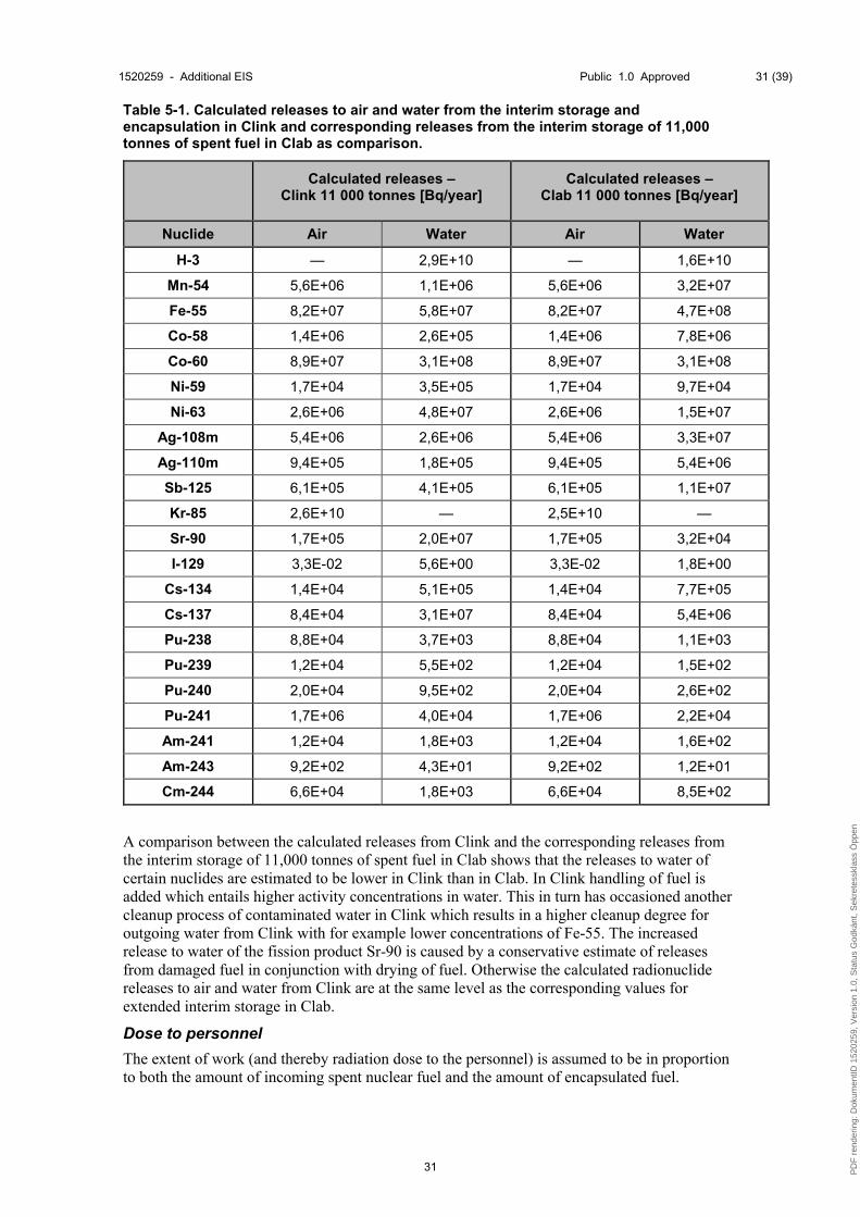
1520259 - Additional EIS Public 1.0 Approved 31 (39)
31
Table 5-1. Calculated releases to air and water from the interim storage and encapsulation in Clink and corresponding releases from the interim storage of 11,000 tonnes of spent fuel in Clab as comparison.
Calculated releases –Clink 11 000 tonnes [Bq/year]
Calculated releases –Clab 11 000 tonnes [Bq/year]
Nuclide Air Water Air Water
H-3 — 2,9E+10 — 1,6E+10
Mn-54 5,6E+06 1,1E+06 5,6E+06 3,2E+07
Fe-55 8,2E+07 5,8E+07 8,2E+07 4,7E+08
Co-58 1,4E+06 2,6E+05 1,4E+06 7,8E+06
Co-60 8,9E+07 3,1E+08 8,9E+07 3,1E+08
Ni-59 1,7E+04 3,5E+05 1,7E+04 9,7E+04
Ni-63 2,6E+06 4,8E+07 2,6E+06 1,5E+07
Ag-108m 5,4E+06 2,6E+06 5,4E+06 3,3E+07
Ag-110m 9,4E+05 1,8E+05 9,4E+05 5,4E+06
Sb-125 6,1E+05 4,1E+05 6,1E+05 1,1E+07
Kr-85 2,6E+10 — 2,5E+10 —
Sr-90 1,7E+05 2,0E+07 1,7E+05 3,2E+04
I-129 3,3E-02 5,6E+00 3,3E-02 1,8E+00
Cs-134 1,4E+04 5,1E+05 1,4E+04 7,7E+05
Cs-137 8,4E+04 3,1E+07 8,4E+04 5,4E+06
Pu-238 8,8E+04 3,7E+03 8,8E+04 1,1E+03
Pu-239 1,2E+04 5,5E+02 1,2E+04 1,5E+02
Pu-240 2,0E+04 9,5E+02 2,0E+04 2,6E+02
Pu-241 1,7E+06 4,0E+04 1,7E+06 2,2E+04
Am-241 1,2E+04 1,8E+03 1,2E+04 1,6E+02
Am-243 9,2E+02 4,3E+01 9,2E+02 1,2E+01
Cm-244 6,6E+04 1,8E+03 6,6E+04 8,5E+02
A comparison between the calculated releases from Clink and the corresponding releases from the interim storage of 11,000 tonnes of spent fuel in Clab shows that the releases to water of certain nuclides are estimated to be lower in Clink than in Clab. In Clink handling of fuel is added which entails higher activity concentrations in water. This in turn has occasioned another cleanup process of contaminated water in Clink which results in a higher cleanup degree for outgoing water from Clink with for example lower concentrations of Fe-55. The increased release to water of the fission product Sr-90 is caused by a conservative estimate of releases from damaged fuel in conjunction with drying of fuel. Otherwise the calculated radionuclide releases to air and water from Clink are at the same level as the corresponding values for extended interim storage in Clab.
Dose to personnel
The extent of work (and thereby radiation dose to the personnel) is assumed to be in proportion to both the amount of incoming spent nuclear fuel and the amount of encapsulated fuel.
PD
F r
ende
ring:
Dok
umen
tID 1
5202
59, V
ersi
on 1
.0, S
tatu
s G
odkä
nt, S
ekre
tess
klas
s Ö
ppen

1520259 - Additional EIS Public 1.0 Approved 32 (39)
32
The prognosis of the summed collective dose for interim storage and encapsulation in Clink is estimated all in all to about 97 mmanSv per year, compared with today’s experience value in Clab of about 32 mmanSv. This difference is to some extent due to the difference in computational methods, where for Clink it has been assumed that the reception capacity is 300 tonnes of fuel per year while the experience values in Clab are based on 200 tonnes of incoming fuel per year. In addition, there are new work operations whose contribution to dose has been estimated based on experience from similar work in Clab.
Dose to the critical group
Releases and dose to the critical group from reception and interim storage of spent fuel in Clab are very low and the corresponding doses for Clink are also calculated to be low. The dose to the critical group is on the order of 10-5 mSv per year, see Table 5-2. For nuclear facilities, there are requirements that the combined dose to the critical group from facilities within the same geographic area may not exceed 0.1 mSv per year. Releases and dose essentially stem from reception and other handling of the spent fuel. An increase of the interim-stored amount of spent fuel to 11,000 tonnes will only lead to marginal increases in releases. Worth noting is that the calculated doses to the critical group from controlled releases to water from Clink are lower than in Clab 11,000 tonnes. This is in line with the release calculations presented in Table 5-1 with lower releases to water of certain nuclides due to a more efficient cleanup strategy for contaminated water in Clink.
Table 5-2. Calculated annual doses to the critical group for releases from Clink based on realistic assumptions.
Annual doses to the critical group [mSv]
Adults 0-1 years 1-2 years 2-7 years 7-12 years 12-17 years
Air 1,0E-05 8,5E-06 1,1E-05 1,1E-05 1,2E-05 1,2E-05
Water 5,0E-07 5,2E-09 1,4E-06 1,2E-06 1,2E-06 1,1E-06
Total 1,1E-05 8,5E-06 1,2E-05 1,2E-05 1,3E-05 1,3E-05
Natural environment
Since the radioactivity releases to the environment due to the extended interim storage are judged to be marginal, the previous conservative assessments in Section 9.1.4.1 in the original EIS regarding consequences for the natural environment remain. Radiological releases during normal operation are not judged to give rise to any consequences for the animals and plants in the area.
5.2.2 Consequences of disturbances and mishaps
In order to fulfil the coming nuclear safety requirements, the revised facility design of Clink includes several larger safety-enhancing changes, compared with the design presented in the application 2011.
The facility has three safety functions with the task of protecting barriers: prevent criticality, decay power cooling and containment of radioactive substances. The safety function prevent criticality ensures that the fuel is subcritical also in the case of improbable events. The safety system for decay power cooling uses air as a heat sink and is initiated for events which cause a loss of the normal operation cooling. The safety system for decay power cooling is supplied by power from a diesel-backed network. As a diversification to the safety system for decay power cooling, there is a passive feed system for make-up water, using the force of gravity.
In all processing steps where spent nuclear fuel is handled there are at least three barriers as protection against dispersion of radioactivity in the environment. The safety function
PD
F r
ende
ring:
Dok
umen
tID 1
5202
59, V
ersi
on 1
.0, S
tatu
s G
odkä
nt, S
ekre
tess
klas
s Ö
ppen

1520259 - Additional EIS Public 1.0 Approved 33 (39)
33
containment of radioactive substances protects the third barrier during the dry handling in the encapsulation plant. The third barrier in that case consists of walls, floor and roof in the handling cell and the function is maintained with the aid of ventilation systems for controlled vaults.
In addition, there is a backup control room from which all safety functions can be controlled and monitored as well as a secure power supply with the aid of both diesel generators and batteries. The revised design also means extended earthquake security measures for buildings and systems, and that buildings will have better protection against e.g. an aeroplane crash.
The completed criticality analysis shows that the spent nuclear fuel can be stored with sufficient margin to criticality in Clink, taking into account uncertainty factors.
The design cases regarding dose to personnel are a dropped fuel assembly in the unloading pool in the interim storage part and a dropped storage canister in the encapsulation plant. A dropped storage canister in the encapsulation plant gives the highest contribution to dose and amounts to 0.44 mSv of the total effective dose to the personnel and 41 mSv regarding dose to the eye lens and skin. Since the acceptance criteria are 50 mSv and 150 mSv per year, all calculated doses with good margin fulfil the established acceptance criteria.
The acceptance criteria for radiological environmental impact has been tightened in relation to the existing criteria for Clab. The highest effective dose to the critical group is calculated to be less than 0.006 mSv for the design event when a transport storage canister is dropped in a handling cell in Clink. Thus, the reported calculations for improbable events show that the acceptance criterion of 20 mSv is met for all cases with very good margin.
Clink has been constructed so that the dose to the critical group should not exceed the reference values given in SSM’s newly announced requirements. Clink will thereby have very high resilience to disturbances and mishaps, which means that not even improbable events will lead to unacceptable releases.
5.2.3 Radioactive operational waste
Quantities and properties of the operational waste generated in Clink are unaltered compared with the data presented in the original EIS from 2011, except for the operational waste that extended interim storage can give rise to. The additional operational waste from extended interim storage is presented in Section 4.3.3. Detailed information on the summed radioactive operational waste generated by Clink is presented in Appendix K:23, Radiological consequences (SKBdoc 1467351) (in Swedish).
5.2.4 Claiming of ground and its consequences
The existing operations area for Clab is planned to be broadened about 90 metres to the west, which is an increase of 40 metres compared with what is specified in the original EIS from 2011. This means that an additional 7,400 square metres is put into use and sealed in a similar manner to that described under 9.1.3.1 in the original EIS. Surface water within the broadened establishment area will be handled in the way described earlier in Section 9.1.3.7 in the original EIS. The outcrop pine forest that is utilised lacks high natural values. Even if a slightly larger part of the forest area is claimed, the impact is assessed, in the same way as in Section 9.1.4.1 in the original EIS, to imply insignificant consequences for the natural environment.
5.2.5 Impact on groundwater level
The previously planned rock shaft described in the original EIS for Clink is expected to increase the in-leakage of groundwater with up to about ten percent compared with the operation of Clab 1 and Clab 2 (Werner 2010). This in-leakage is based on calculations as well as experience from construction and operation of Clab 1 and 2.
The cooling shafts and tunnels that are introduced in the planned new design of Clink’s underground parts (see Section 5.1.1) will be built adjacent to and at the same level as the
PD
F r
ende
ring:
Dok
umen
tID 1
5202
59, V
ersi
on 1
.0, S
tatu
s G
odkä
nt, S
ekre
tess
klas
s Ö
ppen

1520259 - Additional EIS Public 1.0 Approved 34 (39)
34
existing underground parts of the facility, which limits their impact. The rock shaft, in combination with additional cooling shafts and tunnels, is expected to increase the in-leakage of groundwater by up to about 20 percent compared with the operation of Clab 1 and Clab 2. The limited increase of in-leakage gives the same conclusion as in (Werner 2010), i.e. that the construction of the encapsulation plant and operation of the integrated Clink facility will only lead to small and local effects on groundwater levels in the rock. The diversion point for in-leaking groundwater does not change due to added cooling shafts. For a closer description and assessment of groundwater impact see Appendix K:22, Diversion of groundwater in conjunction with the construction of Clink (SKBdoc 1466604) (in Swedish).
5.2.6 Noise and vibrations and their consequences
Noise
Planned changes in Clink and an altered execution planning is judged to give rise to less transport on the public road network than described in the original EIS. For assessment of transports see Section 5.1.3. The impact of noise from Clink during the construction phase is thus judged to decrease slightly compared with previous descriptions in the original EIS, Section 9.1.4.4. The number of events with maximal noise levels in residential buildings becomes less with the current planning.
A potential concrete mixing station adjacent to Clab/Clink does not alter previous descriptions and assessments of the impact of noise from the operations since crushing of rock has already been included in previous analyses, see Section 9.1.3.3 in the original EIS.
Vibrations
Blasting of rock for the new cooling shafts and tunnels gives rise to vibrations and air shock waves, i.e. a pressure change in the air that arises in conjunction with rock blasting. Planning and execution of rock work will be controlled by the caution required by the vicinity to Clab’s rock cavern. Experience from construction of Clab 2 shows that blasting can be carried out without affecting the stability or function of the existing storage. The constructability analysis for Clink will be updated so that additional shafts and tunnels are also taken into consideration when choosing a method for blasting and adopting safety measures.
5.2.7 Non-radiological releases to air and its consequences
Additional blasting and transport of building materials and rock mass, see Section 5.1, will contribute to the release of additional air pollution. Also the testing of the three new backup generators about once a month will contribute to atmospheric emissions. Shipments of rock mass, which are the largest part of the shipments, are planned to occur only for short distances locally which limits the impact. A potential concrete mixing station in the area can contribute to some dusting which can be bounded by water spraying. Additional transports and other activities are not judged to be of such an extent that they entail a change of the assessments that were made in the original EIS in Section 9.1.4.4, Releases of other elements to air. In this context it can be mentioned that analyses of releases to air have been carried out previously for the construction of a final repository for spent nuclear fuel in the area. Not even this more extensive facility and transport operation was judged to imply any significant impact (Fridell et al. 2008). Additional atmospheric emissions do not thus imply any risk for exceeding the environmental quality standards for air and are not judged to cause any impact on the health of the local population.
5.2.8 Non-radiological release to water and its consequences
The planned changes in Clink (see Section 5.1.1 and 5.1.2) would entail blasting of 12,000 cubic metres of rock underground for construction of cooling shafts and new tunnels and 3,000 cubic metres above ground for increasing the establishment area. The total amount of rock blasted is calculated to be 39,000 cubic metres, of which 24,000 consists of the rock volumes that arise in connection with blasting above ground for excavating of a pool in Clink and ground
PD
F r
ende
ring:
Dok
umen
tID 1
5202
59, V
ersi
on 1
.0, S
tatu
s G
odkä
nt, S
ekre
tess
klas
s Ö
ppen
1520259 - Additional EIS Public 1.0 Approved 35 (39)
35
work, as described earlier in (SKBdoc 1386598) (in Swedish). Nitrogen releases in conjunction with blasting are generally larger if blasting is done underground than if it takes place above ground since the amount of explosives used is higher per cubic metre of rock and the loss of explosives is higher in conjunction with this type of blasting.
Additional blasting underground entails that the nitrogen releases caused by construction of Clink increase greatly compared with previous calculations (from just below 80 kilograms to more than 600 kilograms). The amounts of nitrogen released in the drainage water, however, are considered to be small in relation to the recipient’s water exchange and the consequences of the nitrogen releases are judged to be negligible in relation to the size and resilience of the recipient. Assuming that the nitrogen release of approximately 600 kilograms occurs during the same year, it would lead to a mean concentration contribution of approximately 0.07 µg/L for complete and conservative mixing. This is very low compared to the mean concentration of dissolved inorganic nitrogen in coastal water from this region, which was 23 µg/L during the period 2002–2006. The very marginal and temporary load from drainage water will not affect the nitrogen flow in the water, and thereby does not affect the possibility of achieving good ecological status in 2021 or good chemical status in 2015. For a closer description and assessment of the impact on the aquatic environment, see Appendix K:25, Impact on aquatic environments in conjunction with the construction and operation of Clink (SKBdoc 1469340) (in Swedish).
5.2.9 Environmental risks
Additional diesel generators for backup power and associated fuel handling, diesel tank etc., entail a risk in the form of release to the ground in the case of a potential accident. This type of accident has in the previously completed risk analysis been judged to imply relatively small consequences if it occurs (Magnusson 2009) and this judgement remains. As described in the original EIS in Section 9.1.5.1, the risk is minimized by e.g. bunding of tanks, good organization and preparation for decontamination of potential releases.
The changes that are being carried out in Clink to increase the facility’s safety, additional water tower etc. are generally judged as positive also from the standpoint of environmental risk, since they provide larger redundancy and an opportunity to prevent and limit accidents like fires.
PD
F r
ende
ring:
Dok
umen
tID 1
5202
59, V
ersi
on 1
.0, S
tatu
s G
odkä
nt, S
ekre
tess
klas
s Ö
ppen

1520259 - Additional EIS Public 1.0 Approved 36 (39)
36
6 Zero alternative The present Chapter replaces parts of Chapter 11 in the EIS submitted in 2011. The sections that remain unaltered are 11.1.2 Risk and safety matters and 11.2 Site development. These sections are therefore not reproduced here.
The zero alternative aims to describe a likely development if the applied-for activity is not realized. This does not mean that everything remains unchanged, and the zero alternative may therefore differ from the situation today. This means that both the existing operations and the selected site may be developed within the time perspective that is being studied. There is, however, no room within the zero alternative for describing other ways to achieve the same purpose of the operations. Dry interim storage in Clab or extension of Clab with a third rock cavern is not part of the zero alternative. These scenarios are handled instead within the framework of the account of alternatives to the planned operations (see Section 4.4). The zero alternative thus only encompasses continued storage in Clab.
6.1 Continued interim storage of at most 8,000 tonnes of spent nuclear fuel in Clab
The zero alternative entails that storing of spent nuclear fuel and core components continues as before until the storage amount in the current licence of 8,000 tonnes of spent nuclear fuel is reached. This will according to today’s forecasts occur around 2023. This means that Clab can not receive spent nuclear fuel after 2023 and that interim storage of the remaining amount of spent nuclear fuel must be solved in another way. In the short term, there is a possibility of utilizing the maximum interim storage capacity in the storage pools at the nuclear power plants. There is, however, no capacity for interim storage of a larger amount of spent nuclear fuel in the pools of the nuclear power plants for a longer time. Prolonged storage in the storage pools of the nuclear power plants can also make a potential planned decomissioning of one or more reactors more difficult. In the longer term the zero alternative entails that the existing system for waste management will not provide sufficient room for interim storage of the spent nuclear fuel generated by the electricity production at the nuclear power plants after the year 2023. Nor is it possible to in 2023 arrange interim storage capacity on another site. Thereby, it would ultimately have consequences for the nuclear power plant’s capacity to produce electricity.
If a licence is given for storing 11,000 tonnes in Clab, but not for the KBS-3 system as a whole, this would mean that storing in Clab can continue until around year 2036.
The zero alternative also means that the spent nuclear fuel needs to be stored for a longer time in Clab. Such a prolonged storage is expected to, as long as it takes place under controlled forms, provide an impact corresponding to the operation of the existing Clab. There are, however, a couple of prerequisites that change for prolonged storage: firstly, changes may occur in the surrounding environment, e.g. by the Oskarshamn nuclear power plant being decommissioned; secondly, the radioactivity and heat output of the spent nuclear fuel will decrease with time. That the radioactivity of the nuclear fuel decays with time means that the amount of radioactive substances released to the facility’s cleanup systems for air and water, and, to some extent, to the environment, decreases with time for prolonged operation of Clab. Clab is today supported with water from the Oskarhamn plant’s water treatment plant and sewage water is purified in the Oskarshamn plant’s sewage treatment plant. When the reactors are shut down, alternative solutions for water supply and treatment of sewage water may be needed since Clab provides only a small part of the water today coming from water treatment plants and to sewage treatment plants. After shutdown of the reactors, Clab alone will be responsible for the releases of cooling water to Hamnefjärden. The overall temperature impact on Hamnefjärden will then be significantly reduced. The heat output via Clab’s cooling water will also be reduced progressively by the fuel’s decay power decreasing with time.
PD
F r
ende
ring:
Dok
umen
tID 1
5202
59, V
ersi
on 1
.0, S
tatu
s G
odkä
nt, S
ekre
tess
klas
s Ö
ppen

1520259 - Additional EIS Public 1.0 Approved 37 (39)
37
7 Overall assessmentAn increased amount of spent nuclear fuel interim-stored in Clab entails relatively small consequences since it in practice means that the existing systems can be used more efficiently. Using the existing facilities for interim storage of additional amounts of spent nuclear fuel implies good management of available resources.
An increase of the interim-stored amount of spent fuel to 11,000 tonnes will only lead to marginal increases of releases and dose, since spent fuel will be received at approximately the same rate as before. Transloading of spent fuel to compact storage canisters is judged not to give rise to releases of radioactivity to the environment, while handling of core components (mainly segmentation of control rods) is calculated to give rise to limited releases of radioactivity. All in all, the releases of radioactivity to air and water for extended interim storage and encapsulation of the spent nuclear fuel are calculated to be far below the current requirements of 0.1 mSv.
An increase in the amount of stored fuel entails that the decay power in the storage pools increases. This leads to a faster sequence of events regarding increasing pool temperature and decreasing water level in the case of a loss of cooling water flow. The probability for fuel exposure, however, is considered to be negligible, even for extended interim storage of 11,000 tonnes of nuclear fuel. The changes in the Clink facility design entail increased safety for the facility, which is positive for both humans and the environment.
The impact of the changes due to increased rock excavation, claiming of land etc, is limited and the consequences are small and local. Previous descriptions of consequences for Clab and Clink in the original EIS are not judged to be affected to any significant extent and thereby neither are the consequences for the KBS-3 system as a whole.
PD
F r
ende
ring:
Dok
umen
tID 1
5202
59, V
ersi
on 1
.0, S
tatu
s G
odkä
nt, S
ekre
tess
klas
s Ö
ppen

1520259 - Additional EIS Public 1.0 Approved 38 (39)
38
8 ConsultationsThe EIS for the KBS-3 system submitted in 2011 describes completed consultations up to submission of the applications in 2011. Since then, SKB has conducted further consultations from November to December 2014 that also included a general consultation meeting in the Oskarshamn Municipality. These consultations focused on the question of increased capacity for interim storage of spent nuclear fuel in Clab from the 8,000 tonnes permitted today (counted as uranium) to 11,000 tonnes.
A description of the implementation of consultations, consultation material, minutes from the consultation meeting, feedback received and SKB’s response etc. are found in Appendix K:21, Addition to the account of consultations (in Swedish).
8.1 Feedback received and SKB’s response
The questions asked in the consultation meeting were mainly about SKB’s plans for the core components that need to be transported from Clab to make room for 11,000 tonnes of fuel and about the prerequisites for dry storage of fuel as an alternative to closer packing in Clab’s pools. Furthermore, the safety of the existing interim storage facility in the event of different types of incidents, disturbances and events was discussed as well as what the account of the zero alternative should contain.
The written feedback received essentially treated the same issues as the questions asked in the meeting. Furthermore, feedback was received on what should be included in the application and how the supplementary EIS should be disposed to make it clear and easy for the reader to see what has changed. SKB has taken this feedback into account in the design of this additional EIS and associated appendices.
PD
F r
ende
ring:
Dok
umen
tID 1
5202
59, V
ersi
on 1
.0, S
tatu
s G
odkä
nt, S
ekre
tess
klas
s Ö
ppen

1520259 - Additional EIS Public 1.0 Approved 39 (39)
39
References SKB’s publications can be found at www.skb.se/publications. Unpublished documents will be submitted upon request to [email protected].
The references are only available in Swedish.
Bodén A, 2002. CLAB etapp 2. Bergarbeten. Slutdokumentation. SKB TP-01-03. Svensk Kärnbränslehantering AB
Fridell E, Haeger-Eugensson M, Jöborn I, Peterson K, Svensson A,Forsberg B, 2008. Miljö- och hälsokonsekvenser av utsläpp till luft. Slutförvar Oskarshamn (inklusive Clab och inkapslingsanläggning). SKB P-08-67, Svensk Kärnbränslehantering AB.
Magnusson M, Pettersson L, Oritsland A, 2009. Miljöriskanalys för Clab, inkapslingsanläggning och slutförvarsanläggning. SKB P-09-78, Svensk Kärnbränslehantering AB.
Söderberg L, 2007. CLAB etapp 2. Slutrapport med erfarenhetsåterföring. SKB TP-05-03. Svensk Kärnbränslehantering AB
Werner K, 2010. Vattenverksamhet i Laxemar-Simpevarp: Clab/inkapslingsanläggning (Clink) – bortledande av grundvatten, uttag av kylvatten från havet samt anläggande av dagvattendamm. SKB R-10-20, Svensk Kärnbränslehantering AB.
Unpublished documents
SKBdoc id, version Titel Issuer, year
1386598, ver 1.0 Konsekvensbedömning för vattenmiljöer – Mellanlagring, inkapsling och slutförvaring av använt kärnbränsle. Bilaga K:5.
SKB, 2013
1460199, ver 1.0 Samrådsredogörelse. Bilaga K:21. Samråd enligt miljöbalkens 6:e kapitel 4 § avseende tillstånd till utökad kapacitet för mellanlagring.
SKB, 2015
1466604, ver 1.0 Bortledande av grundvatten i samband med uppförande av Clink. Bilaga K:22. Tillägg till Vattenverksamhet Laxemar-Simpevarp, SKB R-10-20 (bilaga till ursprunglig MKB).
SKB, 2015
1467351, ver 1.0 Radiologiska konsekvenser i samband med mellanlagring och inkapsling av använt kärnbränsle. Bilaga K:23.
SKB, 2015
1469192, ver 1.0 Teknisk beskrivning avseende förändringar i Clink och utökad mellanlagring. Bilaga K:24. Revidering av bilaga Teknisk beskrivning, SKB R-10-01.
SKB, 2015
1469193, ver 1.0 Transport- och masshanteringsutredning Clink. Tyréns, 2015
1469340, ver 1.0 Påverkan på vattenmiljöer i samband med uppförande och drift av Clink. Bilaga K:25. Tillägg till bilaga K:5 (bilaga till ursprunglig MKB)
SKB, 2015
1469424, ver 1.0 Alternativet torr mellanlagring av använt kärnbränsle. SKB, 2015
PD
F r
ende
ring:
Dok
umen
tID 1
5202
59, V
ersi
on 1
.0, S
tatu
s G
odkä
nt, S
ekre
tess
klas
s Ö
ppen