
EGBC Danfoss Presentation - EmiratesGBC
59
Facilitator Anis Ben Ali OUERGHI EmiratesGBC Technical Workshop Delta T problem in chilled water systems Low delta T syndrome in commercial buildings - prevention and solutions Company Danfoss Date 4 th of Feb 2020
Transcript of EGBC Danfoss Presentation - EmiratesGBC

FacilitatorAnis Ben Ali
OUERGHI
EmiratesGBC Technical Workshop
Delta T problem in chilled water systemsLow delta T syndrome in commercial buildings - prevention and solutions
Company
Danfoss
Date
4th of Feb 2020
Low delta T syndrome
2│
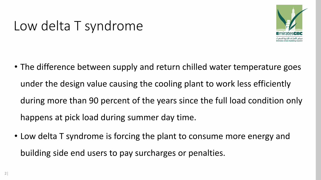
• The difference between supply and return chilled water temperature goes
under the design value causing the cooling plant to work less efficiently
during more than 90 percent of the years since the full load condition only
happens at pick load during summer day time.
• Low delta T syndrome is forcing the plant to consume more energy and
building side end users to pay surcharges or penalties.

Reasons of Low delta T syndrome
3│
Main reasons: Design & selection, commissioning, maintenance & operation.
1. Design & selection: Oversized or undersized cooling coils & control valves will cause overflows and reduce exchange efficiency resulting in low return temperature.
2. Lack of maintenance of the equipment eg. Dirty air filter or coils (outside fins or inside the coil) with reduce the exchange efficiency and cause low return temperature.
3. Commissioning: wrong hydronic balancing and pump optimization will result in over pumping during part load causing low return temperature.
……………………Example of the above listed below………………………………

Design & Selection
4│
Common cases: valve size = pipe size
This will cause the valve to have lower pressure drop and reduced authority that will directly affect the flow control range and the valve will work as ON/OFF instead of Modulating.
Cooling coil: oversized cooling coil might lead to bigger tube when modulating and the water velocity will be less than the minimum of 0.3m/s (min 0.3m/s & max 1.5m/s) below 0.3m/s the flow will not be turbulent for proper exchange and lead to reduced return temperature.

Maintenance
5│
Poor maintenance lead to lower exchange and discomfortDirty air filter lead to inefficient exchange & low return chilled water temperature.Blocked strainer lead to less flow which will push the controller to open the valve further and cause overflow.

HYDRONIC SYSTEMS – VARIABLE FLOW
Moverflow
overflow
overflow
M
M
M
M
M
Moverflow
overflow
overflow
M
M
overflow
overflow
overflow
more
more
more
more
more
more
more
more
Flow
Kv
Control Valve Character
Wasted range
even
even
even
even
even
6°C
6°C
Master Partner Valve
Partner Valves

7
Q = Kv √∆PKv = Q/ √∆PWhereQ : flow rate m3/hr∆P : pressure drop across the control valve in barKv : flow coefficient of the control valve

• A calculation done to determine the performance of the control valve’s characteristic & capability to control against system pressure.
8
Δp open valve
Δp open valve + Δp system
(x 100%)β=

Flow
Lifting
0% 25% 50% 75% 100%
0%
25%
50%
75%
100%
Line
ar
Valv
e
Lifting
Flow
0% 25% 50% 75% 100%
0%
25%
50%
75%
100%
EQM
Va
lve
Excellent Good Moderate Poor Unacceptable
1 – 0.76 0.75 – 0.51 0.5 – 0.26 0.25 – 0.11 0.1 - 0
Accuracy & Stability Table

10
C
C
VSD
∆P
C
C
C
C
35kPa
5 kPa300pa/m
100m
x = 30kPa
?
Δp open valve
Δp open valve + Δp systemβ = = 0.5
?
30+5+35+?
β =
70
140β = = 0.5
Pipe pressure drop
25m³/h
70
30+5+35+70
β =
Indexunit
140 kPa
70kPa

Control Valves sizes
1.8 Kvs = DN104.0 Kvs = DN156.3 Kvs = DN2510 Kvs = DN3216 Kvs = DN4025 Kvs = DN5040Kvs = DN6563Kvs = DN80
70
30+5+35+70β = = 0.5
70
140β = = 0.5
Valve Authority Requirement
Authority not optimum
Recommended = 0.5

Mechanical DP Controllers: Diffirential Pressure Control Valve (DPCV)

- Right distribution of pressure between branches
- Minimize mutual influence from branches- Improve authority but not totally if the
quantity of controlled terminal units is high.
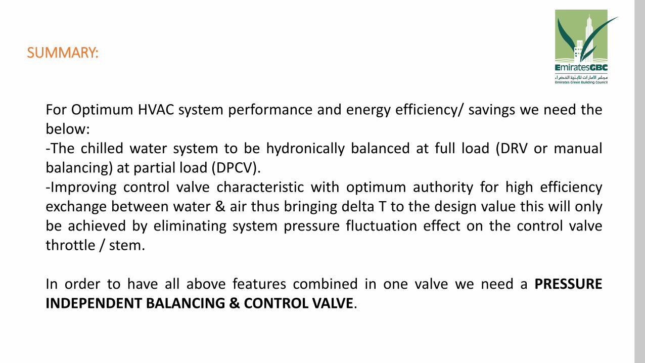
SUMMARY:
For Optimum HVAC system performance and energy efficiency/ savings we need thebelow:-The chilled water system to be hydronically balanced at full load (DRV or manualbalancing) at partial load (DPCV).-Improving control valve characteristic with optimum authority for high efficiencyexchange between water & air thus bringing delta T to the design value this will onlybe achieved by eliminating system pressure fluctuation effect on the control valvethrottle / stem.
In order to have all above features combined in one valve we need a PRESSUREINDEPENDENT BALANCING & CONTROL VALVE.

Water Flow Direction
Manual Presetting Valve Control Valve ∆P Controller Valve
Copper Tubing to transmit Pressure into the Chamber

Low pressure
Water Flow Direction
Manual Presetting Valve Control Valve ∆P Controller Valve
Copper Tubing to transmit Pressure into the Chamber
∆P
High pressure
∆P
30kPa30kPa50kPa 50kPa20kPa
transferred

What is the AB-QM?
The AB-QM is a Pressure Independent Balancing and Control Valve (PIBCV):
• Control valve
• Automatic balancing function

How does the AB-QM work
• The top part of the AB-QM is a control valve

How does the AB-QM work
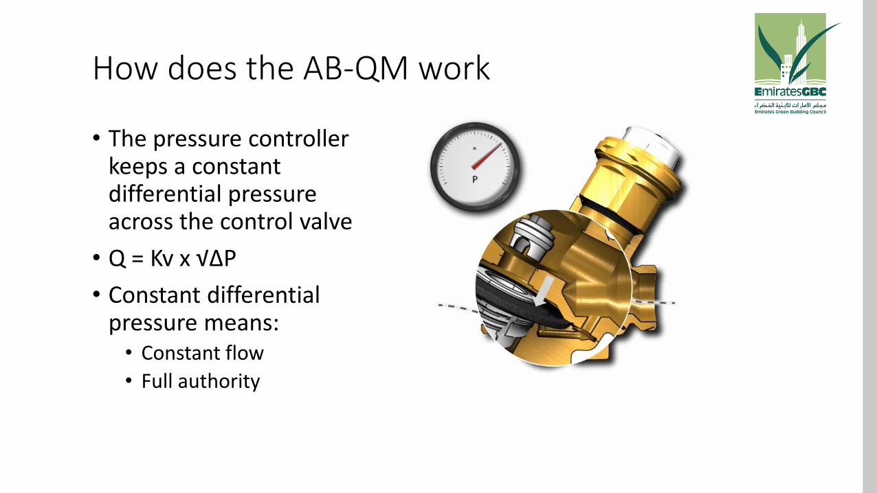
• The bottom part of the AB-QM is a differential pressure controller that keeps a constant differential pressure across the control valve independent of pressure fluctuations in the system
How does the AB-QM work
• The pressure controller keeps a constant differential pressure across the control valve
• Q = Kv x √∆P
• Constant differential pressure means:• Constant flow
• Full authority


Product range
AB-QM &
TWA-Z /HF
AB-QM& ABN/M A5
LOG/LIN
AB-QM& AME/V
110/120 NL/X
AB-QM& AME 435QM
AB-QM& AME 55QM
AB-QM &AME 85QM

The AB-QM can be combined with a large range of actuators• For superb control performance use gear actuators with
the following unique features:
• Self calibration to the stroke of the AB-QM
• Lin/Log/alpha setting to make the same valve/actuator combination linear or logarithmic
• High rangeability (256 steps at any preset)
• Instant response to change in control signal
0V 10V
P Q
t
calibrationLin/Log/alpha
highrangeability
instantresponse
0V 0.5V
P

Applications
• AHU, Heating/Cooling

Applications
• Fancoil unit, Heating/Cooling

Applications
• Heat Exchangers

Less calculations
Selection of the AB-QM is based purely on
the flow:
• No KV calculations
• No need to calculate authority

Less Mounting/Installation
Mounting cost• Installation time DN15 valve
approx. 70 minutes
• Installation time DN40approx. 80 minutes
• Installation time DN80approx. 120 minutes
• Less commissioning time (normally atleast 30 min./valve)
• No delay of handover
• Phased handovers

How does the AB-QM save energy
• Potential savings• pumping
• ∆T to chiller
• Temperature setting

Energy savings on pumping
Pump head (Bar)
Flow(m3/h)
Days per year
Load profile
0,8 120 285 Full load
0,8 100 285 Standard
1,6 120 285 Standard
Energy per year
Energy cost per valve per
year (€)
31000 15,5
9900 5,0
22900 11,5
• 3-way valves require full load all the time
• PICV allows more precise flow limitation
• Traditional control requires bigger pumphead to achieve sufficient authority
3-way
AB-QM
2-way
NB: Calculations based on an average installation with 100m3/h and 200 DN20 valves with a flow of 500 l/h. 1 kW = 0,1 Euro

0,0
2,0
4,0
6,0
8,0
0 20 40 60 80 100
% of load
CO
P
AB-QM Traditional control valve
0,50
0,60
0,70
0,80
0,90
1,00
0 20 40 60 80 100
% of load
kW
/to
n
AB-QM Traditional control valvel Traditional
AB-QM
Design
Energy saving on chiller
• A chiller is designed for 100% load but operates mostly (in case of traditional control valve) at 40% due low ∆T syndrome. Consequently additional chillers will be started by the control system to achieve requested cooling.
• AB-QM will increase chiller performance significantly, as we avoided overflow and thus are we able to increase ∆T

Energy saving on Chiller
• Higher (designed) return allows chiller to run more efficeint
• Variable primary hydronics
• allow to run chillers in so called maxCap
• more demanding to control valves
• To ensure maximum efficiency make sure to maximize ΔT

Increasing ∆T leads to higher energy efficiency
• Higher return temperature (with 3 K) for chillers (cooling system) results >10% energy saving
• Lower return temperature (< 60ºC) for condensing boilers (heating system) results in ~10% energy saving

Energy saving on the temperature setting• What constitutes a comfortable temperature is individual and varies through the day
• Imprecise control increases the chance of discomfort
• Discomfort causes complaints and increased use of energy
• By stabilizing the control the temperature can be optimised
• increasing the setting with 1K saves 10 to 16% of energy (Cooling)

Energy saving summary
• By reducing overflows the pump can run on a lower speed
• By improving the DT of the installation the efficiency of the chiller can be improved
• By increasing the performance of the control the temperature setting can be optimised

Danfoss NovoCon® smart actuator conceptThe best way to cut back on installation costs

Next stepBased on extensive customer feedback:
• More efficient builidng process
• More automation (data)
• Higher demands• Comfort• Energy efficiency
The result:
Smart actuator NovoCon®

4 system components combined in 1ActuatorNovoCon® is a highly accurate multi-functional actuator
Bus communication deviceNovoCon® enables more than flow control via Fieldbus
Flow indicatorNovoCon® indicates flow
through the AB-QM valve
Online Data info
to compare building performance

Flexibility in connections
*Twisted pair cabling canceling
out electromagnetic interference (EMI)
NovoCon® digital portRed: PowerBlack: Common ground for powerand bus signal wireGreen: ‘+’ non-inverting signal wire *Green/White: ‘-‘ inverting signal wire *
Digital port for daisy chain

Flexibility in connections:• BACnetTM/Modbus
datacommunication
• 24 V connection
• Daisy chaining
• Analog signal input / output
• Temperature sensor wired or direct sensor

Remote setting design flow
275
270
Design flow
l/h
NO MANUAL PRE-SET
Digital PRE-SET

Limit
Max. stroke
50%
Remote setting design flow
225
Design flow
l/h
Example:
Designflow: 225 [l/h]
Maximum flow AB-QM DN15: 450 [l/h]
Limitation stroke NOVOCON®: Designflow
Maximum flow∙100 [%]
120%100%
0%
50%

Remote features • Flushing program
• De-air program
50%

Remote feature:Flushing program 50%120%
100%
0%
50%
60 min.

Remote feature:De-air program 50%120%
100%
0%
50%
5 x

Remote status feedback • Error: No signal
• Error: Calibration
• Warning high temperature electronics
• Warning abnormal supply voltage
• Closing error due to obstruction
• No 0-10V control signal

Energy ManagementMin. Delta T Management
Description:
Smart actuator overrides the DDC control signal and maintains a minimum temperature difference between the flow and return temperatures by closing the valve when the user defined minimum is not achieved. When the flow temperature increases/decreases, so will the calculated minimum setpoint for the return temperature. This always ensures a minimum energy transfer to the FCU irrespective of the flow temperature.
Time
°C
Time
l/h
CHW Flow
CHW Return
NovoCon overrides to maintain min. ∆T
Min ∆T setting

FCU Application – Min. Delta T Management
Description:• Actuator being primarily controlled by a DDC bus control signal in % valve
opening.• Actuator will override the DDC control signal when the user defined delta T is
not achieved and the valve will begin to close.• Actuator is gathering energy information about the FCU via 2 PT1000 pipe
sensors.
Note:• BV:22 will be activated if the sensors are missing or not connected properly.• BV:23 will be activated to alert the user the user that this override function is
active.• BV:24 will be activated to alert the user if the user defined min. ∆T is out of the
achieveable range.• ΔT & temperature sensing units may be changed to °F via MSV:23.• Logged Energy kWh may be changed to MJ or kBTU via MSV:27.

Energy ManagementSet Delta T Control
Description:The smart actuator overrides the DDC control signal and maintains a constant temperature difference between the flow and return temperatures by opening and closing the valve when the user defined ∆T is exceeded or not achieved. When the flow temperature increases/decreases, so will the calculated ∆T setpoint for the return temperature. This always ensures a constant ∆T accross the FCU irrespective of the flow temperature.
Time
°C
Time
l/h
CHW Return
CHW Flow
NovoCon doesnt accept DDC flow control and maintains constant ∆T
Set ∆T band

FCU Application – Set Delta T Control
Description:• Actuator is primarily controlling itself and overwriting DDC bus control signal in
% valve opening.• Actuator will open and close accordingly in maintaining the user defined set ∆T
value.• Actuator is gathering energy information about the FCU via 2 PT1000 pipe
sensors.
Note:• BV:22 will be activated if the sensors are missing or not connected properly.• BV:23 will be activated to alert the user the user that this override function is active.• BV:24 will be activated to alert the user if the user defined set ∆T is out of the
achieveable range.• ΔT & temperature sensing units may be changed to °F via MSV:23.• Logged Energy kWh may be changed to MJ or kBTU via MSV:27.

Remote alpha setting for optimal control• Optimal control is possible, if we have linear response of system. Characteristic
of HEX can be compensated with characteristic of actuator by appropriate α value.
• On NovoCon you can set the value remotely using BACnet command.
• α=0.2 (logarithmic), α=1 (linear).
Relationship between HEX (full line) and valve+actuator (dashed line) characteristic

LED bar on NovoConTM
Network statusBACnet(RS485) activity
Valve positionIndication of valve position
MovementLED’s show if NovoconTM is
opening or closing
Errors Abnormal voltage supply,
internal temperature, obstruction during closing
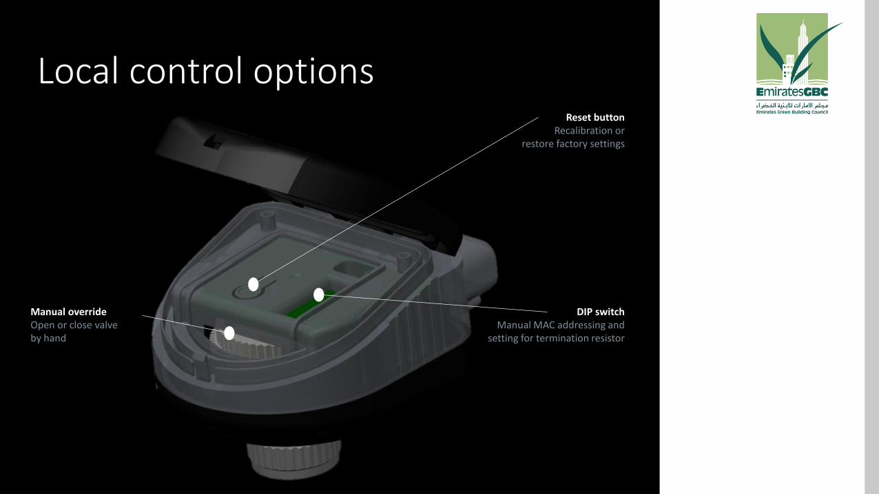
Local control options
Manual overrideOpen or close valve by hand
Reset buttonRecalibration or
restore factory settings
DIP switch Manual MAC addressing and
setting for termination resistor

Flow indication
How is it possible ?Precision stepper motor for precise spindle positionMaintaining constant differential pressure

Select and adapt the Smart actuator Daisy-chaining
Power boosterEnable terminationby DIP-switch
Bus communicationand power supply
• Additional voltage booster each 7 – 11 NovoCon’s.
• Chain max. 64 pcs

Sticker on the smart actuator
NovoconTM S Hybrid003Z8500
H100 V99
3008820
0010434 Made in Sweden
Power 24VAC/DC, 50/60 HZ
Force: 90N, Stroke: 7mm, Speed: 3-24 s/mm
Consumption: 3.25VA running, Standby 0,75W
Control signal: 0-10V/0-20mA/BACnet MS/TP
IP54/40, -10T55
H100 V99
3008820
0010434
Actuator for AB-QM DN 10 - 32
"
Serial Number of NovoCon S actuatorUnique ID (last 7 digits)

Conclusions
1 clickto flush hundreds of AB-QM valves
• Faster design with AB-QM• Faster installation • Faster, remote commissioning• Energy optimisation• Faster problem location• Faster remote maintenance

Time is the biggest saving
Alarms and status are feedback to the Building Automation System via Fieldbus
Remote system verification:
✓wiring to actuator
✓connection to valve
✓valve pre-setting
✓valve operation
No need to visit site
LEDs on the side of the smart actuator give local status feedback

Thank You