Efikasni KGH sistemi u bolnicama Efficient HVAC Hospitals
34
lindab | we simplify construction Efikasni KGH sistemi u bolnicama Efficient HVAC systems in Hospitals Egon Venko, Boris Čabarkapa, Lindab Power point presentation Supported by Kristina Jager and Ana Kurtanjek
Transcript of Efikasni KGH sistemi u bolnicama Efficient HVAC Hospitals
lindab | we simplify construction
Efikasni KGH sistemi u bolnicama
Efficient HVAC systems in Hospitals
Egon Venko, Boris Čabarkapa, Lindab
Power point presentation Supported by Kristina Jager and Ana Kurtanjek
lindab | we simplify construction
Providing comfort in patient rooms
Contents
General technical requirements
The subject of the project
Options for individual systems with LCC
Lindab system solutions at UMC Ljubljana
Lindab system solution for OP rooms
lindab | we simplify construction
General technical requirements-hospitals
Preventing the spread of contagions is an important task for ventilation in hospitals. In some types of care, low levels of contagions in the air are absolutely crucial to the outcome, for example in transplants and patients with burn injuries. The reliability of each component is therefore absolutely crucial in ensuring the ventilation system is completely safe. Operating theatres and laboratories are complex systems with extreme hygiene requirements on materials and equipment. At the same time, all of these rooms are individual projects that require the utmost precision and flexibility – both as regards design and adaptation to the project’s specific needs.
Lindab can meet the very highest technical requirements in places where maximum hygiene safety has to be assured, such as operating theatres, laboratories and intensive care wards.
lindab | we simplify construction
General technical requirements-hospitals
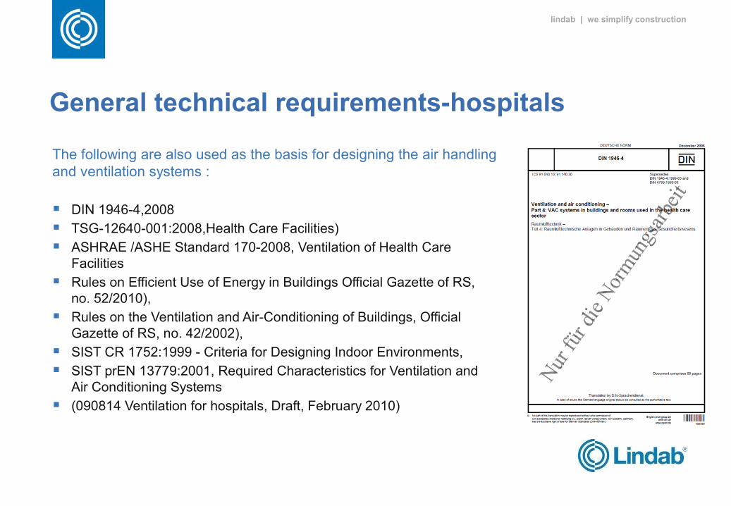
The following are also used as the basis for designing the air handling and ventilation systems :
DIN 1946-4,2008
TSG-12640-001:2008,Health Care Facilities)
ASHRAE /ASHE Standard 170-2008, Ventilation of Health Care Facilities
Rules on Efficient Use of Energy in Buildings Official Gazette of RS, no. 52/2010),
Rules on the Ventilation and Air-Conditioning of Buildings, Official Gazette of RS, no. 42/2002),
SIST CR 1752:1999 - Criteria for Designing Indoor Environments,
SIST prEN 13779:2001, Required Characteristics for Ventilation and Air Conditioning Systems
(090814 Ventilation for hospitals, Draft, February 2010)
lindab | we simplify construction
General technical requirements-patient room
Maintaining the appropriate temperature and humidity has a favorable effect on the well being of the patients and good ventilation ensures the quality of the indoor environment and decreases the health hazard level for people in the room. Forced ventilation with a supply of fresh, purified air decreases the number of germs in the room and helps decrease infections.
Therefore, in hospital departments, maintaining an appropriate indoor environment can even shorten the period of inpatient stay or hospitalization.
The task of air handling and ventilation in patient rooms is maintaining the appropriate temperature and humidity in the room, regardless of external parameters, and the supply of fresh air provides the appropriate quality of air in the room and prevents the intrusion of outside air into the room.
It should operate as quietly as possible and the operating and maintenance costs should be as low as possible.
lindab | we simplify construction
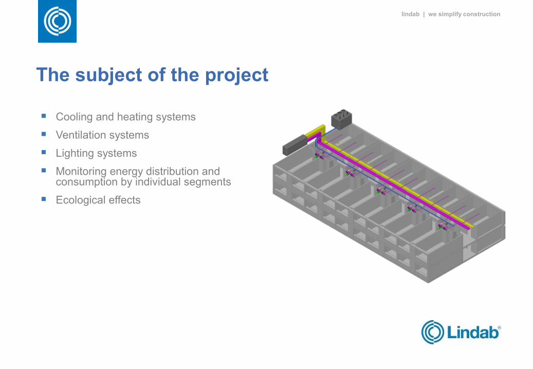
The subject of the project
Cooling and heating systems
Ventilation systems
Lighting systems
Monitoring energy distribution and consumption by individual segments
Ecological effects
lindab | we simplify construction
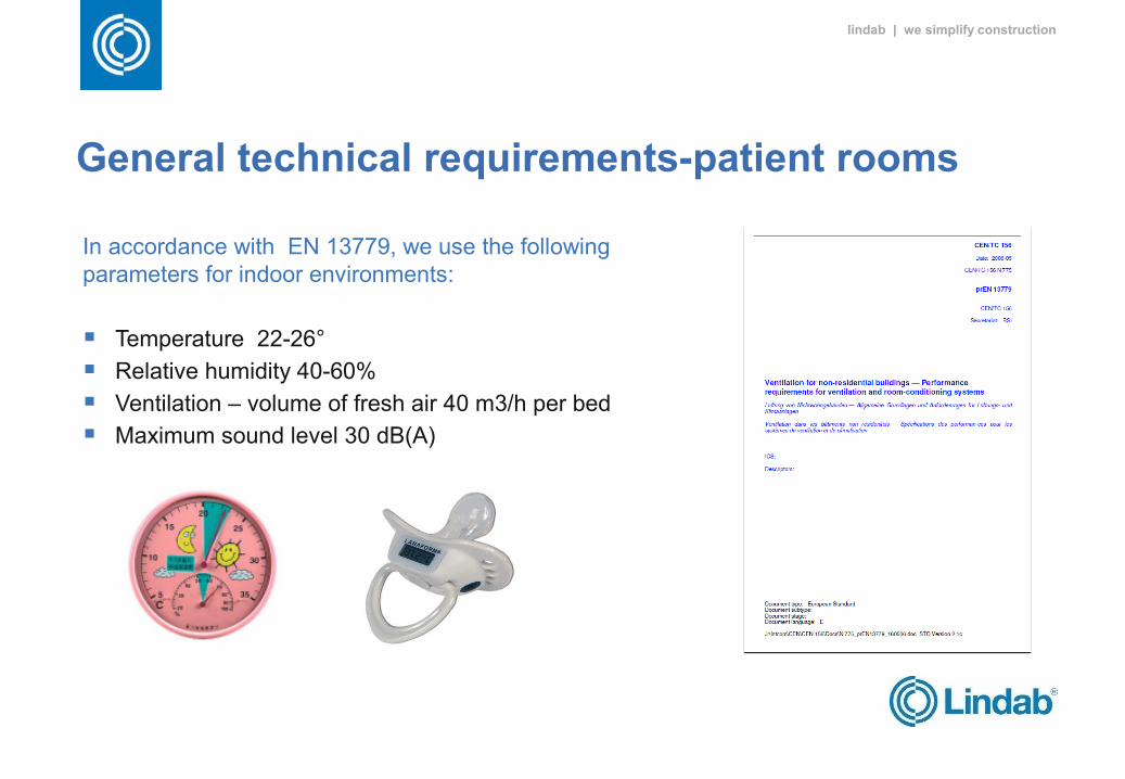
General technical requirements-patient rooms
In accordance with EN 13779, we use the following parameters for indoor environments:
Temperature 22-26°
Relative humidity 40-60%
Ventilation – volume of fresh air 40 m3/h per bed
Maximum sound level 30 dB(A)
lindab | we simplify construction
Options for individual systems
Suitable comfort in the room can be achieved with various systems.
Four systems are presented bellow:
A. radiator heating, cooling with Climmy fan coils, 2-pipe systems, natural ventilation (windows)
B. heating with Climmy fan coil, 4-pipe system and mechanical ventilation
C. heating/cooling with Climmy ceiling fan coil, 4-pipe system and mechanical ventilation
D. radiator heating, cooling with chilled beams in a set together with mechanical ventilation
lindab | we simplify construction
Options for individual systems – version A
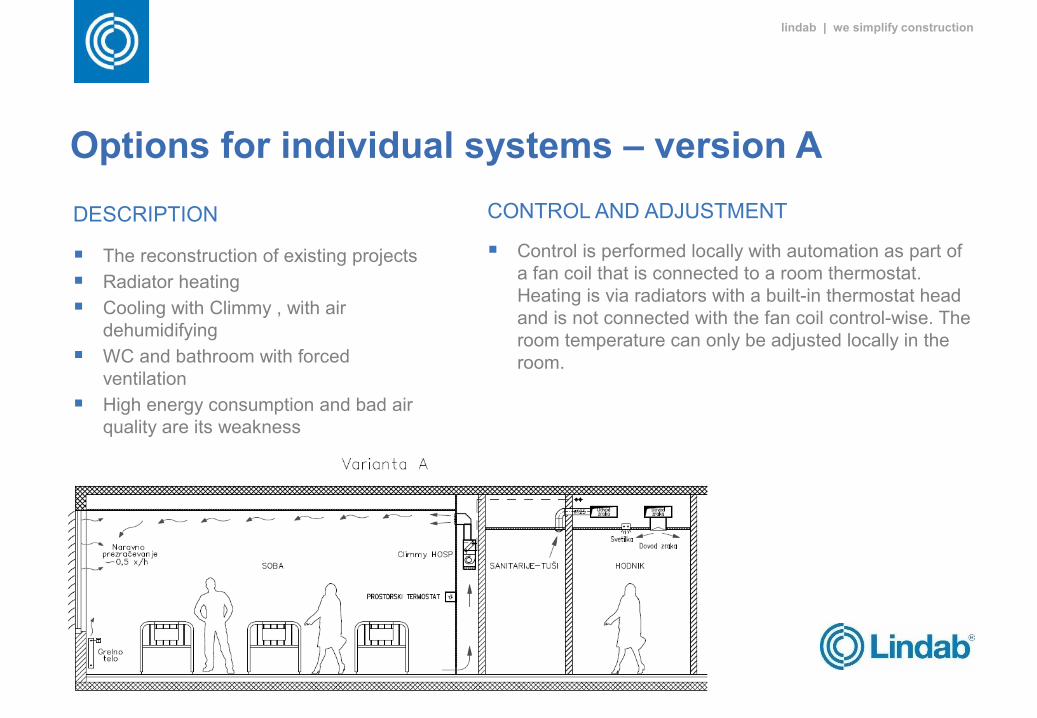
DESCRIPTION
The reconstruction of existing projects
Radiator heating
Cooling with Climmy , with air dehumidifying
WC and bathroom with forced ventilation
High energy consumption and bad air quality are its weakness
CONTROL AND ADJUSTMENT
Control is performed locally with automation as part of a fan coil that is connected to a room thermostat. Heating is via radiators with a built-in thermostat head and is not connected with the fan coil control-wise. The room temperature can only be adjusted locally in the room.
lindab | we simplify construction
Options for individual systems – version B
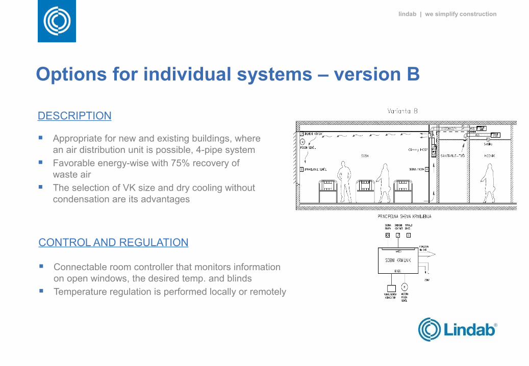
DESCRIPTION
Appropriate for new and existing buildings, where an air distribution unit is possible, 4-pipe system
Favorable energy-wise with 75% recovery of waste air
The selection of VK size and dry cooling without condensation are its advantages
CONTROL AND REGULATION
Connectable room controller that monitors information on open windows, the desired temp. and blinds
Temperature regulation is performed locally or remotely
lindab | we simplify construction
Options for individual systems – version C
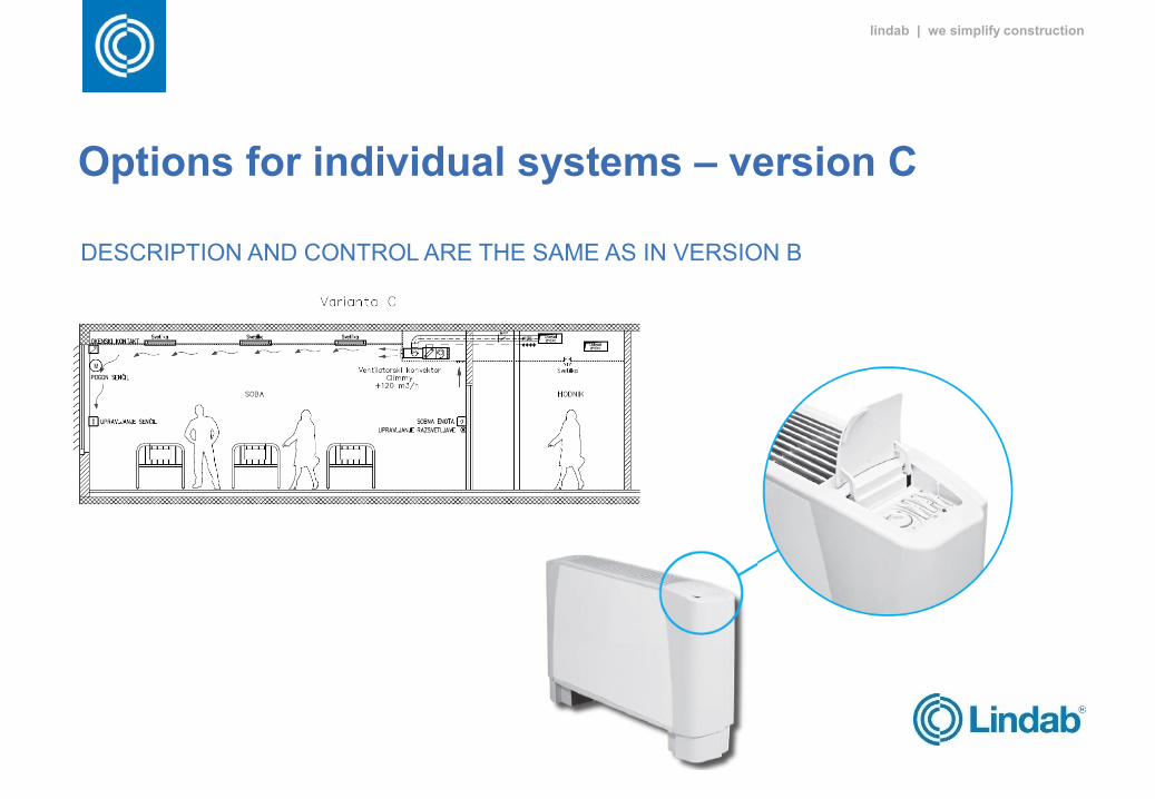
DESCRIPTION AND CONTROL ARE THE SAME AS IN VERSION B
lindab | we simplify construction
Options for individual systems – version D
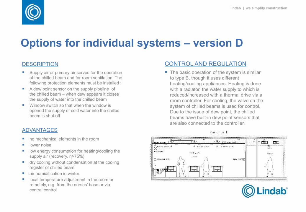
DESCRIPTION
Supply air or primary air serves for the operation of the chilled beam and for room ventilation. The following protection elements must be installed :
A dew point sensor on the supply pipeline of the chilled beam – when dew appears it closes the supply of water into the chilled beam
Window switch so that when the window is opened the supply of cold water into the chilled beam is shut off
ADVANTAGES
no mechanical elements in the room
lower noise
low energy consumption for heating/cooling the supply air (recovery, η>75%)
dry cooling without condensation at the cooling register of chilled beam
air humidification in winter
local temperature adjustment in the room or remotely, e.g. from the nurses’ base or via central control
CONTROL AND REGULATION
The basic operation of the system is similar to type B, though it uses different heating/cooling appliances. Heating is done with a radiator, the water supply to which is reduced/increased with a thermal drive via a room controller. For cooling, the valve on the system of chilled beams is used for control. Due to the issue of dew point, the chilled beams have built-in dew point sensors that are also connected to the controller.
lindab | we simplify construction
Options for individual systems – version D-hygiene
CBs are easy to clean
No filters in CB´s that have to be cleaned
There is no condense water that should be handled in ACB´s, therefore no cleaning of drain pans necessary
Moving parts in a FCU creates lower hygiene
CB´s only need to be cleaned every 5 years
ACB´s are using dry cooling (water temperature above dew point) Since using dry cooling the risk of condensation water is limited No need for condensation drainage in ACB´s Since no risk for condensation therefore also no risk for leakage problems within the drainage The condensation process is consuming energy which result in a higher energy consumption
for FCUs Control is needed to keep the water temperature over dew point is necessary when using
ACB´s
lindab | we simplify construction
Options for individual systems – version D-Air velocities / Draught risk
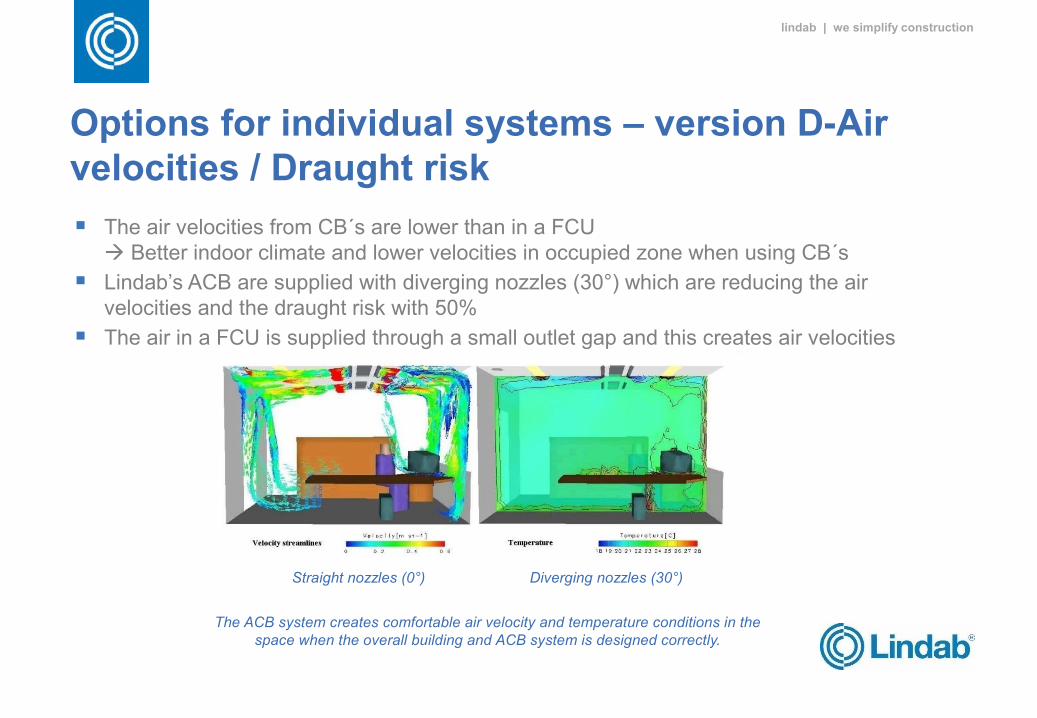
The air velocities from CB´s are lower than in a FCU Better indoor climate and lower velocities in occupied zone when using CB´s
Lindab’s ACB are supplied with diverging nozzles (30°) which are reducing the air velocities and the draught risk with 50%
The air in a FCU is supplied through a small outlet gap and this creates air velocities
Straight nozzles (0°) Diverging nozzles (30°)
The ACB system creates comfortable air velocity and temperature conditions in the space when the overall building and ACB system is designed correctly.
lindab | we simplify construction
System Characteristics for the Effective Cooling of Patient Rooms
Temperature and air humidity The system works on the principle of high temperature cooling (the cold water temperature is 12–17 °C) The option of a system without condensation (without the possibility of water stagnation) The option of a later supply of fresh air for ventilation from the central air handling unit Adaptability of the system for later renovation of the glazing and facade
Sound A concealed design of the cooling system, which basically means a lower noise level Highly effective centrifugal fans with several speeds
Air velocity The option of dispersing the stream of supplied air, even after the installation of the system Filtration of recirculating air Compliance with the Slovenian rules on ventilation and the SIST EN 7730 standard for comfort in the
room, and the draft of the CEN/TR 16244:2011 standard – Ventilation for Hospitals
lindab | we simplify construction
LCC Analysis1. ENERGY
The required annual energy for maintaining the indoor environment of a patient room is composed of energy for maintaining the temperature environment and energy for ventilating the room.
Energy for maintaining the temperature environment depends on the building envelope, the protection of glass surfaces against solar radiation and internal gains.
2. COSTSCapital costs - investmentCosts of energy - electrical energy, thermal energy, water consumption for humidificationOperating costs - management, maintenance, inspectionsOther costs - insurance, contributions, management costs
3. INVESTMENT ESTIMATELike energy, the investment in the system for maintaining the indoor environment is divided into two systems: the water part maintains the thermal environment and the air part takes care of the air quality in the room.
lindab | we simplify construction
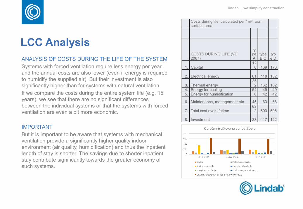
LCC AnalysisANALYSIS OF COSTS DURING THE LIFE OF THE SYSTEM
Systems with forced ventilation require less energy per year and the annual costs are also lower (even if energy is required to humidify the supplied air). But their investment is also significantly higher than for systems with natural ventilation.
If we compare the costs during the entire system life (e.g. 15 years), we see that there are no significant differences between the individual systems or that the systems with forced ventilation are even a bit more economic.
IMPORTANT
But it is important to be aware that systems with mechanical ventilation provide a significantly higher quality indoor environment (air quality, humidification) and thus the inpatient length of stay is shorter. The savings due to shorter inpatient stay contribute significantly towards the greater economy of such systems.
Costs during life, calculated per 1m2 room surface area
COSTS DURING LIFE (VDI 2067)
type A
type B,C
type D
1. Capital120 169 176
2. Electrical energy 61 118 102
3. Thermal energy352 162 162
4. Energy for cooling 54 49 495. Energy for humidification 0 42 42
6. Maintenance, management etc. 45 63 66
7. Total cost over lifetime632 603 596
8. Investment 83 117 122
lindab | we simplify construction
System Solution at UMC Ljubljana
Temperature and air humidity
The indoor temperature in the room is 26 °C
50% relative humidity
Sound
The marginal sound pressure at a height of 1.2m from the floor and 0.9m from the outer wall of the room at medium fan speed is 42 dB(A) or NC 37
Air velocity
Air velocity in the habitable zone is below the limit of 0.2 m/s (which the majority of people do not perceive as a draft)
Ensured Coanda effect – the attraction of the stream of cold air to the ceiling of the room by using a highly inductive supply component (local velocities are high enough to provide attraction)
High induction of primary and secondary air, which means a more comfortable temperature field in the habitable zone (no direct entry of cold air into the habitable zone)
Control
Controlling and setting the system with room controllers that are connected to the central control system (CCS). The settings can be locked or a setting can be used only by authorized users.
lindab | we simplify construction
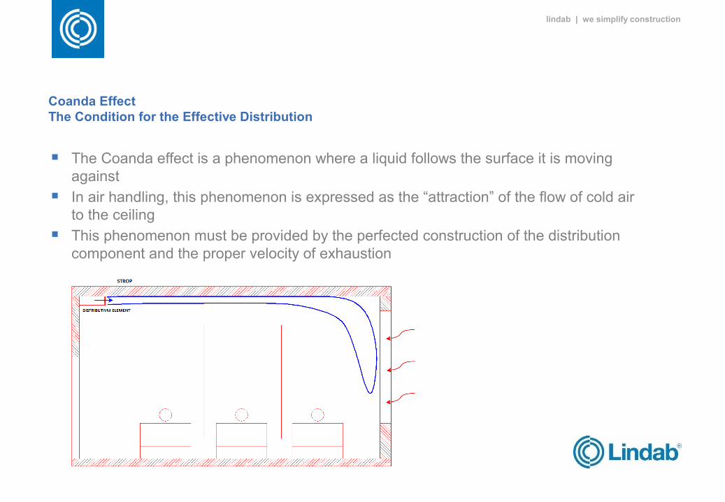
Coanda Effect The Condition for the Effective Distribution
The Coanda effect is a phenomenon where a liquid follows the surface it is moving against
In air handling, this phenomenon is expressed as the “attraction” of the flow of cold air to the ceiling
This phenomenon must be provided by the perfected construction of the distribution component and the proper velocity of exhaustion
lindab | we simplify construction
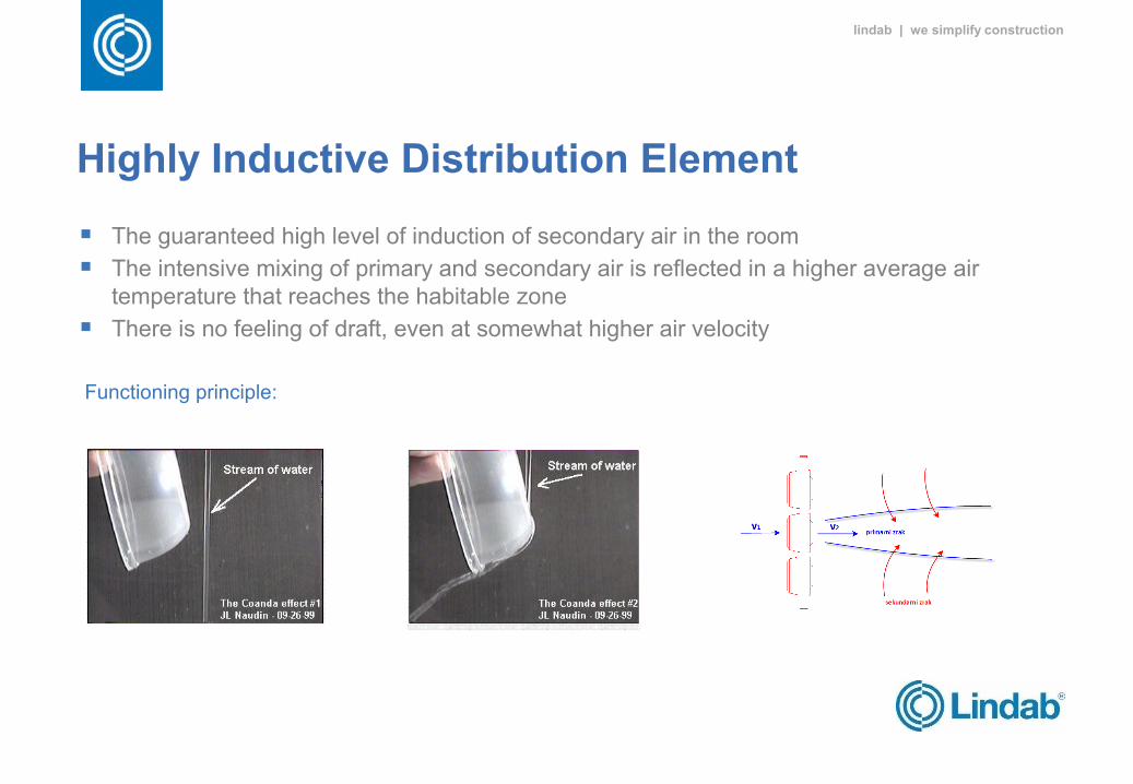
Highly Inductive Distribution Element
The guaranteed high level of induction of secondary air in the room
The intensive mixing of primary and secondary air is reflected in a higher average air temperature that reaches the habitable zone
There is no feeling of draft, even at somewhat higher air velocity
Functioning principle:
lindab | we simplify construction
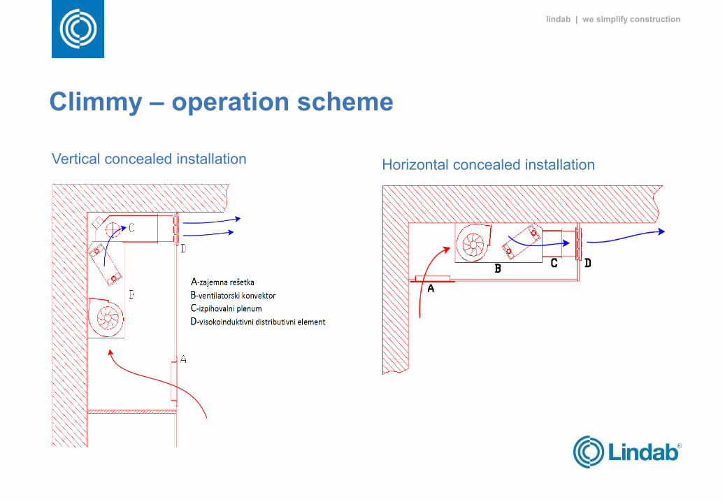
Climmy – operation scheme
Vertical concealed installation Horizontal concealed installation
lindab | we simplify construction
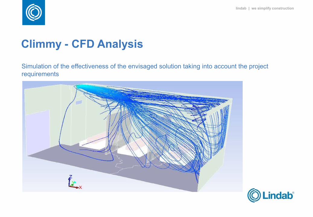
Climmy - CFD Analysis
Simulation of the effectiveness of the envisaged solution taking into account the project requirements
lindab | we simplify construction
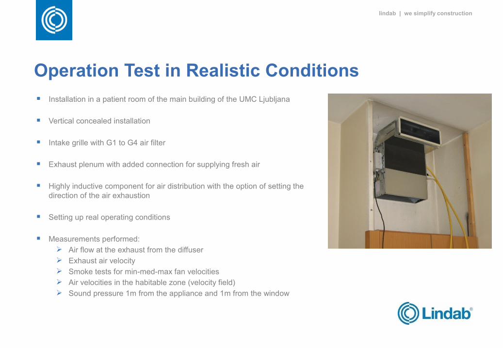
Operation Test in Realistic Conditions
Installation in a patient room of the main building of the UMC Ljubljana
Vertical concealed installation
Intake grille with G1 to G4 air filter
Exhaust plenum with added connection for supplying fresh air
Highly inductive component for air distribution with the option of setting the direction of the air exhaustion
Setting up real operating conditions
Measurements performed: Air flow at the exhaust from the diffuser Exhaust air velocity Smoke tests for min-med-max fan velocities Air velocities in the habitable zone (velocity field) Sound pressure 1m from the appliance and 1m from the window
lindab | we simplify construction
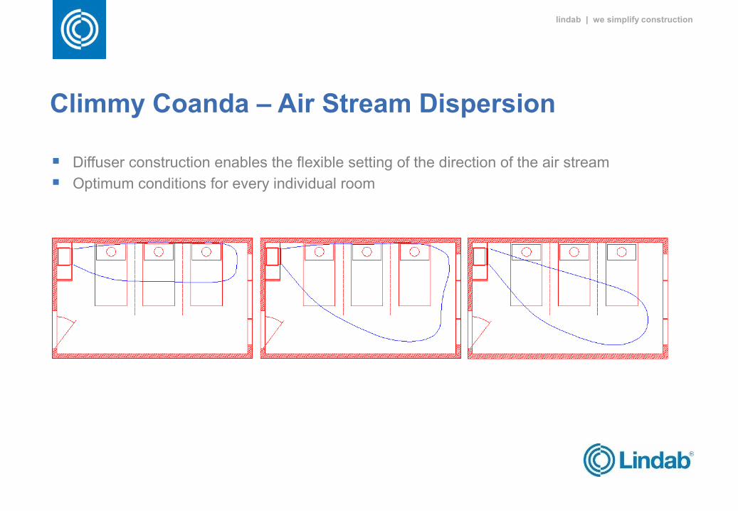
Climmy Coanda – Air Stream Dispersion
Diffuser construction enables the flexible setting of the direction of the air stream
Optimum conditions for every individual room
lindab | we simplify construction
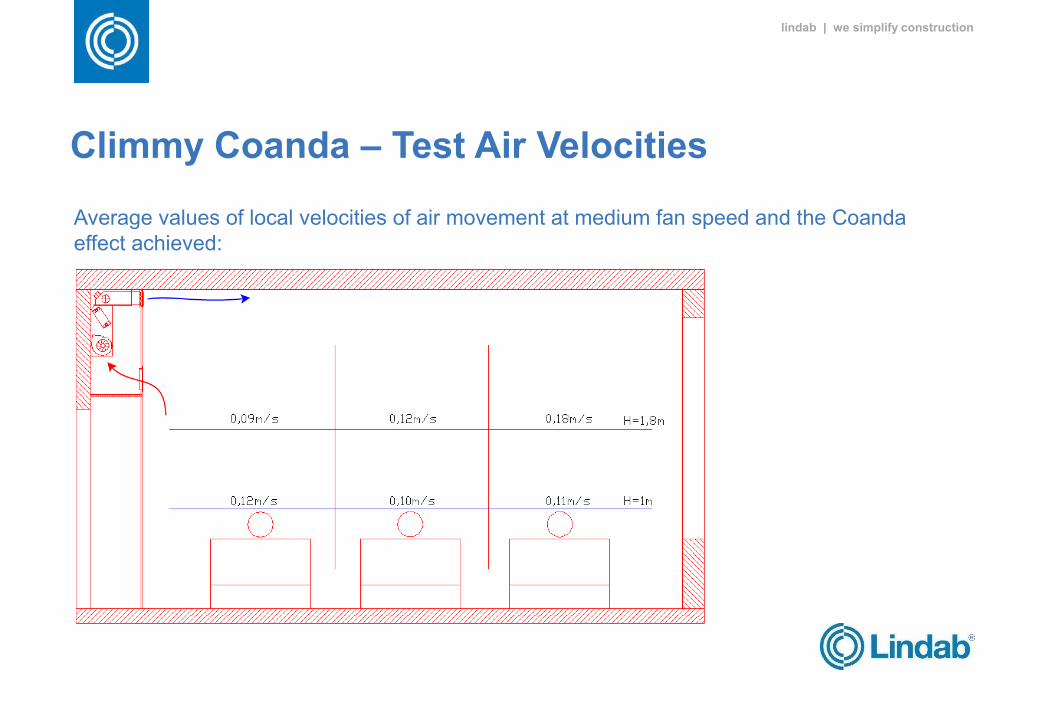
Climmy Coanda – Test Air Velocities
Average values of local velocities of air movement at medium fan speed and the Coanda effect achieved:
lindab | we simplify construction
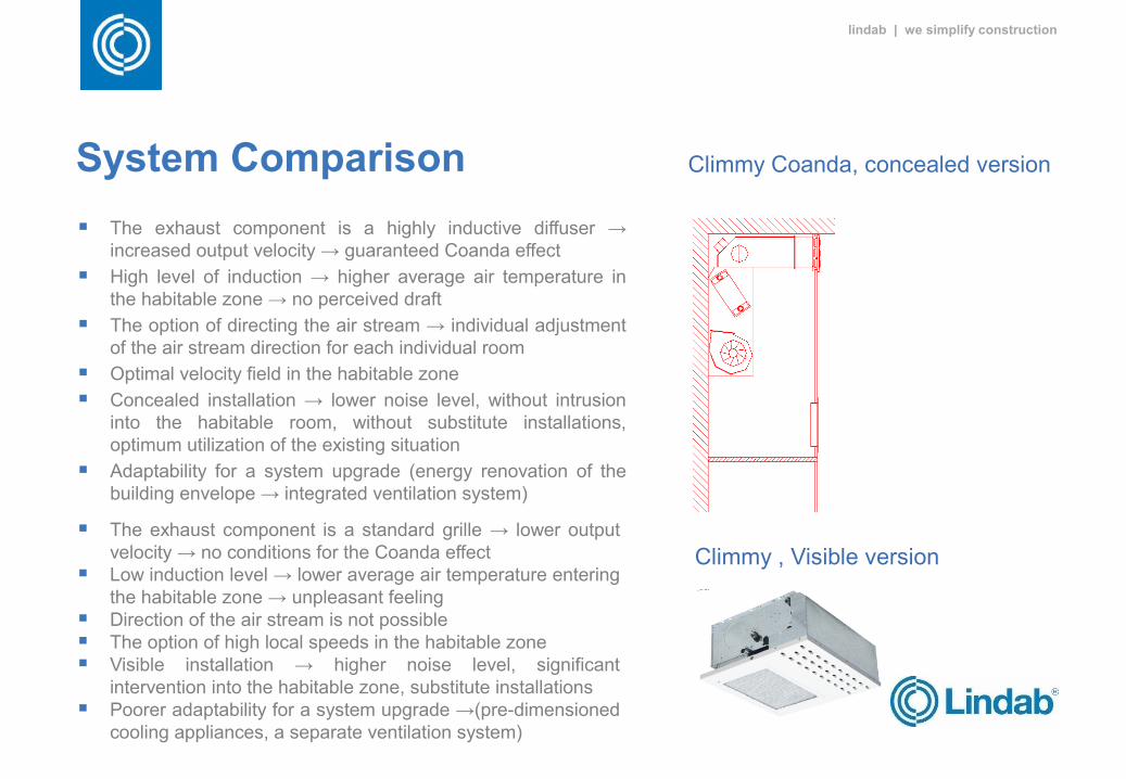
System Comparison
The exhaust component is a highly inductive diffuser → increased output velocity → guaranteed Coanda effect
High level of induction → higher average air temperature in the habitable zone → no perceived draft
The option of directing the air stream → individual adjustment of the air stream direction for each individual room
Optimal velocity field in the habitable zone
Concealed installation → lower noise level, without intrusion into the habitable room, without substitute installations, optimum utilization of the existing situation
Adaptability for a system upgrade (energy renovation of the building envelope → integrated ventilation system)
The exhaust component is a standard grille → lower output velocity → no conditions for the Coanda effect
Low induction level → lower average air temperature entering the habitable zone → unpleasant feeling
Direction of the air stream is not possible The option of high local speeds in the habitable zone Visible installation → higher noise level, significant
intervention into the habitable zone, substitute installations Poorer adaptability for a system upgrade →(pre-dimensioned
cooling appliances, a separate ventilation system)
Climmy Coanda, concealed version
Climmy , Visible version
lindab | we simplify construction
System Comparison
Conclusions:
For the appropriate or effective cooling of hospital rooms, it is strictly necessary to envisage special solutions with units that provide: the Coanda effect a high level of induction local air velocities in the habitable zone below 0.2 m/s
Air handling with standard fan coils does not ensure the required comfort for patients and staff and as such is not a suitable solution
In the event of the energy-related renovation of existing facilities, additional optimization is required due to unfavorable starting conditions. With its laboratories within the framework of the institute, Lindab can carry out a test set-up of the room for various options and, through measurements, determine the best final project solution.
lindab | we simplify construction
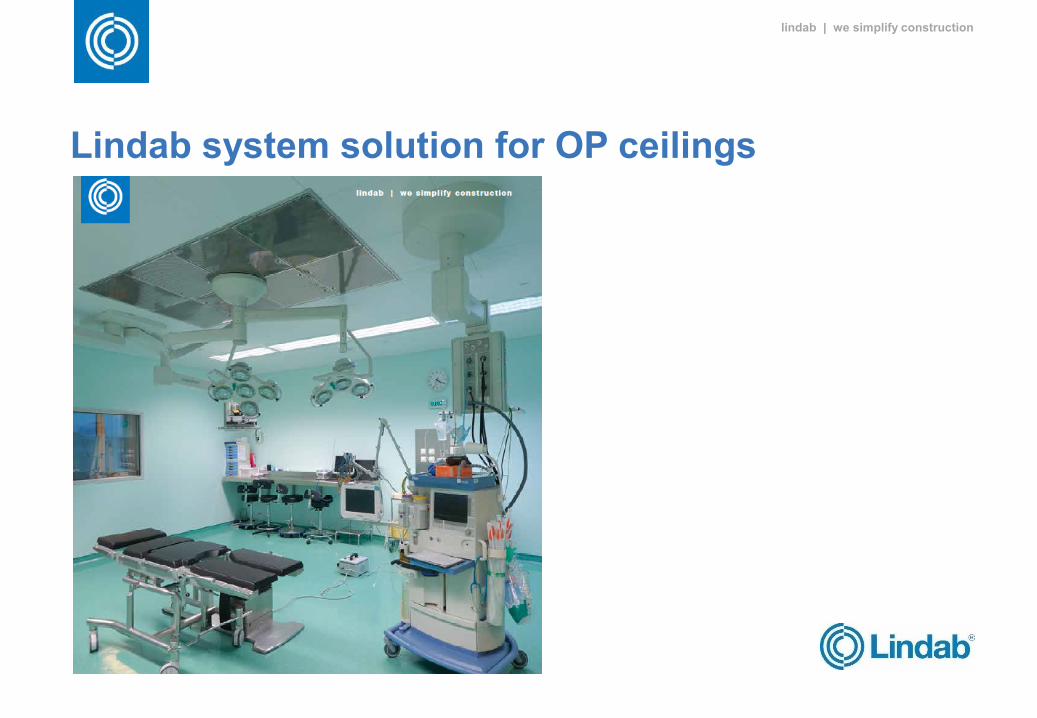
Lindab system solution for OP ceilings
lindab | we simplify construction
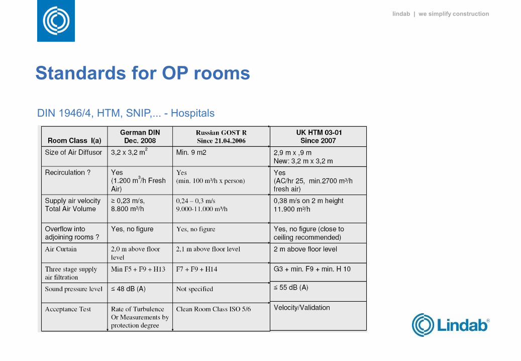
Standards for OP rooms
DIN 1946/4, HTM, SNIP,... - Hospitals
lindab | we simplify construction
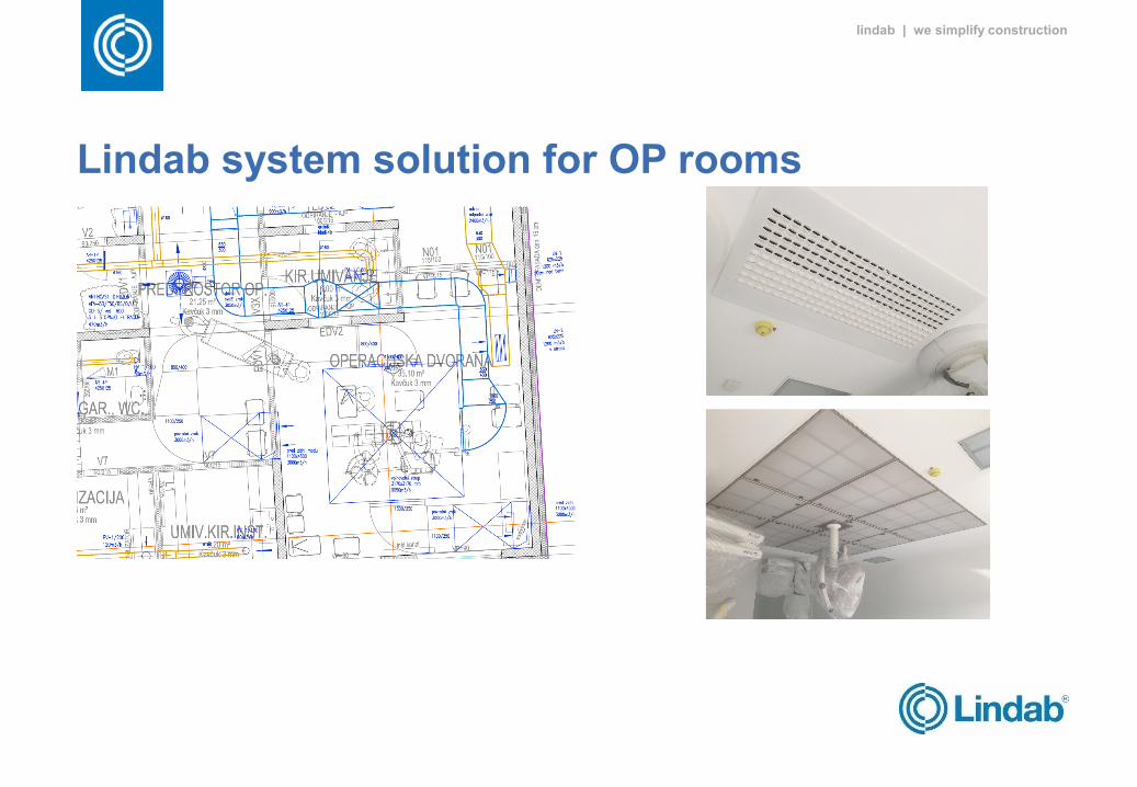
Lindab system solution for OP rooms
lindab | we simplify construction
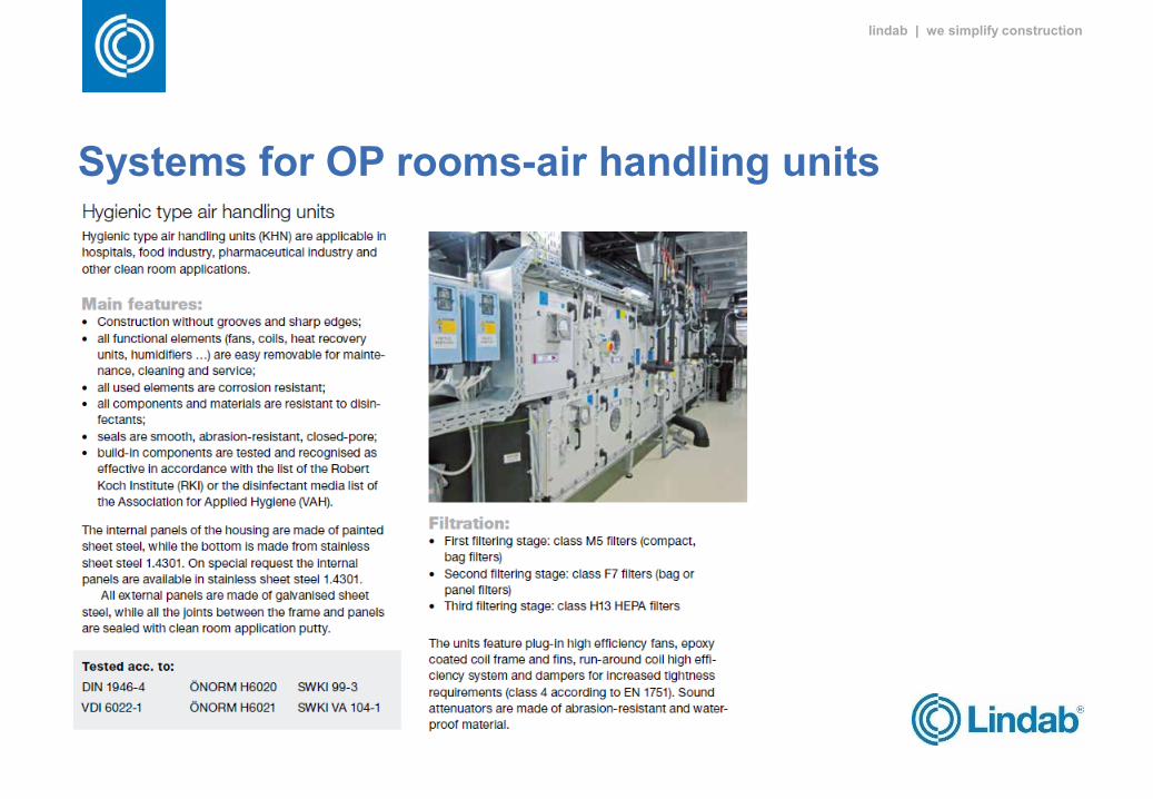
Systems for OP rooms-air handling units
lindab | we simplify construction
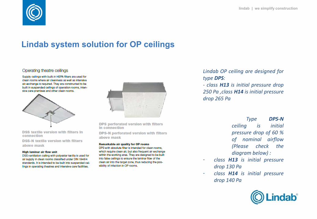
Lindab system solution for OP ceilings
Lindab OP ceiling are designed for type DPS: - class H13 is initial pressure drop 250 Pa ,class H14 is initial pressure drop 265 Pa
Type DPS-N
ceiling is initial pressure drop of 60 % of nominal airflow (Please check the diagram below) :
- class H13 is initial pressure drop 130 Pa
- class H14 is initial pressure drop 140 Pa
lindab | we simplify construction
Conclusion
ZaključakMašinski instalacijski sistemi u zdravstvenim objektima obezbjeđuju: grijanje objekata, snabdijevanje vodom i odvod potrošene vode te ventilaciju i klimatizaciju objekata. Za pravilno planiranje i realizaciju, efikasno djelovanje i jednostavno održavanje mašinskih instalacijskih sistema u zdravstvenom objektu je najznačajniji glavni projekat objekta koji mora uzimajući u obzir sve posebnosti pojedinačnih sistema pravilno locirati i dimenzionirati prostore za njihovu djelovanje i obezbijediti dovoljno prostora za njihove vertikalne i horizontalne instalacijske razvode. Zadatak investitora i projektanata mašinskih instalacija je da uzimaju u obzir međunarodne standarde koji uzimaju u obzir racionalnu potrošnju energije. Pored racionalne potrošnje energije je potrebna i udobnost u prostoru, a veoma značajno je da sa savremenim sistemima maksimalno doprinesemo u smanjenju
bolničkih infekcija koje su veliki problem.

lindab | we simplify construction
WWW.LINDAB.SI