EFFICIENT DESIGN EVALUATION THROUGH THE …
8
ICED15 EFFICIENT DESIGN EVALUATION THROUGH THE COMBINATION OF NUMERICAL AND PHYSICAL COMPUTATIONS Foehr, André G. C.; Stücheli, Marius; Meboldt, Mirko ETH Zurich, Switzerland Abstract Over the past decades, the finite element method (FEM) has helped to accelerate design processes. However, when a problem is highly nonlinear, e.g. systems with changing unilateral contacts, numerical methods often struggle or fail completely to solve the design problem. We propose the concept of physical computation (pC) as a tool to help circumvent these numerical problems and thereby accelerate the design process. pC denotes the process of using physical systems to compute the answer to a specific part of a problem, which is hard to solve using numerical or analytical methods. pC complements said methods. Additionally, the use of rapid prototyping (RP) allows to quickly manufacture the pC setups. The application of pC in a design process is shown on the case study of a highly progressive spring. The combination of pC and numerical methods is shown to be efficient in the case study. Based on the results of this case study we see considerable potential to reduce the effort needed for the design evaluation of diverse design problems through the application of the concept of pC. Keywords: Design engineering, Design methods, Rapid prototyping, Simulation, Non-linear contact problem Contact: André G. C. Foehr ETH Zurich pd|z Switzerland [email protected] INTERNATIONAL CONFERENCE ON ENGINEERING DESIGN, ICED15 27-30 JULY 2015, POLITECNICO DI MILANO, ITALY Please cite this paper as: Surnames, Initials: Title of paper. In: Proceedings of the 20th International Conference on Engineering Design (ICED15), Vol. nn: Title of Volume, Milan, Italy, 27.-30.07.2015 1
Transcript of EFFICIENT DESIGN EVALUATION THROUGH THE …
ICED15
EFFICIENT DESIGN EVALUATION THROUGH THE COMBINATION OF NUMERICAL AND PHYSICAL COMPUTATIONS Foehr, André G. C.; Stücheli, Marius; Meboldt, Mirko ETH Zurich, Switzerland
Abstract Over the past decades, the finite element method (FEM) has helped to accelerate design processes. However, when a problem is highly nonlinear, e.g. systems with changing unilateral contacts, numerical methods often struggle or fail completely to solve the design problem. We propose the concept of physical computation (pC) as a tool to help circumvent these numerical problems and thereby accelerate the design process. pC denotes the process of using physical systems to compute the answer to a specific part of a problem, which is hard to solve using numerical or analytical methods. pC complements said methods. Additionally, the use of rapid prototyping (RP) allows to quickly manufacture the pC setups. The application of pC in a design process is shown on the case study of a highly progressive spring. The combination of pC and numerical methods is shown to be efficient in the case study. Based on the results of this case study we see considerable potential to reduce the effort needed for the design evaluation of diverse design problems through the application of the concept of pC. Keywords: Design engineering, Design methods, Rapid prototyping, Simulation, Non-linear contact problem Contact: André G. C. Foehr ETH Zurich pd|z Switzerland [email protected]
INTERNATIONAL CONFERENCE ON ENGINEERING DESIGN, ICED15 27-30 JULY 2015, POLITECNICO DI MILANO, ITALY
Please cite this paper as: Surnames, Initials: Title of paper. In: Proceedings of the 20th International Conference on Engineering Design
(ICED15), Vol. nn: Title of Volume, Milan, Italy, 27.-30.07.2015
1
ICED15
1 INTRODUCTION
We present a novel concept for quantitatively evaluating mechanical designs: to combine numerical methods with physical computations performed on simple physical setups. This approach helps to increase design efficiency when the mathematical model of the design problem is highly non-linear and therefore difficult to solve numerically. In order to be economically competitive as an innovative company, it is important to minimise product development costs as well as the time from concept to market. A prominent group of tasks in product development is the evaluation of designs. The most accurate results can be achieved by simply building the to be designed component and verifying experimentally whether it behaves as intended. However, manufacturing and testing the system generally comes at high costs and long lead times. To allow an evaluation of physical properties prior to building 1:1 prototypes, analytical and empirical design evaluation methods emerged, based on engineering formulae and empirical values. These methods usually yield good results for simple cases, like the mechanics of simple geometries, or very specialized and well-investigated components, like ball bearings for example. Often, when designing a new kind of system, no empirical data on that specific subject is available. Numerical methods like the Finite Element Method (FEM), summarized under the term of Computer-Aided Engineering (CAE), allow for an approximate analysis of very complex systems. Over the past decades numerical engineering tools have improved in quality and have become increasingly affordable. However, highly non-linear system models, such as systems with varying unilateral contacts, can induce convergence problems with FEM (Li and Li, 2004, Sugiyama et al., 2006). Solving badly converging problems requires increased expertise by the engineer implementing the computations and is often only possible in an exhaustive iterative and thus expensive process. To summarize, the conventional quantitative design evaluation methods based on analytic formulae, tabulated empirical values or CAE tools struggle with new and complex problems which have to be described with highly nonlinear mathematical models. This paper showcases how physical computations performed with a simple, rapid-prototyped setup in combination with conventional quantitative design methods, can speed up the design evaluation procedure by solving the part of a specific quantitative problem that is hard or impossible to solve using conventional methods. We call this process a physical computation because the solution process is not the execution of iterative numerical functions on a digital computer, but an action (analogue input) on a physical system leading to an analogue output as the response and solution. The usage of the term originates in Piccinini’s mechanistic account of computation (Piccinini, 2007). In this paper the term physical computation (pC) is used to denote experiments on a physical replacement system with the purpose of solving a specific, input-dependent problem. Note that this is different from producing a 1:1 prototype and testing it. The goal here is to compute a specific information using a physical system. This physical replacement system can be a simple prototype of the design, which we want to evaluate. But the replacement system can also be an abstraction, which is physically very different from the design to be evaluated, as long as it solves the posed quantitative problem. We propose to use the results of pC to support conventional quantitative design methods. To ensure that using pC brings time savings, rapid prototyping is used (e.g. laser-cutting, fused deposition modelling, etc.). Thereby setups can be produced – depending on the access to specific tools and machines – on site within minutes. Rapid prototyping (RP) is being widely applied in product development, ranging from visualization tasks to flow analysis (Chua et al., 2010). RP is also used for quantitative stress analysis; e.g. photoelastic models (Voloshin and Burger, 1983, Karalekas and Agelopoulos, 2006) and thermoelastic stress analysis (Calvert, 1999, Dulieu-Barton and Stanley, 1998). The possibility of using rapid prototyping to speed up rather than replace the conventional quantitative evaluation of designs to the end of dimensioning, however, remains to be explored. We introduce and explain pC based on the case study of a highly progressive spring. In this case study, pC enable the use of simple numerical models to dimension the spring. These models could otherwise not be used. The progressive spring to be designed is presented in Section 2. Section 3 shows the actual case study of the application of the pC by first separating the non-linear problem from the rest of the task and then solving it using pC. This section also provides an evaluation of the process and discusses the results in the scope of the case study. Section 4 discusses the method and the results outside the
2
ICED15
context of the case study, including the implications to design practice. Finally Section 5 summarizes the most important findings.
2 OBJECT OF THE DESIGN CASE
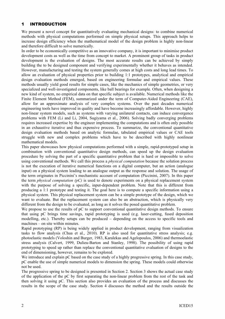
The object of the presented case is a highly progressive rotary spring with high energy density, high torque resistance and minimal sliding motion between the windings. The required progressivity is achieved using a rotational spiral spring with little clearance between the windings. As the spring is wound up, the windings come into contact on an increasing length, thus the stiffness changes. The logarithmic shape and the variable thickness of the spring minimize the friction. Rather than having slipping contact surfaces, the spring gradually winds up from the inside to the outside. The final design of the spring has been manufactured out of metal using waterjet cutting (Figure 1).
Figure 1. Waterjet cut prototype of the final design made of spring steel
The design problem of the case is the quantitative evaluation of a proposed spring shape: The design shall be examined for its rotary stiffness-deflection behaviour and its safe operation. This information is used to judge whether the spring design is fulfils the specified function. The prototype comes at a relatively high cost and several weeks of delivery time; a design evaluation was thus desired prior to ordering the metal spring.
3 APPLICATION CASE
The process of pC is used to complement conventional quantitative design methods in areas where they have weaknesses. The process is as follows: First, the hard to solve part of the design problem has to be identified. Then, a way has to be devised to transfer the respective subproblem to a physical replacement experiment. Often, such a replacement experiment is similar to the original problem. A link that connects a variable, boundary conditions, etc. in the model to a specific measurable characteristic in the physical prototype has to be found. Thereby we can separate the numerical computation from the pC. Ideally the process should be made in a way that it is material independent, thereby simplifying the use of RP. Considering these prerequisites, the pC can then be performed using a physical prototype. Finally, the information from the pC is reintegrated into the previously chosen numerical design method. In the following, the process of the pC is illustrated with the design of a progressive spring. The process of separating the pC from the whole problem is explained using basic formulae from spring design theory (Section 3.1). Based on this knowledge, the pC can be designed and performed (Section 3.2). The information from the pC is then fed into the numerical computation and the stiffness of the spring is estimated (Section 3.3). Finally, the results are discussed in the context of the application, i.e. the spring (Section 3.4). PC can be combined with various quantitative design methods; merely the connection between the numerical model and the physical prototype changes. For the case study, a very simple numerical model is used.
3
ICED15
3.1 Separation In the following, a simple numerical model is derived and the necessary connection to the physical model outlined. The formulae for rotational spiral springs are based on the Euler-Bernoulli beam theory (Wahl, 1944). The stiffness of a spiral spring with no contacts between the windings is given by
𝑘𝑘 = EI 𝑙𝑙⁄ (1)
and its maximum stress is given by
𝜎𝜎𝑀𝑀𝑀𝑀𝑀𝑀 = 12𝑀𝑀 𝑤𝑤𝑡𝑡2⁄ , (2)
where 𝐸𝐸 is Young’s Modulus, 𝐼𝐼 the area moment inertia of the cross-section, 𝑀𝑀 the torque, 𝑤𝑤 the width (out of the plane of the spiral) and 𝑡𝑡 the thickness (in the plane of the spiral) of the spring. For simplicity’s sake, the assumption is made that the thickness, which increases along the spring, is equivalent to putting in series very short springs with accordingly varying cross-sections and an equivalent total length. The resulting stiffness of the 𝑖𝑖-th element is given by
𝜕𝜕𝑘𝑘𝑖𝑖 = 𝐸𝐸𝐼𝐼𝑖𝑖 𝜕𝜕𝑙𝑙𝑖𝑖⁄ (3)
and the total stiffness is given by
𝑘𝑘 = 1 (∑ 1 𝜕𝜕𝑘𝑘𝑖𝑖⁄𝑖𝑖 )⁄ . (4)
These formulae are sufficiently precise for a first design iteration. However they do not take the contact into account. Since the different windings gradually come into contact as the spring is wound up, the length of the contact between windings gradually increases. These parts of the spring cannot be deformed any further and therefore they cannot store any more energy, they are not active anymore. When only considering the active elements of the spring, the resulting the total stiffness is given by
𝑘𝑘 = 1 �∑ 1 𝜕𝜕𝑘𝑘𝑖𝑖⁄𝑖𝑖,𝑀𝑀𝑎𝑎𝑎𝑎𝑖𝑖𝑎𝑎𝑎𝑎 �⁄ . (5)
Because the thickness of the cross-section gradually increases, the maximum stress is located at the transition point between contact and no contact of the windings and is given by
𝜎𝜎𝑀𝑀𝑀𝑀𝑀𝑀 = 12𝑀𝑀 𝑤𝑤𝑡𝑡𝑎𝑎𝑡𝑡𝑀𝑀𝑡𝑡𝑠𝑠𝑖𝑖𝑎𝑎𝑖𝑖𝑠𝑠𝑡𝑡2⁄ . (6)
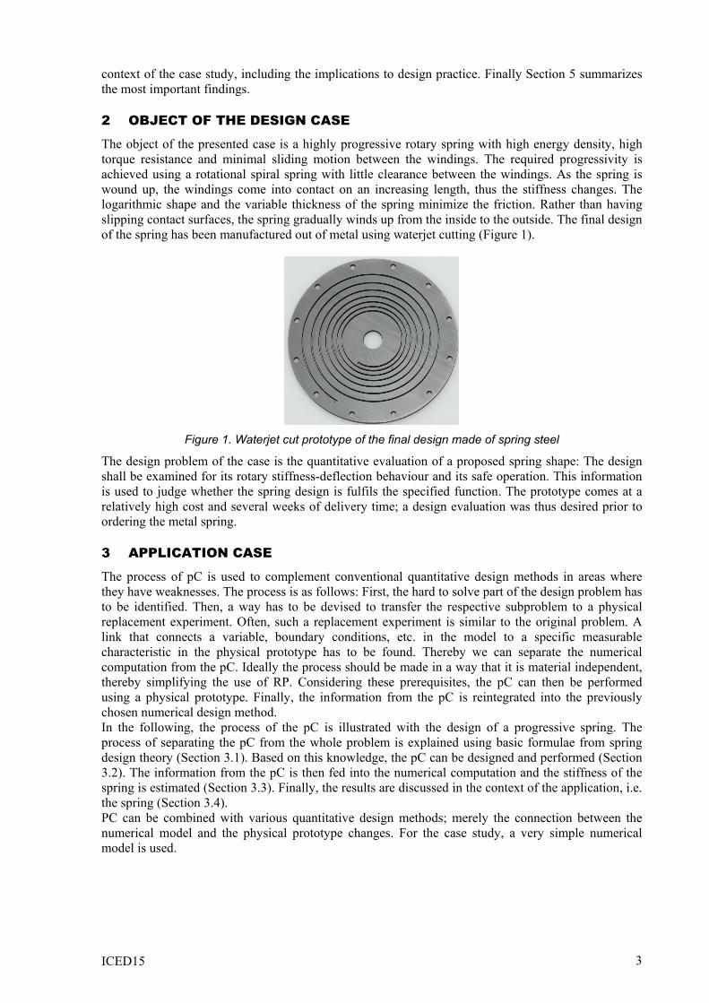
The torque 𝑀𝑀 can be estimated by integrating the stiffness, given by eq. (5) with respect to the deflection angle. The stiffness and the maximum stress at a given deflection angle depend on one variable, the current location of the transition point; this information is found using the pC.
Figure 2. MDF prototype with markings used to estimate the position of the transition point
left: relaxed state, right: deflected state
3.2 Physical computation and simulation The point where the spring transitions from being active to being inactive is found visually on a prototype. The macroscopic deformations of different materials are similar for similar shapes and similar deflection boundary conditions with respect to the shapes, as long as their material behaviour is linear-elastic. Thus a MDF (medium density fibreboard) prototype can be used to find the transition point. This property is called principle of the similarity of deformations in the following (also see Appendix A1). Tagging the transition point while the spring is deflected, allows to subsequently
4
ICED15
measure its position when the spring is relaxed (Figure 2). Thereby the transition point is found as a function of the deflection. Using the data from the pC and eq. (5) we can calculate the stiffness for the shapes tested for a desired deflection. Integrating the stiffness with respect to the deflection yields the torque as a function of the deflection. When the torque is combined with eq. (6), we can estimate the maximum stress for the shapes tested at a given deflection. In the following subsection the precision of the complete procedure is evaluated by assessing the accuracy of the stiffness estimate and showing that maximum stress is not exceeded in the final prototype. While this stress cannot be measured using the test setup, it can be estimated based on the measured torques and the transition point using eq. (6).
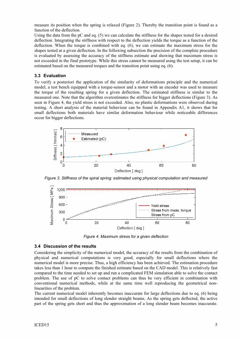
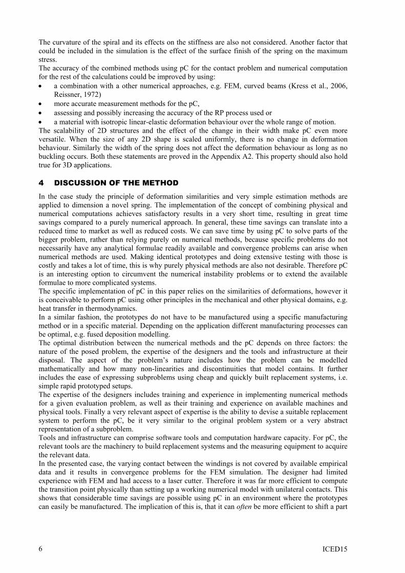
3.3 Evaluation To verify a posteriori the application of the similarity of deformations principle and the numerical model, a test bench equipped with a torque-sensor and a motor with an encoder was used to measure the torque of the resulting spring for a given deflection. The estimated stiffness is similar to the measured one. Note that the algorithm overestimates the stiffness for bigger deflections (Figure 3). As seen in Figure 4, the yield stress is not exceeded. Also, no plastic deformations were observed during testing. A short analysis of the material behaviour can be found in Appendix A1, it shows that for small deflections both materials have similar deformation behaviour while noticeable differences occur for bigger deflections.
Figure 3. Stiffness of the spiral spring: estimated using physical computation and measured
Figure 4. Maximum stress for a given deflection
3.4 Discussion of the results Considering the simplicity of the numerical model, the accuracy of the results from the combination of physical and numerical computations is very good, especially for small deflections where the numerical model is more precise. Thus, a high efficiency has been achieved. The estimation procedure takes less than 1 hour to compute the finished estimate based on the CAD model. This is relatively fast compared to the time needed to set up and run a complicated FEM simulation able to solve the contact problem. The use of pC to solve contact problems can thus be very efficient in combination with conventional numerical methods, while at the same time well reproducing the geometrical non-linearities of the problem. The current numerical model inherently becomes inaccurate for large deflections due to eq. (6) being intended for small deflections of long slender straight beams. As the spring gets deflected, the active part of the spring gets short and thus the approximation of a long slender beam becomes inaccurate.
5
ICED15
The curvature of the spiral and its effects on the stiffness are also not considered. Another factor that could be included in the simulation is the effect of the surface finish of the spring on the maximum stress. The accuracy of the combined methods using pC for the contact problem and numerical computation for the rest of the calculations could be improved by using: • a combination with a other numerical approaches, e.g. FEM, curved beams (Kress et al., 2006,
Reissner, 1972) • more accurate measurement methods for the pC, • assessing and possibly increasing the accuracy of the RP process used or • a material with isotropic linear-elastic deformation behaviour over the whole range of motion. The scalability of 2D structures and the effect of the change in their width make pC even more versatile. When the size of any 2D shape is scaled uniformly, there is no change in deformation behaviour. Similarly the width of the spring does not affect the deformation behaviour as long as no buckling occurs. Both these statements are proved in the Appendix A2. This property should also hold true for 3D applications.
4 DISCUSSION OF THE METHOD
In the case study the principle of deformation similarities and very simple estimation methods are applied to dimension a novel spring. The implementation of the concept of combining physical and numerical computations achieves satisfactory results in a very short time, resulting in great time savings compared to a purely numerical approach. In general, these time savings can translate into a reduced time to market as well as reduced costs. We can save time by using pC to solve parts of the bigger problem, rather than relying purely on numerical methods, because specific problems do not necessarily have any analytical formulae readily available and convergence problems can arise when numerical methods are used. Making identical prototypes and doing extensive testing with those is costly and takes a lot of time, this is why purely physical methods are also not desirable. Therefore pC is an interesting option to circumvent the numerical instability problems or to extend the available formulae to more complicated systems. The specific implementation of pC in this paper relies on the similarities of deformations, however it is conceivable to perform pC using other principles in the mechanical and other physical domains, e.g. heat transfer in thermodynamics. In a similar fashion, the prototypes do not have to be manufactured using a specific manufacturing method or in a specific material. Depending on the application different manufacturing processes can be optimal, e.g. fused deposition modelling. The optimal distribution between the numerical methods and the pC depends on three factors: the nature of the posed problem, the expertise of the designers and the tools and infrastructure at their disposal. The aspect of the problem’s nature includes how the problem can be modelled mathematically and how many non-linearities and discontinuities that model contains. It further includes the ease of expressing subproblems using cheap and quickly built replacement systems, i.e. simple rapid prototyped setups. The expertise of the designers includes training and experience in implementing numerical methods for a given evaluation problem, as well as their training and experience on available machines and physical tools. Finally a very relevant aspect of expertise is the ability to devise a suitable replacement system to perform the pC, be it very similar to the original problem system or a very abstract representation of a subproblem. Tools and infrastructure can comprise software tools and computation hardware capacity. For pC, the relevant tools are the machinery to build replacement systems and the measuring equipment to acquire the relevant data. In the presented case, the varying contact between the windings is not covered by available empirical data and it results in convergence problems for the FEM simulation. The designer had limited experience with FEM and had access to a laser cutter. Therefore it was far more efficient to compute the transition point physically than setting up a working numerical model with unilateral contacts. This shows that considerable time savings are possible using pC in an environment where the prototypes can easily be manufactured. The implication of this is, that it can often be more efficient to shift a part
6
ICED15
of the evaluation problem from the numerical to the physical domain, although there is no simple general rule as to when this is the case.
5 CONCLUSION
We have shown that the transfer of a computational problem from the numerical to the physical domain can significantly accelerate the design process for mechanical structures. For the quantitative evaluation of complicated mechanical structures, numerical methods like FEM are generally efficient. However, when a problem is highly nonlinear, numerical methods often struggle or fail completely to solve the design problem. In this case, the efficiency of the design evaluation process can be increased by combining the numerical methods with pC. This efficiency improvement was demonstrated on a case of the design of a progressive rotary spring. The computation of the spring stiffness is difficult in this case because of a variable contact that leads to a highly non-linear mathematical model. The approach to separate the problem and solve one subproblem physically with a replacement system based on a cheap rapid prototype and the other subproblem numerically, proved to be fast and accurate, hence efficient. From this case-study, we can deduce that when a mathematical problem is highly non-linear, and therefore demanding to solve numerically, the problem has a high potential to be solved more efficiently by combining numerical methods with pC. Due to the large diversity of design problems, a global rule for the right combination of numerical and pC can probably not be formulated. An engineering designer shall be guided in this question by the criterion of efficiency. The more linear subproblems are, the more efficiently they are solved numerically. The more non-linearities and discontinuities they contain, the more the advantages are predominant in the physical domain. The optimal choice between using numerical or pC to solve a single subproblem depends on three factors: the mathematical nature of the subproblem, the expertise of the designer and the available digital and physical tools.
REFERENCES CALVERT, G. 1999. Developments in rapid thermoelastic analysis. Strain, 35, 67-71. CHUA, C. K., LEONG, K. F. & LIM, C. S. 2010. Rapid prototyping: principles and applications, World
Scientific. DULIEU-BARTON, J. & STANLEY, P. 1998. Development and applications of thermoelastic stress analysis.
The Journal of Strain Analysis for Engineering Design, 33, 93-104. KARALEKAS, D. E. & AGELOPOULOS, A. 2006. On the use of stereolithography built photoelastic models
for stress analysis investigations. Materials & Design, 27, 100-106. KRESS, G., SAUTER, M. & ERMANNI, P. 2006. Complex-shaped beam finite element. Finite Elements in
Analysis and Design, 43, 112-126. LI, W. & LI, Q. 2004. A contact finite element algorithm for the multileaf spring of vehicle suspension systems.
Proceedings of the Institution of Mechanical Engineers, Part D: Journal of Automobile Engineering, 218, 305-314.
PICCININI, G. 2007. Computing Mechanisms. Philosophy of Science, 74, 501-526. REISSNER, E. 1972. On one-dimensional finite-strain beam theory: the plane problem. Zeitschrift für
angewandte Mathematik und Physik ZAMP, 23, 795-804. SUGIYAMA, H., SHABANA, A. A., OMAR, M. A. & LOH, W.-Y. 2006. Development of nonlinear elastic
leaf spring model for multibody vehicle systems. Computer Methods in Applied Mechanics and Engineering, 195, 6925-6941.
VOLOSHIN, A. & BURGER, C. 1983. Half-fringe photoelasticity: a new approach to whole-field stress analysis. Experimental Mechanics, 23, 304-313.
WAHL, A. M. 1944. Mechanical springs, Penton Publishing Company.
ACKNOWLEDGMENTS This work was supported by ETH Research Grant ETH-22 13-2.
APPENDIX A1: MATERIAL-INDEPENDENCE The use of RP is a key point to make pC fast. The pC setup generally will be made of a different material than the final product. In order enable the use of different materials, they have to deform identically when subjected to the operating conditions.
7
ICED15
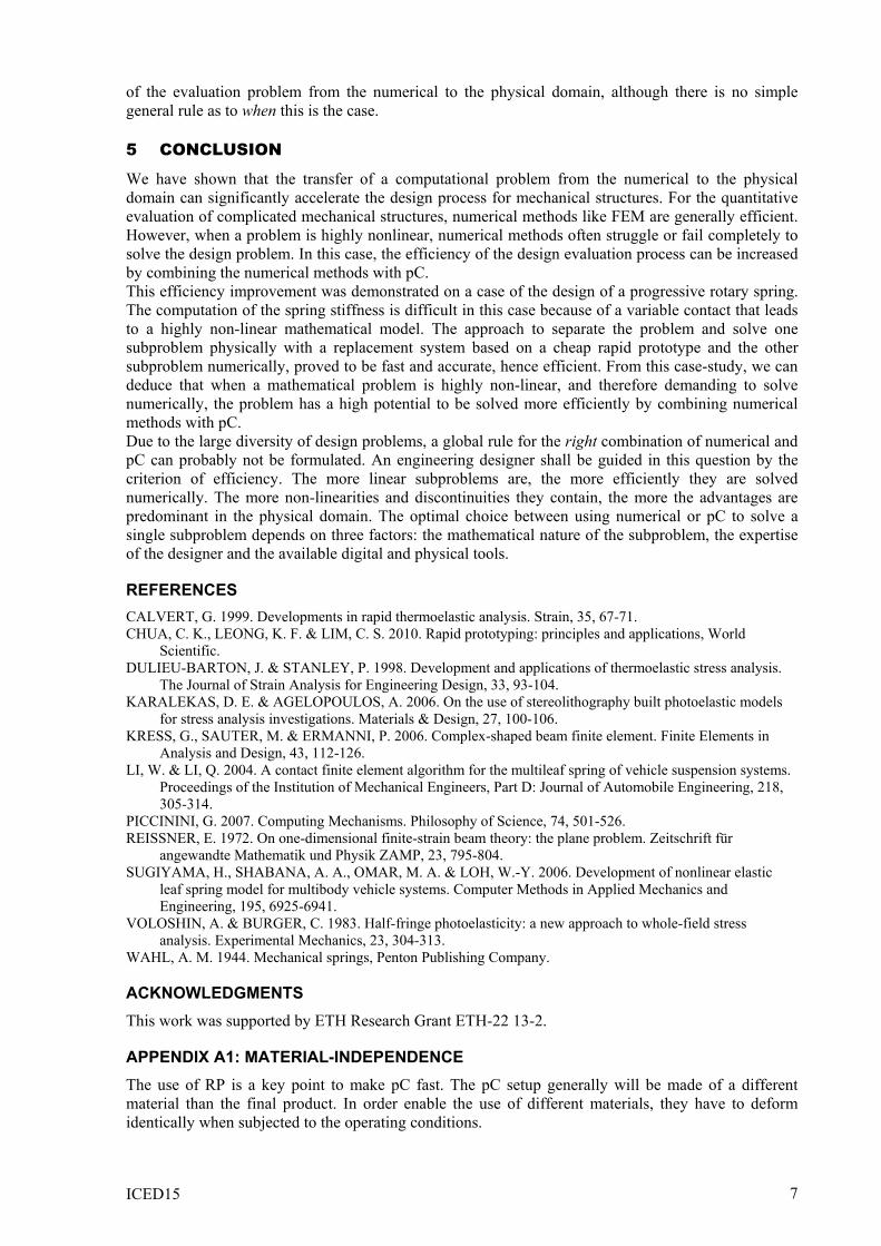
Metals are considered to have anisotropic linear elastic behaviour when subjected to loads, as long as the maximum stress is below the yield stress. The spring should not be damaged from the loading, thus linear elastic behaviour can be assumed. Therefore, the MDF should also exhibit anisotropic linear elastic deformations. The material properties of the specific MDF used are not documented. The active length of both prototypes is nearly identical when the prototypes are deflected in the range where contact transition point is easy to find (Figure 5). For bigger deflections there is noticeable differences in the deformation behaviour (Figure 6).
Figure 5. Comparison of the active length for the wooden and metal springs
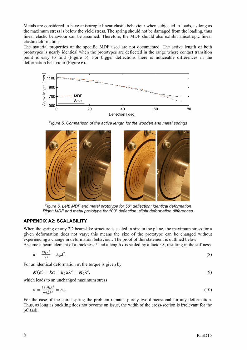
Figure 6. Left: MDF and metal prototype for 50° deflection: identical deformation
Right: MDF and metal prototype for 100° deflection: slight deformation differences
APPENDIX A2: SCALABILITY When the spring or any 2D beam-like structure is scaled in size in the plane, the maximum stress for a given deformation does not vary; this means the size of the prototype can be changed without experiencing a change in deformation behaviour. The proof of this statement is outlined below. Assume a beam element of a thickness 𝑡𝑡 and a length 𝑙𝑙 is scaled by a factor 𝜆𝜆, resulting in the stiffness
𝑘𝑘 = 𝐸𝐸𝐼𝐼0𝜆𝜆3
𝑙𝑙𝑜𝑜𝜆𝜆= 𝑘𝑘0𝜆𝜆2. (8)
For an identical deformation 𝛼𝛼, the torque is given by
𝑀𝑀(𝛼𝛼) = 𝑘𝑘𝛼𝛼 = 𝑘𝑘0𝛼𝛼𝜆𝜆2 = 𝑀𝑀0𝜆𝜆2, (9)
which leads to an unchanged maximum stress
𝜎𝜎 = 12 𝑀𝑀0𝜆𝜆2
𝑤𝑤𝑎𝑎02𝜆𝜆2= 𝜎𝜎0. (10)
For the case of the spiral spring the problem remains purely two-dimensional for any deformation. Thus, as long as buckling does not become an issue, the width of the cross-section is irrelevant for the pC task.
8