
Effective solution for AC power calibration · Effective solution for AC power calibration. ......
12
Bulletin LS3300-01EN LS3300 AC power calibrator Effective solution for AC power calibration
-
Upload
trinhkhuong -
Category
Documents
-
view
218 -
download
0
Transcript of Effective solution for AC power calibration · Effective solution for AC power calibration. ......

Bulletin LS3300-01EN
LS3300AC power calibrator
Effective solution for AC power calibration

2Introduction to broad industrial fields
The LS3300 provides:
Technology – The LS3300 delivers best-in-class power accuracy of 100 ppm and high output current of 62.5 A.
Confidence – Yokogawa’s attention to quality ensures engineers have the peace of mind knowing that the LS3300 is designed to meet the high stability and accuracy needed for testing power meters.
Operability – Combining flexibility of single to three phase calibration and a suite of features for power meter validation, The LS3300 is an excellent choice for efficient, expeditious calibration.
Yokogawa has been supplying precision measuring instruments of the highest quality for over 100 years.
Power meters and measuring instruments much adhere to strict standards to not only make precise voltage and current measurements, but to reliably and accurately calculate power and phase. Thus, calibration of these instruments to maintain integrity and lifespan is of utmost importance to the test and measurement industry. It is with this in mind that Yokogawa is proud to release its latest high precision power calibrator, the LS3300.
Introduction to broad industrial fields
Major instruments subject to calibration
Clamp-on power meter Power monitor
Power transducer
AC clamp-on tester Portable Analog Instruments (W, V, A, PF, etc)
Power meter of 0.2% class(commercial frequency)
Power meter of 0.15% class (commercial frequency)
Accredited calibration laboratories and private calibration companies
Companies that manufacture measurement instruments.
Calibration divisions of companies that manufacture industrial equipment such as office electronics, home appliances, automobiles, motors, etc.

LS3300
1 LO TO EARTH LAMP (voltage)
2 LO TO EARTH LAMP (current)
3 HIGH VOLTAGE LAMP
4 Current output terminals
5 Voltage output terminals
6 AUX output terminal
7 OUTPUT ON/OFF key
8 Output select key
9 Output terminals for synchronized operation
10 Input terminals for synchrenized operation
11 Functional ground
12 USB port
13 Ethernet port
14 GP-IB connector
15 Link interface (UNIT2/UNIT3)
3 Introduction to broad industrial fields
Major SpecificationsThe LS3300 is a single-phase AC power calibrator that can generate highly accurate, stable, and wide range output current and voltage. New features include an LCD display and a “STABILIZING function” which shows that the output signal is stabilized for calibration efficiency.
Front/rear
High accuracyAC voltage: ±350 ppmAC current: ±450 ppmAC power: ±450 ppmAt 1 year, 10 ppm = 0.001%
High stabilityAC voltage, current: ±50 ppm/hAC power: ±100 ppm/hFrom 1 minute to 1 hour after the output is turned on.
Phase accuracy±0.03˚ at 50/60 HzBetween the Voltage and current outputs when used alone.
Wide generation rangeAC voltage: 10 mV to 1250 VAC current: 0.3 mA to 62.5 AFrequency: 40 to 1200 Hz
13
11
12 15
14
10 9
8
7 3
54
61
2

LS3300 4Major Features
Single to three phase power calibration
A single LS3300 unit supports 1P2W, and multiple LS3300 units support 1P3W, 3P3W and 3P4W. It can calibrate AC voltage/current, active/reactive power, power factor and phase angle.
Control and output of three phase power
Multiple LS3300 units can be synchronized through BNC cables. The host can then connect to the master unit via a USB cable and adjust the settings on all units through the master/slave communication. Users can set the values of voltage, current, power, power factor, wiring, and phase from the front panel of the master unit and view each phase in a phase chart in the LCD. Checking the output of each unit from the master unit during three-phase output is done by navigating to [CONFIG] > [Unit] key > menu.
When changing the wiring from 3P3W (three voltages threecurrents) or 3P4W to 1P3W or 3P3W, users can selectfrom among T phase reference using UNIT2 and S phasereference using UNIT3. The LS3300 supports both references because the reference differs depending on each power meter. They can use either phase reference by setting it on the master unit as needed.
(1) When outputting balanced three-phaseIn the case of balanced phase signals, when users modify settings on the master unit, values on the slave units are set accordingly. Synchronous communication allows output setting changes on the master unit to be migrated to the slave unit. If a fault such as an overload occurs in the slave unit, this information will be conveyed to the master unit, then initiate a shutdown of output.
(2) When outputting unbalanced three-phase signalsIn the case of unbalanced phase signals, users set the conditions of a balanced state for the slave units on the master unit. Then they change the phase setting into single phase and manually set conditions of the unbalanced phase state of each phase of the slave side.
On-Site calibration service
Other power calibration systems in the market utilize a master/slave interface where-in the slave units cannot be operated standalone for single phase output. Each LS3300, on the other hand, is capable of both independent single phase output, as well as synchronized three phase output. Its excellent portability enables feasible on- site calibration service.
Major Features
Wiring system setting
Example of 3P3W (three voltage three current) /3P4W
Current value setting
Example of 1P3W and 3P3W
HI
LO HI
LO ±
I
± U
HI
LO HI
LO ±
I
± U VOLTAGEVOLTAGE
LS3300UNIT1
LS3300UNIT2
CURRENT
Power meterElement2
V/ ILo to Earth
Wiring when calibrating power
Power meterElement1
Master
Slave 後送
LS3300
LS3300
Master
Slave
Slave
HI
LO HI
LO ±
I
± U
HI
LO HI
LO ±
I
± U
HI
LO HI
LO ±
I
± U
CURRENT
Wiring when calibrating power
VOLTAGE
V/ILo to Earth
LS3300UNIT1
LS3300UNIT2
Power meterElement2
Power meterElement1
LS3300UNIT3
Power meterElement3
LS3300
LS3300
LS3300

LS33005 Major Features
Large current output up to 180 A
When users synchronize three units and connect their output in parallel, the system can output up to 180 A, when [Hi Current] is specified in the Wiring menu. LS3300 supports devices requiring large current such as a current sensor, smart meter, etc.
Diversification of the calibration equipment by AUX output
A large current sensor used for industrial equipment and a clamp-on power meter used to monitor energy-saving are widely used in the power measurement market. When a clamp-on power meter unit or external current sensor input (voltage output) is calibrated, an AUX terminal is used. The voltage output range of a current sensor signal (Ext. Sensor) is 0 to 6.25 V.Users can select either the 500 mV or 5 V range according to the output range of a current sensor.
LCD for enhanced viewing capabilities
The LS3300 is equipped with a 5.7-inch color LCD. It shows the wiring and power settings, as well as the phase chart of the generated waveforms, allowing users to quickly and easily view the instrument settings (as seen below). Users are also be able to view the unit information such as the serial number, version information, and communication settings in the UTILITY menu. The values of voltage, current, active power and reactive power specified according to the level, level ration and power factor are displayed as output values.
Phase wire settings screen
Phase chart*Zooming the Phase chart
Output settings screen
La
rge c
urre
nt
Shunt resistor
Converter
Smart meter
Current sensor
Clamp-on tester
LS3300
LS3300
LS3300
AUX TerminalExample: CW500
Current sensor inputof clamp-on power meter
VoltageVoltage
Example: WT310ECalibration of external current sensor’s input terminal
LS3300
TYPE-1 TYPE-2
*There are two types of Phase chart:TYPE1: Phase 0° (reference signal phase) points to the right.TYPE2: Phase 0° (reference signal phase) points up.
1P2W 3P3W (3V3A)(S phase reference)
1P2W(1P2W Hi current)
3P3W (3V3A)(S phase reference)
0
V2
V1
I3
I2
V3
I10V1
I1
0
I1
I2
I3
V3
V2
V1
0
V1I1
LS3300 6Applications
Input
Output
Transducer
DMM
LS3300
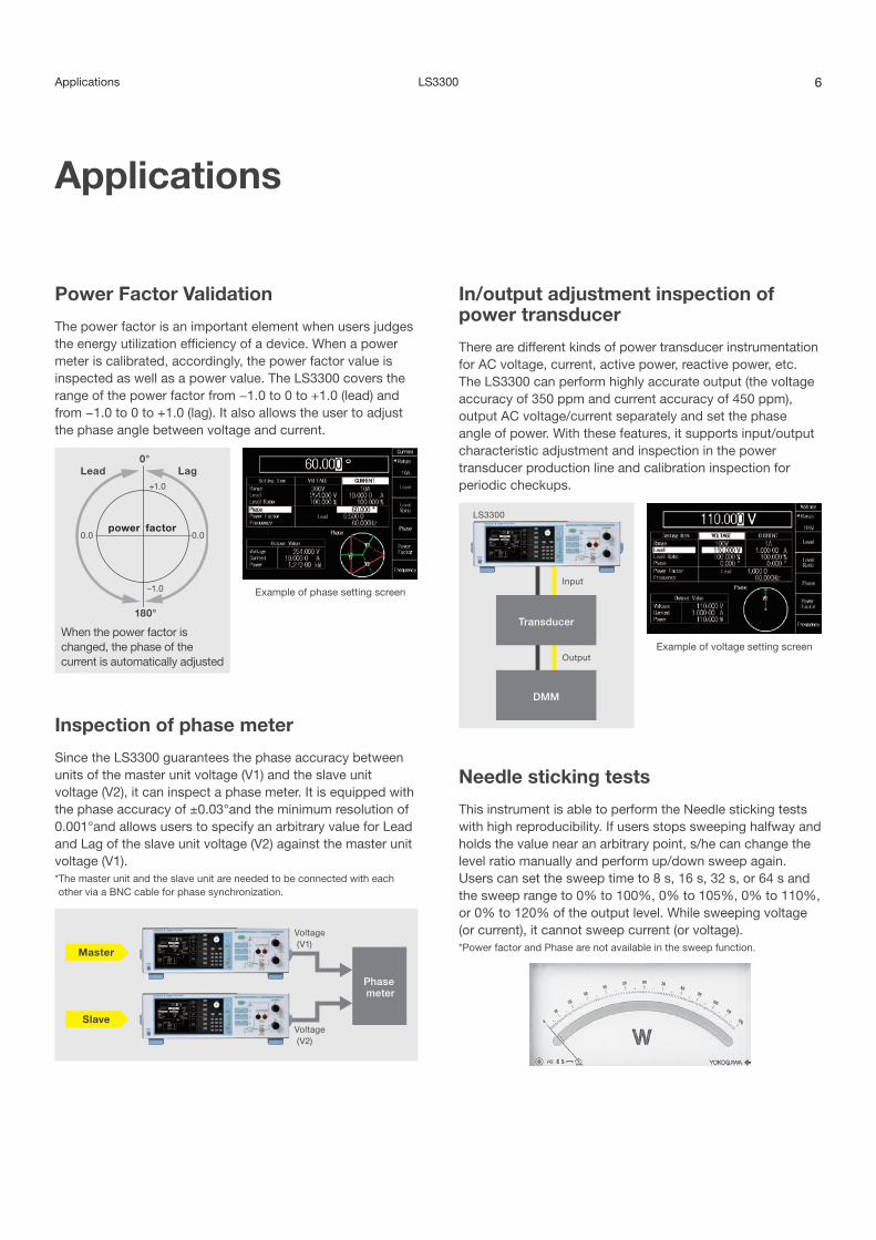
Power Factor Validation
The power factor is an important element when users judges the energy utilization efficiency of a device. When a power meter is calibrated, accordingly, the power factor value is inspected as well as a power value. The LS3300 covers the range of the power factor from −1.0 to 0 to +1.0 (lead) and from −1.0 to 0 to +1.0 (lag). It also allows the user to adjust the phase angle between voltage and current.
In/output adjustment inspection of power transducer
There are different kinds of power transducer instrumentation for AC voltage, current, active power, reactive power, etc. The LS3300 can perform highly accurate output (the voltage accuracy of 350 ppm and current accuracy of 450 ppm), output AC voltage/current separately and set the phase angle of power. With these features, it supports input/output characteristic adjustment and inspection in the power transducer production line and calibration inspection for periodic checkups.
Needle sticking tests
This instrument is able to perform the Needle sticking tests with high reproducibility. If users stops sweeping halfway and holds the value near an arbitrary point, s/he can change the level ratio manually and perform up/down sweep again.Users can set the sweep time to 8 s, 16 s, 32 s, or 64 s and the sweep range to 0% to 100%, 0% to 105%, 0% to 110%, or 0% to 120% of the output level. While sweeping voltage (or current), it cannot sweep current (or voltage).* Power factor and Phase are not available in the sweep function.
Inspection of phase meter
Since the LS3300 guarantees the phase accuracy between units of the master unit voltage (V1) and the slave unit voltage (V2), it can inspect a phase meter. It is equipped with the phase accuracy of ±0.03°and the minimum resolution of 0.001°and allows users to specify an arbitrary value for Lead and Lag of the slave unit voltage (V2) against the master unit voltage (V1).* The master unit and the slave unit are needed to be connected with each other via a BNC cable for phase synchronization.
power factor
LagLead
−1.0
0.0 0.0
+1.0
0°
180°
When the power factor is changed, the phase of the current is automatically adjusted
Example of phase setting screen
Applications
Example of voltage setting screen
Master
Slave
Voltage (V1)
Voltage (V2)
Phase meter

LS33007 Convenient features for calibration
Shortening of calibration time
(1) Notification that output becomes stableTo improve working efficiency, the LS3300 is equipped with afunction for notifying the user that the output is stable. When the STABILIZING indication disappears from the LCD two seconds later, it means that the output has become stable. This reduces time spent on working with transient signals that affect measurement accuracy.
Safety of calibration
(1) High voltage notificationThis is a function for notifying users of dangerous high voltage condition when the high voltage range (300 or 1000 V) is set. When the voltage output is set to 150 V or higher, the device beeps intermittently.
(2) Trip detectionIf a load that would cause the output range to be exceeded is connected, this instrument detects the abnormal load to protect itself. This function monitors the error of overcurrent and overvoltage, oscillation, fan malfunction and temparature.
(3) LINE synchronizationThe output frequency of this product can be synchronized with commercial power frequency. This feature is useful in checking interference from the power source.
Communication interface
The LS3300 is fitted with USB, Ethernet and GP-IB as standard communication interface to control external devices remotely.
For example: Remote control from a PC automates calibration
Sample program will be released soon
We will provide a free sample program and driver for each communication interface (USB, Ethernet and GP-IB) in our web site for the convenience of users.
LabVIEW measuring instrument driver will be released soon
We will provide a free measuring instrument driver for creating a LabVIEW program on our website for the convenience of users.* LabVIEW is a registered trademark of National Instruments Corporation in the U.S.A.
Convenient features for calibration
For example: WT310E
LS3300 PCSetting calibration point
Acquiring measure-ment
values
Self-made software
Data �le output
Reduction of calibration time
Supplying power
“STABILIZING” indication during output
High voltage setting screen

LS3300 8Basic characteristic examples showing high accuracy and stability
Comparison table to the 2558A (1 year)
Basic characteristic examples showing high accuracy and stability
−600.0
−500.0
−400.0
−300.0
−200.0
−100.0
0.0
100.0
200.0
300.0
400.0
500.0
600.0
0% 20% 40% 60% 80% 100% 120%
Err
or [p
pm
] of R
ange
Setting
100 V/10 A
SPEC (+)
SPEC (−)
1 kW Range (1% to 120%; PF = 1)
−100.0
−80.0
−60.0
−40.0
−20.0
0.0
20.0
40.0
60.0
80.0
100.0
0 600 1200 1800 2400 3000 3600
Time [sec]
Err
or [p
pm
] of R
ange
1 kW Range (100 V/10 A, PF = 1)
−1400
−1200
−1000
−800
−600
−400
−200
0
200
400
600
800
1000
1200
1400
10 100 1000
Frequency [Hz]E
rror
[pp
m] o
f Ran
ge
100 V/10 A
SPEC (+)
SPEC (−)
1 kW Range (40 to 1200 Hz)
−0.030
−0.020
−0.010
0.000
0.010
0.020
0.030
0 600 1200 1800 2400 3000 3600
100 V/10 A PF = 0 (LAG)
Pha
se E
rror
[deg
]
Time [sec]
Example of Power linearity characteristic
Example of Power stability characteristic
Example of Frequency - Power accuracy characteristic
Example of Phase stability characteristic
LS3300 2558A
AC voltageGuaranteed accuracy range 10 mV to 1250 V 1.00 mV to 1200.0 VAccuracy 50/60 Hz ±350 ppm ±500 ppm
AC currentGuaranteed accuracy range 0.3 mA to 62.5 A 1.00 mA to 60.0 AAccuracy 50/60 Hz ±450 ppm ±650 ppm
FrequencyOutput range 40 to 1200 Hz 40 to 1000 HzAccuracy ±100 ppm ±100 ppm
AC powerGuaranteed accuracy range
Range of voltage, current and frequency mentioned above
N/A
Accuracy 50/60 Hz ±450 ppm N/APower stability ±100 ppm N/APower factor (Lead/Lag) −1 to 0 to 1 N/APhase angle −180.000° to 359.999° N/AMaximum output Approx. 36 VA Approx. 36 VADimentions (mm) 426 (W) × 132 (H) × 450 (D) 426 (W) × 132 (H) × 400 (D)

LS3300
Output Range
AC VoltageRange Output Range *1 Resolution Maximum Output Output Resistance *2
1 V 0 to ± 1.25000 V 10 µV 0.5 A or more 6 mΩ or less10 V 0 to ± 12.5000 V 100 µV Approx. 600 mA 6 mΩ or less30 V 0 to ± 37.5000 V 100 µV Approx. 60 mA 6 mΩ or less
100 V 0 to ± 125.000 V 1 mV Approx. 60 mA 6 mΩ or less300 V 0 to ± 375.000 V 1 mV Approx. 20 mA 6 mΩ or less
1000 V 0 to ±1250.00 V 10 mV Approx. 6 mA 6 mΩ or less
AC CurrentRange Output Range *1 Resolution Maximum Output30 mA 0 to ± 37.5000 mA 0.1 µA Approx. 15 V
100 mA 0 to ±125.000 mA 1 µA Approx. 15 V1 A 0 to ± 1.25000 A 10 µA Approx. 15 V
10 A 0 to ± 12.5000 A 100 µA Approx. 3 V50 A 0 to ± 62.500 A 1 mA Approx. 0.6 V
AUXRange Output Range *1 Resolution Maximum Output Output Resistance
500 mV 0 to ±625.00 mV 10 µV Approx. 0.1 mA 1 Ω or less5 V 0 to ± 6.2500 V 100 µV Approx. 5 mA 1 Ω or less
*1: The output level can be set up to 120% of the range. For outputs exceeding 120%, the ratio must be set to 100% or higher.*2: When 758933, 758917, or B8506ZK is in use; excluding aging and the effects of measurement leads
AccuracyConditions Frequency: Using the internal oscillator
Load: Pure resistanceTemperature, humidity: 23°C ±3°C, 20% RH to 80% RHWhen the temperature is in the range of 5°C to 20°C or 26°C to 40°C, add the temperature coefficient.Output terminals: LO terminal groundingMeasurement bandwidth: Up to 50 kHz
AC Voltage
Range Display Resolution
Accuracy (1 year), ±(% of Setting + % of Range)
10% to 125% of range *1 1% to 10% of range *1, *2
50/60 Hz 40 Hz ≤ f ≤ 400 Hz *2 400 Hz < f ≤ 1.2 kHz 50/60 Hz 40 Hz ≤ f ≤ 400 Hz 400 Hz < f ≤ 1.2 kHz1 V 10 µV
0.03 + 0.005 0.05 + 0.01 0.10 + 0.02 0.008 0.015 0.03
10 V 100 µV30 V 100 µV
100 V 1 mV300 V 1 mV
1000 V 10 mV
AC Current
Range Display Resolution
Accuracy (1 year), ±(% of Setting + % of Range)10% to 125% of range 1% to 10% of range
50/60 Hz 40 Hz ≤ f ≤ 400 Hz *2 400 Hz < f ≤ 1.2 kHz 50/60 Hz 40 Hz ≤ f ≤ 400 Hz *2 400 Hz < f ≤ 1.2 kHz30 mA 0.1 µA
0.04 + 0.005 0.06 + 0.01 0.12 + 0.02 0.009 0.016 0.032100 mA 1 µA
1 A 10 µA10 A 100 µA50 A 1 mA
AUX
Range Display Resolution
Accuracy (1 year), ±(% of Setting + % of Range)10% to 125% of range *1 1% to 10% of range *1
50/60 Hz 40 Hz ≤ f ≤ 400 Hz *2 400 Hz < f ≤ 1.2 kHz 50/60 Hz 40 Hz ≤ f ≤ 400 Hz *2 400 Hz < f ≤ 1.2 kHz500 mV 10 µV
0.04 + 0.01 0.06 + 0.01 0.12 + 0.02 0.014 0.016 0.0325 V 100 µV
*1: Excludes voltage drop due to the output resistance*2: Includes the accuracy specification at LINE synchronization setting. However, there are no fluctuation in frequency and duty in LINE.
9 Specifications
Specifications

LS3300
Active Power (Watt)
Output rangeAccuracy (1 year)
±{(% of VA) × PF + % of range + PWRerror (% of VA)} *3, *4, *5 ±{% of range + PWRerror (% of VA)} *3, *4, *5
10% to 125% of range 1% to 10% of rangeFrequency range 50/60 Hz 40 Hz ≤ f ≤ 400 Hz *6 400 Hz < f ≤ 1.2 kHz 50/60 Hz 40 Hz ≤ f ≤ 400 Hz *6 400 Hz < f ≤ 1.2 kHz
Accuracy 0.040 + 0.005 + PWRerror
0.060 + 0.010 + PWRerror
0.120 + 0.020 + PWRerror
0.009 + PWRerror
0.016 + PWRerror
0.032 + PWRerror
*3: For phase setting Ø, power factor PF = cosØ Equation for calculating the value to add to the active power accuracy for the phase error (ΔØ)
PWRerror (%) = 100 × {cosØ – cos (Ø + ΔØ)} Example: For 60 Hz, phase Ø = 60°, ΔØ = +0.03°
PWRerror (%) = 100 × {cos (60) – cos (60.03)} = 0.0453% *4: Add 0.005% of range for AUX output. *5: The output range that the power accuracy applies to is for when the voltage and current (including AUX) are at least 1% of the range. *6: Includes the accuracy specification when LINE synchronization is set. However, no fluctuation in the LINE frequency or duty ratio is assumed.
Reactive Power (VAR)
Output rangeAccuracy (1 year)
±{(% of VA) × PF + % of range + VARerror (% of VA)} *7, *8, *9 ±{% of range + VARerror (% of VA)} *7, *8, *9
10% to 125% of range 1% to 10% of rangeFrequency range 50/60 Hz 40 Hz ≤ f ≤ 400 Hz *10 400 Hz < f ≤ 1.2 kHz 50/60 Hz 40 Hz ≤ f ≤ 400 Hz *10 400 Hz < f ≤ 1.2 kHz
Accuracy 0.040 + 0.005 + VARerror
0.060 + 0.010 + VARerror
0.120 + 0.020 + VARerror
0.009 + VARerror
0.016 + VARerror
0.032 + VARerror
*7: For phase setting Ø, power factor PF = sinØ Equation for calculating the value to add to the reactive power accuracy for the phase error (ΔØ)
VARerror (%) = 100 × {sinØ – sin (Ø + ΔØ)}Example: For 60 Hz, phase Ø = 60°, ΔØ = +0.03°
VARerror (%) = 100 × {sin (60) – sin (60.03)} = −0.0262%*8: Add 0.005% of range for AUX output.*9: The output range that the power accuracy applies to is for when the voltage and current (including AUX) are at least 1% of the range.*10: Includes the accuracy specification when LINE synchronization is set. However, no fluctuation in the LINE frequency or duty ratio is assumed.
Phase (between the voltage and current outputs when used alone or between the voltage outputs of the master and slave devices when linked)
Accuracy (1 year)Frequency range 50/60 Hz 40 Hz ≤ f ≤ 400 Hz *12 400 Hz < f ≤ 1.2 kHz
Current output (I1) corresponding to voltage (V1) or between the voltage outputs of the master and slave devices when linked *11 ±0.03° ±0.10° ±0.40°
AUX output (I1) corresponding to voltage (V1) *11 ±0.05° ±0.10° ±0.40°Slave voltage (V2) corresponding to master voltage (V1) *11 ±0.03° ±0.10° ±0.40°*11: The output level can be set 10% to 125% of the range.*12: Includes the accuracy specification at LINE synchronization setting. However, there are no fluctuation in frequency and duty in LINE.
Frequency Accuracy (1 year): ±100 ppm
Stability
Conditions Output range: 1% to 125% of rangeOutput state: The same output state is retained (no load fluctuation).Frequency: Using the internal oscillator. Add 50 ppm of range for 1 kHz to 1.2 kHz.Output terminals: LO terminal groundingTemperature, humidity: 23°C ±3°C, 20% RH to 80% RH, no fluctuationOther conditions: No fluctuation (such as wind)Time: From 1 minute to 1 hour after the output is turned on
Item ±(ppm of Setting + ppm of Range)
Voltage 20 + 30
Current 20 + 30
Power (PF = 1) 40 + 60
Temperature coefficient
Item Specifications
Voltage output/Current output/AUX output
50/60 Hz ±30 ppm/°C of setting, at 5°C to 20°C and 26°C to 40°C
Other frequencies 40 Hz to 1.2 kHz *1
±50 ppm/°C of setting, at 5°C to 20°C and 26°C to 40°C
Phase 50/60 Hz ±0.001°/°C, at 5°C to 20°C and 26°C to 40°C
Other frequencies 40 Hz to 1.2 kHz *1
±0.002°/°C, at 5°C to 20°C and 26°C to 40°C
*1: Includes the accuracy specification when LINE synchronization is set.
Response Time
Item Specifications
Voltage/current/ AUX output
Approx. 2 sec, at 0 -> 100% of the setting (until the output converges to 0.02% of the last value)
Distortion Rate
Conditions Frequency range: 40 Hz to 1.2 kHzRoad: Pure resistanceThe load current during voltage generation and the load voltage during current generation are less than or equal to 20% of the maximum output.Output range: 40% to 125% of range
Item Specifications
Voltage output 0.07% or smaller
Current output 0.18% or smaller
AUX output 0.10% or smaller
Other specification
10Specifications

LS3300
Settings and Display Items
Setting
Items Setting Value Resolution
Voltage Range 1 V, 10 V, 30 V, 100 V, 300 V, 1000 V
Refer to “Output Range”
Level 0 to 120% (of range)
Level Ratio 0 to 120% (of setting) *1 0.001%
Phase Angle −180° to +359.999° 0.001°
Current Range 30 mA, 100 mA, 1 A, 10 A, 50 A, 100 A *2, 150 A *2
AUX Output 500 mV, 5 V
1P2W (HI Current) *2
Level 0 to 120% (of range)
Level Ratio 0 to 120% (of setting) *1 0.001%
Phase Angle −180° to +359.999 0.001°
Power Factor LEAD/LAG −1 to 0 to +1 0.0001
Frequency 40 Hz to 1.2 kHz 0.001 Hz
Wiring *2 kind of wiring 1P2W, 1P2W (Hi Current) *2, 1P3W, 3P3W, 3P3W (3V3A), 3P4W
Oscillator INTernal 40 Hz to 1.2 kHz 0.001 Hz
EXTernal Input from the external oscillator (I/Q)
Refer to “Explanation of External Input”
LINE 50/60 Hz 0.001°
Sweep Time 8 s, 16 s, 32 s, 64 s
Range *3 0 to 100%, 0 to 105%, 0 to 110%, 0 to 120%
AUX V/A Convertion Ration *4
0.0001 mV/A to 99999.9999 mV/A
0.0001 mV/A
Ground/Ungrounded *5 Voltage and current (including AUX) can be switched separately.
*1: The output value is determined by “level × level ratio”, but the maximum output is 125% of range.
*2: When synchronous operation is in use and the master wiring is not 1P2W, all the items above are set on the master side.
The 100 A range that becomes available using 1P2W (HI current) can be output with two units. The accuracy specification twice that of the 50 A range. The 150 A range can be output with three units. The accuracy specification three times that of the 50 A range. *3: The sweep range (%) indicates the level ratio range. *4: Default value; 1000 mV/A *5: When the Lo terminal is grounded, voltage cannot be applied between Lo and ground.
Display *1
Item Display
Voltage (Vout) Output level Level setting × Ratio setting
Current (Iout) Output level Level setting × Ratio setting
Phase *2 Displays the output phase setting relative to the reference signal
Power Factor (PF) *3 Displays the power factor equivalent to the current phase relative to the voltage
Active Power (W) Displays the power calculated from active power (W) Vout × Iout × cosØ or Vout × Iout × PF.
Reactive Power (var) Vout × Iout × sinØ
*1: All output displays show values derived from the above equations.*2: If the wiring is 1P2W, the voltage and current phases can be set separately. For other wiring systems, set the current phase relative to the voltage. The phase is positive when the current leads the voltage. *3: LEAD indicates that the current phase is leading the voltage. LAG indicates that the current
phase is lagging the voltage.
External Input and Output
Master/Slave Synchronous Operation Input and Output (Two terminals each; four terminals total)
Item Specifications
Input/output voltage 3 V ± 0.1 Vrms, sine wave
Frequency range 40 Hz to 1.2 kHz
Input resistance Approx. 1 MΩ
Output resistance Approx. 50 Ω
TerminalFrequency selection
Internal oscillator EXT *1 LINE
(50 Hz to 60 Hz) *2, *3
Input cos (I) Not used Used Not used
sin (Q) Not used Used Not used
Output cos (I) Internal cos (I) signal
Connected to input terminal cos (I)
Internal cos (I) signal
sin (Q) Internal sin (Q) signal
Connected to input terminal sin (Q)
Internal sin (Q) signal
*1: Phase difference between I and Q: Within 90°±0.1°*2: If the commercial power frequency is less than 45 Hz or greater than 65 Hz, the instrument
generates an error and cannot produce output.*3: If the duty ratio exceeds 50 ±5%, the instrument generates an error and cannot produce
output.
Computer Interface
USB for PC ConnectionConnector type Type B connector (receptacle)
Electrical and mechanical Complies with USB Rev. 2.0
Supported transfer modes HS (High Speed; 480 Mbps) and FS (Full Speed; 12 Mbps)
Supported protocols USBTMC-USB488 (USB Test and Measurement Class Ver.1.0)
EthernetConnector type RJ-45 connector
Electrical and mechanical Conforms to IEEE 802.3
Transmission system 100 BASE-TX/10 BASE-T
Transfer rate 100 Mbps max.
Supported services VXI-11, DHCP
GP-IBElectrical and mechanical Complies with IEEE St’d 488-1978
Functional specifications SH1, AH1, T5, L4, SR1, RL1, PP0, DC1, DT1, C0
Protocol Complies with IEEE St’d 488.2-1992
Address 0 to 30
Connecting interfaceConnector type Type B connector (receptacle)
Electrical and mechanical Equivalent to USB Rev. 2.0
Supported system environment
Valid only for the connection between the master and slave LS3300
General Specifications
Item Specifications
Warm-up time Approx. 30 minutes
Operating environment Temperature: 5°C to 40°C
Humidity: 20% RH to 80% RH (no condensation)
Storage environment Temperature: –15°C to 60°C
Humidity: 20% RH to 80% RH (no condensation)
Operating altitude Up to 2000 m
Installation location Indoors
Orientation Horizontal. Vertical installation is prohibited.
Rated supply voltage 100 VAC to 120 VAC, 200 VAC to 240 VAC
Permitted supply voltage range 90 VAC to 132 VAC, 180 VAC to 264 VAC
Rated supply frequency 50 Hz/60 Hz
Permitted power supply frequency range
48 Hz to 63 Hz
Maximum power consumption Approx. 200 VA
Withstand voltage 1500 VAC for 1 minute between the power supply and case
External dimensions 426 (W) × 132 (H) × 450 (D) mm
Weight Approx. 20 kg
11 Specifications
Subject to Change without notice.Copyright © 2017, Yokogawa Test & Measurement Corporation
[Ed: 01/b]Printed in Japan, 807(KP)
YOKOGAWA CORPORATION OF AMERICA E-mail: [email protected] YOKOGAWA EUROPE B.V. Phone: +31-88-4641000 E-mail: [email protected] YOKOGAWA SHANGHAI TRADING CO., LTD. Phone: +86-21-6239-6363 E-mail: [email protected] Facsimile: +86-21-6880-4987YOKOGAWA ELECTRIC KOREA CO., LTD. Phone: +82-2-2628-3810 E-mail: [email protected] Facsimile: +82-2-2628-3899YOKOGAWA ENGINEERING ASIA PTE. LTD. Phone: +65-6241-9933 E-mail: [email protected] Facsimile: +65-6241-9919 YOKOGAWA INDIA LTD. Phone: +91-80-4158-6396 E-mail: [email protected] Facsimile: +91-80-2852-1442YOKOGAWA ELECTRIC CIS LTD. Phone: +7-495-737-78-68 E-mail: [email protected] Facsimile: +7-495-737-78-69YOKOGAWA AMERICA DO SUL LTDA. Phone: +55-11-5681-2400 YOKOGAWA MIDDLE EAST & AFRICA B.S.C(c) Phone: +973-17-358100 E-mail: [email protected] Facsimile: +973-17-336100
YMI-KS-MI-SE05
YOKOGAWA TEST & MEASUREMENT CORPORATIONGlobal Sales Dept. /Phone: +81-422-52-6237 E-mail: [email protected] Facsimile: +81-422-52-6462
http://tmi.yokogawa.com/
Yokogawa’s approach to preserving the global environment• Yokogawa’s electrical products are developed and produced in facilities that have
received ISO14001 approval.• In order to protect the global environment, Yokogawa’s electrical products are
designed in accordance with Yokogawa’s Environmentally Friendy Product Design Guidelines and Product Design Assessment Criteria.
nAny company’s names and product names mentioned in this document are trade names, trademarks or registered trademarks of their respective companies.
This is a Class A instrument based on Emission standards EN61326-1 and EN55011, and is designed for an industrial environment.Operation of this equipment in a residential area may cause radio interference, in which case users will be responsible for any interference which they cause.
NOTICEBefore operating the product, read the user’s manual thoroughly for proper and safe operation.
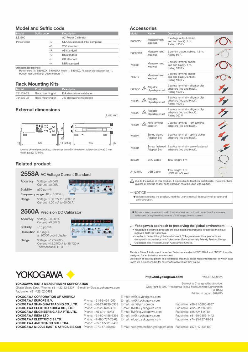
2558A AC Voltage Current Standard
Accuracy Voltage: ±0.04% Current: ±0.05%
Stability ±50 ppm/h
Frequency range 40 to 1000 Hz
Range Voltage: 1.00 mV to 1200.0 V Current: 1.00 mA to 60.00 A
2560A Precision DC Calibrator
Accuracy Voltage: ±0.005% Current: ±0.007%
Stability ±10 ppm/h
Resolution 6.5 digits, ±120000 count display
Range Voltage: ±1224.00 V Current: –12.2400 A to 36.720 A Thermocouple, RTD
External dimensions
Unless otherwise speci�ed, tolerances are ±3% (however, tolerances are ±0.3 mm when below 10 mm).
132
20
426 450 32(24.5)13 13
Unit: mm
Rack Mounting KitsModel Product Description
751535-E3 Rack mounting kit EIA standalone installation
751535-J3 Rack mounting kit JIS standalone installation
AccessoriesModel Name Description
B8506ZKMeasurement lead set
2 voltage output cables (red and black). 1 m. Rating 1500 V
B8506WAMeasurement lead set
2 current output cables. 1.5 m. Rating 80 A
758933Measurement lead set
2 safety terminal cables (red and black). 1 m. Rating 1000 V
758917Measurement lead set
2 safety terminal cables (red and black). 0.75 m. Rating 1000 V
B8506ZL Alligator clipadapter set
2 safety terminal—alligator clip adapters (red and black). Rating 1500 V
758929 Alligator clipadapter set
2 safety terminal—alligator clip adapters (red and black). Rating 1000 V
758922 Alligator clipadapter set
2 safety terminal—alligator clip adapters (red and black). Rating 300 V
758921 Fork terminal adapter
2 safety terminal—fork terminal adapters (red and black).
758923Spring clamp Adapter Set
2 safety terminal—spring clamp adapters (red and black).
758931Screw fastened Adapter Set
2 safety terminal—screw fastened adapters (red and black).
366924 BNC Cable Total length: 1 m
A1421WL USB CableTotal length: 2 mUSB2.0 Hi-Speed
Due to the nature of this product, it is possible to touch its metal parts. Therefore, there is a risk of electric shock, so the product must be used with caution.
Model and Suffix codeModel Suffix code Description
LS3300 AC Power Calibrator
Power cord –D UL/CSA standard, PSE compliant
–F VDE standard
–R AS standard
–Q BS standard
–H GB standard
–N NBR standard
Standard accessories :Power cord (1), B8506ZK, B8506WA (each 1), B8506ZL Alligator clip adapter set (1),Rubber feet (2 sets (4)), User’s manual (1)
Related product


