Simulation of the Delft Jet-in-Hot-Coflow burner using transported ...
Upload
pratik-joshiCategory
view
5download
0description
ORIGINAL
Effect of the coflow stream on a plane wall jet
Syrine Ben Haj Ayech • Sabra Habli •
Nejla Mahjoub Saıd • Herve Bournot •
George Le Palec
Received: 24 May 2013 / Accepted: 3 May 2014
� Springer-Verlag Berlin Heidelberg 2014
Abstract We propose in this work to study an isothermal
and a non-isothermal laminar plane wall jet emerging in a
coflow steam. The numerical solution of the governing
equations was performed by a finite difference method. In
this work, we are interested in the study of the influence of
Grashof numbers on the wall jet emerging in a medium at
rest. Further, we will examine the effect of the coflow stream
on the behavior of the dynamic and thermal properties of the
wall jet subjected to a constant temperature. A comparison
with a simple wall jet is carried out. The results show that for
a buoyant wall jet, two parameters can influence the flow: the
inertial and buoyancy forces. The velocity effect indicates
that the potential core length increases with the velocity ratio.
We are also showed that when using a momentum length
scale, the normalized longitudinal maximum velocity can
reach an asymptotic curve at different velocity ratios.
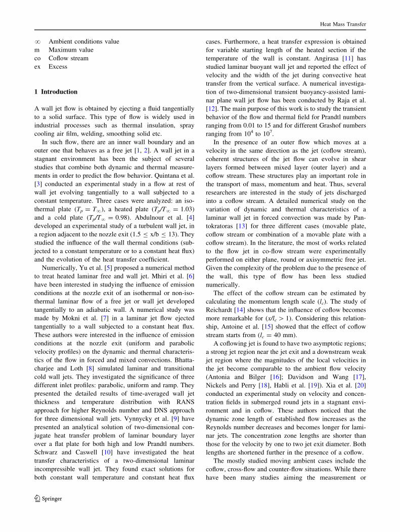
List of symbols
b Ejection nozzle thickness (m)
Cp Specific heat at constant pressure of the
fluid (J kg-1 k-1)
Gr Grashof number [Gr = gbb3(Tp - T?)/v2]
h Local convection coefficient (w m-2 k-1)
J Momentum discharged from the nozzle
exit (J = u02b) (m3 s-2)
Nu Local Nusselt number (Nu = hx/k)
Pr Prandtl number (Pr = lCp/k)
r Coflow velocity ratio (r = uco/u0)
Re Reynolds number (Re = u0b/v)
Rex Local Reynolds number (Rex = umx/v)
u, v Longitudinal and transverse components
of the velocity, respectively (m s-1)
uex = u - uco Longitudinal excess velocity (m s-1)
x, y Longitudinal and transversal coordinate
(m)
y0.5 Dynamic jet half-width, value of the
lateral distance at which longitudinal
velocity is half of the maximum
value (m)
Greek symbols
q Fluid density (kg m-3)
l Dynamic viscosity of the fluid (kg m-1 s-1)
k Thermal conductivity of the fluid (w m-1 k)
spWall shear stress sp ¼ l ou
oy
� �y¼0
� �, Pa
t Fluid kinematic viscosity (l/q) (m2 s-1)
a Thermal diffusivity of the fluid (m/Pr) (m2 s-1)
Subscripts
p Wall value
0 Value at the jet exit
S. B. H. Ayech
LGM, Ecole Nationale d’Ingenieurs de Monastir, Universite de
Monastir, Monastir, Tunisia
e-mail: [email protected]
S. Habli � N. M. Saıd (&)
LGM, ENIM, Institut Preparatoire aux Etudes d’Ingenieurs de
Monastir, Universite de Monastir, Monastir, Tunisia
e-mail: [email protected]; [email protected]
S. Habli
e-mail: [email protected]
H. Bournot � G. Le Palec
Aix-Marseille Universite, CNRS, IUSTI UMR 7343,
13013 Marseille, France
e-mail: [email protected]
G. Le Palec
e-mail: [email protected]
123
Heat Mass Transfer
DOI 10.1007/s00231-014-1372-7
? Ambient conditions value
m Maximum value
co Coflow stream
ex Excess
1 Introduction
A wall jet flow is obtained by ejecting a fluid tangentially
to a solid surface. This type of flow is widely used in
industrial processes such as thermal insulation, spray
cooling air film, welding, smoothing solid etc.
In such flow, there are an inner wall boundary and an
outer one that behaves as a free jet [1, 2]. A wall jet in a
stagnant environment has been the subject of several
studies that combine both dynamic and thermal measure-
ments in order to predict the flow behavior. Quintana et al.
[3] conducted an experimental study in a flow at rest of
wall jet evolving tangentially to a wall subjected to a
constant temperature. Three cases were analyzed: an iso-
thermal plate (Tp = T?), a heated plate (Tp/T? = 1.03)
and a cold plate (Tp/T? = 0.98). Abdulnour et al. [4]
developed an experimental study of a turbulent wall jet, in
a region adjacent to the nozzle exit (1.5 B x/b B 13). They
studied the influence of the wall thermal conditions (sub-
jected to a constant temperature or to a constant heat flux)
and the evolution of the heat transfer coefficient.
Numerically, Yu et al. [5] proposed a numerical method
to treat heated laminar free and wall jet. Mhiri et al. [6]
have been interested in studying the influence of emission
conditions at the nozzle exit of an isothermal or non-iso-
thermal laminar flow of a free jet or wall jet developed
tangentially to an adiabatic wall. A numerical study was
made by Mokni et al. [7] in a laminar jet flow ejected
tangentially to a wall subjected to a constant heat flux.
These authors were interested in the influence of emission
conditions at the nozzle exit (uniform and parabolic
velocity profiles) on the dynamic and thermal characteris-
tics of the flow in forced and mixed convections. Bhatta-
charjee and Loth [8] simulated laminar and transitional
cold wall jets. They investigated the significance of three
different inlet profiles: parabolic, uniform and ramp. They
presented the detailed results of time-averaged wall jet
thickness and temperature distribution with RANS
approach for higher Reynolds number and DNS approach
for three dimensional wall jets. Vynnycky et al. [9] have
presented an analytical solution of two-dimensional con-
jugate heat transfer problem of laminar boundary layer
over a flat plate for both high and low Prandtl numbers.
Schwarz and Caswell [10] have investigated the heat
transfer characteristics of a two-dimensional laminar
incompressible wall jet. They found exact solutions for
both constant wall temperature and constant heat flux
cases. Furthermore, a heat transfer expression is obtained
for variable starting length of the heated section if the
temperature of the wall is constant. Angirasa [11] has
studied laminar buoyant wall jet and reported the effect of
velocity and the width of the jet during convective heat
transfer from the vertical surface. A numerical investiga-
tion of two-dimensional transient buoyancy-assisted lami-
nar plane wall jet flow has been conducted by Raja et al.
[12]. The main purpose of this work is to study the transient
behavior of the flow and thermal field for Prandtl numbers
ranging from 0.01 to 15 and for different Grashof numbers
ranging from 104 to 107.
In the presence of an outer flow which moves at a
velocity in the same direction as the jet (coflow stream),
coherent structures of the jet flow can evolve in shear
layers formed between mixed layer (outer layer) and a
coflow stream. These structures play an important role in
the transport of mass, momentum and heat. Thus, several
researchers are interested in the study of jets discharged
into a coflow stream. A detailed numerical study on the
variation of dynamic and thermal characteristics of a
laminar wall jet in forced convection was made by Pan-
tokratoras [13] for three different cases (movable plate,
coflow stream or combination of a movable plate with a
coflow stream). In the literature, the most of works related
to the flow jet in co-flow stream were experimentally
performed on either plane, round or axisymmetric free jet.
Given the complexity of the problem due to the presence of
the wall, this type of flow has been less studied
numerically.
The effect of the coflow stream can be estimated by
calculating the momentum length scale (lc). The study of
Reichardt [14] shows that the influence of coflow becomes
more remarkable for (x/lc [ 1). Considering this relation-
ship, Antoine et al. [15] showed that the effect of coflow
stream starts from (lc = 40 mm).
A coflowing jet is found to have two asymptotic regions;
a strong jet region near the jet exit and a downstream weak
jet region where the magnitudes of the local velocities in
the jet become comparable to the ambient flow velocity
(Antonia and Bilger [16]; Davidson and Wang [17],
Nickels and Perry [18], Habli et al. [19]). Xia et al. [20]
conducted an experimental study on velocity and concen-
tration fields in submerged round jets in a stagnant envi-
ronment and in coflow. These authors noticed that the
dynamic zone length of established flow increases as the
Reynolds number decreases and becomes longer for lami-
nar jets. The concentration zone lengths are shorter than
those for the velocity by one to two jet exit diameter. Both
lengths are shortened further in the presence of a coflow.
The mostly studied moving ambient cases include the
coflow, cross-flow and counter-flow situations. While there
have been many studies aiming the measurement or
Heat Mass Transfer
123
prediction of jet behavior in those moving environments
and in stagnant ambient (Fischer et al. [21]; Wood et al.
[22]; Jirka [23]), most of them investigated the ‘‘far field’’
of the jet, or the zone of established flow (ZEF). In the
ZEF, self similarity behavior is observed on the spreading
of the jet as measured by various mean flow properties
including the growth of jet width, the decay of jet center-
line properties with axial distance, and the radial profiles of
velocity and concentration. Lam et al. [24] presented an
experimental study of a round jet in a stagnant fluid and in
a moving environment of the coflow, counter-flow or cross-
flow situation in the region near the jet exit. The aim of this
work is to determine: the evolution of the axis velocity in
the potential core and in the established flow areas, the
effect of the external flow on the jet fictitious origin and the
length of the potential core. While results show that the
decay constant is increased by a coflow but reduced by a
counter-flow or a cross-flow; the virtual origin was found to
be affected as well. Furthermore, increasing the external
velocity (for a coflow, counter-flow or cross-flow), causes a
slight decrease in the potential core length.
The main objective of this work is to study the effect of the
velocity ratio on the dynamic and thermal behavior of the wall
jet discharged into a coflowing air stream. A comparison with
a wall jet in a medium at rest was carried out. Further, we will
examine the influence of Grashof numbers on the wall jet
emerging in coflow and in a in a medium at rest.
2 Numerical modeling
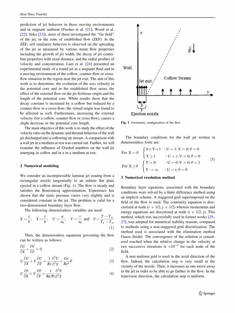
We consider an incompressible laminar jet issuing from a
rectangular nozzle tangentially to an infinite flat plate
ejected in a coflow stream (Fig. 1). The flow is steady and
satisfies the Boussinesq approximation. Experience has
shown that the static pressure varies very slightly and is
considered constant in the jet. The problem is valid for a
two-dimensional boundary layer flow.
The following dimensionless variables are used:
X ¼ x
b; Y ¼ y
b; U ¼ u
u0
; V ¼ v
u0
and h ¼ T � T1Tp � T1
ð1Þ
Then, the dimensionless equations governing the flow
can be written as follows:
oU
oXþ oV
oY¼ 0 ð2Þ
UoU
oXþ V
oU
oY¼ 1
Re
o2U
o2Yþ Gr
Re2h ð3Þ
UohoXþ V
ohoY¼ 1
Re Pr
o2h
o2Yð4Þ
The boundary conditions for the wall jet written in
dimensionless form are:
For X ¼ 00\Y\1 : U ¼ 1; V ¼ 0; h ¼ 0
Y� 1 : U ¼ r; V ¼ 0; h ¼ 0
(
For X� 0Y ¼ 0 : U ¼ 0; V ¼ 0; h ¼ 1
Y!1 : U ¼ r; h ¼ 0
( ð5Þ
3 Numerical resolution method
Boundary layer equations, associated with the boundary
conditions were solved by a finite difference method using
an implicit scheme. A staggered grid superimposed on the
field of the flow is used. The continuity equation is dise-
cretized at node (i ? 1/2, j ? 1/2) whereas momentum and
energy equations are discretized at node (i ? 1/2, j). This
method, which was successfully used in former works [25–
27], was adopted for numerical stability reasons, compared
to methods using a non-staggered grid discretization. The
method used is associated with the elimination method
Gauss–Seidel. The convergence of the solution is consid-
ered reached when the relative change in the velocity at
two successive iterations is \10-4 for each node of the
field.
A non uniform grid is used in the axial direction of the
flow. Indeed, the calculation step is very small in the
vicinity of the nozzle. Then, it increases as one move away
in the jet in order to be able to go farther in the flow. In the
transverse direction, the calculation step is uniform.
Fig. 1 Geometric configuration of the flow
Heat Mass Transfer
123

To study the effect of the mesh sensibility on the results,
we tested different calculation steps in the longitudinal and
in the transverse directions. Figure 2 shows the transverse
evolution of the vertical velocity normalized by the max-
imum velocity for different calculation steps for an iso-
thermal jet discharged into a flow at rest and for different
heights of the jet (X = 12, X = 16 and X = 20).
The examination of the Fig. 2a–c, shows that there is a
perfect agreement between the velocity profiles in the
boundary layer region between the wall and the reduced
iso-velocity UUm¼ 1
� �for the three test cases (mesh 1,
mesh 2 and mesh 3). However, the difference is more
pronounced between results obtained with meshes 2 and 3
and those obtained using mesh 3 in the outer boundary
layer region.
In the transverse direction, we tested also the sensitivity
of the mesh on the longitudinal evolution of the maximum
velocity for three steps. Figure 3 shows that taking
DY = 10-2 is sufficient obtain accurate results.
4 Results and discussion
4.1 Validation of numerical results
To test the validity of numerical data, we have compared
the numerical results with experimental ones cited in the
literature; i.e., the boundary conditions adopted in this
study correspond closely to those of Quintana et al. [3].
In Fig. 4a, b, we represent lateral profiles of the longi-
tudinal velocity normalized by the maximum longitudinal
velocity, the transversal coordinate is normalized by the
dynamic half-width for different stations of the jet
(X = 12, X = 16 and X = 20). These figures show the
experimental results suggested by Quintana et al. [3],
respectively, for the cases: heated wall (Fig. 4a) and cold
wall (Fig. 4b).
We noticed a good agreement between the numerical
results and the experimental data at different downstream
Fig. 2 Effect of the mesh on the transverse evolution of the vertical velocity normalized by the maximum velocity for DY = 10-2
Fig. 3 Effect of the mesh on the longitudinal evolution of the
maximum velocity for mesh 2 (DX = 10-2 for X B 10 and
DX = 10-1 for X [ 10)
Heat Mass Transfer
123
stations. Further, it is well known that when cooling is
applied, the velocity gradient in the inner region of the
boundary layer increases and the maximum velocity is
moved closer to the wall. Otherwise, reverse effect is
observed for a heated wall. However, in this study, the
difference between results for the three cases is negligible
because the temperature difference between the wall and
the exterior is relatively low for heated and cold walls and
flow tends to an isothermal flow.
4.2 Isothermal flow
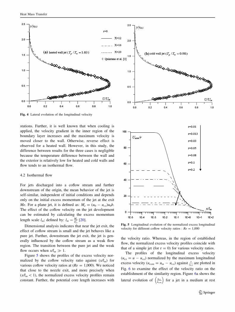
For jets discharged into a coflow stream and further
downstream of the origin, the mean behavior of the jet is
self-similar, independent of initial conditions and depends
only on the initial excess momentum of the jet at the exit
Me. For a plane jet, it is defined as: Me = (u0 - uco)u0b.
The effect of the coflow velocity on the jet development
can be estimated by calculating the excess momentum
length scale lm; defined by: lm ¼ Me
u2co
[20].
Dimensional analysis indicates that near the jet exit, the
effect of coflow stream is small and the jet behaves like a
pure jet. Further, downstream the jet exit, the jet is gen-
erally influenced by the coflow stream as a weak flow
region. The transition between the pure jet and the weak
flow occurs when x/lm � 1.
Figure 5 shows the profiles of the excess velocity nor-
malized by the coflow velocity ratio against (x/lm) for
various coflow velocity ratios at (Re = 1,000). We noticed
that close to the nozzle exit, and more precisely when
(x/lm \ 1), the normalized excess velocity profiles remain
constant. Further, the potential core length increases with
the velocity ratio. Whereas, in the region of established
flow, the normalized excess velocity profiles coincide with
that of a simple jet (for r = 0) for various velocity ratios.
The profiles of the longitudinal excess velocity
(uex = u - uco) normalized by the maximum longitudinal
excess velocity (uexm = um - uco) against yy0:5
are plotted in
Fig. 6 to examine the effect of the velocity ratio on the
establishment of the similarity region. Figure 6a shows the
lateral evolution of uex
uexm
� �for a jet in a medium at rest
Fig. 4 Lateral evolution of the longitudinal velocity
Fig. 5 Longitudinal evolution of the normalized excess longitudinal
velocity for different coflow velocity ratios : Re = 1,000
Heat Mass Transfer
123
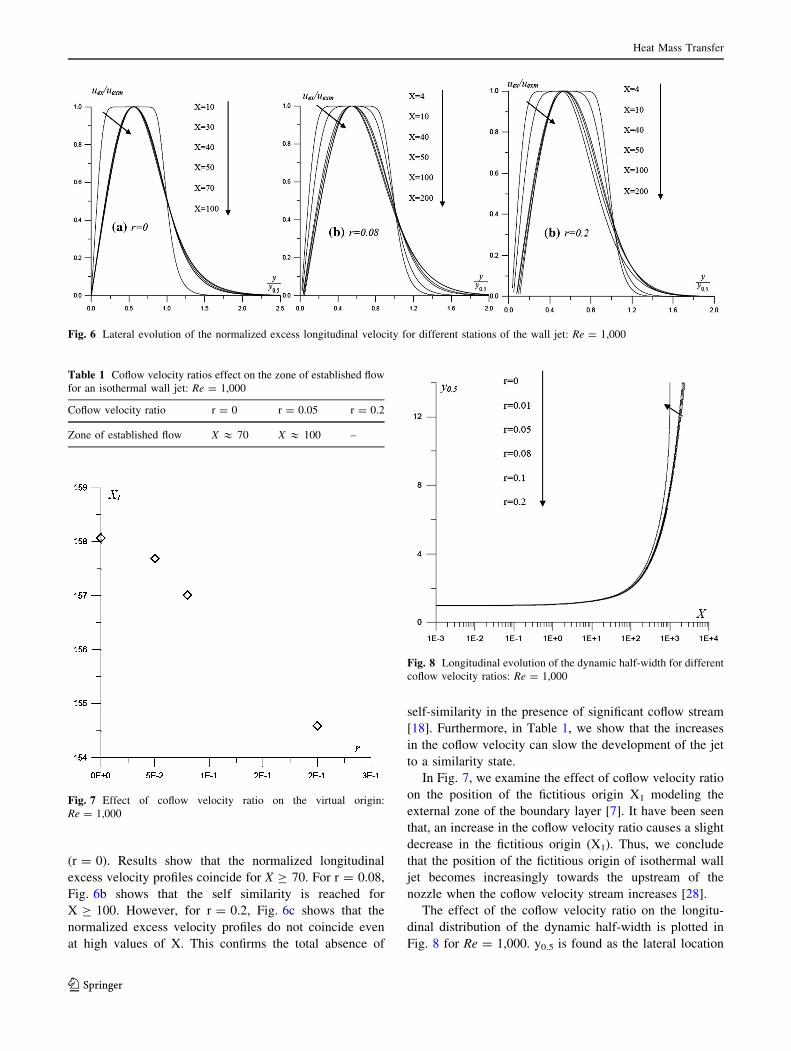
(r = 0). Results show that the normalized longitudinal
excess velocity profiles coincide for X C 70. For r = 0.08,
Fig. 6b shows that the self similarity is reached for
X C 100. However, for r = 0.2, Fig. 6c shows that the
normalized excess velocity profiles do not coincide even
at high values of X. This confirms the total absence of
self-similarity in the presence of significant coflow stream
[18]. Furthermore, in Table 1, we show that the increases
in the coflow velocity can slow the development of the jet
to a similarity state.
In Fig. 7, we examine the effect of coflow velocity ratio
on the position of the fictitious origin X1 modeling the
external zone of the boundary layer [7]. It have been seen
that, an increase in the coflow velocity ratio causes a slight
decrease in the fictitious origin (X1). Thus, we conclude
that the position of the fictitious origin of isothermal wall
jet becomes increasingly towards the upstream of the
nozzle when the coflow velocity stream increases [28].
The effect of the coflow velocity ratio on the longitu-
dinal distribution of the dynamic half-width is plotted in
Fig. 8 for Re = 1,000. y0.5 is found as the lateral location
Fig. 6 Lateral evolution of the normalized excess longitudinal velocity for different stations of the wall jet: Re = 1,000
Table 1 Coflow velocity ratios effect on the zone of established flow
for an isothermal wall jet: Re = 1,000
Coflow velocity ratio r = 0 r = 0.05 r = 0.2
Zone of established flow X & 70 X & 100 –
Fig. 7 Effect of coflow velocity ratio on the virtual origin:
Re = 1,000
Fig. 8 Longitudinal evolution of the dynamic half-width for different
coflow velocity ratios: Re = 1,000
Heat Mass Transfer
123

where uum¼ 1
2. The width of the jet is 2y0.5. Near the jet exit,
half-width profiles remain constant and similar for various
coflow velocity ratios. This means that the secondary flow
velocity variation has no effect on the dynamic half-width
in the potential core area. Downstream of the jet exit, a
difference between results appears. This difference
becomes significant in the ZEF. Further, an increase in the
coflow velocity ratio leads to an increase in the dynamic
half-width.
In Fig. 9, we examine the longitudinal distribution of the
normalized wall shear stress in the form ofspm2
qJ2
� �for dif-
ferent coflow velocity ratios. The analysis of this figure
shows that the normalized wall shear stress remains constant
in the potential core region, then decreases with height x.
We also notice that the profiles of the shear stress coincide
with that of a simple wall jet, for various coflow velocities
up to large distances xJm2
� �where the coflow stream effect
occurs. Far away from the jet exit, results show that the
effect of velocity ratio is negligible for (r \ 0.1) and the jet
behaves like a simple wall jet (wall jet flow at rest).
Otherwise, for (r C 0.1), the introduction of such pertur-
bation leads to a remarkable increase in the wall shear stress.
4.3 Non-isothermal flow
4.3.1 Buoyant wall jet in a flow at rest
In Fig. 10, we represent the axial evolution of the maximum
longitudinal velocity for different Grashof numbers at
Re = 1,500. For small values of X, the maximum velocity
remains unchanged and equal to the velocity at the nozzle
exit. Far away from the nozzle exit, for a wall jet in forced
convection (Gr = 0), the maximum longitudinal velocity
decreases as a function of X. Furthermore, under the effect of
buoyancy forces, when the Grashof number increases the
maximum velocity of the buoyant wall jet increases with X.
Indeed, in a buoyant wall jet, three regions exist. The first,
which occurs near the jet exit, is a pure jet similar to an
isothermal flow, where buoyancy effects are negligible
compared to the inertial forces. In this region, the maximum
velocity remains constant and approximately equal to its
value at the nozzle exit for different Grashof numbers. This
region is followed by the transition zone where the buoyancy
and inertia play equally important roles. In this region, the
maximum velocity may go above or below the value at the
output of the jet depending on the size of the buoyancy forces
and inertia. The third region, where the flow is away from the
source, which is a plume, inertia effects are negligible and
the buoyancy becomes the only important parameter. In this
region, the maximum velocity increases with the distance X.
Further, an increase in Grashof number leads to a shortening
of the length of the pure jet region, and therefore the maxi-
mum velocity reaches faster the region of established flow.
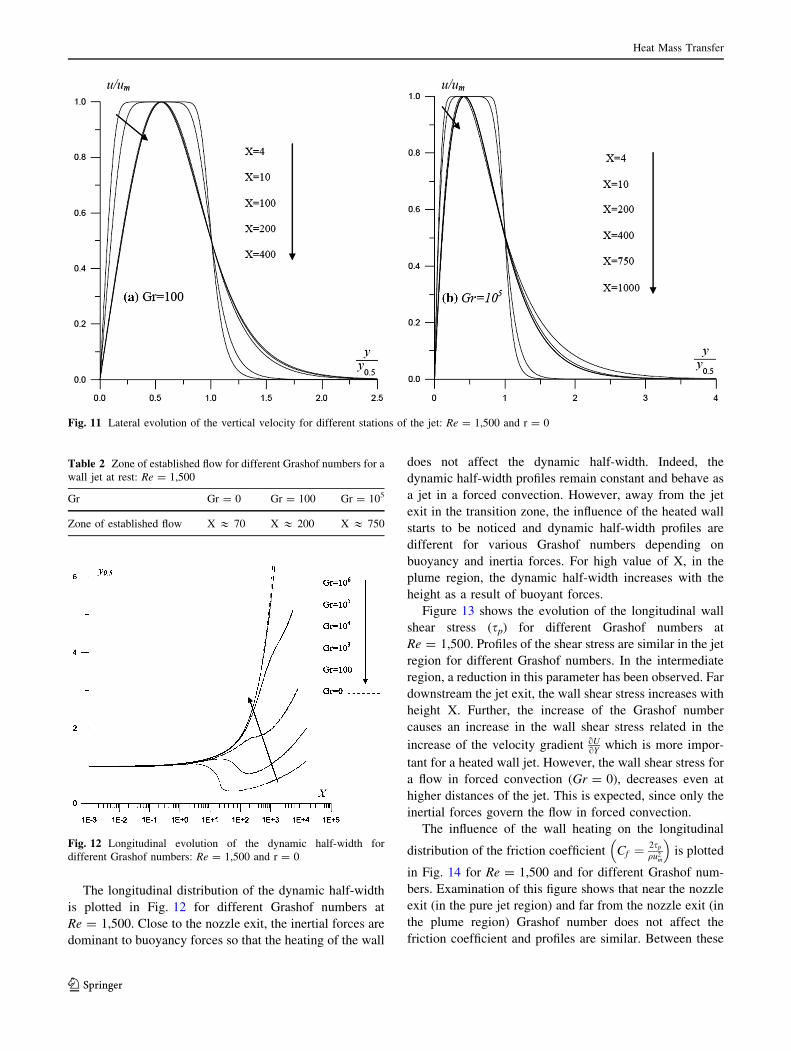
We present in Fig. 11, the evolution of the longitudinal
velocity normalized by the maximum longitudinal velocity
against yy0:5
at various stations of the jet for Gr = 100 and
Gr = 105.
For Gr = 100 (Fig. 11a), the longitudinal velocity pro-
files become similar from a distance X = 200. Otherwise,
for Gr = 105 the similarity starts farthest for X = 750
(Fig. 11b). The comparison of these results, in Table 2,
shows that the decrease in the Grashof number accelerates
the development of the jet to a similarity state.
Fig. 9 Longitudinal evolution of the normalized wall shear stress for
different coflow velocity ratios: Re = 1,000
Fig. 10 Longitudinal evolution of the maximum longitudinal veloc-
ity for different Grashof numbers : Re = 1,500 and r = 0
Heat Mass Transfer
123
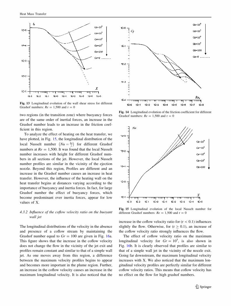
The longitudinal distribution of the dynamic half-width
is plotted in Fig. 12 for different Grashof numbers at
Re = 1,500. Close to the nozzle exit, the inertial forces are
dominant to buoyancy forces so that the heating of the wall
does not affect the dynamic half-width. Indeed, the
dynamic half-width profiles remain constant and behave as
a jet in a forced convection. However, away from the jet
exit in the transition zone, the influence of the heated wall
starts to be noticed and dynamic half-width profiles are
different for various Grashof numbers depending on
buoyancy and inertia forces. For high value of X, in the
plume region, the dynamic half-width increases with the
height as a result of buoyant forces.
Figure 13 shows the evolution of the longitudinal wall
shear stress (sp) for different Grashof numbers at
Re = 1,500. Profiles of the shear stress are similar in the jet
region for different Grashof numbers. In the intermediate
region, a reduction in this parameter has been observed. Far
downstream the jet exit, the wall shear stress increases with
height X. Further, the increase of the Grashof number
causes an increase in the wall shear stress related in the
increase of the velocity gradient oUoY
which is more impor-
tant for a heated wall jet. However, the wall shear stress for
a flow in forced convection (Gr = 0), decreases even at
higher distances of the jet. This is expected, since only the
inertial forces govern the flow in forced convection.
The influence of the wall heating on the longitudinal
distribution of the friction coefficient Cf ¼ 2sp
qu2m
� �is plotted
in Fig. 14 for Re = 1,500 and for different Grashof num-
bers. Examination of this figure shows that near the nozzle
exit (in the pure jet region) and far from the nozzle exit (in
the plume region) Grashof number does not affect the
friction coefficient and profiles are similar. Between these
Fig. 11 Lateral evolution of the vertical velocity for different stations of the jet: Re = 1,500 and r = 0
Table 2 Zone of established flow for different Grashof numbers for a
wall jet at rest: Re = 1,500
Gr Gr = 0 Gr = 100 Gr = 105
Zone of established flow X & 70 X & 200 X & 750
Fig. 12 Longitudinal evolution of the dynamic half-width for
different Grashof numbers: Re = 1,500 and r = 0
Heat Mass Transfer
123
two regions (in the transition zone) where buoyancy forces
are of the same order of inertial forces, an increase in the
Grashof number leads to an increase in the friction coef-
ficient in this region.
To analyze the effect of heating on the heat transfer, we
have plotted, in Fig. 15, the longitudinal distribution of the
local Nusselt number Nu ¼ hxk
� �for different Grashof
numbers at Re = 1,500. It was found that the local Nusselt
number increases with height for different Grashof num-
bers in all sections of the jet. However, the local Nusselt
number profiles are similar in the vicinity of the ejection
nozzle. Beyond this region, Profiles are different and an
increase in the Grashof number causes an increase in heat
transfer. However, the influence of the heating wall on the
heat transfer begins at distances varying according to the
importance of buoyancy and inertia forces. In fact, for large
Grashof number the effect of buoyancy forces, which
become predominant over inertia forces, appear for low
values of X.
4.3.2 Influence of the coflow velocity ratio on the buoyant
wall jet
The longitudinal distributions of the velocity in the absence
and presence of a coflow stream by maintaining the
Grashof number equal to Gr = 100 are given in Fig. 16a.
This figure shows that the increase in the coflow velocity
does not change the flow in the vicinity of the jet exit and
profiles remain constant and similar to that of a simple wall
jet. As one moves away from this region, a difference
between the maximum velocity profiles begins to appear
and becomes more important in the plume region. Further,
an increase in the coflow velocity causes an increase in the
maximum longitudinal velocity. It is also noticed that the
increase in the coflow velocity ratio for (r \ 0.1) influences
slightly the flow. Otherwise, for (r C 0.1), an increase of
the coflow velocity ratio strongly influences the flow.
The effect of coflow velocity ratio on the maximum
longitudinal velocity for Gr = 105, is also shown in
Fig. 16b. It is clearly observed that profiles are similar to
that of a simple wall jet in the vicinity of the nozzle exit.
Going far downstream, the maximum longitudinal velocity
increases with X. We also noticed that the maximum lon-
gitudinal velocity profiles are perfectly similar for different
coflow velocity ratios. This means that coflow velocity has
no effect on the flow for high grashof numbers.
Fig. 13 Longitudinal evolution of the wall shear stress for different
Grashof numbers: Re = 1,500 and r = 0
Fig. 14 Longitudinal evolution of the friction coefficient for different
Grashof numbers: Re = 1,500 and r = 0
Fig. 15 Longitudinal evolution of the local Nusselt number for
different Grashof numbers: Re = 1,500 and r = 0
Heat Mass Transfer
123

The effect of coflow velocity ratio on lateral evolution
of the longitudinal excess velocity (uex = u - uco) nor-
malized by the maximum longitudinal excess velocity
(uexm = um - uco) with height X is represented in Fig. 17
for Gr = 100 and Re = 1,500. The results, summarized in
Table 3, show that similarity is slower for higher coflow
velocity. However, for a stronger coflow velocity, the
absence of a complete similarity is observed [24].
The longitudinal distribution of the dynamic half-width
is shown, in Fig. 18a, for Gr = 100 and Re = 1,500. In the
vicinity of the nozzle exit, dynamic half-width profiles
coincide with that of a simple wall jet and coflow has no
influence on this parameter in this region. However, away
from this region, an increase in the velocity ratio leads to an
increase in this parameter. It is also noticed that for r \ 0.1,
the dynamic half-width is slightly influenced by the varia-
tion of the coflow velocity and this type of jet behaves as a
simple flow at rest. Though, for r C 0.1, the influence of the
coflow velocity becomes more pronounced.
The longitudinal evolution of the dynamic half-width for
Gr = 105 (flow in mixed convection) and Re = 1,500 is
given in Fig. 18b. Results show that profiles are similar in
the pure jet area and in the plume region. Between these
Fig. 16 Longitudinal evolution of the maximum longitudinal velocity for different coflow velocity ratios: Gr = 100 and Re = 1,500
Fig. 17 Lateral evolution of the normalized excess longitudinal velocity for different stations of the wall jet: Gr = 100 and Re = 1,500
Table 3 Coflow velocity ratios effect on the zone of established flow
for a buoyant wall jet: Gr = 100 and Re = 1,500
Coflow velocity ratio r = 0 r = 0.05 r = 0.2
Zone of established flow X & 200 X & 200 –
Heat Mass Transfer
123
two regions in (the intermediate zone), a difference
between results was observed.
The longitudinal evolution of the wall shear stress for
various coflow velocity ratios for Gr = 100 and
Re = 1,500 is discussed in (Fig. 19a). It is observed that
the increase in the coflow velocity causes a slight increase
in shear stress only for higher locations of the jet. However,
for a wall jet in mixed convection (Fig. 19b), the increase
in the coflow velocity has no effect on sp in all stations of
the jet.
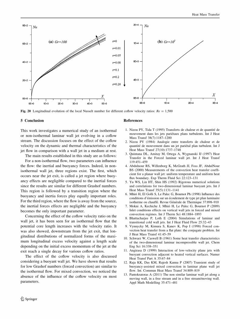
To analyze the effect of the coflow velocity on the heat
transfer between the jet and the heated wall, we present in
Fig. 20a, the longitudinal evolution of the local Nusselt
number for Gr = 100 and Re = 1,500. From this figure,
we noticed an increase in the heat transfer in all sections of
the jet. Further, near the jet exit, the local Nusselt number
profiles are similar to that of a wall jet at rest and coflow
has no influence in this region. Away from this region, a
difference between profiles is observed. Indeed, it is dis-
covered that the heat exchange is higher for a stronger
coflow and becomes more important from r C 0.1. Other-
wise, for a Grashof number equal to Gr = 105 (Fig. 20b),
local Nusselt number profiles are not influenced by the
coflow and results are similar.
Fig. 18 Longitudinal evolution of the dynamic half-width for different coflow velocity ratios: Re = 1,500
Fig. 19 Longitudinal evolution of the wall shear stress for different coflow velocity ratios: Re = 1,500
Heat Mass Transfer
123
5 Conclusion
This work investigates a numerical study of an isothermal
or non-isothermal laminar wall jet evolving in a coflow
stream. The discussion focuses on the effect of the coflow
velocity on the dynamic and thermal characteristics of the
jet flow in comparison with a wall jet in a medium at rest.
The main results established in this study are as follows:
For a non-isothermal flow, two parameters can influence
the flow: the inertial and buoyancy forces. Indeed, in non-
isothermal wall jet, three regions exist. The first, which
occurs near the jet exit, is called a jet region where buoy-
ancy effects are negligible compared to the inertial forces
since the results are similar for different Grashof numbers.
This region is followed by a transition region where the
buoyancy and inertia forces play equally important roles.
For the third region, where the flow is away from the source,
the inertial forces effects are negligible and the buoyancy
becomes the only important parameter.
Concerning the effect of the coflow velocity ratio on the
wall jet, it has been seen for an isothermal flow that the
potential core length increases with the velocity ratio. It
was also showed, downstream from the jet exit, that lon-
gitudinal distributions of normalized forms of the maxi-
mum longitudinal excess velocity against a length scale
depending on the initial excess momentum of the jet at the
exit reach a single decay for various coflow ratios.
The effect of the coflow velocity is also discussed
considering a buoyant wall jet. We have shown that results
for low Grashof numbers (forced convection) are similar to
the isothermal flow. For mixed convection, we noticed the
absence of the influence of the coflow velocity on most
parameters.
References
1. Nizou PY, Tida T (1995) Transferts de chaleur et de quantite de
mouvement dans les jets parietaux plans turbulents. Int J Heat
Mass Transf 38(7):1187–1200
2. Nizou PY (1984) Analogie entre transferts de chaleur et de
quantite de mouvement dans un jet parietal plan turbulent. Int J
Heat Mass Transf 27(10):1737–1748
3. Quintana DL, Amitay M, Ortega A, Wygnanski IJ (1997) Heat
Transfer in the Forced laminar wall jet. Int J Heat Transf
119:451–459
4. Abdulnour RS, Willenborg K, McGrath JJ, Foss JF, AbdulNour
BS (2000) Measurements of the convection heat transfer coeffi-
cient for a planar wall jet: uniform temperature and uniform heat
flux boundary. Exp Therm Fluid Sci 22:123–131
5. Yu WS, Lin HT, Shin HS (1992) Rigorous numerical solutions
and correlations for two-dimensional laminar buoyant jets. Int J
Heat Mass Transf 35(5):1131–1141
6. Mhiri H, El Golli S, Le Palec G, Bournot Ph (1998) Influence des
conditions d’emission sur un ecoulement de type jet plan laminaire
isotherme ou chauffe. Revue Generale de Thermique 37:898–910
7. Mokni A, Kechiche J, Mhiri H, Le Palec G, Bournot P (2009)
Inlet conditions effects on vertical wall jets in forced and mixed
convection regimes. Int J Therm Sci 48:1884–1893
8. Bhattacharjee P, Loth E (2004) Simulations of laminar and
transitional cold wall jets. Int J Heat Fluid Flow 25:32–43
9. Vynnycky M, Kimura S, Kanev K, Pop I (1998) Forced con-
vection heat transfer from a flat plate: the conjugate problem. Int
J Heat Mass Transf 41:45–59
10. Schwarz W, Caswell B (1961) Some heat transfer characteristics
of the two-dimensional laminar incompressible wall jet. Chem
Eng Sci 16:338–351
11. Angirasa D (1999) Interaction of low-velocity plane jets with
buoyant convection adjacent to heated vertical surfaces. Numer
Heat Transf Part A 35:67–84
12. Raja KK, Das KM, Rajesh Kanna P (2007) Transient study of
buoyancy-assisted mixed convection in laminar plane wall jet
flow. Int. Commun Heat Mass Transf 34:809–819
13. Pantokratoras A (2011) The non similar laminar wall jet along a
moving wall, in a free stream and in a free stream/moving wall.
Appl Math Modelling 35:471–481
Fig. 20 Longitudinal evolution of the local Nusselt number for different coflow velocity ratios: Re = 1,500
Heat Mass Transfer
123
14. Reichardt H (1964) Turbulence Strahlausbreitung in gleichge-
richteter Grundstromung. Forsch Ingenieurwes 30:133–164
15. Antoine Y, Lemoine F, Lebouche M (2001) Turbulent transport
of a passive scalar in a round jet discharging into a coflowing
stream. Eur J Mech B Fluids 20:275–301
16. Antonia RA, Bilger RW (1973) An experimental investigation of
an axisymmetric jet in a coflowing air stream. J Fluid Mech
61:805–822
17. Davidson MJ, Wang HJ (2002) Strongly advected jet in a coflow.
J Hydraul Eng 128(8):742–752
18. Nickels TB, Perry AE (1996) An experimental and theoreti-
cal study of the turbulent coflowing jet. J Fluid Mech
309:157–182
19. Habli S, Mahjoub Saıd N, Le Palec G, Bournot P (2008) Influ-
ence of a coflowing ambient stream on a turbulent axisymmetric
buoyant jet. J Heat Transf 130(2):22201–22400
20. Xia LP, Lam KM (2009) Velocity and concentration measure-
ments in initial region of submerged round jets in stagnant
environment and in co flow. J Hydro-Environ Res 3:21–34
21. Fischer HB, List EJ, Koh RCY, Imberger J, Brooks NH
(1979) Mixing in Inland and coastal waters. Academic Press,
New York
22. Wood IR, Bell BG, Wilkinson DL (1993) Ocean disposal of
wastewater. Int Adv Ser Ocean Eng 8. World Scientific,
RiverEdge
23. Jirka GH (2004) Integral model for turbulent buoyant jets in
unbounded stratified flows, Part 1: the single round jet. Environ
Fluid Mech 4(1):1–56
24. Or CM, Lam KM, Liu P (2011) Potential core lengths of round
jets in stagnant and moving environments. J Hydro-Environ Res
5:81–91
25. Mhiri H, Habli S, El Golli S, Le Palec G, Bournot Ph (1999)
Etude numerique des conditions d’emission sur un ecoulement de
type jet plan turbulent isotherme ou chauffe. Int J Therm Sci
38:904–915
26. Habli S, Mhiri H, Golli S, Le Palec G, Bournot Ph (2001) Etude
numerique des conditions d’emission sur un ecoulement de type
jet axisymetrique turbulent. Int J Therm Sci 40:497–511
27. Kechiche J (2006) Application des modeles de turbulence a bas
nombre de Reynolds pour l’etude des jets parietaux turbulents.
Ph. D. Thesis, Universite de la Mediterranee, France, Universite
de Monastir, Tunisie
28. Pope SB (1978) An explanation of the round jet/plane jet
anomaly. AIAA J 16:279–281
Heat Mass Transfer
123