
Effect of radial base-plate welds on ULCF capacity of unanchored ...
9
Effect of radial base-plate welds on ULCF capacity of unanchored tank connections Gary S. Prinz a, ⁎, Alain Nussbaumer b a Dept. of Civil Engineering, University of Arkansas, Fayetteville, AR 72701, United States b Steel Structures Laboratory (ICOM), Swiss Federal Institute of Technology (EPFL), Switzerland abstract article info Article history: Received 22 October 2013 Accepted 7 August 2014 Available online xxxx Keywords: Ultra low-cycle fatigue Unanchored liquid storage tanks Fracture Earthquake engineering The base of large steel liquid storage tanks can uplift during severe earthquakes, causing large inelastic rotations at the connection between the tank shell and tank base. While recent experimental studies indicate significantly higher connection rotation capacity than what is specified in the current Eurocode standard (set at 0.2 rad), ad- ditional radial base-plate welds (present in some tank connection details due to fabrication methods) have never been considered in tests. This study experimentally investigates the effects of these radial base-plate welds on the fatigue capacity of tank shell-to-base connections during uplift. Twelve tank shell-to-base connection specimens taken from existing tanks throughout Switzerland are tested at rotation ranges greater than the current Eurocode limit (eight specimens with radial welds and four specimens without radial welds). Testing indicates that tank base-plate sections containing radial welds govern the shell-to-base rotation capacity during uplift. The rotation capacity of connections containing radial welds was nearly 30% lower (on average) than equivalent connections without radial welds. This reduced capacity is directly related to the reduced base-plate ductility created by the radial weld heat affected zone. All connection capacities were far greater than the current Eurocode limit. © 2014 Elsevier Ltd. All rights reserved. 1. Introduction Large steel liquid storage tanks are often designed and constructed without attachments or anchors to the supporting foundation. In these tanks, called herein unanchored tanks, the weight of the stored liquid and weight of the tank structure itself are usually sufficient to prevent sliding or complete overturning of the tank during severe earthquakes; however, the possibility still exists for the tank to rock and for the base of the tank to uplift from the foundation. The process of tank base uplifting can generate large inelastic strains within the base-plate connections [1–5], potentially leading to ultra- low-cycle fatigue damage. Current European standards limit the amount of permissible tank-base uplift by limiting the amount of rota- tion at the connection between the tank base and tank shell. The shell-to-base rotation limit in the current version of Eurocode 8 (EC8- 4) is fixed at 0.2 rad [6]. Because large steel liquid storage tanks are typically constructed by welding together much smaller steel plate sections, similar to construction of a patchwork quilt, there are two shell-to-base con- nection configurations to consider: 1) connections contained within an entire base-plate section having only circumferential welds (welds between the base-plate and shell), and 2) connections at the junction of two base-plate sections having both circumferential and radial welds (radial welds are created when two adjacent base- plate sections are joined). Fig. 1 shows a typical tank assembly, with the tank base having multiple pentagonal sections near the tank edge, forming a ring for connection of the tank shell. Connections having only circumferential welds have been fatigue tested in two recent stud- ies [7,8]; however, connections with both radial and circumferential welds have not been tested. Experimental testing of tank shell-to-base connections having only circumferential shell-to-base welds indicate a significant increase in fa- tigue capacity with increased base-plate ductility [8], and significantly higher rotation capacity than the current EC8-4 limit. Because base- plate ductility has such a strong influence on fatigue performance, potential changes due to the presence of radial welds could have signif- icant effect on fatigue capacity. The performance of tank connections containing radial welds relative to the existing EC8-4 limit is unknown. This paper expands upon the experimental work in [7,8] by: 1) examining the effects of radial base-plate welds on connection ca- pacity, 2) expanding current experimental data taken from existing tank connections, and 3) creating additional fatigue–life curves for fatigue evaluation of tank connections having radial welds. The paper begins by describing the experimental investigation to de- termine the rotation capacity of tank shell-to-base connections under constant range uplift cycles. Included in the description are the test setup, instrumentation, cyclic loading protocol, and detail of test speci- mens used. Next, fatigue results from the testing are discussed, fatigue–life curves are created, and conclusions regarding connection Journal of Constructional Steel Research 103 (2014) 131–139 ⁎ Corresponding author. E-mail address: [email protected] (G.S. Prinz). http://dx.doi.org/10.1016/j.jcsr.2014.08.004 0143-974X/© 2014 Elsevier Ltd. All rights reserved. Contents lists available at ScienceDirect Journal of Constructional Steel Research
Transcript of Effect of radial base-plate welds on ULCF capacity of unanchored ...

Journal of Constructional Steel Research 103 (2014) 131–139
Contents lists available at ScienceDirect
Journal of Constructional Steel Research
Effect of radial base-plate welds on ULCF capacity of unanchoredtank connections
Gary S. Prinz a,⁎, Alain Nussbaumer b
a Dept. of Civil Engineering, University of Arkansas, Fayetteville, AR 72701, United Statesb Steel Structures Laboratory (ICOM), Swiss Federal Institute of Technology (EPFL), Switzerland
⁎ Corresponding author.E-mail address: [email protected] (G.S. Prinz).
http://dx.doi.org/10.1016/j.jcsr.2014.08.0040143-974X/© 2014 Elsevier Ltd. All rights reserved.
a b s t r a c t
a r t i c l e i n f oArticle history:Received 22 October 2013Accepted 7 August 2014Available online xxxx
Keywords:Ultra low-cycle fatigueUnanchored liquid storage tanksFractureEarthquake engineering
The base of large steel liquid storage tanks can uplift during severe earthquakes, causing large inelastic rotationsat the connection between the tank shell and tank base. While recent experimental studies indicate significantlyhigher connection rotation capacity than what is specified in the current Eurocode standard (set at 0.2 rad), ad-ditional radial base-plate welds (present in some tank connection details due to fabricationmethods) have neverbeen considered in tests. This study experimentally investigates the effects of these radial base-platewelds on thefatigue capacity of tank shell-to-base connections during uplift. Twelve tank shell-to-base connection specimenstaken from existing tanks throughout Switzerland are tested at rotation ranges greater than the current Eurocodelimit (eight specimens with radial welds and four specimens without radial welds). Testing indicates that tankbase-plate sections containing radial welds govern the shell-to-base rotation capacity during uplift. The rotationcapacity of connections containing radial welds was nearly 30% lower (on average) than equivalent connectionswithout radial welds. This reduced capacity is directly related to the reduced base-plate ductility created by theradial weld heat affected zone. All connection capacities were far greater than the current Eurocode limit.
© 2014 Elsevier Ltd. All rights reserved.
1. Introduction
Large steel liquid storage tanks are often designed and constructedwithout attachments or anchors to the supporting foundation. In thesetanks, called herein unanchored tanks, the weight of the stored liquidand weight of the tank structure itself are usually sufficient to preventsliding or complete overturning of the tank during severe earthquakes;however, the possibility still exists for the tank to rock and for the baseof the tank to uplift from the foundation.
The process of tank base uplifting can generate large inelastic strainswithin the base-plate connections [1–5], potentially leading to ultra-low-cycle fatigue damage. Current European standards limit theamount of permissible tank-base uplift by limiting the amount of rota-tion at the connection between the tank base and tank shell. Theshell-to-base rotation limit in the current version of Eurocode 8 (EC8-4) is fixed at 0.2 rad [6].
Because large steel liquid storage tanks are typically constructedby welding together much smaller steel plate sections, similar toconstruction of a patchwork quilt, there are two shell-to-base con-nection configurations to consider: 1) connections contained withinan entire base-plate section having only circumferential welds(welds between the base-plate and shell), and 2) connections atthe junction of two base-plate sections having both circumferential
and radial welds (radial welds are created when two adjacent base-plate sections are joined). Fig. 1 shows a typical tank assembly, withthe tank base having multiple pentagonal sections near the tank edge,forming a ring for connection of the tank shell. Connections havingonly circumferential welds have been fatigue tested in two recent stud-ies [7,8]; however, connections with both radial and circumferentialwelds have not been tested.
Experimental testing of tank shell-to-base connections having onlycircumferential shell-to-base welds indicate a significant increase in fa-tigue capacity with increased base-plate ductility [8], and significantlyhigher rotation capacity than the current EC8-4 limit. Because base-plate ductility has such a strong influence on fatigue performance,potential changes due to the presence of radial welds could have signif-icant effect on fatigue capacity. The performance of tank connectionscontaining radial welds relative to the existing EC8-4 limit is unknown.
This paper expands upon the experimental work in [7,8] by:1) examining the effects of radial base-plate welds on connection ca-pacity, 2) expanding current experimental data taken from existingtank connections, and 3) creating additional fatigue–life curves forfatigue evaluation of tank connections having radial welds.
The paper begins by describing the experimental investigation to de-termine the rotation capacity of tank shell-to-base connections underconstant range uplift cycles. Included in the description are the testsetup, instrumentation, cyclic loading protocol, and detail of test speci-mens used. Next, fatigue results from the testing are discussed,fatigue–life curves are created, and conclusions regarding connection

Pentagonal section near tank edge
Welded plates
Tank Elevation View Tank Plan View
Radial weld
Circumferential Shell-to-base welds
Base-plate
Shell
Tank shell
Fig. 1. Typical tank fabrication using multiple steel plates.
132 G.S. Prinz, A. Nussbaumer / Journal of Constructional Steel Research 103 (2014) 131–139
capacities are presented. Recommendations for modification of theexisting Eurocode limit of 0.2 rad are presented. Two types of specimensare considered in the experimental program, ones having radial base-plate welds and ones without radial welds; the two specimen typesare taken from existing tanks from within Switzerland.
2. Experimental setup and instrumentation
2.1. Test overview
The experimental setup is designed to simulate realistic demands ontank connections during uplift. The test setup uses two actuators (oneforce controlled and the other displacement controlled) to load thetank connection specimens. Fig. 2 shows the test setup configurationwith the vertical (force controlled) actuator applying a constant base-plate tensile force as the horizontal (displacement controlled) actuatorapplies rotations through the self-leveling frame. Note that the tankconnection specimen is rotated 90° such that the base-plate is parallel
50(1
500kN Actuator (150mm stroke)
Lateral support forvertical actuator
AA
Fig. 2. Experimen
with the vertical actuator. To help transfer the base-plate tensile loadinto the strong floor and prevent plastic hinge formation in the tankshell, a portion of base-plate extending beyond the tank shell is weldedto the self-leveling frame (similar to the testing by [7,8]).
In the test setup, the load and displacement controlled actuators areidentical, both having 500 kN load capacity and 150 mm stroke. Due tothis 150 mm stroke limitation and a chosen peak base-plate rotationrange of 0.4 rad, the specimen base-plate length had to change fromthe previous geometries used in [7,8]. This testmodification is describedin detail in the next section.
2.2. Specimen geometry and material characterization
Fig. 3(a) shows the specimen geometry; for comparison the geome-try used by Prinz and Nussbaumer [8] is shown in Fig. 3(b). The speci-mens have a base-plate length of 105 mm (145 mm shorter than thespecimens tested in [7,8]), and base-plate thickness of 12mm(comparewith 6mm in [8]). All other dimensions including base-plate width and
0kN Actuator 50mm stroke)
Test specimen
Self-leveling frame
Section A-A
Strong-floor attachments
tal test setup.

Base-plate
Shell
105 mm(Typ.)
160 mm(Typ.)
12 mm (Typ.)
Specimen without radial weld
Specimen withradial weld
b)a)
250 mm(Typ.)
160 mm(Typ.)
t
Fig. 3. a) Specimen removal locations and specimen geometry; b) previous geometry used by Cortes et al. [7].
Radial weldRadial
orientation
Circumferentialorientation
Shell-to-base weld
Reinforcing ring
Base-plate
Shell
Fig. 4. Individual specimen orientations from removed section of tank.
133G.S. Prinz, A. Nussbaumer / Journal of Constructional Steel Research 103 (2014) 131–139
shell length are consistent between the three experimental studies. Allspecimens containing radial welds are tested with the weld backing-bar (a strip of metal placed under the base-plate during welding) stillintact.
To characterize the test specimenmaterial properties, material sam-ples were taken directly from existing tanks within two Swiss tankfarms. Several material samples were taken from the base-plates ofeach tank, representing circumferential and radial base-plate rolled di-rections (see Fig. 4). Note that all material samples were taken fromthe thicker reinforcing base-plate ring near the shell-to-base connec-tion. Mean values for yield strength, fracture strain (ductility), andtoughness modulus for each tank base-plate location are presented inTable 1.
To characterize the ductility of the radial weld material, additionalmaterial samples were removed from the radial welds of test speci-mens. As was expected, material tests indicate a lower ductility withinthe weld region (εf = 0.219 and 0.289). Note that only two valid weldspecimens were tested (other weld specimens removed for testing in-cluded voids and defects and were unsuitable for characterization).Table 2 presents the individual weld material properties.
Service-load fractures observed in the radial full-penetration weldsof several existing tank base-plate samples give cause for concern.Fig. 5 shows the transverse full-penetration weld surface for tankstaken from a tank farm in Sempach, Switzerland. Fractures appear to
Table 1Average material characteristics for the specimen base-plate base material.
Tank ID Avg. measuredyielda, σy [MPa]
Avg. fracturestrain, εf
Avg. toughnessmodulus [MPa]
S4-E 371.6 0.330 156.7S5-E 382.7 0.343 170.1S5-W 368.6 0.309 151.3S6-E 362.0 0.307 150.2S6-W 378.2 0.338 169.6
a Determined from 0.2% strain offset.
originate at the bottom edge of the transverse full-penetration welds(next to where the backing-bar was present) and continue throughnearly half of the base-plate thickness. Similar weld fractures wereobserved in every sample containing radial welds removed from theSwiss tank sites. The geometric flaws that initiate the fractures are pre-sumably unavoidable and repetitive due to limitations onweld cleaningor modification under the tank base.
2.3. Loading
All specimens are subjected to constant range rotation cycles toallow direct determination of fatigue life. Two rotation ranges are con-sidered, 0.4 rad and 0.3 rad. Table 3 shows the experimental testmatrix.In total, thirteen shell to base connections are tested; one specimen left-over from the experimental study by Cortes et al. [7] (modified to havethe same geometry as the specimens in this study for verificationof neg-ligible size effect on rotation capacity); eight specimens taken fromexisting tanks having radial base-plate welds; and four specimenstaken from existing tanks without radial welds for direct comparison.
2.4. Instrumentation
A horizontal linear variable differential transformer (LVDT) andinclinometer are attached locally to each tank specimen to recordlocal uplift displacements and rotations during testing. These localmeasurements mainly serve as validation of the applied displace-ments and rotations by the two hydraulic actuators.
3. Experimental results
3.1. Test observations
Fracture of all tank specimens (excepting Specimen B-2) originatedtoward the base-plate center, near the radial weld for specimenscontaining radial welds, and propagated outward toward the plateedges. These fracture initiation locations occurred both at the weld toeand away from the weld toe and weld HAZ. Discussion on fracturesoccurring at theweld toe and away from theweld toe will be presentedlater in the Metallographic analysis near transverse and radial weld
Table 2Material characteristics for the specimen radial weld material.
Tank ID Measured yielda, σy
[MPa]Fracture strain, εf Toughness
modulus [MPa]
S4-E 430 0.289 136.3S6-W 387 0.219 114.1
a Determined from 0.2% strain offset.
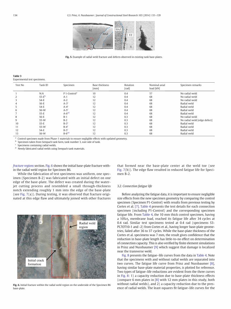
ii.
iii.
ii. iii.
FZHAZ
BM
HAZ
FZ
Fig. 5. Example of radial weld fracture and defects observed in existing tank base-plates.
Table 3Experimental test specimens.
Test No Tank ID Specimen Base thickness[mm]
Rotation[rad]
Nominal axialload [kN]
Specimen remarks
1 N/A P 1-Controla 10 0.4 57 No radial weld2 S5-Eb A-1 12 0.4 68 No radial weld3 S4-E A-2 12 0.4 68 No radial weld4 S6-E A-3c 12 0.4 68 Radial weld5 S4-E A-4c 12 0.4 68 Radial weld6 S6-W A-5c 12 0.4 68 Radial weld7 S5-E A-6cd 12 0.4 68 Radial weld8 S6-E B-1 12 0.3 68 No radial weld9 S5-W B-2 12 0.3 68 No radial weld [edge defect]10 S5-E B-3c 12 0.3 68 Radial weld11 S5-W B-4c 12 0.3 68 Radial weld12 S4-E B-5c 12 0.3 68 Radial weld13 S6-W B-6cd 12 0.3 68 Radial weld
a Control specimen made from Phase-1 materials to ensure negligible effects with updated geometry.b Specimen taken from Sempach tank farm, tank number 3, east side of tank.c Specimens containing radial welds.d Newly fabricated radial welds using Sempach tank materials.
134 G.S. Prinz, A. Nussbaumer / Journal of Constructional Steel Research 103 (2014) 131–139
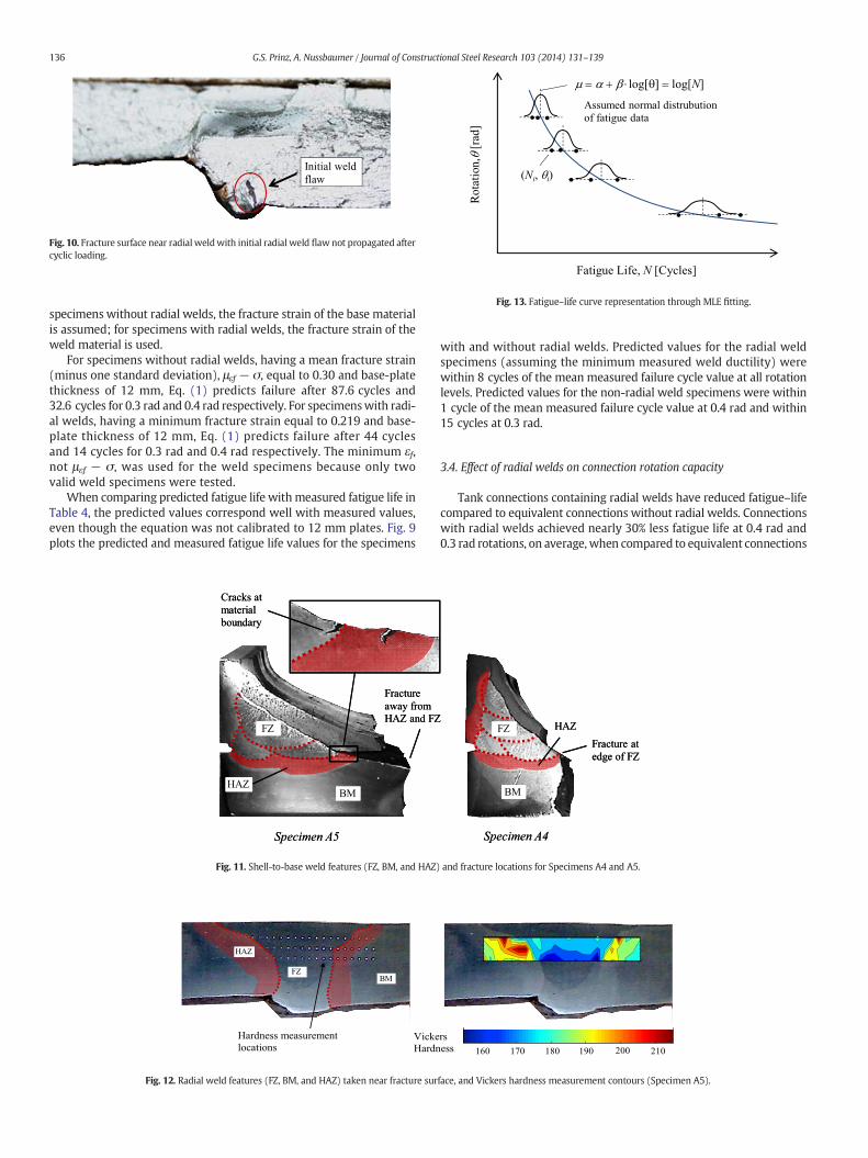
fracture regions section. Fig. 6 shows the initial base-plate fracture with-in the radial weld region for Specimen B6.
While the fabrication of test specimens was uniform, one spec-imen (Specimen B-2) was fabricated with an initial defect on oneedge of the base-plate. The defect was created during the water-jet cutting process and resembled a small through-thicknessnotch extending roughly 1 mm into the edge of the base-plate(see Fig. 7(a)). During testing, it was observed that fracture origi-nated at this edge flaw and ultimately joined with other fractures
Radial weld region
Initial crack formation
Fig. 6. Initial fracture within the radial weld region on the underside of the Specimen B6base-plate.
that formed near the base-plate center at the weld toe (seeFig. 7(b)). The edge flaw resulted in reduced fatigue life for Speci-men B-2.
3.2. Connection fatigue life
Before analyzing the fatigue data, it is important to ensure negligiblesize effects from the new specimen geometry by comparing the controlspecimen (Specimen P1-Control) with results from previous testing byCortes et al. [7]. Table 4 presents the test details for each connectionspecimen (including P1-Control) and the corresponding specimenfatigue life. From Table 4, the 10 mm thick control specimen, havinga 10%σy membrane load, reached its fatigue life after 34 cycles at0.4 rad. Similar test specimens tested at 0.4 rad (specimens S3-PL7OT10-1 and -2) from Cortes et al., having longer base-plate geome-tries, failed after 36 to 37 cycles. While the base-plate thickness of theCortes et al. specimens was 7 mm, the result gives confidence that thereduction in base-plate length has little-to-no effect on determinationof connection capacity. This is also verified by finite element simulationsin Prinz and Nussbaumer [9] which suggest that damage is localizednear the transverse weld.
Fig. 8 presents the fatigue–life curves from the data in Table 4. Notethat the specimens with and without radial welds are separated intotwo curves. The fatigue life curve from Prinz and Nussbaumer [8],having similar base-plate material properties, is plotted for reference.Two types of fatigue–life reductions are evident from the three curvesin Fig. 8: 1) a capacity reduction due to base-plate thickness effects(compare 6 mm plates in [8] with 12 mm plates in this study, bothwithout radial welds), and 2) a capacity reduction due to the pres-ence of radial welds. The least-squares fit fatigue–life curves for the

Initial crack formationsThrough-thickness
notch defect
(b)(a)
Plastic corrosion coating on inside tank surface
Base-plateFracture path
Fig. 7. (a) Initial through-thickness notch defect from fabrication process and (b) final fracture surface.
Table 4Fatigue life values.
Test No Tank ID Specimen Base thickness[mm]
Rotation[rad]
Nominal axialload [kN]
Nf m
1 N/A P 1-Controla 10 0.4 57 34.0 –
2 S5-Eb A-1 12 0.4 68 33.1 33.33 S4-E A-2 12 0.4 68 33.44 S6-E A-3c 12 0.4 68 17.15 S4-E A-4c 12 0.4 68 18.1 22.76 S6-W A-5c 12 0.4 68 35.47 S5-E A-6cd 12 0.4 68 20.38 S6-E B-1 12 0.3 68 83.4 72.89 S5-W B-2 12 0.3 68 62.2e
10 S5-E B-3c 12 0.3 68 58.411 S5-W B-4c 12 0.3 68 50.0 51.512 S4-E B-5c 12 0.3 68 50.213 S6-W B-6cd 12 0.3 68 47.2
a Control specimen made from Phase-1 materials to ensure negligible effects with updated geometry.b Specimen taken from Sempach tank farm, tank number 3, east side of tank.c Specimens containing radial welds.d Newly fabricated radial welds using Sempach tank materials.e Fracture initiated from a small notch defect on the plate edge and progressed toward cracks forming at the plate center.
135G.S. Prinz, A. Nussbaumer / Journal of Constructional Steel Research 103 (2014) 131–139
specimens with and without radial welds are Nfψ = 0.652/θ3.72 and
Nf = 0.433/θ2.88 respectively.
3.3. Predictive capability of the Prinz–Nussbaumer fatigue–life equation
An equation for predicting the fatigue life of tank shell-to-base con-nections was proposed in [8], dependent only on the applied rotationrange and material fracture strain. The equation, presented again inEq. (1), incorporates a knock-down factor for plates thicker than6 mm based on limited testing of 10 mm and 8 mm plates. Because
0
0.1
0.2
0.3
0.4
0.5
100010010
Rot
atio
n, θ
[rad
]
Fatigue Life [Cycles]
No radial weld
Radial weld
Prinz and Nussbaumer [8] curve (6mm)
Weld effect
Thickness effect
Fig. 8. Fatigue–life curves for 12 mm test specimens and 6 mm specimens from [8].
the equation has not been used to evaluate plates thicker than 10 mm,it is worthwhile to compare the predictive capability of Eq. (1) withthe 12 mm specimens tested in this study.
Nf ¼ 1:6− ttref
!� 555 � ε4:2f � θγ : ð1Þ
In Eq. (1), t is the base-plate thickness inmillimeters, tref is the refer-ence base-plate thickness equal to 10mm, and γ is an exponential func-tion dependent on fracture strain equal to γ = −1.97εf −0.46. For
0
0.1
0.2
0.3
0.4
0.5
000100101
Rot
atio
n, θ
[rad
]
Fatigue Life [Cycles]
No radial weld
Radial weld
Fatigue-life predictions
Fig. 9. Predicted versusmeasured fatigue–life for specimenswith andwithout radial base-plate welds.
Initial weld flaw
Fig. 10. Fracture surface near radial weldwith initial radial weld flawnot propagated aftercyclic loading.
Rota
tion,
θ[r
ad]
Fatigue Life, N [Cycles]
μ = α + β log[θ] = log[N].
Assumed normal distrubution of fatigue data
(Ni, θi)
Fig. 13. Fatigue–life curve representation through MLE fitting.
136 G.S. Prinz, A. Nussbaumer / Journal of Constructional Steel Research 103 (2014) 131–139
specimens without radial welds, the fracture strain of the base materialis assumed; for specimens with radial welds, the fracture strain of theweld material is used.
For specimens without radial welds, having a mean fracture strain(minus one standard deviation), μεf − σ, equal to 0.30 and base-platethickness of 12 mm, Eq. (1) predicts failure after 87.6 cycles and32.6 cycles for 0.3 rad and 0.4 rad respectively. For specimenswith radi-al welds, having a minimum fracture strain equal to 0.219 and base-plate thickness of 12 mm, Eq. (1) predicts failure after 44 cyclesand 14 cycles for 0.3 rad and 0.4 rad respectively. The minimum εf,not μεf − σ, was used for the weld specimens because only twovalid weld specimens were tested.
When comparing predicted fatigue life withmeasured fatigue life inTable 4, the predicted values correspond well with measured values,even though the equation was not calibrated to 12 mm plates. Fig. 9plots the predicted and measured fatigue life values for the specimens
FZ
BMHAZ
Specimen A5
Fracture away from HAZ and FZ
Cracks at material boundary
FZ
BMHAZ
Specimen A5
Fracture away from HAZ and FZ
Cracks at material boundary
Fig. 11. Shell-to-base weld features (FZ, BM, and HAZ)
VickeHardn
FZBM
Hardness measurement locations
HAZ
Fig. 12. Radial weld features (FZ, BM, and HAZ) taken near fracture sur
with and without radial welds. Predicted values for the radial weldspecimens (assuming the minimum measured weld ductility) werewithin 8 cycles of the mean measured failure cycle value at all rotationlevels. Predicted values for the non-radial weld specimens were within1 cycle of the mean measured failure cycle value at 0.4 rad and within15 cycles at 0.3 rad.
3.4. Effect of radial welds on connection rotation capacity
Tank connections containing radial welds have reduced fatigue–lifecompared to equivalent connections without radial welds. Connectionswith radial welds achieved nearly 30% less fatigue life at 0.4 rad and0.3 rad rotations, on average,when compared to equivalent connections
FZ
BM
HAZFracture at edge of FZ
Specimen A4
FZ
BM
HAZFracture at edge of FZ
Specimen A4
and fracture locations for Specimens A4 and A5.
0 2 4 6 8 10 12 14 16 18 20 22-3
-2.5
-2
-1.5
-1
-0.5
0
160 170 180 190 200 210rsess
face, and Vickers hardness measurement contours (Specimen A5).

Table 5Fatigue test data from Cortes et al. [7], Prinz and Nussbaumer [8], and the current study.
θ [rad] Material grade N μ
Cortes et al. [7] (t = 6 mm)0.4 S355 22.1 22.60.4 S355 23.1
0.3 S355 96.5 92.90.3 S355 89.3
0.2 S355 430 420.50.2 S355 411
Prinz and Nussbaumer [8] (t = 6 mm)0.5 S355 59 64.20.5 S355 670.5 S355 730.5 S355 600.5 S355 62
0.4 S355 132 1370.4 S355 1250.4 S355 154
0.3 S355 306 293.30.3 S355 3100.3 S355 264
Current study (t = 12 mm)0.4a S355 34 –
0.4b S355 17.1 22.70.4b S355 18.10.4b S355 35.40.4b S355 20.3
0.4 S355 33.1 33.30.4 S355 33.5
0.3b S355 58.4 51.50.3b S355 50.00.3b S355 50.20.3b S355 47.2
0.3 S355 83.4 72.80.3 S355 62.2
a Geometry control specimen (t = 10 mm) from Phase-1 testing (N value neglectedfrom fatigue–life curves).
b Specimens containing radial welds.
Table 6Proposed fatigue–life curve parameters obtained from MLE.
α β
Phase-1 −0.216 −3.89Phase-2 2.26 −2.85Phase-3 2.76 −2.72Phase-3a 1.68 −2.84
a Specimens with radial welds.
137G.S. Prinz, A. Nussbaumer / Journal of Constructional Steel Research 103 (2014) 131–139
without radial welds. This reduction in fatigue life can be directly asso-ciated with a ductility decrease in the weld and weld-HAZ of the radialweld region. Given only the lower ductility of the weldmetal comparedwith the base metal, Eq. (1) (calibrated for connections without radialwelds)was able to reasonably predict the fatigue–life of specimens hav-ing radial welds.
Even with nearly 30% reduction in fatigue–life, the capacity of allconnections having radial welds far exceeded the current Eurocode0.2 rad rotation limit. The lowest measured connection capacity, corre-sponding to a 12mmbase-plate containing a radial weld, achieved over17 cycles at 0.4 rad prior to connection failure. Additionally, using theverified Eq. (1), and considering a 12 mm base-plate with the codelower-bound ductility requirement of 0.15, the connection would stillbe expected to achieve nearly 6 cycles at 0.4 rad of rotation.
3.5. Influence of initial weld flaws on damage evolution
Initial fractures and flaws originating near the root of the radialwelds appear to have negligible influence on the rotation capacity ofthe tank connections. Running parallel to the radial welds (perpendicu-lar to the critical fracture), such fractures and flaws do not appear toprogress through the base-plate thickness during cyclic loading (seeFig. 10).
3.6. Metallographic analysis near transverse and radial weld fractureregions
Critical fracture locations for the tank specimens varied between thetransverse weld toe and several millimeters away from the transverseweld toe. Fig. 11 shows polished transverse weld regions for SpecimenA4 (having fractured at the weld toe) and Specimen A5 (having frac-tured away from the weld toe and weld HAZ). While several smallercracks are observable at the weld toe of Specimen A5, the critical crackforms several millimeters away, outside the HAZ (identified in Fig. 11through metallographic analysis). It is still unclear what causes somespecimens to fail away from the weld toe, however preliminary testsconducted on T-joint specimens having homogenous material proper-ties and machined weld geometries suggest that the weld materialand HAZ play a role. A preliminary T-joint test, having a machinedweld geometry and homogeneous material properties, failed at theweld toe (near the geometric stress riser) matching predictions fromfinite element models in [9].
Fig. 12 shows a section of radial weld taken from Specimen A5. InFig. 12, the various weld material zones are identified (FZ, BM, andHAZ) and hardness contours are plotted across the different regions.As expected, the hardness varies across the radial weld region, withthe hardness in the HAZ outside the FZ being higher, indicating lowerductility. This HAZ for the radial welds runs perpendicular to the criticalcrack path and extends the entire length of the base-plate, creating aregion of lower ductility for ULCF cracks to originate. This somewhatexplains the observation that specimens with radial welds fail soonerthan specimens without radial welds.
3.7. Alternative creation of fatigue–life curves using maximum likelihoodestimation
In the previous studies [7,8], and in the previous sections of thispaper, fatigue–life curves are created using a simplified least-squaresfitting procedure, minimizing the error between each data point andthe regression line. In this section, an alternative curve creation ap-proach is compared wherein an advanced statistical method calledmaximum likelihood estimation (MLE) is used to create fatigue–lifecurves thatmaximize the observed sample joint probability. The follow-ing paragraphs describe theMLEmethod and apply it to the tank fatiguedata from this study (alongwith data from the previous tank studies [7,8]). Comparisons are made between the fatigue–life curves generated
by least-squares fitting and MLE fitting and updates are given on tankconnection rotation capacity.
3.8. Overview and application of the MLE method
The MLE method is summarized in four general steps: 1) propose amodel and set of parameters that represent the observed data; 2) calcu-late the probability of having failure at each data point given an as-sumed set distribution; 3) calculate the joint probability accountingfor all data points; and 4) determine the parameters from step 1 thatmaximize the joint probability of step 3.
Based on previous low-cycle fatigue studies [10,11], a power–lawrelationship is assumed for each fatigue data set, given by Eq. (2):
logNf ¼ α þ β log θð Þ ð2Þ
138 G.S. Prinz, A. Nussbaumer / Journal of Constructional Steel Research 103 (2014) 131–139
whereN is the number of cycles to failure at a given applied constant ro-tation range, θ. Parameters α and β are unknown, to be determinedthrough theMLE procedure. Fig. 13 shows theMLE basedmodel assum-ing the above power–law relationship and considering N as a normallydistributed random variable at each rotation level.
The probability of having failure at each data point (Ni, θi) in Fig. 13,assuming the data at each rotation level is normally distributed, is givenby the probability density function:
f Ni¼ PDFNi ;θi ¼
1ffiffiffiffiffiffiffiffiffiffiffiffiffi2π � σ
p� �
exp−12σ2 � Ni−eα θið Þβ
h i2� �: ð3Þ
In Eq. (3), the standard deviation is assumed to vary by stress level(σ = C / θ) to account for an assumed linear increase in fatigue datascatter with decreased rotation range. This linear increase in σ isbased on the failures of 6 mm S355 base-plates loaded at 0.3, 0.4, and0.5 rad in [8].
The goal of theMLE is tomaximize the joint probability of predictingfailure at all points (or in other words, to maximize the likelihood ofpredicting failure at all points). This joint failure probability (or likeli-hood) is simply the product of every data-point failure probability,written as:
L ¼ ∏n
i¼1f Ni
ð4Þ
where, L, fNi, and n are the likelihood, probability of predicting failure atan individual data point (i), and the total number of data-points respec-tively. A nonlinear generalized reduced gradient optimization algorithmis used to maximize the likelihood given by the above MLE procedure.
Table 5 shows the sample fatigue data from each study and Table 6shows the resulting optimized fatigue–life curve parameters (α, β)determined from MLE (to be used in Eq. (2)).
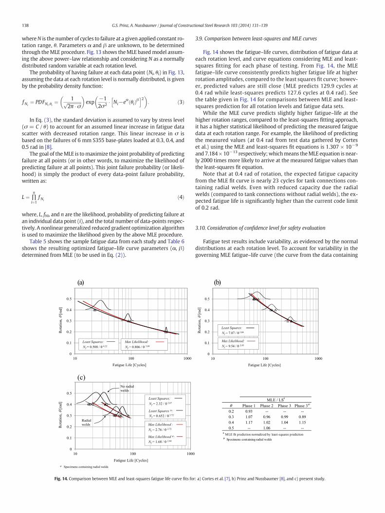
0
0.1
0.2
0.3
0.4
0.5
000100101
Rota
tion,
θ[r
ad]
Fatigue Life [Cycles]
Least Squares:Nf = 0.508 / θ 4.22
Max Likelihood:Nf = 0.806 / θ 3.89
)a(
0
0.1
0.2
0.3
0.4
0.5
0.6
000100101
Rota
tion,
θ[r
ad]
Fatigue Life [Cycles]
Least Squares:Nf = 2.32 / θ 2.87
Max Likelihood :Nf = 2.76 / θ 2.72
Max Likelihood ψ:Nf = 1.68 / θ 2.84
ψ Specimens containing radial welds
No radial welds
Radial welds
Least Squares ψ:Nf = 0.652 / θ 3.72
(c)
Fig. 14. Comparison between MLE and least-squares fatigue life curve fits for
3.9. Comparison between least-squares and MLE curves
Fig. 14 shows the fatigue–life curves, distribution of fatigue data ateach rotation level, and curve equations considering MLE and least-squares fitting for each phase of testing. From Fig. 14, the MLEfatigue–life curve consistently predicts higher fatigue life at higherrotation amplitudes, compared to the least squares fit curve; howev-er, predicted values are still close (MLE predicts 129.9 cycles at0.4 rad while least-squares predicts 127.6 cycles at 0.4 rad). Seethe table given in Fig. 14 for comparisons between MLE and least-squares prediction for all rotation levels and fatigue data sets.
While the MLE curve predicts slightly higher fatigue–life at thehigher rotation ranges, compared to the least-squares fitting approach,it has a higher statistical likelihood of predicting the measured fatiguedata at each rotation range. For example, the likelihood of predictingthe measured values (at 0.4 rad from test data gathered by Corteset al.) using the MLE and least-squares fit equations is 1.307 × 10⁻⁹
and 7.184× 10⁻¹³ respectively;whichmeans theMLE equation is near-ly 2000 times more likely to arrive at the measured fatigue values thanthe least-squares fit equation.
Note that at 0.4 rad of rotation, the expected fatigue capacityfrom the MLE fit curve is nearly 23 cycles for tank connections con-taining radial welds. Even with reduced capacity due the radialwelds (compared to tank connections without radial welds), the ex-pected fatigue life is significantly higher than the current code limitof 0.2 rad.
3.10. Consideration of confidence level for safety evaluation
Fatigue test results include variability, as evidenced by the normaldistributions at each rotation level. To account for variability in thegoverning MLE fatigue–life curve (the curve from the data containing
0
0.1
0.2
0.3
0.4
0.5
0.6
000100101
Rot
atio
n, θ
[rad
]
Fatigue Life [Cycles]
Least Squares:Nf = 7.87 / θ 3.04
Max Likelihood:Nf = 9.54 / θ 2.85
)b(
θ Phase 1 Phase 2 Phase 3 Phase 3ψ
0.2 0.93 -- -- --0.3 1.07 0.96 0.99 0.890.4 1.17 1.02 1.04 1.150.5 -- 1.06 -- --
a MLE fit prediction normalized by least-squares predictionψ Specimens containing radial welds
MLE / LSa
: a) Cortes et al. [7], b) Prinz and Nussbaumer [8], and c) present study.

0
0.1
0.2
0.3
0.4
0.5
00100101 0
Rot
atio
n, θ
[rad
]
Fatigue Life [Cycles]
Radialweld data95 %
confidence level
Fig. 15. 95% confidence level curve fromMLE curve (test data containing radial base-platewelds).
139G.S. Prinz, A. Nussbaumer / Journal of Constructional Steel Research 103 (2014) 131–139
radial welds) a lower-bound 95% confidence level is adopted to providesafety in the determination of fatigue life for welded tank connections.Fig. 15 shows the MLE curve representing a 50% failure probability andthe shifted MLE curve representing the lower-bound 95% confidencelevel. From the lower-bound curve in Fig. 15, the shell-to-base connec-tions having a 12mmbase-plate and radial welds would still withstandnearly 12 cycles at 0.4 rad of rotation. This suggests that the currentcode limit is overly conservative in its value of 0.2 rad.
4. Summary and conclusions
Twelve tank shell-to-base connections, with and without radialwelds in the base-plate, were tested under constant amplitude rotationcycles to determine the low-cycle fatigue performance. All connectionspecimens were taken from existing tanks within Switzerland, havinga 12 mm base-plate thickness and 160 mm base-plate width. Appliedrotation ranges of 0.3 rad and 0.4 rad were chosen to investigate de-mands greater than current Eurocode limits. Biaxial loading (simulta-neous application of base-plate tension and rotation) was used tosimulate realistic tank demands such as base-plate membrane actionduring uplift. Statistical analyses were performed on the new fatiguetest data and data from previous studies.
The following conclusions are based on the cyclic testing of thetwelve tank connections with and without radial welds in the base-plate. Experimental testing indicates:
1) Tank base-plate sections containing radial welds govern the shell-to-base rotation capacity during uplift. The rotation capacity (fatiguelife) of tank shell-to-base connections containing radial welds wasnearly 30% lower (on average) than equivalent connections withoutradial welds.
2) Even though capacity is reduced for connectionshaving radialwelds,the available capacity is still far greater than current code limits.Using the fatigue–life curve generated by maximizing the experi-mental sample likelihood (shifted by 2σ to represent the lower-bound 95% confidence level), connections with radial welds couldbe expected to withstand nearly 12 cycles at 0.4 rad of rotation(two times the current Eurocode limit). From Cortes et al. [12], thelargest expected cyclic demand for Switzerland (normalized bypeak rotation) is 4 cycles and the current code limit appears overlyconservative.
3) Initial radialweld defects (originating near theweld root, against thebackingbar) appear to have little-to-no effect on connection rotationcapacity. Such flaws or defects run perpendicular to the critical crackand were not observed to propagate through the thickness duringtesting.
4) The fatigue life equation proposed by Prinz and Nussbaumer [8] canreasonably predict the performance of base-plate connections hav-ing radial welds, given the ductility of the material within the weldregion. Additionally, the equation reduction factor for plates thickerthan 6 mm appears to be reasonable for the 12 mm plates in thisstudy. Given this predictability, and considering the lower-boundductility permissible in the current standards (εf = 0.15), a 12 mmplate at 0.4 rad of rotation could be expected to achieve nearly6 cycles before fatigue failure.
References
[1] Peek R. Analysis of unanchored liquid storage tanks under lateral loads. Earthq EngStruct Dyn 1988;16:1087–100.
[2] Malhotra PK, Veletsos AS, Tang HT. Seismic response of unanchored liquid storagetanks. Proc. Structural Mechanics in Reactor Technology Conference (SMiRT-12).Suttgart, Germany. Paper No. SD103/101; 1993.
[3] Peek R, Jennings PC. Simplified analysis of unanchored tanks. Earthq Eng Struct Dyn1988;16:1073–85.
[4] Malhotra PK, Veletsos AS. Uplifting analysis of base plates in cylindrical tanks.J Struct Eng 1994;120(12):3489–505.
[5] Fujikazu S, Akira I, Hajime H, Yukio M. Experimental study on uplifting behavior offlat-based liquid storage tanks without anchors. Proc. 9th World Conference onEarthquake Engineering., Tokyo–Kyoto, Japan; 1988. p. 649–54.
[6] Eurocode_8. Part 4: silos, tanks, and pipelines. ENV 1998-4. Brussels, Belgium:European Committee for Standardization; 1998.
[7] Cortes G, Nussbaumer A, Berger C, Lattion E. Experimental determination of therotational capacity of wall-to-base connections in storage tanks. J Constr Steel Res2011;67(2011):1174–84.
[8] Prinz GS, Nussbaumer A. On the low-cycle fatigue capacity of unanchored steelliquid storage-tank shell-to-base connections. Bull Earthq Eng 2012;10(6):1943–58.
[9] Prinz GS, Nussbaumer A. Fatigue analysis of liquid-storage tank shell-to-base con-nections under multi-axial loading. Eng Struct 2012;40:75–82.
[10] Coffin Jr LF. A study of the effects of cyclic thermal stresses in ductile metals. ASME1954;76:931–50.
[11] Manson SS. Behavior of materials under conditions of thermal stress. Technical note2933. Tennessee (USA): National Advisory Committee for Aeronautics; 1954.
[12] Cortes G, Prinz GS, Nussbaumer A, Koller M. Cyclic demand at the shell-bottomconnection of unanchored steel tanks. 15th World Conference on Earthquake Engi-neering. Lisbon, Portugal. Paper No. 1115; 2012.


