Effect of Cutout on the Ultimate Strength of a Wind ... Selcuk Sahin... · Effect of Cutout on the...
23
International Conference on Ships and Offshore Structures ICSOS 2016 31 August – 2 September 2016, Hamburg, Germany Effect of Cutout on the Ultimate Strength of a Wind Turbine Tower Sang Eui Lee a , Selcuk Sahin b,c , Philippe Rigo b , Minsue Park d , Jeom Kee Paik a,d,e,*1 a The Korea Ship and Offshore Research Institute (The Lloyd’s Register Foundation Research Centre of Excellence), Pusan National University, Busan 46241, Republic of Korea b Naval Architecture and Transport Systems Department (LHCN), University of Liège, 6 Quai Banning, B4000 Liège, Belgium c Laboratoire d’Hydrodynamique, Energétique et Environement Atmosphérique (LHEEA), Ecole Centrale de Nantes, 44321 Nantes, France d Department of Naval Architecture and Ocean Engineering, Pusan National University, Busan 46241, Republic of Korea e Department of Mechanical Engineering, University College London, Torrington Place, London WC1E 7JE, UK Abstract In wind turbine structures, cutouts are often located to make a way of access or passage. These perforations will reduce the ultimate strength of a wind turbine tower. The cutouts may thus need to be included in the ultimate strength formulations as a parameter of influence where significant. The aims of this study are to examine the effect of cutout on the ultimate-strength characteristics of the wind turbine tower, and to propose some practical design formulae to predict the ultimate strength. The structural features of the cutout and the tower in real wind turbines are investigated. The effect of different design variables, such as shape, location, aspect ratio, column slenderness ratio and column aspect ratio on the ultimate-strength behavior is described. The tower ultimate strengths are computed by elastic-plastic large-deflection finite element analyses. Thus, practical design formulae accommodating whole range of actual dimensional characteristics of the cutout and the tower have been derived and proposed. The findings of the research and the proposed design formulae have the potential to enhance the structural design and safety assessment of the wind turbine tower. Keywords: Cutout; ultimate strength; wind turbine tower; parameters of influence; nonlinear finite element method. 1. Introduction In steel-plated structures, cutouts are widely used to provide a way of access or to lighten the structure. It is no wonder that these perforations will reduce not only the buckling strength of structures but also the ultimate strength. In particular, a wind turbine which has relatively large size of a door will be exposed to considerable strength reduction that can potentially cause significant structural failure in the wind turbine tower. It is thus of great importance to develop advanced technologies which can predict the reduced strength of the tower by the size of the cutout. The regulations for a reliable design and safety of wind turbines have been developed and recommended by various authorities (ECCS 1980, DIN 18800-4 1990, EN1993-1.6 2006, DNVGL 2013a and DNVGL 2013b). However, no detailed guidelines for predicting the reduced strength of towers are available. It is noted that useful research attempts to investigate the effect of cutout on structural capacity of the wind turbine tower are relatively far less than plates (Sabir and Chow 1983, Brown and Yettram 1986, Azizian and Roberts 1983, Shangmugam et al. 1999, Durban and Zuckerman 1999, Betten and Shin 2000, El-Sawy et al. 2004, Paik 2007, Kim et al. 2009 and Wang et al. 2009). For a couple of decades, there were a number of researches related to buckling analysis of circular cylindrical shells(Brazier 1927, Reissner 1961, Seide and Weingarten 1961, Fabian 1977 and Gellin 1980) with the cutout under axial compression (Schenk and Schuёller 2007, Shariati and Rokhi 2010 and Ghazijahani * Corresponding author. Tel.: +82-51-510-2429; fax: +82-51-518-7687. E-mail address: [email protected]
Transcript of Effect of Cutout on the Ultimate Strength of a Wind ... Selcuk Sahin... · Effect of Cutout on the...

International Conference on Ships and Offshore Structures
ICSOS 2016
31 August – 2 September 2016, Hamburg, Germany
Effect of Cutout on the Ultimate Strength of a Wind Turbine Tower
Sang Eui Leea, Selcuk Sahin
b,c, Philippe Rigo
b, Minsue Park
d, Jeom Kee Paik
a,d,e,*1
aThe Korea Ship and Offshore Research Institute (The Lloyd’s Register Foundation Research Centre of Excellence), Pusan
National University, Busan 46241, Republic of Korea bNaval Architecture and Transport Systems Department (LHCN), University of Liège, 6 Quai Banning, B4000 Liège, Belgium
cLaboratoire d’Hydrodynamique, Energétique et Environement Atmosphérique (LHEEA), Ecole Centrale de Nantes, 44321
Nantes, France dDepartment of Naval Architecture and Ocean Engineering, Pusan National University, Busan 46241, Republic of Korea
eDepartment of Mechanical Engineering, University College London, Torrington Place, London WC1E 7JE, UK
Abstract
In wind turbine structures, cutouts are often located to make a way of access or passage. These perforations will
reduce the ultimate strength of a wind turbine tower. The cutouts may thus need to be included in the ultimate
strength formulations as a parameter of influence where significant. The aims of this study are to examine the
effect of cutout on the ultimate-strength characteristics of the wind turbine tower, and to propose some practical
design formulae to predict the ultimate strength. The structural features of the cutout and the tower in real wind
turbines are investigated. The effect of different design variables, such as shape, location, aspect ratio, column
slenderness ratio and column aspect ratio on the ultimate-strength behavior is described. The tower ultimate
strengths are computed by elastic-plastic large-deflection finite element analyses. Thus, practical design formulae
accommodating whole range of actual dimensional characteristics of the cutout and the tower have been derived
and proposed. The findings of the research and the proposed design formulae have the potential to enhance the
structural design and safety assessment of the wind turbine tower.
Keywords: Cutout; ultimate strength; wind turbine tower; parameters of influence; nonlinear finite element method.
1. Introduction
In steel-plated structures, cutouts are widely used to provide a way of access or to lighten the
structure. It is no wonder that these perforations will reduce not only the buckling strength of structures
but also the ultimate strength. In particular, a wind turbine which has relatively large size of a door will
be exposed to considerable strength reduction that can potentially cause significant structural failure in
the wind turbine tower. It is thus of great importance to develop advanced technologies which can
predict the reduced strength of the tower by the size of the cutout.
The regulations for a reliable design and safety of wind turbines have been developed and
recommended by various authorities (ECCS 1980, DIN 18800-4 1990, EN1993-1.6 2006, DNVGL
2013a and DNVGL 2013b). However, no detailed guidelines for predicting the reduced strength of
towers are available.
It is noted that useful research attempts to investigate the effect of cutout on structural capacity of
the wind turbine tower are relatively far less than plates (Sabir and Chow 1983, Brown and Yettram
1986, Azizian and Roberts 1983, Shangmugam et al. 1999, Durban and Zuckerman 1999, Betten and
Shin 2000, El-Sawy et al. 2004, Paik 2007, Kim et al. 2009 and Wang et al. 2009). For a couple of
decades, there were a number of researches related to buckling analysis of circular cylindrical
shells(Brazier 1927, Reissner 1961, Seide and Weingarten 1961, Fabian 1977 and Gellin 1980) with the
cutout under axial compression (Schenk and Schuёller 2007, Shariati and Rokhi 2010 and Ghazijahani
* Corresponding author. Tel.: +82-51-510-2429; fax: +82-51-518-7687.
E-mail address: [email protected]

Nomenclature
A Area of the cutout b Breadth of the cutout
D ( maxD / minD ) Diameter (maximum/minimum) of the wind turbine tower
E Elastic modulus of the material RF Reference force of the wind turbine tower
TowerF Force acting on the wind turbine tower uF Ultimate force of the wind turbine tower
windF Thrust induced by blades zF Load in z-axis
h Height of the cutout
oh Distance from the lower end to the centre of the cutout
H Height of the wind turbine tower SH Height of 1st section
M Pure bending moment uM Ultimate bending moment
PM Plastic bending moment yM Pure bending moment in y-axis
r Radius R Corner radius of the cutout 2R Adjusted R-square
t ( maxt / mint ) Thickness (maximum/minimum) of the wind turbine tower
ct Thickness of the cutout T Torque moment
, ,x y zu u u Translational restraints in the x-, y- and z-axis
ow Initial imperfection W Weight
Aspect ratio (height to breadth) of the cutout
Slenderness ratio (breadth to thickness) of the cutout
max Maximum deformation
Column aspect ratio (height to diameter) of the wind turbine tower
max / min Maximum/minimum column aspect ratio (height to maximum/minimum diameter) of the
wind turbine tower
Column slenderness ratio (diameter to thickness) of the wind turbine tower
max / min Maximum/minimum column slenderness ratio (maximum/minimum diameter to
maximum/minimum thickness) of the wind turbine tower
Poisson’s ratio
Angle of the cutout in the circumferential direction
, ,x y z Rotational restraint in the x-, y- and z-axis
Coefficient of correlation Y Yield stress of the material
, , , ,D t h b C Coefficients of design formula for axial compression
, , , ,D t h b C Coefficients of design formula for pure bending
et al. 2015) and pure bending (Yeh et al. 1999, Dimopoulos and Gantes 2012, 2013, 2015 Guo et al.
2013 and Dimopoulos et al. 2015).
The aims of this study are to use nonlinear finite element analysis to examine the effect of cutout on
ultimate-strength characteristics and to propose simple design formula to estimate the reduced ultimate
strength of the wind turbine tower under axial compression and pure bending. The structural features of
wind turbines are investigated using data collected from 102 existing wind turbines in service. Finite
element modelling techniques are developed to calculate the ultimate-strength behavior of the tower
with a variety of design variables, such as cutout’s shape and location, aspect ratio, column slenderness
ratio and column aspect ratio. The validation of developed nonlinear finite element method modelling is
conducted. For parametric series analyses, design of experiment (DOE) method such as central
composite design (CCD) is applied. Numerical computations are used to derive a plausible design
formula that predicts the ultimate strength of the tower.
2. Literature Review
In the early days, the buckling analysis of circular cylindrical shells analytically and experimentally
involved. In particular, Brazier (1927) noted that the ultimate strength is directly related to the
ovalization of the tube cross-section under bending and derived an expression for the strain energy per
unit tube length in terms of the change in axial curvature. Reissner (1961) further developed the more
general formulation for thin-walled cylindrical shells of arbitrary cross section. By using a modified
Donnell equation and the Galerkin method, Seide and Weingarten (1961) found out that the maximum
elastic bending buckling stress is equal to the critical compressive stress under axial compression.
Sherman (1976) experimentally identified that shells with column slenderness ratio, greater than
about 50 do not have sufficient plastic hinge rotation capacity to develop the classical ultimate strength.
Fabian (1977) observed two modes of failure of infinitely long cylindrical elastic shells subjected to
bending, pressure and axial loads; the circumferential flattening constituting an ultimate load and
compression wrinkles generating bifurcation buckling axially. Gellin (1980) demonstrated the example
of extending the results of Brazier (1927) into the plastic range and confirmed the results of limit states
observed by Fabian (1977).
Traditionally, experimental tests have been regarded as the most efficient way of obtaining technical
solutions despite its high costs. Over the past 50 years, computing speeds and capabilities of numerical
tools have been significantly enhanced. Hence, a contribution of numerical simulations to the
engineering applications is higher than before. The same trend observed in wind turbine industries and
a number of experiment tests and numerical simulations have been extensively carried out to examine
the load carrying capacity of circular cylindrical shells with a cutout under axial compression and pure
bending.
For axial compression, Tennyson (1968) experimentally observed a membrane stress distribution
and isoclinic patterns around the edge of the cutout by using photo-elastic shells. Jullien and Limamto
(1998) found that the buckling strength is sensitive to the cutout angle or circumferential size based on
parametric studies of the shape (square, rectangular, circular), the dimensions (axial and circumferential
sizes, diameter) of the cutout, furthermore, he pointed out the importance of initial imperfections for
numerical simulations. Schenk and Schuёller (2007) studied the effect of random geometric
imperfections on the critical load of thin-walled cylindrical shells under axial compression with
rectangular cutouts and found that the coefficient of variation of the critical load does not decrease with
decreasing the imperfections magnitude. Han et al. (2006) observed that the location and the size of the
cutout significantly affect the buckling load. Namely, cutouts located near the loaded end could
effectively absorb energy, and redistribute the load more efficiently. Shariati and Rokhi (2008, 2010),
reported that longer shells show much more sensitive to the position of the cutout. Moreover, they
observed that the buckling strength decreases as height increases with the constant cutout width.
Ghanbari Ghazijahani et al. (2015) experimentally found a symmetric ring-shaped bulging wave in the
intact specimen after initiation of the buckling. It was observed that the effect of the cutout height on
the capacity reveals less than 5% under axial compression.
For pure bending, Kyriakides and Ju (1992) and Ju and Kyriakides (1992) observed that thinner
shells develop short wavelength periodic ripples on the compressed side of the shell, and the shells
buckled locally and collapsed soon after the appearance of the ripples. On the other hand, thicker shells
were found to exhibit limit load instability as a direct consequence of the ovalization of the shell
cross-section caused by pure bending. Yeh et al. (1999) observed that for a shell with the circular
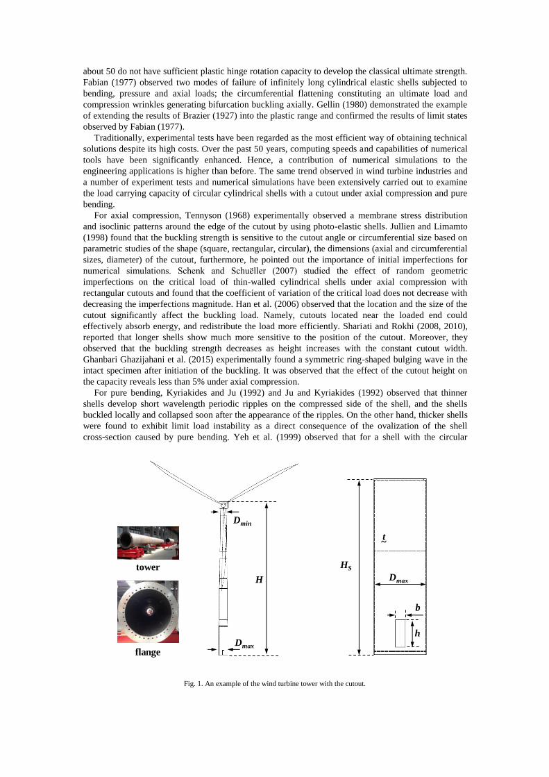
Fig. 1. An example of the wind turbine tower with the cutout.
Dmax
h
b
HS
t~
H
Dmin
Dmaxflange
tower

cutout, the ultimate strength is decreased as the diameter of the cutout increases; for a shell with a
rectangular cutout, the ultimate strength is decreased on increasing the size of the cutout. It was also
found that the ultimate strength of a shell with the cutout on compression side is smaller than for the
cutout on the tension side and the ultimate strength increased when the cutout is close to the end of the
clamped shell. Guo et al. (2013) found that with the increase of /D t ratio, the local buckling
phenomenon became more pronounced and the stiffeners increased the load carrying capacity and
improved the ductility as well.
The most distinguished numerical and experimental works are Dimopoulous׳s series of studies
(Dimopoulos and Gantes 2012, Dimopoulos and Gantes 2013, Dimopoulos and Gantes 2015 and
Dimopoulos et al. 2015) for circular cylindrical shell structures. Through experimental and numerical
studies of the buckling behavior for cantilevered circular cylindrical shells with the cutout and
stiffening were conducted. It was confirmed that the presence of the cutout leads to a strength reduction
and the lowest collapse load appears when the cutout is situated on the compression side (Dimopoulos
and Gantes 2012). Furthermore, it was found that simple stiffening types consisting of either a
peripheral frame or two longitudinal stiffeners with a ring are particularly efficient and can be used
instead of more complex ones (Dimopoulos and Gantes 2013). It was pointed out that the importance of
geometrical and material nonlinearities including initial imperfections (Dimopoulos and Gantes 2015).
At last, an assessment of stiffening effect of the cutout on circular cylindrical shells under dynamic
wind loading was conducted by using aero-elastic code. It was concluded that the dynamic effect leads
to a small decrease of tower strength compared to the one obtained via static analysis, but this reduction
was less than 10% in all investigated cases (Dimopoulos et al. 2015).
3. Structural Features of the Wind Turbine Tower and the Cutout
3.1. Definition of geometrical parameters
Wind turbines typically consist of some of circular cylindrical shell sections which are connected
with each other by bolted flanges as shown in Fig. 1. The geometrical attributes of a typical wind
turbine tower with the cutout are defined. The following four parameters for wind turbine towers are
considered: (a) minimum column aspect ratio ( /min minH D ); (b) maximum column aspect ratio (
/max maxH D ); (c) minimum column slenderness ratio ( /min min minD t ); (d) maximum column
slenderness ratio ( /max max maxD t ). The other two parameters for the cutout are considered: (e) aspect
ratio ( /h b ); (f) slenderness ratio ( / cb t ).
3.2. Geometrical features
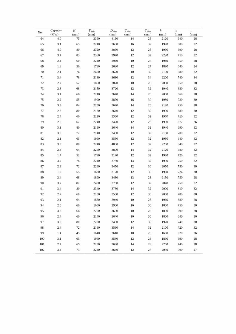
Data on 102 wind turbines and their cutouts are collected where the capacity range from 0.5 to 5.0
MW. The principal features are displayed in Appendix, Table A1. The geometrical characteristics of
each parameter predefined in Section 3.1 are then analyzed. The statistical distribution of the parameter
is shown in Figs. 2 and 3. Table 1 summarizes the range and most probable values of each parameter.
These findings are used to identify the geometrical parameters of the standard wind turbine tower and
the cutout, as follows: H = 65,000 mm, maxD = 3,750 mm, maxt = 30 mm, h = 1,900 mm, b = 700
mm and ct = 30 mm ( = 2.875, = 25.0). It was assumed that the standard wind turbine tower is
composed of four sections as shown in Fig. 4 and the height of 1st section which is used in the present
Table 1. Actual range and the most probable dimensions of the wind turbine and the cutout
Parameter Range Most probable Parameter Range Most probable
Capacity (MW) 0.5~5.0 2.5 maxt (mm) 16~40 30
H (mm) 37,000~100,000 65,000 min 17.5~42.1 30.0
h (mm) 1,640~2,900 1,900 max 12.0~27.7 19.0
b (mm) 620~1,100 700 min 100.0~250.0 170.0
ct (mm) 16~40 30.0 max 95.7~222.2 110.0
minD (mm) 1,600~3,000 2,300 2.2~3.8 2.875
maxD (mm) 2,610~6,000 3,750 19.1~43.8 25.0
mint (mm) 10~20 15

Fig. 2. Characteristics of the wind turbine tower and the cutout: (a) capacity; (b) height; (c) maximum diameter; (d) minimum
diameter; (e) minimum thickness; (f) maximum thickness; (g) height of the cutout; (h) width of the cutout; (i) thickness of the
cutout.
study is SH = 12,655 mm. Hereafter, the thickness of the cutout, ct and the maximum thickness of
the wind turbine tower, maxt will be represented as the thickness of the wind turbine tower, t (
maxct t ).
3.3. Reference capacity of circular cylindrical shells without the cutout
In the section of wind turbine structures with the cutout, the first yield occurs near the cutout where
the highest compression develops and rapidly expands around the cutout with the further loading. The
entire load carrying capacity of the wind turbine structure with the cutout depends on the geometrical
dimensions as well as material properties. In the present study, the reference buckling loads of the shell
without the cutout subjected to axial compression (Shariati and Rokhi 2008) and pure bending moment
(Dimopoulous and Gantes 2013) are defined to be:
maxR YF D t (1)
3 3
4
3 2 2P Y
t tM r r
(2)
where RF is the reference load of wind turbine, PM is plastic bending moment of wind turbine,
maxD is the diameter of the wind turbine tower, r is the radius of the wind turbine tower, t is the
thickness of the wind turbine tower, and Y is the yield stress of the material.
-1 0 1 2 3 4 5 6 7
0.0
0.1
0.2
0.3
0.4
0.5
Rel
ati
ve
freq
uen
cy
Capacity (MW)
(a) (b) (c)
(d) (e) (f)
(g) (h) (i)
10 20 30 40 50
0.0
0.2
0.4
0.6
0.8
Rel
ati
ve
freq
uen
cy
tmax (mm)
Rel
ati
ve
freq
uen
cy
tmin (mm)
8 12 16 20 24
0.0
0.1
0.2
0.3
0.4
0.5
Rel
ati
ve
freq
uen
cy
Dmin (m)
1.2 1.6 2.0 2.4 2.8 3.2 3.6
0.0
0.1
0.2
0.3
0.4
0.5
Rel
ati
ve
freq
uen
cy
Dmax (m)
2 3 4 5 6 7
0.0
0.1
0.2
0.3
0.4
0.5
20 40 60 80 100 120
0.0
0.1
0.2
0.3
0.4
0.5
Rel
ati
ve
freq
uen
cy
H (m)
Rel
ati
ve
freq
uen
cy
h (m)
1.2 1.6 2.0 2.4 2.8 3.2 3.6
0.0
0.1
0.2
0.3
0.4
0.5
480 600 720 840 960 1080 1200
0.0
0.1
0.2
0.3
0.4
0.5
Rel
ati
ve
freq
uen
cy
b (mm)
Rel
ati
ve
freq
uen
cy
t (mm)
12 16 20 24 28 32 36 40 44 48
0.0
0.2
0.4
0.6

Fig. 3. Geometrical characteristics: (a) height to min. diameter ratio; (b) height to max. diameter ratio; (c) min. diameter to min.
thickness ratio; (d) max. diameter to max. thickness ratio; (e) height to width ratio of the cutout; (f) width to thickness ratio of the
cutout.
4. Nonlinear Finite Element Modelling
4.1. Finite element model
Nonlinear finite element analysis is performed using ANSYS-Workbench (2015), to accommodate
both geometrical and material nonlinearities. The SHELL181 element, which has four nodes with six
degrees of freedom at each node, is used to model circular cylinder shells and the SOLID185 element,
which has eight nodes with three degrees of freedom at each node, is used to model the ring frame
where located at both ends of the circular cylinder shell section. The wind turbine is modelled based on
the result of quasi-static material test as shown in Fig. 5.
As noted by previous researches (Jullien and Limamto 1998, Schenk and Schuёller 2007 and
Dimopoulos and Gantes 2015), the effect of initial imperfection is properly applied. The maximum
magnitude of initial deflection ow is assumed to be 30% of the thickness of the wind turbine tower;
that is, 0.3ow t . The eigenvalue buckling mode is used to determine the shape of the initial
deflection. Fig. 6 provides examples of the smallest buckling mode near the cutout obtained from the
eigenvalue buckling analysis for intact (no opening) and with the cutout under axial compression and
pure bending. For simplicity of finite element method computations, the residual stress caused by
welding is not considered in the present study.
Fig. 4. Schematic representation of applied geometries.
Fig. 5. Stress-strain curves for the applied materials.
(a) (b) (c)
(d) (e) (f)
Rel
ati
ve
freq
uen
cy
H/Dmin
16 24 32 40 48
0.0
0.1
0.2
0.3
0.4
0.5
Rel
ati
ve
freq
uen
cy
H/Dmax
12 18 24 30
0.0
0.1
0.2
0.3
0.4
0.5
Rel
ati
ve
freq
uen
cy
Dmin/tmin
80 120 160 200 240 280
0.0
0.1
0.2
0.3
0.4
0.5
Rel
ati
ve
freq
uen
cy
Dmax/tmax
80 120 160 200 240
0.0
0.1
0.2
0.3
0.4
0.5
Rel
ati
ve
freq
uen
cy
h/b
2.0 2.5 3.0 3.5 4.0
0.0
0.1
0.2
0.3
0.4
0.5
16 20 24 28 32 36
0.0
0.1
0.2
0.3
0.4
0.5
Rel
ati
ve
freq
uen
cy
b/t
(a) (b)
H
HS
Section 1
Section 2
Section 3
Section 4
xy
h
b
HS
t~
Dmax
R
z
O
ho
θ 0 0.1 0.2 0.3 0.4 0.5
0
100
200
300
400
500
Str
ess
(MP
a)
Strain (-)
Mild Steel Grade A
Ghanbari Ghazijahani et al., 2015 (Axial compression)
Present study
Validation study
Dimopoulos & Gantes, 2012 (Pure bending)

Fig. 6. An example of 1st buckling mode: (a) intact under axial compression; (b) with the cutout under axial compression; (c)
intact under pure bending; (d) with the cutout under pure bending.
4.2. Loading conditions
The loading regimes of wind turbines during operations are extremely complex. A proper
understanding of loads on wind turbines as well as the structural response is crucial to avoid their
catastrophic failure. In general, the types of loads acting on wind turbines in service can be classified
into five categories, static, cyclic, stochastic, aerodynamic and mechanical loads. As shown in Fig. 7,
the schematic free-body diagram of a wind turbine structure would be represented as three loads; (a) a
torque due to blades, (b) an axial force due to gravity, (b) a bending moment due to a thrust of blades
and the transverse force on a tower.
In the present study, it is assumed that an axial force and bending moment are closely related to the
wind turbine tower failure or collapse. To precisely investigate the effect of each load on the ultimate
strength of the wind turbine tower with the cutout, it is applied as an isolated manner rather than in
combination. However, it is essential to accurately predict the ultimate strength, the loads in
combination should be taken into account.
4.3. Boundary conditions
The boundary conditions investigated in this study are described in Fig. 8. The coordinate system
used for their measurement is shown in Fig. 8(a). The restraints are described in detail below.
Fixed boundary condition, as shown in Fig. 8(b)
Bottom surface: translational restraints in the x-, y- and z-directions, 0x y zu u u ; rotational
restraint in the x-, y- and z-direction, 0x y z .
As mentioned earlier, a wind turbine with the cutout detailed in Section 3.2 is regarded as subjected
to axial compression in z-axis and pure bending moment in y-axis as shown in Fig. 8(c).
4.4. Mesh-convergence study
This section presents the results of mesh-convergence study for 6-type of element sizes under pure
bending when Y = 299 MPa and 0.3ow t . In the mesh convergence study, six element sizes are
tested under pure bending. The ultimate strength is summarized in Fig. 9. It is found that approximately
35,000 elements (F5, size= 40 mm) are sufficient to estimate the ultimate bending moment of the wind
turbine. The authors assume that the mesh-convergence for axial compression may agree with the result
of pure bending.
Fig. 7. Schematic free-body diagram.
Fig. 8. Coordinate system and applied boundary conditions
of the wind turbine tower: (a) coordinate system; (b) fixed
boundary condition; (c) applied loading conditions.
(a) (c)(b) (d)
Wind
M
W
Fwind
T
z
y
z
x
FTower
My
x '
y'
Fz
(c)(a) (b)
x y
z
Oθx
θy
θz
x
z
ux=uy=uz=θx=θy=θz= 0

Fig. 9. Result of mesh-convergence: (a) maximum deformation; (b) maximum bending moment.
4.5. Validation
The finite element modelling techniques developed in the present study are validated with the
experimental results under axial compression (Ghanbari Ghazijahani et al. 2015) and pure bending
(Dimopoulos & Gantes 2012). Fig. 11 shows the results of validation study for the models as shown in
Fig. 10. It was confirmed that the developed finite element modelling technique is effective for
simulating the ultimate strength of the wind turbine tower under axial compression and pure bending.
5. Effect of Variables
In this section, three sets of parametric studies with the results are presented. First, to investigate the
effects of cutout’s shape on the ultimate strength, three shapes including rectangular, elliptical and
half-elliptical-rectangular are considered. Second, to examine the effect of cutout’s locations in
vertical- and circumferential-direction on the ultimate strength, five locations in vertical direction and
nine locations in circumferential direction are considered. Third, cutout’s shape, aspect ratio, column
slenderness (diameter to thickness) ratio and column aspect ratio (height to diameter) are taken as the
design variables; their effects on the ultimate strength are widely calculated. To identify the combined
effects of these variables on the ultimate strength, DOE with CCD method is applied for the selection
of design points for a given range of each parameter from Section 3.2.
5.1. Effects of cutout’s shape
As stated earlier, former researchers (Julien and Limam 1998, Yeh et al. 1999) attempted to examine
the effect of cutout’s shape on the load carrying capacity of the circular cylindrical shells. They
concluded that existence of cutouts alters the nature of the moment-end-rotation response under pure
bending. However, the effect of the cutout’s shape on the load carrying capacity was weak and
sometimes negligible.
Fig. 10. Geometries and mesh models of validation studies: (a) geometry for axial compression; (b) applied mesh for axial
compression; (c) geometry for pure bending; (b) applied mesh for pure bending.
(a) (b)
0 40 80 120 160 200
0
60
120
180
240
300
δm
ax
(mm
)
Number of mesh (103)
HSx Dmax x h x b x t x R=
12655 x 3750 x 1900 x 700 x 30 x 100 mm
F1
F3
F5 F6
F2
F4
No. Number
F1F2F3F4F5F6
15,53817,60919,04221,78534,940
192,365
Size(mm)
1008070604020
Element
0 40 80 120 160 200
0
30
60
90
120
Mu
(MN
m)
Number of mesh (103)
σY= 299 MPa, E= 205.8 GPa, ν= 0.3, wo/t= 0.3
F1F3
F5 F6
F2
F4
(c) (d)(a) (b)

Fig. 11. Validation of developed finite element modelling technique; (a) axial compression; (b) pure bending.
The authors attempted to improve the understanding of the effects of the cutout’s shape on the
ultimate strength by using the standard model predefined in Section 3.2. Three-type of shapes including
rectangular, elliptical, and half-rectangular-elliptical are considered. To perform accurate comparison,
the area of the cutout, A was kept in the same. The parameters considered in this section are as
follows:
Shape: intact (no-opening), rectangular, elliptical, half-rectangular-elliptical
Loading condition: axial compression, pure bending
Applied geometries are illustrated on Fig. 12 and their dimensions of the cutout are summarized in
Table 2. Fig. 13 describes the comparison of the load carrying capacity against the no-opening model.
It is found that the reduction rate of the ultimate strength of each shape for both loading conditions
appears around 80% of intact. The present results confirm the previous findings (Julien and Limam
1998, Yeh et al. 1999) that the effect of shape is negligible.
5.2. Effects of cutout’s location
The effect of cutout’s location in vertical or circumferential directions was previously investigated
by a number of researchers (Kyriakides and Ju 1992, Ju and Kyriakides 1992, Yeh et al. 1999, Han et
al. 2006, Dimopoulos and Gantes 2012). It was noted that as the cutout’s location closes to the loaded
end, the ultimate strength increases under axial compression and the ultimate strength of a circular
cylindrical shell with the cutout on compression side is smaller than that for the cutout on the tension
side under pure bending (Kyriakides and Ju 1992, Ju and Kyriakides 1992, Yeh et al. 1999,
Dimopoulos and Gantes 2012). To assess the ultimate strength of circular cylindrical shells with the
cutout, a series of nonlinear finite element method computations are performed for various cutout’s
locations in vertical and circumferential directions.
Fig. 12. An example of applied geometries: (a) intact (no opening); (b) rectangular; (c) elliptical; (d) half-rectangular-elliptical.
(a) (b)
0.0 2.0 4.0 6.0
0
20
40
60
80
100
120
Fo
rce
(kN
)
Displacement (mm)
σY= 307 MPa, E= 216.3 GPa, ν= 0.3, wo/t= 0.3
1.0 3.0 5.0
Exp (Ghanbari Ghazijahaniet al., 2015)
ANSYS (Present study)
0 20 40 60 80 100 120
0
10
20
30
40
50
60
70
Fo
rce
(kN
)
Displacement (mm)
σY= 270 MPa, E= 208 GPa, ν= 0.3, wo/t= 0.3
Exp (Dimopoulos & Gantes, 2012)
ANSYS (Present study)
(a) (c)(b) (d)

Table 2. Applied dimensions of cutout’s shape
Shape A ( 106 mm2) h (mm) b (mm) R (mm)
Rectangular 1.321 1900 700.0 100
Elliptical 1.321 1900 885.5 -
Half-Rectangular-Elliptical 1.321 1900 781.6 100
Fig. 13. Effect of cutout’s shapes on load carrying capacity: (a) axial compression; (b) pure bending.
5.2.1. Vertical direction
In order to investigate the effect of cutout’s location in vertical direction on the ultimate strength,
the thickness, t is kept the same as 30 mm. Fifty cases of series analyses were performed in total. The
parameters considered in this section are as follows:
Shape: elliptical
Location in vertical direction, /o Sh H : 0.1, 0.2, 0.3, 0.4, 0.5
Column slenderness ratio, max /D t : 90, 110, 125, 130, 150
Loading condition: axial compression, pure bending
Fig. 14 displays an example of applied geometries with varying cutout’s location in vertical
direction, /o Sh H 0.1~0.5. Figs. 15 and 16 illustrate the force-displacement and moment-rotation
histories for various column slenderness ratios. It was found that as the cutout closes to the fixed
boundary, the ultimate strength increases in both loading conditions. It indicates that the cutout located
Fig. 14. An example of applied geometries with varying cutout’s location in vertical direction: (a) /o Sh H 0.1; (b) /o Sh H
0.2; (c) /o Sh H 0.3; (d) /o Sh H 0.4; (e) /o Sh H 0.5.
(a) (b)
0.0 0.5 1.0 1.5 2.0 2.5 3.0 3.5
0
40
80
120
160
Ben
din
g m
om
ent
(MN
m)
Angle (deg)
σY= 299 MPa, E= 205.8 GPa, ν= 0.3, wo/t = 0.3
Model Mu (MNm)
No openingRectangularEllipticalRectangular + Elliptical
105.6685.67 / 81.1%84.69 / 80.2%86.60 / 82.0%
0 20 40 60 80 100 120
0
30
60
90
120
Forc
e (M
N)
Displacement (mm)
σY= 299 MPa, E= 205.8 GPa, ν= 0.3, wo/t = 0.3
Model Fu (kN)
No openingRectangularEllipticalRectangular + Elliptical
94.8476.15 / 80.3%75.27 / 79.4%76.66 / 80.8%
(a) (c)(b) (d) (e)

near the loaded end could effectively absorb energy, and efficiently redistribute the load to the
boundaries. It is observed that the ultimate strength under axial compression shows higher sensitivity
than pure bending. Therefore, it is recommended that a structural design engineer should carefully
consider the effect of cutout’s location on the ultimate strength in axial compression. Fig. 17
summarizes the non-dimensionalized load carrying capacity varying cutout’s location in vertical
direction. It is observed that the ultimate strength increases almost linearly as a function of the cutout’s
location. It was found that as the column slenderness ratio decreases, the reduction rate increases in
both loading conditions and the ultimate strength under pure bending is not sensitive to the variation of
column slenderness ratio, namely, increasing diameter except for 150 .
Fig. 15. Effect of cutout’s location with varying column slenderness ratios under axial compression.
0.0 20.0 40.0 60.0 80.0
0
20
40
60
80
100
Displacement (mm)
λ= 90
ho/Hs= 0.1
ho/Hs= 0.2
ho/Hs= 0.3
ho/Hs= 0.4
ho/Hs= 0.5
σY= 299 MPa, E= 205.8 GPa, ν= 0.3, wo/t= 0.3
Hs x D x t = 12655 x 2700 x 30 mm
Forc
e (M
N)
0.0 20.0 40.0 60.0 80.0
0
20
40
60
80
100
Displacement (mm)
σY= 299 MPa, E= 205.8 GPa, ν= 0.3, wo/t= 0.3
Hs x D x t = 12655 x 3300 x 30 mm
λ= 110
ho/Hs= 0.1
ho/Hs= 0.2
ho/Hs= 0.3
ho/Hs= 0.4
ho/Hs= 0.5
Fo
rce
(MN
)
0.0 20.0 40.0 60.0 80.0
0
20
40
60
80
100
Displacement (mm)
λ= 125
ho/Hs= 0.1
ho/Hs= 0.2
ho/Hs= 0.3
ho/Hs= 0.4
ho/Hs= 0.5
σY= 299 MPa, E= 205.8 GPa, ν= 0.3, wo/t= 0.3
Hs x D x t = 12655 x 3750 x 30 mm
Fo
rce
(MN
)
0.0 20.0 40.0 60.0 80.0
0
20
40
60
80
100
Displacement (mm)
λ= 130
ho/Hs= 0.1
ho/Hs= 0.2
ho/Hs= 0.3
ho/Hs= 0.4
ho/Hs= 0.5
σY= 299 MPa, E= 205.8 GPa, ν= 0.3, wo/t= 0.3
Hs x D x t = 12655 x 3900 x 30 mm
Forc
e (M
N)
0.0 20.0 40.0 60.0 80.0
0
20
40
60
80
100
Displacement (mm)
λ= 150
ho/Hs= 0.1
ho/Hs= 0.2
ho/Hs= 0.3
ho/Hs= 0.4
ho/Hs= 0.5
σY= 299 MPa, E= 205.8 GPa, ν= 0.3, wo/t= 0.3
Hs x D x t = 12655 x 4500 x 30 mm
Forc
e (M
N)
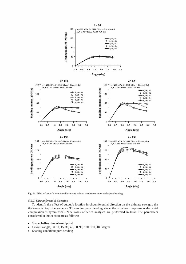
Fig. 16. Effect of cutout’s location with varying column slenderness ratios under pure bending.
5.2.2. Circumferential direction
To identify the effect of cutout’s location in circumferential direction on the ultimate strength, the
thickness is kept the same as 30 mm for pure bending since the structural response under axial
compression is symmetrical. Nine cases of series analyses are performed in total. The parameters
considered in this section are as follows:
Shape: half-rectangular-elliptical
Cutout’s angle, : 0, 15, 30, 45, 60, 90, 120, 150, 180 degree
Loading condition: pure bending
0.0 0.5 1.0 1.5 2.0 2.5 3.0 3.5
0
40
80
120
160
Angle (deg)
σY= 299 MPa, E= 205.8 GPa, ν= 0.3, wo/t= 0.3
Hs x D x t = 12655 x 2700 x 30 mm
λ= 90
Ben
din
g m
om
ent
(MN
m)
ho/Hs= 0.1
ho/Hs= 0.2
ho/Hs= 0.3
ho/Hs= 0.4
ho/Hs= 0.5
0.0 0.5 1.0 1.5 2.0 2.5 3.0 3.5
0
40
80
120
160
Angle (deg)
σY= 299 MPa, E= 205.8 GPa, ν= 0.3, wo/t= 0.3
Hs x D x t = 12655 x 3300 x 30 mm
λ= 110
Ben
din
g m
om
ent
(MN
m)
ho/Hs= 0.1
ho/Hs= 0.2
ho/Hs= 0.3
ho/Hs= 0.4
ho/Hs= 0.5
0.0 0.5 1.0 1.5 2.0 2.5 3.0 3.5
0
40
80
120
160
Angle (deg)
σY= 299 MPa, E= 205.8 GPa, ν= 0.3, wo/t= 0.3
Hs x D x t = 12655 x 3750 x 30 mm
λ= 125
Ben
din
g m
om
ent
(MN
m)
ho/Hs= 0.1
ho/Hs= 0.2
ho/Hs= 0.3
ho/Hs= 0.4
ho/Hs= 0.5
0.0 0.5 1.0 1.5 2.0 2.5 3.0 3.5
0
40
80
120
160
Angle (deg)
σY= 299 MPa, E= 205.8 GPa, ν= 0.3, wo/t= 0.3
Hs x D x t = 12655 x 3900 x 30 mm
λ= 130
Ben
din
g m
om
ent
(MN
m)
ho/Hs= 0.1
ho/Hs= 0.2
ho/Hs= 0.3
ho/Hs= 0.4
ho/Hs= 0.5
0.0 0.5 1.0 1.5 2.0 2.5 3.0 3.5
0
40
80
120
160
Angle (deg)
σY= 299 MPa, E= 205.8 GPa, ν= 0.3, wo/t= 0.3
Hs x D x t = 12655 x 4500 x 30 mm
λ= 150
Ben
din
g m
om
ent
(MN
m)
ho/Hs= 0.1
ho/Hs= 0.2
ho/Hs= 0.3
ho/Hs= 0.4
ho/Hs= 0.5

Fig. 17. Summary of non-dimensionalized load carrying capacity with varying cutout’s location in vertical direction: (a) axial
compression; (b) pure bending.
Figure 18. An example of applied geometries varying cutout’s angle in circumferential direction: (a) 0 degree; (b) 30
degree; (c) 60 degree; (d) 90 degree; (e) 180 degree.
Fig. 19. Effect of cutout’s angle under pure bending: (a) moment-rotation histories; (b) non-dimensionalized load carrying
strength.
(a) (b)
0.0 0.1 0.2 0.3 0.4 0.5 0.6
0.0
0.2
0.4
0.6
0.8
1.0
λ= 90
λ= 110
λ= 125
λ= 130
λ= 150
ho /Hs
Mu
/MP
0.0 0.1 0.2 0.3 0.4 0.5 0.6
0.0
0.2
0.4
0.6
0.8
1.0
λ= 90
λ= 110
λ= 125
λ= 130
λ= 150
ho /Hs
Fu
/FR
(a) (c)(b) (d) (e)
(a) (b)
0 40 80 120 160 200
0.0
0.2
0.4
0.6
0.8
1.0
θ (deg)
Mu
/MP
σY= 299 MPa, E= 205.8 GPa, ν= 0.3, wo/t= 0.3
Hs x h x b x t = 12655 x 1900 x 700 x 30 mm
Half-Rectangular-Elliptical
0.0 1.0 2.0 3.0 4.0 5.0 6.0
0
40
80
120
160
Angle (deg)
Ben
din
g m
om
ent
(MN
m)
σY= 299 MPa, E= 205.8 GPa, ν= 0.3, wo/t= 0.3
Hs x h x b x t = 12655 x 1900 x 700 x 30 mm
Half-Rectangular-Elliptical
θ = 0 deg
θ = 30 deg
θ = 60 deg
θ = 90 deg
θ = 120 deg
θ = 150 deg
θ = 15 deg
θ = 180 deg
θ = 45 deg

Fig. 18 illustrates an example of applied geometries varying cutout’s angle in circumferential
direction, 0~180 degree. Fig. 19 represents moment-rotation histories varying cutout’s angle and
the non-dimensionalized load carrying strength. It is confirmed that when the cutout locates on
compression side ( 0 degree), the ultimate strength shows the minimum strength and as the cutout’s
angle increases, so does the ultimate strength. It is observed that the ultimate strength increases almost
linearly until 90 degree whereas it appears almost constant over 90 degrees ( 120, 150, 180
degree).
5.2.3. Combined effects of aspect ratio, column slenderness ratio and column aspect ratio
To examine the effects of aspect ratio, column slenderness ratio and column aspect ratio on the
ultimate strength, the dimensions of the cutout varies from the boundaries of statistical distribution,
1800 ≤ h ≤ 2900, 600 ≤ b ≤ 1100, as illustrated in Section 3.2. For the selection of parameters,
DOE by using CCD method is applied. Four cases of the maximum diameter varying from 2750 mm to
4250 mm are taken into account with the locations of the cutout in vertical- and
circumferential-direction, /o Sh H = 0.1 and = 0 degree. Thousand eighty cases of series analyses
are performed in total. The parameters considered in this section are as follows:
Shape: rectangular, elliptical, half-rectangular-elliptical
Height of the cutout, h : 1800~2900 mm
Width of the cutout, b : 600~1100 mm
Column slenderness ratio, max /D t : 90, 110, 125, 130, 150
Diameter, maxD : 2750, 3250, 3750, 4250 mm
Loading condition: axial compression and pure bending
Fig. 20. An example of effect of column slenderness ratio for maxD 3750 mm under axial compression.
Fu
/ F
R
0.0 40.0 80.0 120.0 160.0
0.0
0.2
0.4
0.6
0.8
1.0
Reduced Volume (mm3)
Rectangular
Fu
/ F
R
0.0 40.0 80.0 120.0 160.0
0.0
0.2
0.4
0.6
0.8
1.0
Reduced Volume (mm3)
Elliptical
Fu
/ F
R
0.0 40.0 80.0 120.0 160.0
0.0
0.2
0.4
0.6
0.8
1.0
Reduced Volume (mm3)
Half-Rectangular-Elliptical
h= 1800 mm, b= 600 mm
h= 1800 mm, b= 850 mm
h= 1800 mm, b= 1100 mm
h= 2350 mm, b= 600 mm
h= 2350 mm, b= 850 mm
h= 2350 mm, b= 1100 mm
h= 2900 mm, b= 600 mm
h= 2900 mm, b= 850 mm
h= 2900 mm, b= 1100 mm

Fig. 21. An example of effect of column slenderness ratio for maxD 3750 mm under pure bending.
Table A2 in Appendix summarizes the selected design points by using CCD. Figs. 20 and 21 show
an example of the effect of column slenderness ratio on the non-dimensionalized ultimate strength (
maxD = 3750 mm) for three shapes under axial compression and pure bending. It has been observed that
as the reduced volume increases, it lowers the strength and the reduced strength appears nearly the
same regardless of the shape. Figs. 22 and 23 illustrate the non-dimensionalized ultimate strength of
selected design points for 3-shape of cutouts under axial compression and pure bending. It is found that
the ultimate strength reduction appears within the range from 50% to 80% of reference strength for
both loading conditions.
6. Empirical Formulation of the Ultimate Strength
The results of the parametric analysis described in Section 5.3 are used to derive empirical
formulations of predicting the ultimate strength of the circular cylindrical shell with the cutout. Linear
regression equations with least square method are used, as follows:
max/u R D t h b CF F D t h b (3)
max/u P D t h b CM M D t h b (4)
In the above, /u RF F and /u PM M are the non-dimensionalised ultimate strength of axial
compression and pure bending, respectively.
The coefficients of the design formula for axial compression and pure bending are indicated in
Table 3. Regression statistics including the correlation coefficients and the adjusted R-square are
illustrated in Table 4. A correlation between numerical results and the empirical estimations on the
Mu
/
MP
0.0 40.0 80.0 120.0 160.0
0.0
0.2
0.4
0.6
0.8
1.0
Reduced Volume (mm3)
RectangularM
u /
MP
0.0 40.0 80.0 120.0 160.0
0.0
0.2
0.4
0.6
0.8
1.0
Reduced Volume (mm3)
Elliptical
Mu
/
MP
0.0 40.0 80.0 120.0 160.0
0.0
0.2
0.4
0.6
0.8
1.0
Reduced Volume (mm3)
Half-Rectangular-Elliptical
h= 1800 mm, b= 600 mm
h= 1800 mm, b= 850 mm
h= 1800 mm, b= 1100 mm
h= 2350 mm, b= 600 mm
h= 2350 mm, b= 850 mm
h= 2350 mm, b= 1100 mm
h= 2900 mm, b= 600 mm
h= 2900 mm, b= 850 mm
h= 2900 mm, b= 1100 mm

ultimate strength of circular cylindrical shells with the cutout is illustrated in Fig. 24. It is found that
the estimations by the proposed empirical equations well agree to the numerical calculations. This
implies that the proposed empirical equations can be an effective measure of estimating the reduced
ultimate strength of circular cylindrical shells with the cutout.
While the design formulae developed in the present study cover an extensive range of possible
geometrical variations in circular cylindrical shells with the cutout and they must be a good guidance
for wind turbine tower design. It should be cautioned that they may need to be validated further by
comparison with more specific computations and experiments when one may aim at using them for
some special cases of geometric and boundary conditions.
Fig. 22. Summary of the non-dimensionalized ultimate strength under axial compression.
Table 3. Coefficients of design formula
Shape Axial Compression
D (10-6) t (10-3) h (10-6) b (10-3) C
Rectangular 0.486 2.206 -0.248 -0.245 0.698
Elliptical 0.505 1.407 -0.214 -0.229 0.723
Half-Rectangular-Elliptical 0.512 1.700 -0.239 -0.235 0.713
Shape Pure Bending
D (10-6) t (10-3) h (10-6) b (10-3) C
Rectangular -0.141 4.250 -0.151 -0.187 0.791
Elliptical -0.144 3.661 -0.175 -0.172 0.827
Half-Rectangular-Elliptical -0.148 3.984 -0.175 -0.176 0.818
Fu
/ F
R
0.0 40.0 80.0 120.0 160.0
0.0
0.2
0.4
0.6
0.8
1.0
Reduced Volume (mm3)
h= 1800 mm, b= 600 mm
h= 1800 mm, b= 850 mm
h= 1800 mm, b= 1100 mm
Rectangular
Fu
/ F
R
0.0 40.0 80.0 120.0 160.0
0.0
0.2
0.4
0.6
0.8
1.0
Reduced Volume (mm3)
Rectangular
h= 2350 mm, b= 600 mm
h= 2350 mm, b= 850 mm
h= 2350 mm, b= 1100 mm
Fu
/ F
R
0.0 40.0 80.0 120.0 160.0
0.0
0.2
0.4
0.6
0.8
1.0
Reduced Volume (mm3)
Rectangular
h= 2900 mm, b= 600 mm
h= 2900 mm, b= 850 mm
h= 2900 mm, b= 1100 mm
Fu
/ F
R
0.0 40.0 80.0 120.0 160.0
0.0
0.2
0.4
0.6
0.8
1.0
Reduced Volume (mm3)
h= 1800 mm, b= 600 mm
h= 1800 mm, b= 850 mm
h= 1800 mm, b= 1100 mm
Elliptical
Fu
/ F
R
0.0 40.0 80.0 120.0 160.0
0.0
0.2
0.4
0.6
0.8
1.0
Reduced Volume (mm3)
Elliptical
h= 2350 mm, b= 600 mm
h= 2350 mm, b= 850 mm
h= 2350 mm, b= 1100 mm
Fu
/ F
R
0.0 40.0 80.0 120.0 160.0
0.0
0.2
0.4
0.6
0.8
1.0
Reduced Volume (mm3)
Elliptical
h= 2900 mm, b= 600 mm
h= 2900 mm, b= 850 mm
h= 2900 mm, b= 1100 mm
Fu
/ F
R
0.0 40.0 80.0 120.0 160.0
0.0
0.2
0.4
0.6
0.8
1.0
Reduced Volume (mm3)
Half-Rectangular-Elliptical
h= 1800 mm, b= 600 mm
h= 1800 mm, b= 850 mm
h= 1800 mm, b= 1100 mm
Fu
/ F
R
0.0 40.0 80.0 120.0 160.0
0.0
0.2
0.4
0.6
0.8
1.0
Reduced Volume (mm3)
Half-Rectangular-Elliptical
h= 2350 mm, b= 600 mm
h= 2350 mm, b= 850 mm
h= 2350 mm, b= 1100 mm
Fu
/ F
R
0.0 40.0 80.0 120.0 160.0
0.0
0.2
0.4
0.6
0.8
1.0
Reduced Volume (mm3)
Half-Rectangular-Elliptical
h= 2900 mm, b= 600 mm
h= 2900 mm, b= 850 mm
h= 2900 mm, b= 1100 mm

Fig. 23. Summary of the non-dimensionalized ultimate strength under pure bending
7. Conclusion
The aims of this study are to develop numerical modelling technique accurately predicting structural
response taking into account nonlinearities and to numerically examine the effects of various variables
on the ultimate-strength characteristics of wind turbine towers with the cutout. A series of nonlinear
finite element computations are undertaken to achieve these objectives. Several conclusions can be
drawn from the results, as outlined below.
First, the wind turbine structures in service are investigated. The actual dimensional characteristics
of these wind turbine structures and cutouts are identified from the data collected and analyzed.
The nonlinear finite element modelling technique is developed based the mesh convergence study
and validation studies for wind turbine towers with the cutout.
It is confirmed that the effect of cutout’s shape is negligible and the cutout’s location on
compression side shows the minimum ultimate strength. Further, under pure bending, the ultimate
strength appears in uniform when the cutout angle is over 90 degree.
Table 4. Regression statistics
Shape
Axial Compression Pure Bending
2R 2R
Rectangular 0.989 0.977 0.975 0.950
Elliptical 0.989 0.977 0.972 0.943
Half-Rectangular-Elliptical 0.989 0.978 0.978 0.956
Mu
/
MP
0.0 40.0 80.0 120.0 160.0
0.0
0.2
0.4
0.6
0.8
1.0
Reduced Volume (mm3)
Rectangular
h= 1800 mm, b= 600 mm
h= 1800 mm, b= 850 mm
h= 1800 mm, b= 1100 mm
Mu
/
MP
0.0 40.0 80.0 120.0 160.0
0.0
0.2
0.4
0.6
0.8
1.0
Reduced Volume (mm3)
Rectangular
h= 2350 mm, b= 600 mm
h= 2350 mm, b= 850 mm
h= 2350 mm, b= 1100 mm
Mu
/
MP
0.0 40.0 80.0 120.0 160.0
0.0
0.2
0.4
0.6
0.8
1.0
Reduced Volume (mm3)
Rectangular
h= 2900 mm, b= 600 mm
h= 2900 mm, b= 850 mm
h= 2900 mm, b= 1100 mm
Mu
/
MP
0.0 40.0 80.0 120.0 160.0
0.0
0.2
0.4
0.6
0.8
1.0
Reduced Volume (mm3)
h= 1800 mm, b= 600 mm
h= 1800 mm, b= 850 mm
h= 1800 mm, b= 1100 mm
Elliptical
Mu
/
MP
0.0 40.0 80.0 120.0 160.0
0.0
0.2
0.4
0.6
0.8
1.0
Reduced Volume (mm3)
Elliptical
h= 2350 mm, b= 600 mm
h= 2350 mm, b= 850 mm
h= 2350 mm, b= 1100 mm
Mu
/
MP
0.0 40.0 80.0 120.0 160.0
0.0
0.2
0.4
0.6
0.8
1.0
Reduced Volume (mm3)
Elliptical
h= 2900 mm, b= 600 mm
h= 2900 mm, b= 850 mm
h= 2900 mm, b= 1100 mm
Mu
/
MP
0.0 40.0 80.0 120.0 160.0
0.0
0.2
0.4
0.6
0.8
1.0
Reduced Volume (mm3)
h= 1800 mm, b= 600 mm
h= 1800 mm, b= 850 mm
h= 1800 mm, b= 1100 mm
Half-Rectangular-Elliptical
Mu
/
MP
0.0 40.0 80.0 120.0 160.0
0.0
0.2
0.4
0.6
0.8
1.0
Reduced Volume (mm3)
Half-Rectangular-Elliptical
h= 2350 mm, b= 600 mm
h= 2350 mm, b= 850 mm
h= 2350 mm, b= 1100 mm
Mu
/
MP
0.0 40.0 80.0 120.0 160.0
0.0
0.2
0.4
0.6
0.8
1.0
Reduced Volume (mm3)
Half-Rectangular-Elliptical
h= 2900 mm, b= 600 mm
h= 2900 mm, b= 850 mm
h= 2900 mm, b= 1100 mm
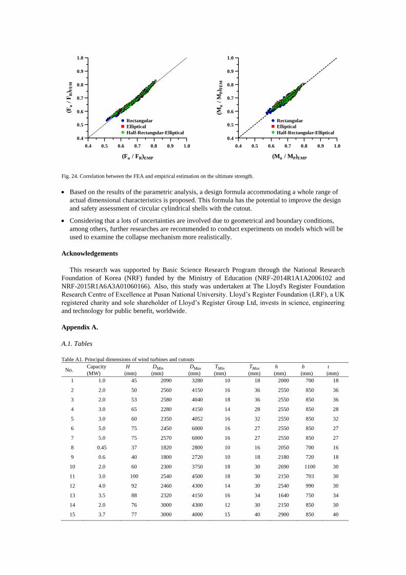
Fig. 24. Correlation between the FEA and empirical estimation on the ultimate strength.
Based on the results of the parametric analysis, a design formula accommodating a whole range of
actual dimensional characteristics is proposed. This formula has the potential to improve the design
and safety assessment of circular cylindrical shells with the cutout.
Considering that a lots of uncertainties are involved due to geometrical and boundary conditions,
among others, further researches are recommended to conduct experiments on models which will be
used to examine the collapse mechanism more realistically.
Acknowledgements
This research was supported by Basic Science Research Program through the National Research
Foundation of Korea (NRF) funded by the Ministry of Education (NRF-2014R1A1A2006102 and
NRF-2015R1A6A3A01060166). Also, this study was undertaken at The Lloyd's Register Foundation
Research Centre of Excellence at Pusan National University. Lloyd’s Register Foundation (LRF), a UK
registered charity and sole shareholder of Lloyd’s Register Group Ltd, invests in science, engineering
and technology for public benefit, worldwide.
Appendix A.
A.1. Tables
Table A1. Principal dimensions of wind turbines and cutouts
No. Capacity
(MW)
H
(mm) MinD
(mm) MaxD
(mm) MinT
(mm) MaxT
(mm)
h
(mm)
b
(mm)
t
(mm)
1 1.0 45 2090 3280 10 18 2000 700 18
2 2.0 50 2560 4150 16 36 2550 850 36
3 2.0 53 2580 4040 18 36 2550 850 36
4 3.0 65 2280 4150 14 28 2550 850 28
5 3.0 60 2350 4052 16 32 2550 850 32
6 5.0 75 2450 6000 16 27 2550 850 27
7 5.0 75 2570 6000 16 27 2550 850 27
8 0.45 37 1820 2800 10 16 2050 700 16
9 0.6 40 1800 2720 10 18 2180 720 18
10 2.0 60 2300 3750 18 30 2690 1100 30
11 3.0 100 2540 4500 18 30 2150 703 30
12 4.0 92 2460 4300 14 30 2540 990 30
13 3.5 88 2320 4150 16 34 1640 750 34
14 2.0 76 3000 4300 12 30 2150 850 30
15 3.7 77 3000 4000 15 40 2900 850 40
0.4 0.5 0.6 0.7 0.8 0.9 1.0
0.4
0.5
0.6
0.7
0.8
0.9
1.0
(Fu
/
FR
) FE
M
(Fu / FR)EMP
Rectangular
Elliptical
Half-Rectangular-Elliptical
0.4 0.5 0.6 0.7 0.8 0.9 1.0
0.4
0.5
0.6
0.7
0.8
0.9
1.0
(Mu
/
MP) F
EM
(Mu / MP)EMP
Rectangular
Elliptical
Half-Rectangular-Elliptical

No. Capacity
(MW)
H
(mm) MinD
(mm) MaxD
(mm) MinT
(mm) MaxT
(mm)
h
(mm)
b
(mm)
t
(mm)
16 2.0 50 2850 4150 20 40 2900 850 40
17 3.0 65 2294 3650 14 28 1997 750 28
18 3.2 60 2150 3720 16 32 2080 800 32
19 2.0 48 2000 3570 18 34 1850 680 34
20 4.2 88 2380 4420 14 34 2200 850 34
21 2.6 70 2210 2980 16 28 1920 700 28
22 2.2 65 2370 3020 16 28 1900 680 28
23 2.7 69 2450 2950 14 30 2100 680 30
24 3.4 70 2340 3800 16 30 2020 750 30
25 4.2 80 2240 3650 14 32 1980 680 32
26 2.0 55 2200 3400 14 28 1900 720 28
27 2.9 85 2320 3860 14 30 2080 780 30
28 2.9 75 2460 3680 14 28 2280 820 28
29 1.8 50 1780 2900 16 28 1870 690 28
30 3.7 78 2240 3780 14 32 1990 750 32
31 3.0 70 2370 3720 14 28 1930 680 28
32 1.8 55 1890 2890 16 28 1880 680 28
33 2.2 60 1920 3220 14 30 2050 720 30
34 3.4 78 2360 3680 14 30 1990 680 30
35 3.2 65 2280 3540 16 28 1920 800 28
36 2.6 55 2360 3640 14 26 1900 680 26
37 1.8 50 1760 2700 14 28 1840 680 28
38 1.7 55 1680 2740 12 26 1900 650 26
39 3.5 68 2320 3640 14 30 1960 700 30
40 2.7 65 2240 3580 14 32 1990 780 32
41 3.4 84 2450 3840 16 28 2000 800 28
42 3.0 65 2280 3480 16 30 1980 720 30
43 1.6 50 1780 2690 14 28 1780 780 28
44 2.6 60 1880 3640 16 30 1990 680 30
45 3.0 70 2264 3700 12 32 2040 720 32
46 3.6 68 2380 3680 14 32 1980 640 32
47 2.3 50 2210 3200 12 28 1880 684 28
48 1.8 50 1760 2700 14 28 1840 680 28
49 1.6 55 1720 2860 12 28 1880 650 28
50 3.6 73 2260 3680 14 32 1994 686 32
51 2.4 55 2200 3400 14 28 1800 640 28
52 4.1 78 2260 4100 14 32 2100 780 32
53 1.8 52 2140 3360 12 22 1980 720 22
54 2.6 65 2420 3860 16 32 2860 780 32
55 2.4 60 2380 3900 16 34 2200 650 34
56 2.0 55 1980 3450 12 30 2640 700 30
57 3.4 65 2340 3640 14 34 1980 660 34
58 1.9 50 1840 2640 14 26 2000 700 26
59 5.0 88 2570 4230 16 32 2240 650 32
60 0.8 40 1750 2900 10 28 1990 650 28
61 4.0 80 1900 2890 14 28 2000 720 28
62 2.0 64 2320 3840 14 30 2720 980 30
63 3.2 80 2640 3840 14 32 2080 680 32
No. Capacity
(MW)
H
(mm) MinD
(mm) MaxD
(mm) MinT
(mm) MaxT
(mm)
h
(mm)
b
(mm)
t
(mm)
64 4.0 75 2360 4180 14 28 2120 640 28
65 3.1 65 2240 3680 16 32 1970 680 32
66 4.0 80 2320 3860 12 28 1990 690 28
67 3.4 83 2360 3940 12 32 2220 710 32
68 2.4 60 2240 2940 10 28 1940 650 28
69 1.8 50 1780 2680 12 24 1890 640 24
70 2.1 74 2400 3620 10 32 2100 680 32
71 3.4 78 2180 3680 12 34 2200 740 34
72 2.2 52 1860 2870 10 28 2050 650 28
73 2.8 68 2150 3720 12 32 1940 680 32
74 3.4 68 2240 3640 14 28 2000 660 28
75 2.2 55 1990 2870 16 30 1980 720 30
76 3.9 84 2280 3640 14 28 2120 750 28
77 2.6 80 2180 3640 12 30 1990 680 30
78 2.4 60 2120 3360 12 32 1970 710 32
79 2.6 67 2240 3420 12 26 1990 672 26
80 3.1 80 2180 3640 14 32 1940 690 32
81 3.0 72 2140 3480 12 32 2130 700 32
82 2.1 65 1960 3580 12 32 1980 640 32
83 3.3 80 2240 4000 12 32 2200 840 32
84 2.4 64 2260 3800 14 32 2120 680 32
85 1.7 52 1790 3140 12 32 1980 720 32
86 3.7 78 2240 3780 14 32 1990 750 32
87 2.8 72 2260 3450 12 30 2050 750 30
88 1.9 55 1680 3120 12 30 1960 724 30
89 2.4 68 1890 3480 13 28 2150 750 28
90 3.7 87 2480 3780 12 32 2040 750 32
91 3.4 80 2340 3750 14 32 2000 810 32
92 2.7 68 2180 3580 12 30 2000 780 30
93 2.1 64 1860 2940 10 28 1960 680 28
94 2.0 60 1600 2900 16 30 1880 750 30
95 3.2 66 2200 3690 10 28 1890 690 28
96 2.4 60 2140 3640 10 30 1800 640 30
97 3.0 80 2200 3450 12 30 1920 740 30
98 2.4 72 2180 3590 14 32 2100 720 32
99 1.4 45 1640 2610 10 26 1680 620 26
100 3.1 65 1960 3580 12 28 1890 690 28
101 2.7 65 2230 3690 14 28 2200 740 28
102 3.4 73 2240 3640 12 27 2050 700 27

Table A2. An example of selected design points by DOE with CCD method
No. /D t h (mm) b (mm) No. /D t h (mm) b (mm)
DP1 90
1800 600
DP26 90
2900 1100
DP2 110 DP27 110
DP3 125 DP28 125
DP4 130 DP29 130
DP5 150 DP30 150
DP6 90
1800 850
DP31 90
2900 600
DP7 110 DP32 110
DP8 125 DP33 125
DP9 130 DP34 130
DP10 150 DP35 150
DP11 90
1800 1100
DP36 90
2900 850
DP12 110 DP37 110
DP13 125 DP38 125
DP14 130 DP39 130
DP15 150 DP40 150
DP16 90
2350 600
DP41 90
2900 1100
DP17 110 DP42 110
DP18 125 DP43 125
DP19 130 DP44 130
DP20 150 DP45 150
DP21 90
2350 850 -
DP22 110
DP23 125
DP24 130
DP25 150
References
ANSYS, 2015. User’s manual (version 16.1). ANSYS Inc., Canonsburg, PA, USA.
Azizian ZG and Roberts TM. 1983. Buckling and elasto-plastic collapse of perforated plates.
Proceedings of the International Conference on Instability and Plastic Collapse of Steel Structures,
Granada Publishing, London, UK, pp. 392-398.
Betten J and Shin CH. 2000. Elasto-plastic buckling analysis of rectangular plates subjected to biaxial
loads. Forschung im Ingenieurwesen, 65: 273-278.
Brazier LG. 1927. On the flexure of thin cylindrical shells and other "thin" sections. Proceedings of
Royal Society of London, Series A. 116(773): 104–114.
Brown CJ and Yettram AL. 1986. The elastic stability of square perforated plates under combinations
of bending, shear and direct load. Thin-Walled Structures, 4(3): 239-246.
Collu M, Brennan FP and Patel MH. 2014. Conceptual design of floating support structure for an
offshore vertical axis wind turbine: the lessons learnt. Ships and Offshore Structures, 9(1): 3-21.
Dimopoulos CA and Gantes CJ. 2012. Experimental investigation of buckling of wind turbine tower
cylindrical shells with opening and stiffening under bending. Thin-Walled Structures, 54: 140-155.
DIN 18800-4. 1990. Stahlbauten: Stabilitätsfälle, Schalenbeulen, Beuth Verlag, Berlin, Germany.
DNVGL. 2013a. Design of offshore wind turbine structures. Report No.: DNV-OS-J101, Det Norske
Veritas, Oslo, Norway.
DNVGL. 2013b. Buckling strength of shells. DNV-RP-C202, Det Norske Veritas, Oslo, Norway.

Durban D and Zuckerman Z. 1999. Elasto-plastic buckling of rectangular plates in biaxial
compression/tension. Int. Journal of Mechanical Science, 41: 751-765.
ECCS. 1980. Technical Committee 8, Structural Stability, TWG 8.4-Shells, Buckling of Steel Shells.
European Design Recommendations, 1st edition.
El-Sawy KM, Nazmy AS and Martini MI. 2004. Elasto-plastic buckling of perforated plates under
uniaxial compression. Thin-Walled Structures, 42: 1083-1101.
EN1993-1.6. 2006. European Committee for Standardization, Eurocode 3: Design of Steel Structures,
Part 1–6: Strength and Stability of Shell Structures.
EWEA. 2014. Wind in power, 2014 European statistics, European Wind Energy Association, Brussels,
Belgium, Available online: http://www.ewea.org/fileadmin/files/library/publications/statistics
/EWEA- Annual-Statistics-2014.pdf.
Fabian O. 1977. Collapse of cylindrical, elastic tubes under combined bending, pressure and axial
loads. Int. Journal of Solids Structures, 13: 1257-1270.
Gellin S. 1980. The plastic buckling of long cylindrical shell under pure bending. Int. Journal of Solids
Structures, 16: 397-407.
Ghazijahani TG, Jiao H and Holloway D. 2015. Structural behaviour of shells with different cutouts
under compression: An experimental study. Journal of Construction Steel Research, 105: 129-137.
Guo L, Yang S and Jiao H. 2013. Behaviour of thin-walled circular hollow section tubes subjected to
bending. Thin-Walled Structures, 73: 281-289.
Han H, Cheng J, Taheri F and Pegg N. 2006. Numerical and experimental investigations of the
response of aluminum cylinders with a cutout subject to axial compression. Thin-Walled Structure,
44: 254-270.
Jensen FM, Falzon BG, Ankersen J and Stang H. 2006. Structural testing and numerical simulation of
34m composite wind turbine blade. Composite Structures, 76: 52-61.
Ju GT and Kyriakides S. 1992. Bifurcation and localization instabilities in cylindrical shells under
bending II. Predictions. Int. Journal of Solids Structures, 29: 1143-1171.
Jullien J and Limam A. 1998. Effects of openings of the buckling of cylindrical shells subjected to
axial compression. Thin-Walled Structure, 31: 187-202.
Kim UN, Choe IH and Paik JK. 2009. Buckling and ultimate strength of perforated plate panels subject
to axial compression: experimental and numerical investigations with design formulations. Ships
and Offshore Structures, 4(4): 337-361.
Kyriakides S and Ju GT. 1992. Bifurcation and localization instabilities in cylindrical shells under
bending. I. Experiments. Int. Journal of Solids Structures, 29: 1117-1142.
Kühlmeier L. 2007. Buckling of wind turbine rotor blades. Analysis, design and experimental
validation, PhD thesis, Aalborg University, Denmark, ISBN: 87-91464-00-5.
Lee HG and Park J. 2016. Static test until structural collapse after fatigue testing of a full-scale wind
turbine blade. Composite Structures, 136: 251-257.
Overgaard LCT, Lund E and Camanho PP. 2010a. A methodology for the structural analysis of
composite wind turbine blades under geometric and material induced instabilities. Composite
Structures, 88: 1092-1109.
Overgaard LCT, Lund E and Thomsen OT. 2010b. Structural collapse of a wind turbine blade, Part A:
static test and equivalent single layered models. Composites Part A: Applied Science and
Manufacturing, 41: 257-270.

Overgaard LCT and Lund E. 2010. Structural collapse of a wind turbine blade, Part B: progressive
interlaminar failure models, Composites Part A: Applied Science and Manufacturing, 41: 271-283.
Paik JK. 2007. Ultimate strength of steel plates with a single circular hole under axial compressive
loading along short edges. Ships and Offshore Structures, 2(4): 355-360.
Reissner E. 1961. On finite pure bending of cylindrical tubes. Ö sterreichisches Ingenieur-Archiv, 15:
165-172.
Sabir AB and Chow FY. 1983. Elastic buckling of flat panels containing circular and square holes.
Proceedings of the International Conference on Instability and Plastic Collapse of Steel Structures,
Granada Publishing, London, UK, pp. 311-321.
Schenk CA and Schuёller GI. 2007. Buckling analysis of cylindrical shells with cutouts including
random boundary and geometric imperfections. Cimputer Methods in Applied Mechanics and
Engineering, 196: 3424-3434.
Seide P and Weingarten VI. 1961. On the buckling of circular cylindrical shells under pure bending.
Journal of Applied Mechanics, 28: 112-116.
Shangmugam NE, Thevendran V and Tan YH. 1999. Design formula for axially compressed perforated
plates. Thin-Walled Structures, 34(1): 1-20.
Shariati M and Rokhi MM. 2008. Numerical and experimental investigations on buckling of steel
cylindrical shells with elliptical cutout subject to axial compression. Thin-Walled Structure, 46:
1251-1261.
Shariati M and Rokhi MM. 2010. Buckling of steel cylindrical shells with an elliptical cutout. Int.
Journal of Steel Structures, 10: 193-205.
Sherman DR. 1976. Tests of circular steel tubes in bending. ASCE Journal of the Structural Division,
102: 2181-2195.
Tennyson RC. 1968. The effects of unreinforced circular cutouts on the buckling of circular cylindrical
shells under axial compression. Journal of Engineering for Industry, 90(4): 541-546.
Wang G, Sun H, Peng H and Uemori R. 2009. Buckling and ultimate strength of plates with openings.
Ships and Offshore Structures, 4(1): 43-53.
Yang J, Peng C, Xiao J, Zeng J, Xing S and Jin J. 2013. Structural investigation of composite wind
turbine blade considering structural collapse in full-scale static tests. Composite Structures, 97: 15–
29.
Yeh MK, Lin MC, and Wu WT. 1999. Bending Buckling of an Elasto-plastic Cylindrical Shell with a
Cutout. Engineering Structures, 21: 996-1005.