EEE1012 Introduction to Electrical & Electronics Engineering Chapter 1: Fundamental Laws of...
26
EEE1012 Introduction to Electrical & Electronics Engineering Chapter 1: Fundamental Laws of Electricity by Muhazam Mustapha, July 2010
-
Upload
cecil-dominic-tucker -
Category
Documents
-
view
227 -
download
2
Transcript of EEE1012 Introduction to Electrical & Electronics Engineering Chapter 1: Fundamental Laws of...

EEE1012Introduction to Electrical &
Electronics EngineeringChapter 1: Fundamental Laws of Electricity
by Muhazam Mustapha, July 2010
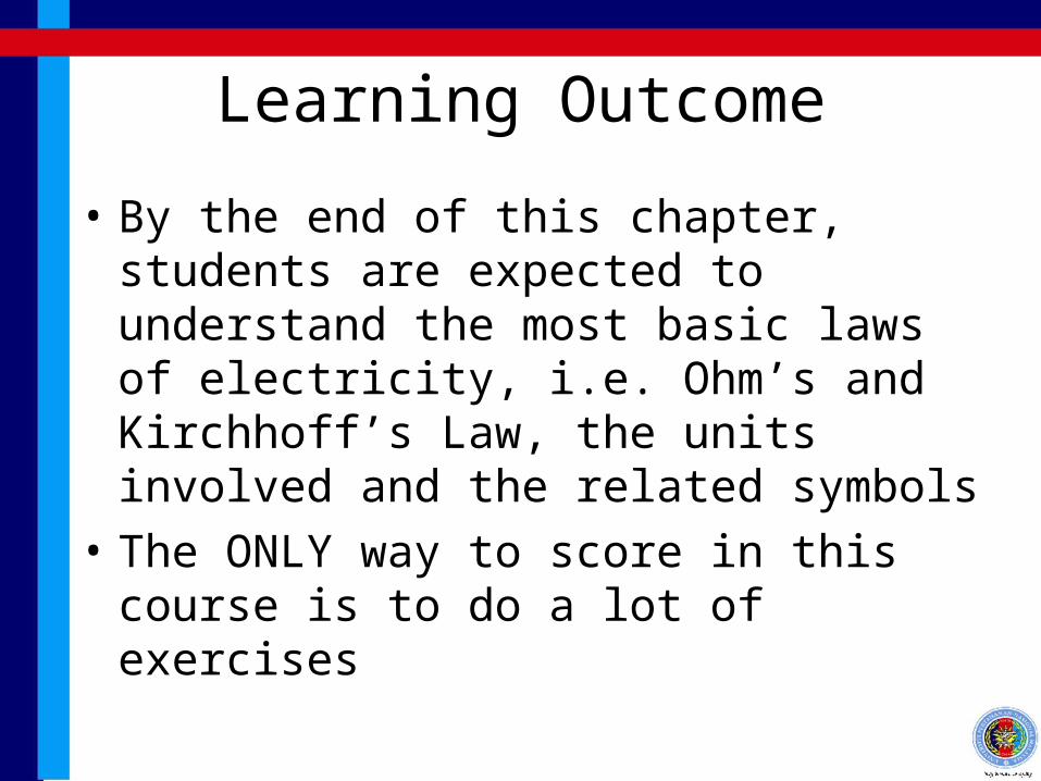
Learning Outcome
• By the end of this chapter, students are expected to understand the most basic laws of electricity, i.e. Ohm’s and Kirchhoff’s Law, the units involved and the related symbols
• The ONLY way to score in this course is to do a lot of exercises
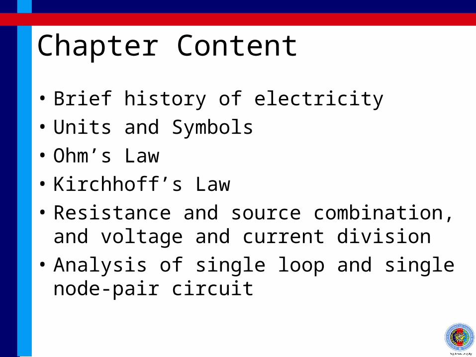
Chapter Content
• Brief history of electricity
• Units and Symbols
• Ohm’s Law
• Kirchhoff’s Law
• Resistance and source combination, and voltage and current division
• Analysis of single loop and single node-pair circuit
Brief History of Electricity
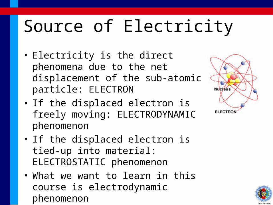
Source of Electricity
• Electricity is the direct phenomena due to the net displacement of the sub-atomic particle: ELECTRON
• If the displaced electron is freely moving: ELECTRODYNAMIC phenomenon
• If the displaced electron is tied-up into material: ELECTROSTATIC phenomenon
• What we want to learn in this course is electrodynamic phenomenon
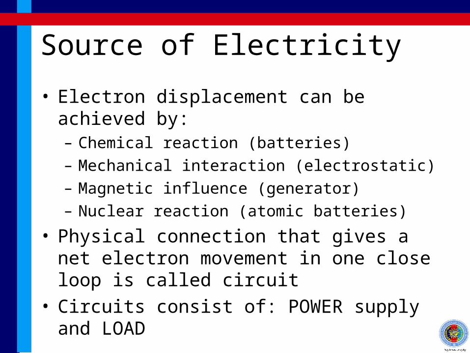
Source of Electricity
• Electron displacement can be achieved by:– Chemical reaction (batteries)– Mechanical interaction (electrostatic)– Magnetic influence (generator)– Nuclear reaction (atomic batteries)
• Physical connection that gives a net electron movement in one close loop is called circuit
• Circuits consist of: POWER supply and LOAD
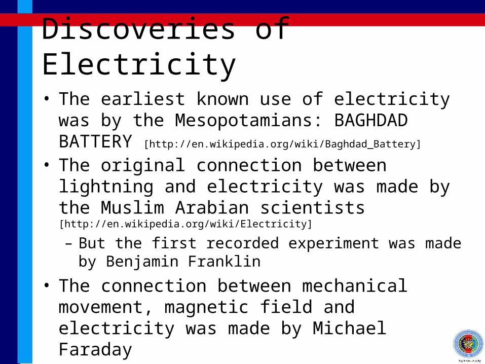
Discoveries of Electricity
• The earliest known use of electricity was by the Mesopotamians: BAGHDAD BATTERY [http://en.wikipedia.org/wiki/Baghdad_Battery]
• The original connection between lightning and electricity was made by the Muslim Arabian scientists [http://en.wikipedia.org/wiki/Electricity]
– But the first recorded experiment was made by Benjamin Franklin
• The connection between mechanical movement, magnetic field and electricity was made by Michael Faraday

Units and Symbols
Electrical Units
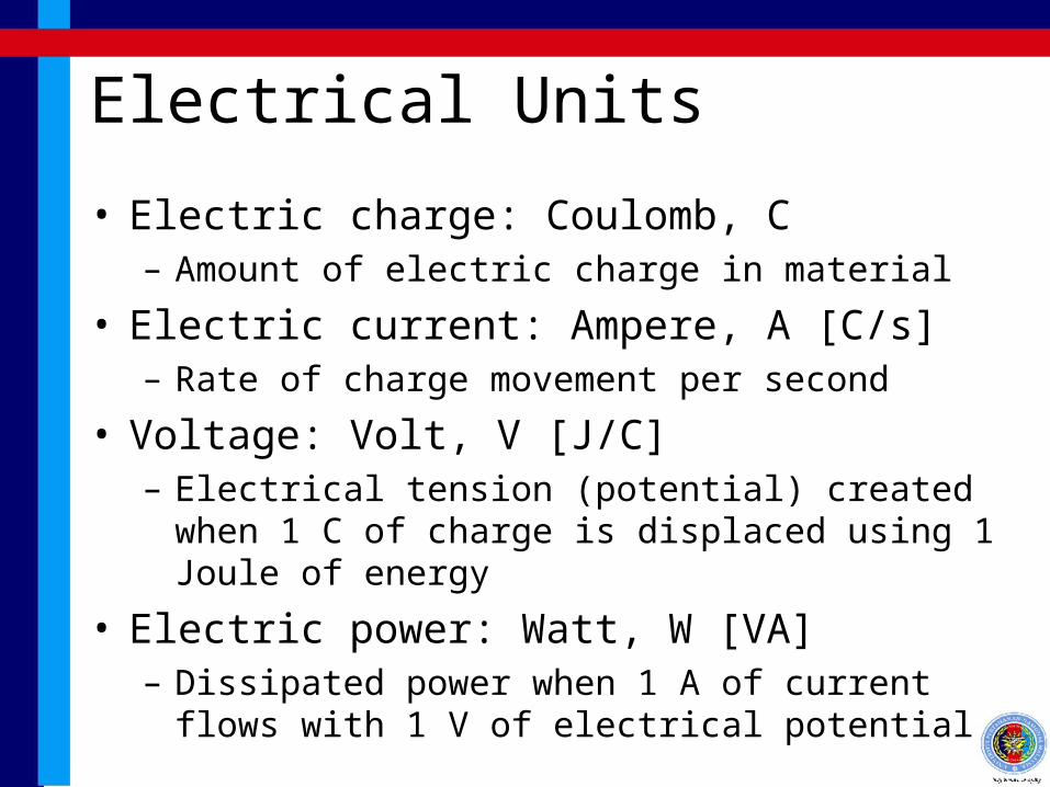
• Electric charge: Coulomb, C– Amount of electric charge in material
• Electric current: Ampere, A [C/s]– Rate of charge movement per second
• Voltage: Volt, V [J/C]– Electrical tension (potential) created when 1 C of
charge is displaced using 1 Joule of energy
• Electric power: Watt, W [VA]– Dissipated power when 1 A of current flows with 1 V
of electrical potential
Electrical Units
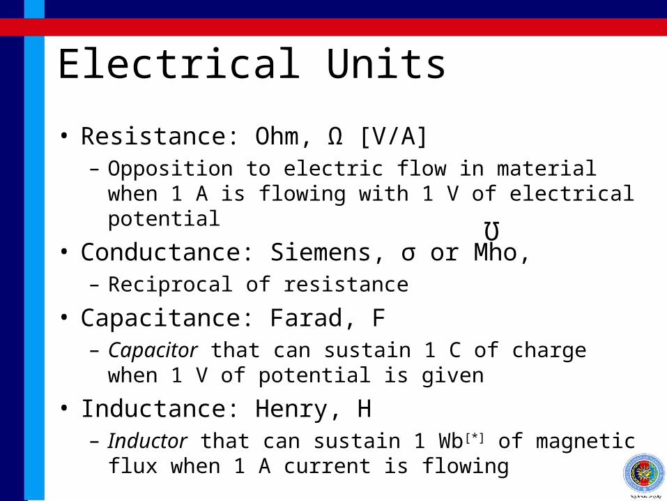
• Resistance: Ohm, Ω [V/A]– Opposition to electric flow in material when 1 A is
flowing with 1 V of electrical potential
• Conductance: Siemens, σ or Mho,– Reciprocal of resistance
• Capacitance: Farad, F– Capacitor that can sustain 1 C of charge when 1 V of
potential is given
• Inductance: Henry, H– Inductor that can sustain 1 Wb[*] of magnetic flux
when 1 A current is flowing
Ω

Circuit Symbols
Capacitor
Load
Current Supply Inductor
Voltage Supply
Resistor

Ohm’s and Kirchhoff’s Law
Ohm’s Law
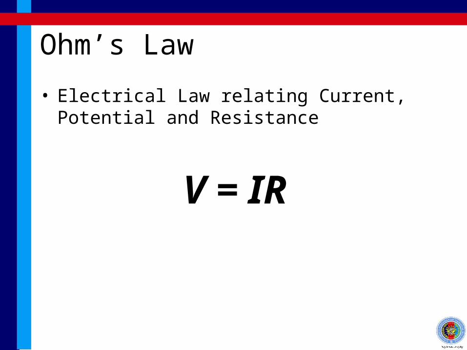
• Electrical Law relating Current, Potential and Resistance
V = IR

Kirchhoff’s Voltage Law
• In closed loop circuit, the total voltage supply is equal to the total voltage drop
V6
V1
V2 V3
V4
V5
V1 + V2 + V3
= V4 + V5 + V6

Kirchhoff’s Current Law
• At a circuit junction (node), the total incoming current is equal to the total out-going current
I3
I1 + I2 + I5
= V3 + V4I4
I2
I1I5

Circuit Simplification

Component in Series
• Components are connected head-to-tail• Series current supplies are not legal
arrangement without considering internal conductance, unless they are the same values
• Voltage supplies are combined by summing up
VT V2
V3
VT = V1 + V2 + V3
V1

Components in Series
• Voltage drops ratio across resistors are equal to the resistance ratio
• Currents are the same through all components• Resistors are combined by summing up
T
3
T
3
T
2
T
2
T
1
T
1
R
R
V
V,
R
R
V
V,
R
R
V
V
V1 V2 V3
I1 I2 I3
R1 R2 R3
VT
RT
321T R R R R 321 I I I
Components in Parallel
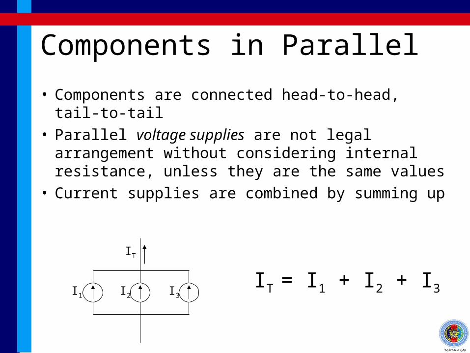
• Components are connected head-to-head, tail-to-tail
• Parallel voltage supplies are not legal arrangement without considering internal resistance, unless they are the same values
• Current supplies are combined by summing up
IT = I1 + I2 + I3
IT
I1 I2 I3

Components in Parallel
• Current ratio through resistors are equal to the conductance ratio
• Voltage are the same across all components• Resistors are combined by combining
conductance
T
3
T
3
T
2
T
2
T
1
T
1
G
G
I
I,
G
G
I
I,
G
G
I
I
V1 V2 V3
I1 I2 I3
R1 R2 R3RT
321T R
1
R
1
R
1
R
1
321 V V V
IT

Bridge Circuit
• Couldn’t be resolved to series or parallel• Analysis can be done as mesh or nodal analysis
(Chapter 2)
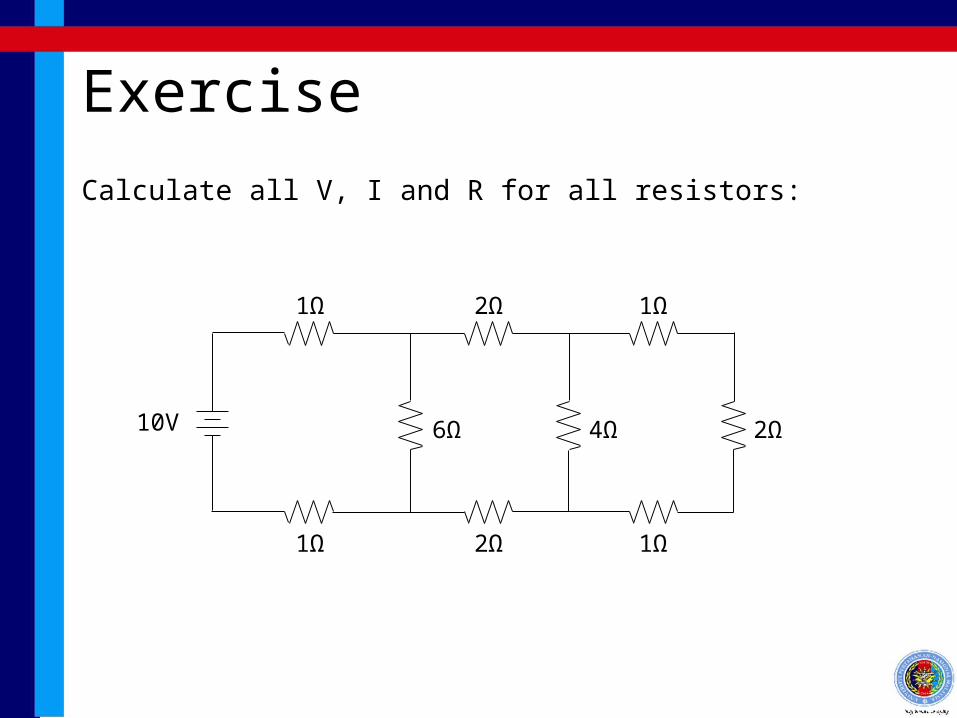
Exercise
Calculate all V, I and R for all resistors:
10V
1Ω
1Ω
6Ω
2Ω
2Ω
1Ω
1Ω
4Ω 2Ω

Some Special Notations

Ground & Power• Power can just be shown as a bubble at the top
– This simplifies the circuit and shows voltage more clearly
• Ground is a COMMON point whose voltage is assumed to be at a reference point 0V
20V
20V
same point
POWER
GROUND (0V)
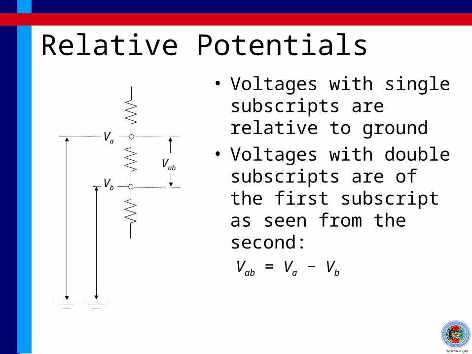
Relative Potentials• Voltages with single
subscripts are relative to ground
• Voltages with double subscripts are of the first subscript as seen from the second:Vab = Va − Vb
Va
Vb
Vab

Parallel Operator
R1R2
R1 + R2
=R1 R2=RT
R1 R2