EEDEN09-204_FXDQ-NBVE_tcm135-112739.pdf
15
Slim Concealed Ceiling Unit FXDQ-NBVE air conditioning systems technical data
-
Upload
vvukmirovic2 -
Category
Documents
-
view
215 -
download
1
Transcript of EEDEN09-204_FXDQ-NBVE_tcm135-112739.pdf
Slim Concealed Ceiling Unit
FXDQ-NBVE
air conditioning systems
technical data
Slim Concealed Ceiling Unit
FXDQ-NBVE
technical dataair conditioning systems
• VRV® Systems • Indoor Units 1
• Indoor Units • SLIM CONCEALED CEILING UNIT • FXDQ-NBVE
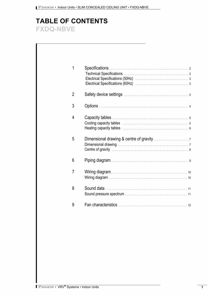
TABLE OF CONTENTSFXDQ-NBVE
1 Specifications . . . . . . . . . . . . . . . . . . . . . . . . . . . . . . . . . . . . . . . . . . . . . . . . . . . . . . . 2 Technical Specifications . . . . . . . . . . . . . . . . . . . . . . . . . . . . . . . . . . . . . . . . . . . . . 2 Electrical Specifications (50Hz) . . . . . . . . . . . . . . . . . . . . . . . . . . . . . . . . . . . . . 3 Electrical Specifications (60Hz) . . . . . . . . . . . . . . . . . . . . . . . . . . . . . . . . . . . . . 3
2 Safety device settings . . . . . . . . . . . . . . . . . . . . . . . . . . . . . . . . . . . . . . . . . . . . . 4
3 Options . . . . . . . . . . . . . . . . . . . . . . . . . . . . . . . . . . . . . . . . . . . . . . . . . . . . . . . . . . . . . . 4
4 Capacity tables . . . . . . . . . . . . . . . . . . . . . . . . . . . . . . . . . . . . . . . . . . . . . . . . . . . . . 5Cooling capacity tables . . . . . . . . . . . . . . . . . . . . . . . . . . . . . . . . . . . . . . . . . . . . . . 5Heating capacity tables . . . . . . . . . . . . . . . . . . . . . . . . . . . . . . . . . . . . . . . . . . . . . . 6
5 Dimensional drawing & centre of gravity . . . . . . . . . . . . . . . . . . . . . . . . 7Dimensional drawing . . . . . . . . . . . . . . . . . . . . . . . . . . . . . . . . . . . . . . . . . . . . . . . . . 7Centre of gravity . . . . . . . . . . . . . . . . . . . . . . . . . . . . . . . . . . . . . . . . . . . . . . . . . . . . . 8
6 Piping diagram. . . . . . . . . . . . . . . . . . . . . . . . . . . . . . . . . . . . . . . . . . . . . . . . . . . . . . 9
7 Wiring diagram. . . . . . . . . . . . . . . . . . . . . . . . . . . . . . . . . . . . . . . . . . . . . . . . . . . . . 10Wiring diagram . . . . . . . . . . . . . . . . . . . . . . . . . . . . . . . . . . . . . . . . . . . . . . . . . . . . . . 10
8 Sound data . . . . . . . . . . . . . . . . . . . . . . . . . . . . . . . . . . . . . . . . . . . . . . . . . . . . . . . . . 11Sound pressure spectrum . . . . . . . . . . . . . . . . . . . . . . . . . . . . . . . . . . . . . . . . . . . 11
9 Fan characteristics . . . . . . . . . . . . . . . . . . . . . . . . . . . . . . . . . . . . . . . . . . . . . . . . 12
• Indoor Units • SLIM CONCEALED CEILING UNIT • FXDQ-NBVE
1
2
1 Specifications
® System oor Unit Q-NBVE m Concea
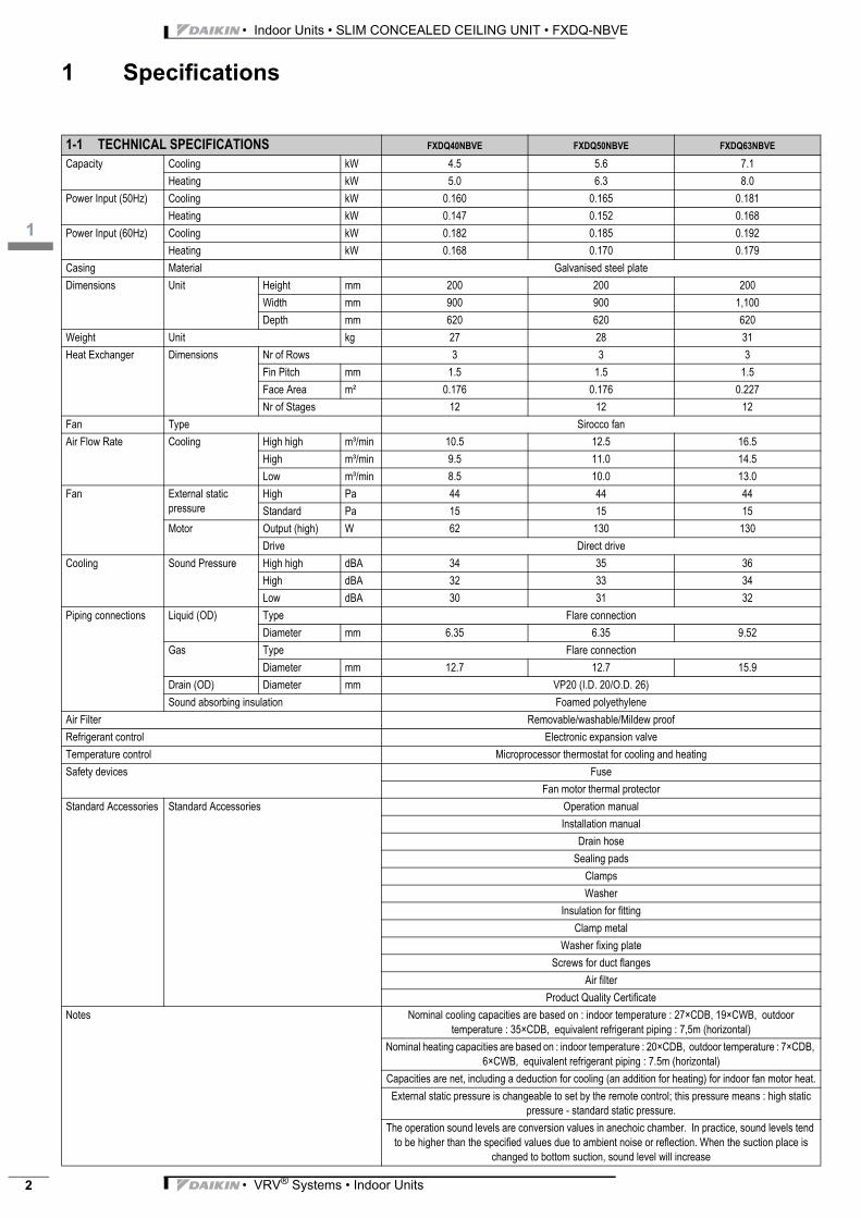
VRV Ind FXD Sli1-1 TECHNICAL SPECIFICATIONS FXDQ40NBVE FXDQ50NBVE FXDQ63NBVECapacity Cooling kW 4.5 5.6 7.1Heating kW 5.0 6.3 8.0
Power Input (50Hz) Cooling kW 0.160 0.165 0.181Heating kW 0.147 0.152 0.168
Power Input (60Hz) Cooling kW 0.182 0.185 0.192Heating kW 0.168 0.170 0.179
Casing Material Galvanised steel plateDimensions Unit Height mm 200 200 200
Width mm 900 900 1,100Depth mm 620 620 620
Weight Unit kg 27 28 31Heat Exchanger Dimensions Nr of Rows 3 3 3
Fin Pitch mm 1.5 1.5 1.5Face Area m² 0.176 0.176 0.227Nr of Stages 12 12 12
Fan Type Sirocco fanAir Flow Rate Cooling High high m³/min 10.5 12.5 16.5
High m³/min 9.5 11.0 14.5Low m³/min 8.5 10.0 13.0
Fan External static pressure
High Pa 44 44 44Standard Pa 15 15 15
Motor Output (high) W 62 130 130Drive Direct drive
Cooling Sound Pressure High high dBA 34 35 36High dBA 32 33 34Low dBA 30 31 32
Piping connections Liquid (OD) Type Flare connectionDiameter mm 6.35 6.35 9.52
Gas Type Flare connectionDiameter mm 12.7 12.7 15.9
Drain (OD) Diameter mm VP20 (I.D. 20/O.D. 26)Sound absorbing insulation Foamed polyethylene
Air Filter Removable/washable/Mildew proofRefrigerant control Electronic expansion valveTemperature control Microprocessor thermostat for cooling and heatingSafety devices Fuse
Fan motor thermal protectorStandard Accessories Standard Accessories Operation manual
Installation manualDrain hose
Sealing padsClampsWasher
Insulation for fittingClamp metal
Washer fixing plateScrews for duct flanges
Air filterProduct Quality Certificate
Notes Nominal cooling capacities are based on : indoor temperature : 27×CDB, 19×CWB, outdoor temperature : 35×CDB, equivalent refrigerant piping : 7,5m (horizontal)
Nominal heating capacities are based on : indoor temperature : 20×CDB, outdoor temperature : 7×CDB, 6×CWB, equivalent refrigerant piping : 7.5m (horizontal)
Capacities are net, including a deduction for cooling (an addition for heating) for indoor fan motor heat.External static pressure is changeable to set by the remote control; this pressure means : high static
pressure - standard static pressure.The operation sound levels are conversion values in anechoic chamber. In practice, sound levels tend
to be higher than the specified values due to ambient noise or reflection. When the suction place is changed to bottom suction, sound level will increase
• VRV® Systems • Indoor Units
3
1
• Indoor Units • SLIM CONCEALED CEILING UNIT • FXDQ-NBVE
1 Specifications
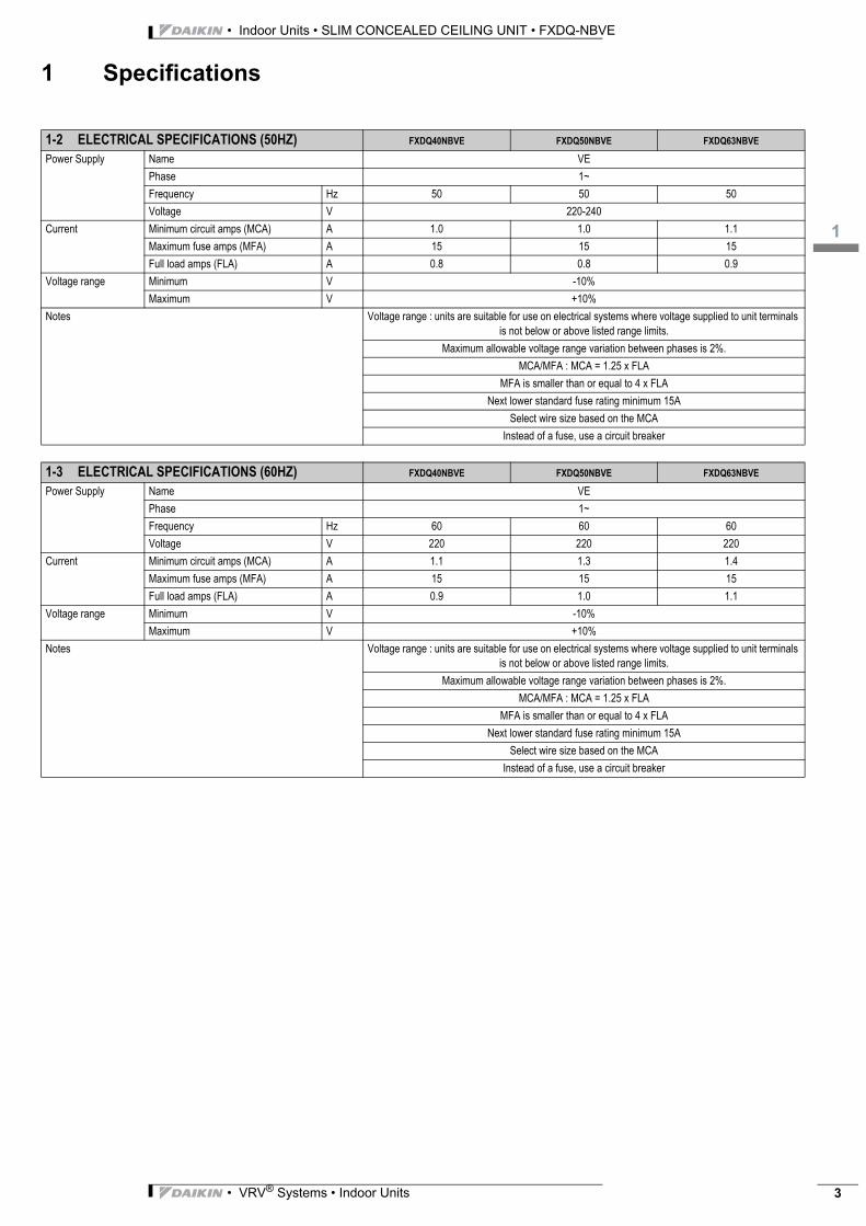
1-2 ELECTRICAL SPECIFICATIONS (50HZ) FXDQ40NBVE FXDQ50NBVE FXDQ63NBVE
Power Supply Name VEPhase 1~Frequency Hz 50 50 50Voltage V 220-240
Current Minimum circuit amps (MCA) A 1.0 1.0 1.1Maximum fuse amps (MFA) A 15 15 15Full load amps (FLA) A 0.8 0.8 0.9
Voltage range Minimum V -10%Maximum V +10%
Notes Voltage range : units are suitable for use on electrical systems where voltage supplied to unit terminals is not below or above listed range limits.
Maximum allowable voltage range variation between phases is 2%.MCA/MFA : MCA = 1.25 x FLA
MFA is smaller than or equal to 4 x FLANext lower standard fuse rating minimum 15A
Select wire size based on the MCAInstead of a fuse, use a circuit breaker
1-3 ELECTRICAL SPECIFICATIONS (60HZ) FXDQ40NBVE FXDQ50NBVE FXDQ63NBVE
Power Supply Name VEPhase 1~Frequency Hz 60 60 60Voltage V 220 220 220
Current Minimum circuit amps (MCA) A 1.1 1.3 1.4Maximum fuse amps (MFA) A 15 15 15Full load amps (FLA) A 0.9 1.0 1.1
Voltage range Minimum V -10%Maximum V +10%
Notes Voltage range : units are suitable for use on electrical systems where voltage supplied to unit terminals is not below or above listed range limits.
Maximum allowable voltage range variation between phases is 2%.MCA/MFA : MCA = 1.25 x FLA
MFA is smaller than or equal to 4 x FLANext lower standard fuse rating minimum 15A
Select wire size based on the MCAInstead of a fuse, use a circuit breaker
• VRV® Systems • Indoor Units 3
• Indoor Units • SLIM CONCEALED CEILING UNIT • FXDQ-NBVE
2
4
2 Safety device settings
3 Options
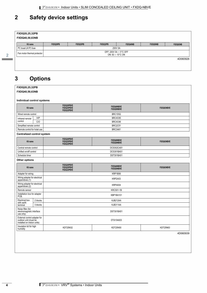
FXDQ20,25,32PB
FXDQ40,50,63NB
4D060926
Kit name FXDQ20PB FXDQ25PB FXDQ32PB
PC boad (A1P) fuse 250V 5A
Fan motor thermal protectorOFF: 250V 5A � 5°C OFF
ON: 83 � 15°C ON
FXDQ40NB FXDQ50NB FXDQ63NB
FXDQ20,25,32PB
FXDQ40,50,63NB
Individual control systems
Centralized control system
Other options
4D060939
Kit name
FXDQ20PBVE
FXDQ25PBVE
FXDQ32PBVE
FXDQ40NBVE
FXDQ50NBVEFXDQ63NBVE
Wired remote control BRC1D52
Infrared remote control
H/P BRC4C65
C/O BRC4C66
Simplified remote control BRC2C51
Remote control for hotel use BRC3A61
Kit name
FXDQ20PBVE
FXDQ25PBVE
FXDQ32PBVE
FXDQ40NBVE
FXDQ50NBVEFXDQ63NBVE
Central remote control DCS302CA51
Unified on/off control DCS301BA51
Schedule timer DST301BA51
Kit name
FXDQ20PBVE
FXDQ25PBVE
FXDQ32PBVE
FXDQ40NBVE
FXDQ50NBVEFXDQ63NBVE
Adapter for wiring KRP1B56
Wiring adapter for electrical appendices (1)
KRP2A53
Wiring adapter for electrical appendices (2)
KRP4A54
Remote sensor KRCS01-1B
Installation box for adapter PCB.
KBP1BA101
Electrical box with earth terminal
2 blocks KJB212AA
3 blocks KJB311AA
Noise filter (for electromagnetic interface use only)
DST301BA51
External control adapter for outdoor unit (must be installed on indoor units)
DTA104A53
Insulation kit for high humidity
KDT25N32 KDT25N50 KDT25N63
• VRV® Systems • Indoor Units
3
4
• Indoor Units • SLIM CONCEALED CEILING UNIT • FXDQ-NBVE
4 Capacity tables
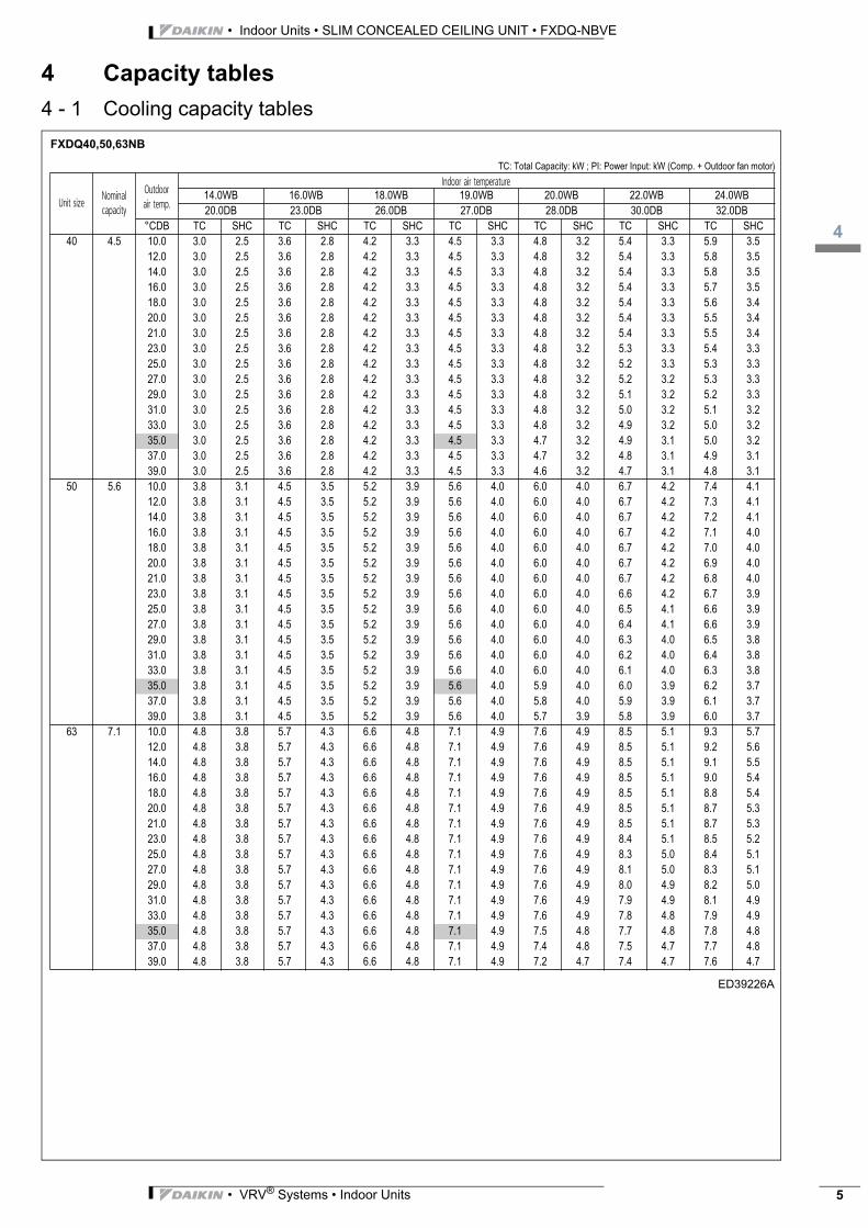
4 - 1 Cooling capacity tablesFXDQ40,50,63NB
ED39226A
.
14.0WB 16.0WB 18.0WB 19.0WB 20.0WB 22.0WB 24.0WB
20.0DB 23.0DB 26.0DB 27.0DB 28.0DB 30.0DB 32.0DB
°CDB TC SHC TC SHC TC SHC TC SHC TC SHC TC SHC TC SHC
40 4.5 10.0 3.0 2.5 3.6 2.8 4.2 3.3 4.5 3.3 4.8 3.2 5.4 3.3 5.9 3.5
12.0 3.0 2.5 3.6 2.8 4.2 3.3 4.5 3.3 4.8 3.2 5.4 3.3 5.8 3.5
14.0 3.0 2.5 3.6 2.8 4.2 3.3 4.5 3.3 4.8 3.2 5.4 3.3 5.8 3.5
16.0 3.0 2.5 3.6 2.8 4.2 3.3 4.5 3.3 4.8 3.2 5.4 3.3 5.7 3.5
18.0 3.0 2.5 3.6 2.8 4.2 3.3 4.5 3.3 4.8 3.2 5.4 3.3 5.6 3.4
20.0 3.0 2.5 3.6 2.8 4.2 3.3 4.5 3.3 4.8 3.2 5.4 3.3 5.5 3.4
21.0 3.0 2.5 3.6 2.8 4.2 3.3 4.5 3.3 4.8 3.2 5.4 3.3 5.5 3.4
23.0 3.0 2.5 3.6 2.8 4.2 3.3 4.5 3.3 4.8 3.2 5.3 3.3 5.4 3.3
25.0 3.0 2.5 3.6 2.8 4.2 3.3 4.5 3.3 4.8 3.2 5.2 3.3 5.3 3.3
27.0 3.0 2.5 3.6 2.8 4.2 3.3 4.5 3.3 4.8 3.2 5.2 3.2 5.3 3.3
29.0 3.0 2.5 3.6 2.8 4.2 3.3 4.5 3.3 4.8 3.2 5.1 3.2 5.2 3.3
31.0 3.0 2.5 3.6 2.8 4.2 3.3 4.5 3.3 4.8 3.2 5.0 3.2 5.1 3.2
33.0 3.0 2.5 3.6 2.8 4.2 3.3 4.5 3.3 4.8 3.2 4.9 3.2 5.0 3.2
35.0 3.0 2.5 3.6 2.8 4.2 3.3 4.5 3.3 4.7 3.2 4.9 3.1 5.0 3.2
37.0 3.0 2.5 3.6 2.8 4.2 3.3 4.5 3.3 4.7 3.2 4.8 3.1 4.9 3.1
39.0 3.0 2.5 3.6 2.8 4.2 3.3 4.5 3.3 4.6 3.2 4.7 3.1 4.8 3.1
50 5.6 10.0 3.8 3.1 4.5 3.5 5.2 3.9 5.6 4.0 6.0 4.0 6.7 4.2 7.4 4.1
12.0 3.8 3.1 4.5 3.5 5.2 3.9 5.6 4.0 6.0 4.0 6.7 4.2 7.3 4.1
14.0 3.8 3.1 4.5 3.5 5.2 3.9 5.6 4.0 6.0 4.0 6.7 4.2 7.2 4.1
16.0 3.8 3.1 4.5 3.5 5.2 3.9 5.6 4.0 6.0 4.0 6.7 4.2 7.1 4.0
18.0 3.8 3.1 4.5 3.5 5.2 3.9 5.6 4.0 6.0 4.0 6.7 4.2 7.0 4.0
20.0 3.8 3.1 4.5 3.5 5.2 3.9 5.6 4.0 6.0 4.0 6.7 4.2 6.9 4.0
21.0 3.8 3.1 4.5 3.5 5.2 3.9 5.6 4.0 6.0 4.0 6.7 4.2 6.8 4.0
23.0 3.8 3.1 4.5 3.5 5.2 3.9 5.6 4.0 6.0 4.0 6.6 4.2 6.7 3.9
25.0 3.8 3.1 4.5 3.5 5.2 3.9 5.6 4.0 6.0 4.0 6.5 4.1 6.6 3.9
27.0 3.8 3.1 4.5 3.5 5.2 3.9 5.6 4.0 6.0 4.0 6.4 4.1 6.6 3.9
29.0 3.8 3.1 4.5 3.5 5.2 3.9 5.6 4.0 6.0 4.0 6.3 4.0 6.5 3.8
31.0 3.8 3.1 4.5 3.5 5.2 3.9 5.6 4.0 6.0 4.0 6.2 4.0 6.4 3.8
33.0 3.8 3.1 4.5 3.5 5.2 3.9 5.6 4.0 6.0 4.0 6.1 4.0 6.3 3.8
35.0 3.8 3.1 4.5 3.5 5.2 3.9 5.6 4.0 5.9 4.0 6.0 3.9 6.2 3.7
37.0 3.8 3.1 4.5 3.5 5.2 3.9 5.6 4.0 5.8 4.0 5.9 3.9 6.1 3.7
39.0 3.8 3.1 4.5 3.5 5.2 3.9 5.6 4.0 5.7 3.9 5.8 3.9 6.0 3.7
63 7.1 10.0 4.8 3.8 5.7 4.3 6.6 4.8 7.1 4.9 7.6 4.9 8.5 5.1 9.3 5.7
12.0 4.8 3.8 5.7 4.3 6.6 4.8 7.1 4.9 7.6 4.9 8.5 5.1 9.2 5.6
14.0 4.8 3.8 5.7 4.3 6.6 4.8 7.1 4.9 7.6 4.9 8.5 5.1 9.1 5.5
16.0 4.8 3.8 5.7 4.3 6.6 4.8 7.1 4.9 7.6 4.9 8.5 5.1 9.0 5.4
18.0 4.8 3.8 5.7 4.3 6.6 4.8 7.1 4.9 7.6 4.9 8.5 5.1 8.8 5.4
20.0 4.8 3.8 5.7 4.3 6.6 4.8 7.1 4.9 7.6 4.9 8.5 5.1 8.7 5.3
21.0 4.8 3.8 5.7 4.3 6.6 4.8 7.1 4.9 7.6 4.9 8.5 5.1 8.7 5.3
23.0 4.8 3.8 5.7 4.3 6.6 4.8 7.1 4.9 7.6 4.9 8.4 5.1 8.5 5.2
25.0 4.8 3.8 5.7 4.3 6.6 4.8 7.1 4.9 7.6 4.9 8.3 5.0 8.4 5.1
27.0 4.8 3.8 5.7 4.3 6.6 4.8 7.1 4.9 7.6 4.9 8.1 5.0 8.3 5.1
29.0 4.8 3.8 5.7 4.3 6.6 4.8 7.1 4.9 7.6 4.9 8.0 4.9 8.2 5.0
31.0 4.8 3.8 5.7 4.3 6.6 4.8 7.1 4.9 7.6 4.9 7.9 4.9 8.1 4.9
33.0 4.8 3.8 5.7 4.3 6.6 4.8 7.1 4.9 7.6 4.9 7.8 4.8 7.9 4.9
35.0 4.8 3.8 5.7 4.3 6.6 4.8 7.1 4.9 7.5 4.8 7.7 4.8 7.8 4.8
37.0 4.8 3.8 5.7 4.3 6.6 4.8 7.1 4.9 7.4 4.8 7.5 4.7 7.7 4.8
39.0 4.8 3.8 5.7 4.3 6.6 4.8 7.1 4.9 7.2 4.7 7.4 4.7 7.6 4.7
TC: Total Capacity: kW ; PI: Power Input: kW (Comp. + Outdoor fan motor)
Unit sizeNominal capacity
Outdoor air temp.
Indoor air temperature
• VRV® Systems • Indoor Units 5
• Indoor Units • SLIM CONCEALED CEILING UNIT • FXDQ-NBVE
4
6
4 Capacity tables
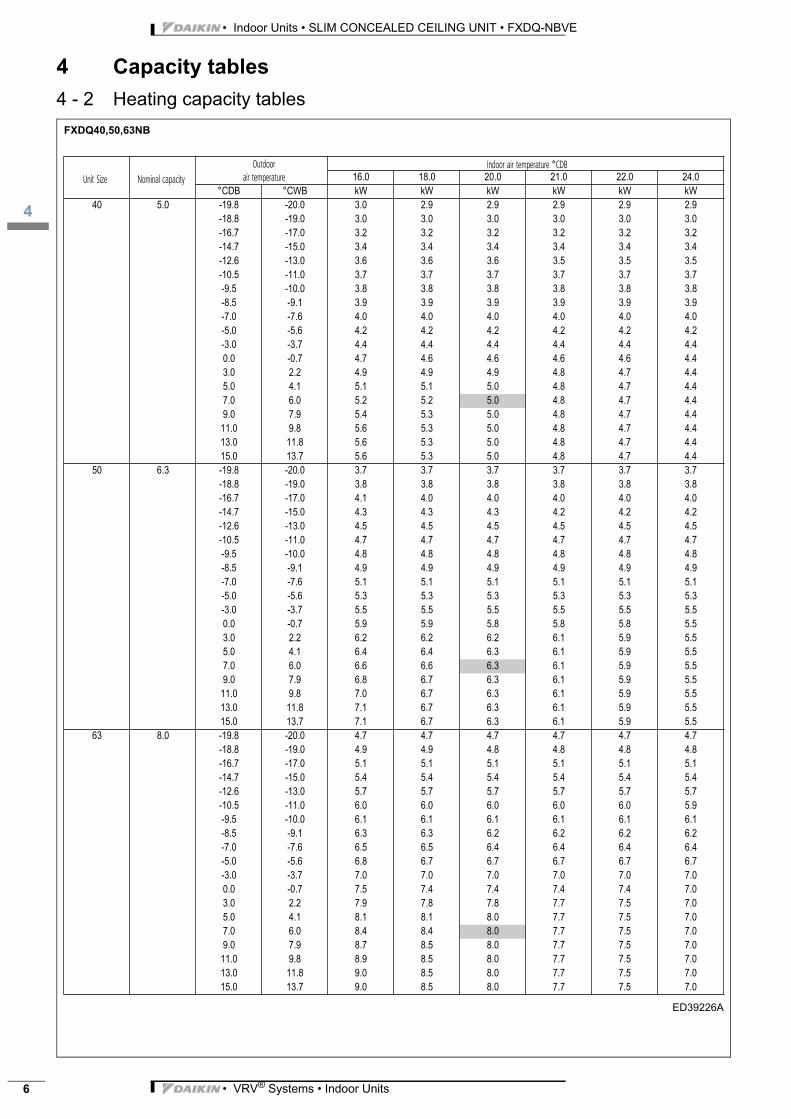
4 - 2 Heating capacity tablesFXDQ40,50,63NB
ED39226A
16.0 18.0 20.0 21.0 22.0 24.0
°CDB °CWB kW kW kW kW kW kW
40 5.0 -19.8 -20.0 3.0 2.9 2.9 2.9 2.9 2.9
-18.8 -19.0 3.0 3.0 3.0 3.0 3.0 3.0
-16.7 -17.0 3.2 3.2 3.2 3.2 3.2 3.2
-14.7 -15.0 3.4 3.4 3.4 3.4 3.4 3.4
-12.6 -13.0 3.6 3.6 3.6 3.5 3.5 3.5
-10.5 -11.0 3.7 3.7 3.7 3.7 3.7 3.7
-9.5 -10.0 3.8 3.8 3.8 3.8 3.8 3.8
-8.5 -9.1 3.9 3.9 3.9 3.9 3.9 3.9
-7.0 -7.6 4.0 4.0 4.0 4.0 4.0 4.0
-5.0 -5.6 4.2 4.2 4.2 4.2 4.2 4.2
-3.0 -3.7 4.4 4.4 4.4 4.4 4.4 4.4
0.0 -0.7 4.7 4.6 4.6 4.6 4.6 4.4
3.0 2.2 4.9 4.9 4.9 4.8 4.7 4.4
5.0 4.1 5.1 5.1 5.0 4.8 4.7 4.4
7.0 6.0 5.2 5.2 5.0 4.8 4.7 4.4
9.0 7.9 5.4 5.3 5.0 4.8 4.7 4.4
11.0 9.8 5.6 5.3 5.0 4.8 4.7 4.4
13.0 11.8 5.6 5.3 5.0 4.8 4.7 4.4
15.0 13.7 5.6 5.3 5.0 4.8 4.7 4.4
50 6.3 -19.8 -20.0 3.7 3.7 3.7 3.7 3.7 3.7
-18.8 -19.0 3.8 3.8 3.8 3.8 3.8 3.8
-16.7 -17.0 4.1 4.0 4.0 4.0 4.0 4.0
-14.7 -15.0 4.3 4.3 4.3 4.2 4.2 4.2
-12.6 -13.0 4.5 4.5 4.5 4.5 4.5 4.5
-10.5 -11.0 4.7 4.7 4.7 4.7 4.7 4.7
-9.5 -10.0 4.8 4.8 4.8 4.8 4.8 4.8
-8.5 -9.1 4.9 4.9 4.9 4.9 4.9 4.9
-7.0 -7.6 5.1 5.1 5.1 5.1 5.1 5.1
-5.0 -5.6 5.3 5.3 5.3 5.3 5.3 5.3
-3.0 -3.7 5.5 5.5 5.5 5.5 5.5 5.5
0.0 -0.7 5.9 5.9 5.8 5.8 5.8 5.5
3.0 2.2 6.2 6.2 6.2 6.1 5.9 5.5
5.0 4.1 6.4 6.4 6.3 6.1 5.9 5.5
7.0 6.0 6.6 6.6 6.3 6.1 5.9 5.5
9.0 7.9 6.8 6.7 6.3 6.1 5.9 5.5
11.0 9.8 7.0 6.7 6.3 6.1 5.9 5.5
13.0 11.8 7.1 6.7 6.3 6.1 5.9 5.5
15.0 13.7 7.1 6.7 6.3 6.1 5.9 5.5
63 8.0 -19.8 -20.0 4.7 4.7 4.7 4.7 4.7 4.7
-18.8 -19.0 4.9 4.9 4.8 4.8 4.8 4.8
-16.7 -17.0 5.1 5.1 5.1 5.1 5.1 5.1
-14.7 -15.0 5.4 5.4 5.4 5.4 5.4 5.4
-12.6 -13.0 5.7 5.7 5.7 5.7 5.7 5.7
-10.5 -11.0 6.0 6.0 6.0 6.0 6.0 5.9
-9.5 -10.0 6.1 6.1 6.1 6.1 6.1 6.1
-8.5 -9.1 6.3 6.3 6.2 6.2 6.2 6.2
-7.0 -7.6 6.5 6.5 6.4 6.4 6.4 6.4
-5.0 -5.6 6.8 6.7 6.7 6.7 6.7 6.7
-3.0 -3.7 7.0 7.0 7.0 7.0 7.0 7.0
0.0 -0.7 7.5 7.4 7.4 7.4 7.4 7.0
3.0 2.2 7.9 7.8 7.8 7.7 7.5 7.0
5.0 4.1 8.1 8.1 8.0 7.7 7.5 7.0
7.0 6.0 8.4 8.4 8.0 7.7 7.5 7.0
9.0 7.9 8.7 8.5 8.0 7.7 7.5 7.0
11.0 9.8 8.9 8.5 8.0 7.7 7.5 7.0
13.0 11.8 9.0 8.5 8.0 7.7 7.5 7.0
15.0 13.7 9.0 8.5 8.0 7.7 7.5 7.0
Unit Size Nominal capacityOutdoor
air temperatureIndoor air temperature °CDB
• VRV® Systems • Indoor Units
3
5
• Indoor Units • SLIM CONCEALED CEILING UNIT • FXDQ-NBVE
5 Dimensional drawing & centre of gravity
5 - 1 Dimensional drawingFXDQ-M9
3TW25512-2A
Unit Size Nominal capacityOutdoor
air temperatureIndoor air temperature °CDB
16.0 18.0 20.0 21.0 22.0 24.0°CDB °CWB kW kW kW kW kW kW
20 2.5 -19.8 -20.0 1.5 1.5 1.5 1.5 1.5 1.5 -18.8 -19.0 1.5 1.5 1.5 1.5 1.5 1.5 -16.7 -17.0 1.6 1.6 1.6 1.6 1.6 1.6 -14.7 -15.0 1.7 1.7 1.7 1.7 1.7 1.7 -12.6 -13.0 1.8 1.8 1.8 1.8 1.8 1.8 -10.5 -11.0 1.9 1.9 1.9 1.9 1.9 1.9 -9.5 -10.0 1.9 1.9 1.9 1.9 1.9 1.9 -8.5 -9.1 2.0 2.0 1.9 1.9 1.9 1.9 -7.0 -7.6 2.0 2.0 2.0 2.0 2.0 2.0 -5.0 -5.6 2.1 2.1 2.1 2.1 2.1 2.1 -3.0 -3.7 2.2 2.2 2.2 2.2 2.2 2.2 0.0 -0.7 2.3 2.3 2.3 2.3 2.3 2.2 3.0 2.2 2.5 2.5 2.4 2.4 2.3 2.2 5.0 4.1 2.5 2.5 2.5 2.4 2.3 2.2 7.0 6.0 2.6 2.6 2.5 2.4 2.3 2.2 9.0 7.9 2.7 2.7 2.5 2.4 2.3 2.2 11.0 9.8 2.8 2.7 2.5 2.4 2.3 2.2 13.0 11.8 2.8 2.7 2.5 2.4 2.3 2.2 15.0 13.7 2.8 2.7 2.5 2.4 2.3 2.2
25 3.2 -19.8 -20.0 1.9 1.9 1.9 1.9 1.9 1.9 -18.8 -19.0 1.9 1.9 1.9 1.9 1.9 1.9 -16.7 -17.0 2.1 2.1 2.0 2.0 2.0 2.0 -14.7 -15.0 2.2 2.2 2.2 2.2 2.2 2.1 -12.6 -13.0 2.3 2.3 2.3 2.3 2.3 2.3 -10.5 -11.0 2.4 2.4 2.4 2.4 2.4 2.4 -9.5 -10.0 2.5 2.4 2.4 2.4 2.4 2.4 -8.5 -9.1 2.5 2.5 2.5 2.5 2.5 2.5 -7.0 -7.6 2.6 2.6 2.6 2.6 2.6 2.6 -5.0 -5.6 2.7 2.7 2.7 2.7 2.7 2.7 -3.0 -3.7 2.8 2.8 2.8 2.8 2.8 2.8 0.0 -0.7 3.0 3.0 3.0 3.0 3.0 2.8 3.0 2.2 3.1 3.1 3.1 3.1 3.0 2.8 5.0 4.1 3.3 3.2 3.2 3.1 3.0 2.8 7.0 6.0 3.4 3.4 3.2 3.1 3.0 2.8 9.0 7.9 3.5 3.4 3.2 3.1 3.0 2.8 11.0 9.8 3.6 3.4 3.2 3.1 3.0 2.8 13.0 11.8 3.6 3.4 3.2 3.1 3.0 2.8 15.0 13.7 3.6 3.4 3.2 3.1 3.0 2.8
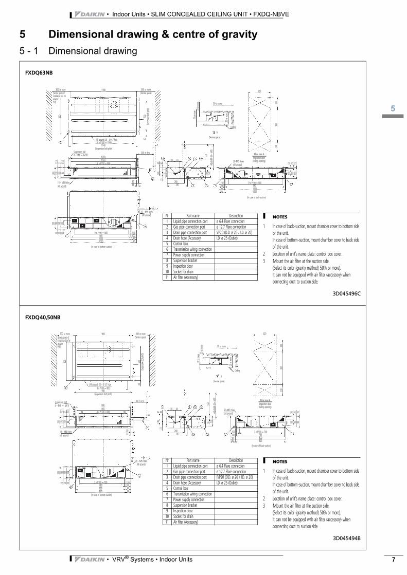
FXDQ63NB
3D045496C
300 or more 300 or more
300 or less
(Service space)
500
60
2347 90
100
50 170
550
Adjus
table
(0~60
0)
620
(Suspe
nsion
bolt p
itch)
1140
6 x P150 = 900
1080
30330
130 63
280
50 or more
620
Allow view AInspection door(Ceiling opening)20-M5 Holes
(All around)
(In case of back-suction)
9 x P100 = 9009801000
100
160
180
50 20 10
1020
1501009080
(Service space)
A
20 or
more
20 or
more
300
900
300
20 or
more
Ceiling
33
1301009080
9 x P100 = 90098010001020
(In case of bottom-suction)
80153
170
57.5
2112.5
20 501020
0
100
160
180
200
1060
10 x P100 = 1000(All around) 26 - Ø 4.7 hole
(All around)
(Suspension bolt pitch)Suspension bolt4 - M8 ~ M10
18 - M4 Holes
1100(Service space of installation box for adaptorPCB)
(All around)20 - M5 Holes
NOTES
1 In case of back-suction, mount chamber cover to bottom side of the unit.In case of bottom-suction, mount chamber cover to back side of the unit.
2 Location of unit’s name plate: control box cover.3 Mount the air filter at the suction side.
(Select its color (gravity method) 50% or more).It can not be equipped with air filter (accessory) when connecting duct to suction side.
Nr Part name Description1 Liquid pipe connection port ø 6.4 Flare connection2 Gas pipe connection port ø 12.7 Flare connection3 Drain pipe connection port VP20 (O.D. ø 26 / I.D. ø 20)4 Drain hose (Accessory) I.D. ø 25 (Outlet)5 Control box6 Transmission wiring connection7 Power supply connection8 Suspension bracket9 Inspection door10 Socket for drain11 Air filter (Accessory)
FXDQ40,50NB
3D045494B
300 or more 300 or more
300 or less
(Service space)
500
60
2347 90
100
50 170
550
Adjus
table
(0~60
0)
620
(Suspe
nsion
bolt p
itch)
940
4 x P150 = 600
880
9090
30330
130 63
280
50 or more
620
Allow view AInspection door(Ceiling opening)
20-M5 Holes(All around)
(In case of back-suction)
7 x P100 = 700780800
100
160
180
50 20 10
820
1501009080
(Service space)
A
20 or
more
20 or
more
300
900
300
20 or
more
Ceiling
33
1301009080
7 x P100 = 700780800820
(In case of bottom-suction)
80153
170
57.5
2112.5
20 501020
0
100
160
180
200
860
8 x P100 = 800(All around) 22 - Ø 4.7 hole
(All around)
(Suspension bolt pitch)
Suspension bolt4 - M8 ~ M10
18 - M4 Holes
900(Service space of installation box for adaptorPCB)
(All around)20 - M5 Holes NOTES
1 In case of back-suction, mount chamber cover to bottom side of the unit.In case of bottom-suction, mount chamber cover to back side of the unit.
2 Location of unit’s name plate: control box cover.3 Mount the air filter at the suction side.
(Select its color (gravity method) 50% or more).It can not be equipped with air filter (accessory) when connecting duct to suction side.
Nr Part name Description1 Liquid pipe connection port ø 6.4 Flare connection2 Gas pipe connection port ø 12.7 Flare connection3 Drain pipe connection port IVP20 (O.D. ø 26 / I.D. ø 20)4 Drain hose (Accessory) I.D. ø 25 (Outlet)5 Control box6 Transmission wiring connection7 Power supply connection8 Suspension bracket9 Inspection door10 Socket for drain11 Air filter (Accessory)
• VRV® Systems • Indoor Units 7
• Indoor Units • SLIM CONCEALED CEILING UNIT • FXDQ-NBVE
5
8
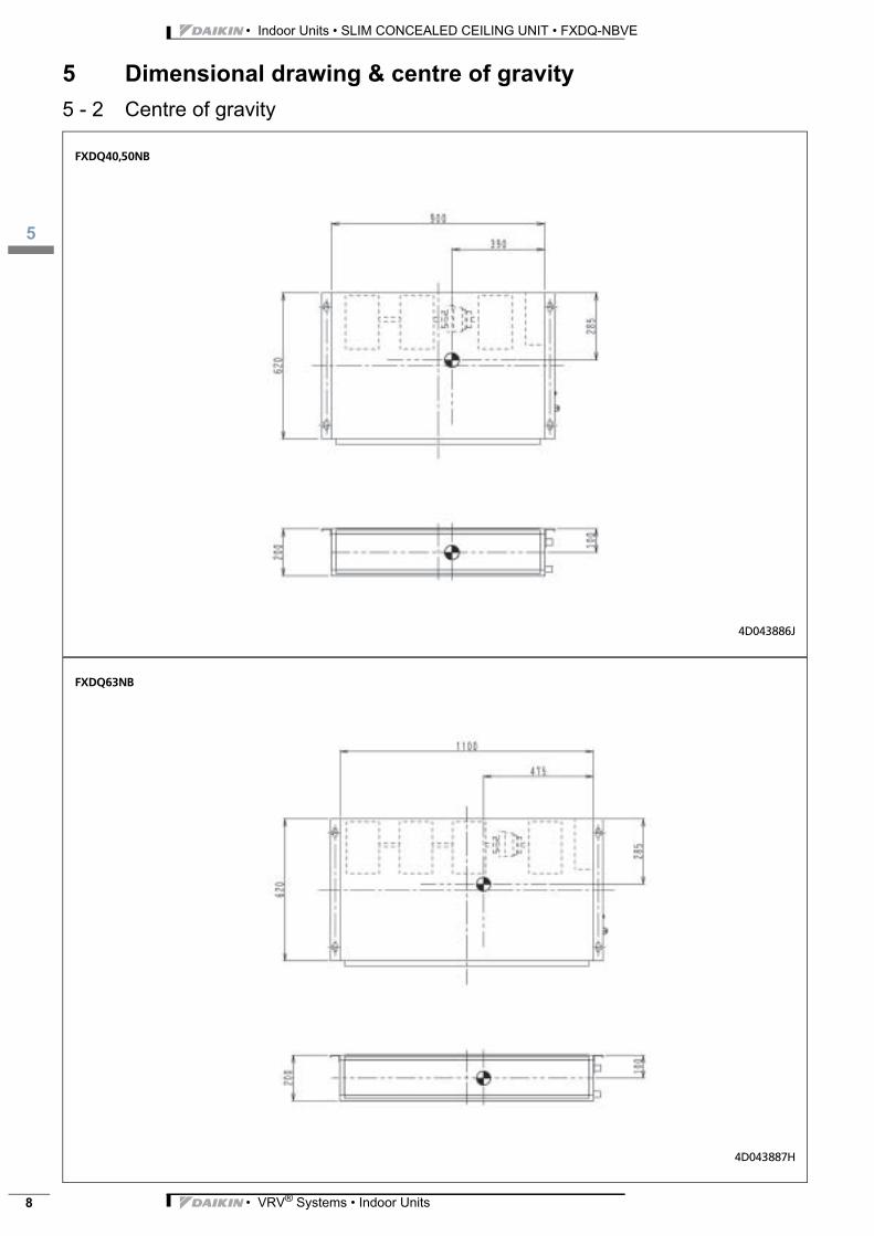
5 Dimensional drawing & centre of gravity
5 - 2 Centre of gravityFXDQ40,50NB
4D043886J
FXDQ63NB
4D043887H
• VRV® Systems • Indoor Units
3
6
• Indoor Units • SLIM CONCEALED CEILING UNIT • FXDQ-NBVE
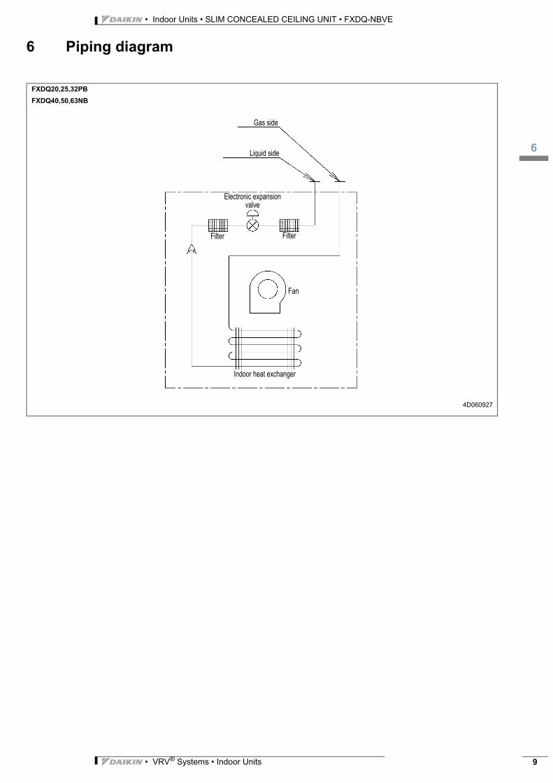
6 Piping diagram
FXDQ20,25,32PB
FXDQ40,50,63NB
4D060927
Gas side
Liquid side
Electronic expansion valve
Filter Filter
Indoor heat exchanger
Fan
• VRV® Systems • Indoor Units 9

• Indoor Units • SLIM CONCEALED CEILING UNIT • FXDQ-NBVE
7
10
7 Wiring diagram
7 - 1 Wiring diagramFXDQ20,25,32PB
FXDQ40,50,63NB
3D060547
NOTES
1 In case of using central remote control, connect it to the unit in accordance with the attached installation manual.
2 Remote control model varies according to the combination system, confirm enineering materials and catalogs, etc. before connecting.
3 When connecting the input wires from outside, forced off or on/off control operation can be selected by remote control.
In details, refer to the installation manual attached to the unit.
A1P Printed circuit board R1T Thermistor (air) Z1C•Z2C Noise filter (ferrite core)
C1 Capacitor (M1F) R2T Thermistor (coil - 1) Wired remote controlF1U Fuse (F5A, 250V) R3T Thermistor (coil - 2) R1T Thermistor (air)
HAP Light emitting diode (service monitor-green)
S1L Float switch SS1 Selector switch (main/sub)
T1R Transformer (220V/22V) Connector for optional partsKPR Magnetic relay (M1P) V1TR Phase control circuit X16A Connector (adapter for wiring)
M1F Motor (indoor fan) X1M Terminal block X18A Connector (wiring adapter for electrical appendices)M1P Motor (drain pump) X2M Terminal block
Q1M Thermal protector (M1F embedded) Y1E Electronic expansion valve
: Terminal Colors: BLK: Black ORG: Orange WHT: White
: Connector BLU: Blue PNK: Pink YLW: Yellow
: Field wiring GRY: Gray PRP: Purple
GRN: Green RED: Red
POWER SUPPLY
Note: 3Input from outside
Note: 1Transmission wiring central remote control
Wired remote control
Control box
,
• VRV® Systems • Indoor Units
3
8
• Indoor Units • SLIM CONCEALED CEILING UNIT • FXDQ-NBVE
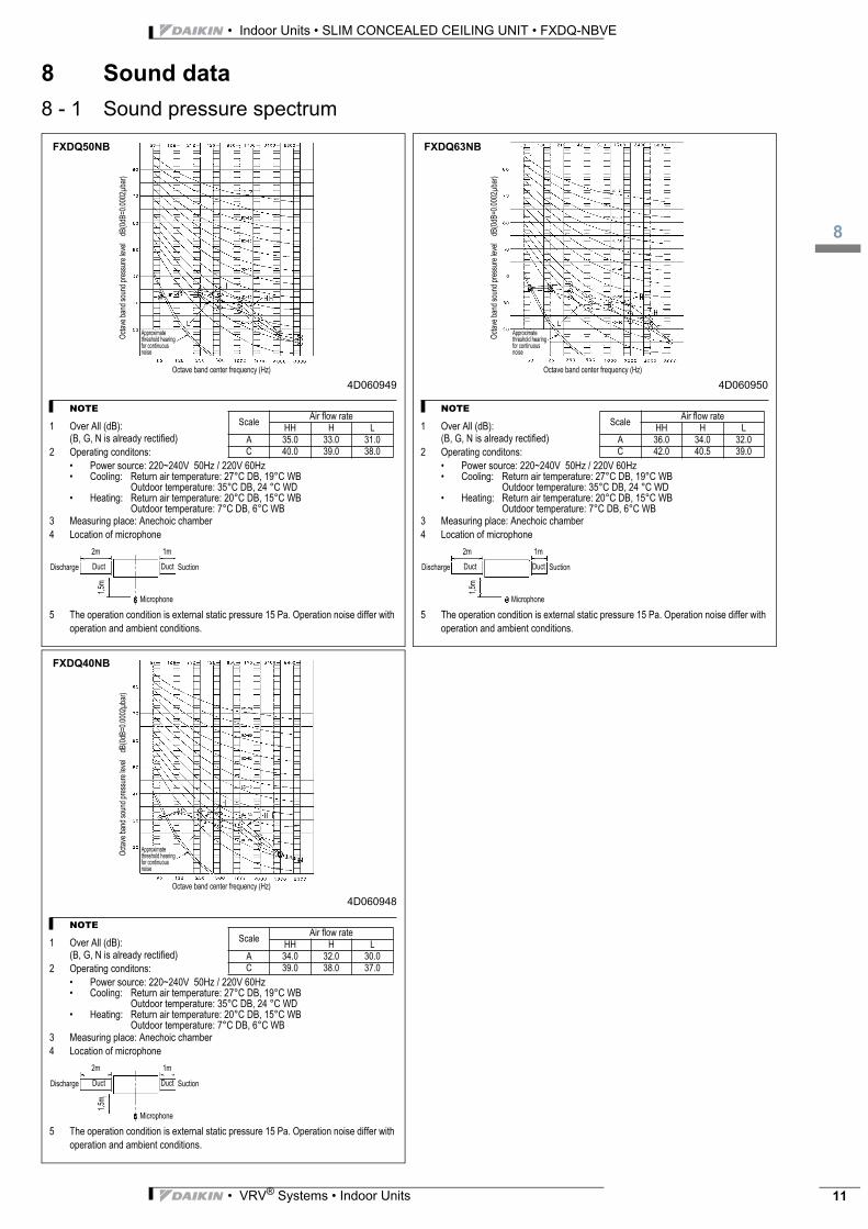
8 Sound data
8 - 1 Sound pressure spectrum4D060949
NOTE
1 Over All (dB):(B, G, N is already rectified)
2 Operating conditons:
• Power source: 220~240V 50Hz / 220V 60Hz• Cooling: Return air temperature: 27°C DB, 19°C WB
Outdoor temperature: 35°C DB, 24 °C WD• Heating: Return air temperature: 20°C DB, 15°C WB
Outdoor temperature: 7°C DB, 6°C WB3 Measuring place: Anechoic chamber
4 Location of microphone
5 The operation condition is external static pressure 15 Pa. Operation noise differ with
operation and ambient conditions.
Oct
ave
band
sou
nd p
ress
ure
leve
l d
B(0
dB=0
.000
2μba
r)
Octave band center frequency (Hz)
Approximate threshold hearing for continuous noise
FXDQ50NB
ScaleAir flow rate
HH H L
A 35.0 33.0 31.0C 40.0 39.0 38.0
Discharge SuctionDuctDuct
1m2m
1,5m
Microphone
4D060950
NOTE
1 Over All (dB):(B, G, N is already rectified)
2 Operating conditons:
• Power source: 220~240V 50Hz / 220V 60Hz• Cooling: Return air temperature: 27°C DB, 19°C WB
Outdoor temperature: 35°C DB, 24 °C WD• Heating: Return air temperature: 20°C DB, 15°C WB
Outdoor temperature: 7°C DB, 6°C WB3 Measuring place: Anechoic chamber
4 Location of microphone
5 The operation condition is external static pressure 15 Pa. Operation noise differ with
operation and ambient conditions.
Oct
ave
band
sou
nd p
ress
ure
leve
l d
B(0
dB=0
.000
2μba
r)
Octave band center frequency (Hz)
Approximate threshold hearing for continuous noise
FXDQ63NB
ScaleAir flow rate
HH H L
A 36.0 34.0 32.0C 42.0 40.5 39.0
Discharge SuctionDuctDuct
1m2m
1,5m
Microphone
4D060948
NOTE
1 Over All (dB):(B, G, N is already rectified)
2 Operating conditons:
• Power source: 220~240V 50Hz / 220V 60Hz• Cooling: Return air temperature: 27°C DB, 19°C WB
Outdoor temperature: 35°C DB, 24 °C WD• Heating: Return air temperature: 20°C DB, 15°C WB
Outdoor temperature: 7°C DB, 6°C WB3 Measuring place: Anechoic chamber
4 Location of microphone
5 The operation condition is external static pressure 15 Pa. Operation noise differ with
operation and ambient conditions.
Oct
ave
band
sou
nd p
ress
ure
leve
l d
B(0
dB=0
.000
2μba
r)
Octave band center frequency (Hz)
Approximate threshold hearing for continuous noise
FXDQ40NB
ScaleAir flow rate
HH H L
A 34.0 32.0 30.0C 39.0 38.0 37.0
Discharge SuctionDuctDuct
1m2m
1,5m
Microphone
• VRV® Systems • Indoor Units 11
• Indoor Units • SLIM CONCEALED CEILING UNIT • FXDQ-NBVE
9
12
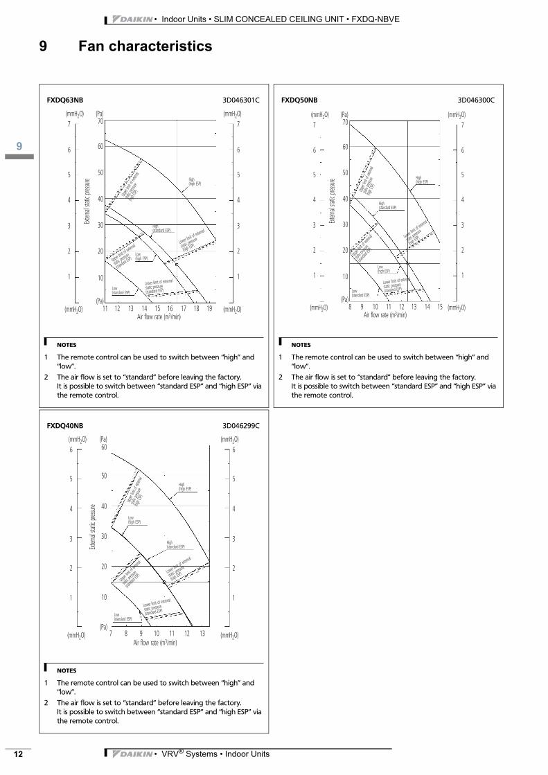
9 Fan characteristics
NOTES
1 The remote control can be used to switch between “high” and “low”.
2 The air flow is set to “standard” before leaving the factory.It is possible to switch between “standard ESP” and “high ESP” via the remote control.
FXDQ63NB 3D046301C
(mmH2O)
(mmH2O)
(Pa)
11 12 13 14 15 16 17 18 19
(mmH2O)
(mmH2O)
7
6
5
4
3
2
1
7
6
5
4
3
2
1
60
70
50
40
30
20
10
(Pa)
High(standard ESP)
Upper lim
it of exter
nal
static pres
sure
(standard
ESP)
Lower limit of external
static pressure(standard ESP)
Upper
limit o
f exte
rnal
static
pressu
re (hig
h ESP)
Lower limit of e
xternal
static pressu
re
(high ESP)
Low(standard ESP)
Low(high ESP)
High(high ESP)
Air flow rate (m3/min)
Extern
al sta
tic pre
ssure
NOTES
1 The remote control can be used to switch between “high” and “low”.
2 The air flow is set to “standard” before leaving the factory.It is possible to switch between “standard ESP” and “high ESP” via the remote control.
FXDQ50NB 3D046300C
(mmH2O)
(mmH2O)
(Pa)
8 9 10 11 12 13 14 15
(mmH2O)
(mmH2O)
7
6
5
4
3
2
1
7
6
5
4
3
2
1
60
70
50
40
30
20
10
(Pa)
High(standard ESP)
Upper l
imit of
externa
l
static p
ressure
(standa
rd ESP)
Lower limit of external
static pressure (standard ESP)
Upper
limit o
f exte
rnal
static
pressu
re (hig
h ESP)
Lower lim
it of exte
rnal
static pre
ssure
(high ESP
)
Low(standard ESP)
Low(high ESP)
High(high ESP)
Air flow rate (m3/min)
Extern
al sta
tic pre
ssure
NOTES
1 The remote control can be used to switch between “high” and “low”.
2 The air flow is set to “standard” before leaving the factory.It is possible to switch between “standard ESP” and “high ESP” via the remote control.
FXDQ40NB 3D046299C
(mmH2O)
(mmH2O)
(Pa)
7 8 9 10 11 12 13
6
5
4
3
2
1
(mmH2O)
(mmH2O)
6
5
4
3
2
1
60
50
40
30
20
10
(Pa)
High(standard ESP)
Upper li
mit of ex
ternal
static p
ressure
(standa
rd ESP)
Lower limit of external
static pressure
(standard ESP)
Upper
limit o
f exte
rnal
static
pressu
re(hig
h ESP)
Lower limit of
external
static pres
sure
(high ESP)
Low(standard ESP)
Low(high ESP)
High(high ESP)
Air flow rate (m3/min)
Extern
al sta
tic pre
ssure
• VRV® Systems • Indoor Units
Daikin Europe N.V. is approved by LRQA for its QualityManagement System in accordance with the ISO9001standard. ISO9001 pertains to quality assurance regardingdesign, development, manufacturing as well as to servicesrelated to the product.
Daikin units comply with the European regulations thatguarantee the safety of the product.
Prep
ared
in B
elgium
by La
nnoo
(ww
w.lan
noop
rint.b
e), a
comp
any w
hose
conc
ern f
or
the en
viron
mont
is se
t in th
e EMA
S an
d ISO
1400
1 sys
tems.
Resp
onsib
le Ed
itor:
Daiki
n Eur
ope N
.V., Z
andv
oord
estra
at 30
0, B-
8400
Oos
tende
The present publication is drawn up by way of information only and does notconstitute an offer binding upon Daikin Europe N.V.. Daikin Europe N.V. hascompiled the content of this publication to the best of its knowledge. Noexpress or implied warranty is given for the completeness, accuracy,reliability or fitness for particular purpose of its content and the products andservices presented therein. Specifications are subject to change withoutprior notice. Daikin Europe N.V. explicitly rejects any liability for any direct orindirect damage, in the broadest sense, arising from or related to the useand/or interpretation of this publication. All content is copyrighted by DaikinEurope N.V..
VRV® products are not within the scope of the Euroventcertification programme.
Naamloze VennootschapZandvoordestraat 300B-8400 Oostende, Belgiumwww.daikin.euBTW: BE 0412 120 336RPR Oostende
Daikin’s unique position as a manufacturer of airconditioning equipment, compressors andrefrigerants has led to its close involvement inenvironmental issues. For several years Daikin hashad the intension to become a leader in the provisionof products that have limited impact on theenvironment. This challenge demands the eco designand development of a wide range of products and anenergy management system, resulting in energyconservation and a reduction of waste.
ISO14001 assures an effective environmentalmanagement system in order to help protect human healthand the environment from the potential impact of ouractivities, products and services and to assist inmaintaining and improving the quality of the environment.