EEDEN09-403 - cdvdpacking · 2013-11-12 · EUWA*5-24KAZW EEDEN09-403 Applied Systems. Air-cooled...
48
technical data Air-cooled EUWA*5-24KAZW EEDEN09-403 Applied Systems
-
Upload
truongquynh -
Category
Documents
-
view
215 -
download
0
Transcript of EEDEN09-403 - cdvdpacking · 2013-11-12 · EUWA*5-24KAZW EEDEN09-403 Applied Systems. Air-cooled...
technical data
Air-cooled
EUWA*5-24KAZW
EEDEN09-403
Applied System
s
Air-cooled
EUWA*5-24KAZW
EED
EN09
-403
- 12
/200
8Pr
inte
d in
Bel
gium
by
Goe
kint
Gra
phic
sCo
pyrig
ht ©
Dai
kin
EEDEN09- 403
Naamloze Vennootschap
Zandvoordestraat 300
B-8400 Ostend, Belgium
www.daikin.eu
BTW: BE 0412 120 336
RPR Oostende
ISO14001 assures an effective environmental management system in order to help protect human health and the environment from potential impact of our activities, products and services and to assist in maintaining and improving the quality of the environment.
Daikin Europe N.V. is approved by LRQA for its Quality Management System in accordance with the ISO9001 standard. ISO9001 pertains to quality assurance regarding design, development, manufacturing as well as to services related to the product.
Daikin units comply with the European regulations that guarantee the safety of the product.
Daikin Europe N.V. participates in the Eurovent Certification Programme for Air Conditioners (AC), Liquid Chilling Packages (LCP) and Fan Coil units (FC); the certified data of certified models are listed in the Eurovent Directory.
Daikin’s unique position as a man-ufacturer of air conditioning equip-ment, compressors and refrige-rants has led to its close involve-ment in environmental issues. Forseveral years Daikin has had the in-tention to become a leader in theprovision of products that havelimited impact on the environ-ment. This challenge demands theeco design and development of awide range of products and an en-ergy management system, result-ing in energy conservation and areduction of waste.
“The present publication is drawn up by way of information only anddoes not constitute an offer binding upon Daikin Europe N.V.. DaikinEurope N.V. has compiled the content of this publication to the bestof its knowledge. No express or implied warranty is given for thecompleteness, accuracy, reliability or fitness for particular purpose ofits content and the products and services presented therein. Specifi-cations are subject to change without prior notice. Daikin Europe N.V.explicitly rejects any liability for any direct or indirect damage, In thebroadest sense, arising from or related to the use and/or interpreta-tion of this publication. All content is copyrighted by Daikin EuropeN.V..”
technical data
Air-cooled
EUWA*5-24KAZW
EEDEN09-403
Applied System
s
• Chillers • R-407C • EUWA-KAZW
• Applied Systems • Chillers4
Chille Applie EUWA-KA R-407C
Cooling only
Heating only
Heat pump

• Applied Systems • Chillers 5
• Chillers • R-407C • EUWA-KAZW
TABLE OF CONTENTSEUWA-KAZW
1 Features . . . . . . . . . . . . . . . . . . . . . . . . . . . . . . . . . . . . . . . . . . . . . . . . . . . . . . . . . . . . . 6
2 Specification text . . . . . . . . . . . . . . . . . . . . . . . . . . . . . . . . . . . . . . . . . . . . . . . . . . . 7
3 Specifications . . . . . . . . . . . . . . . . . . . . . . . . . . . . . . . . . . . . . . . . . . . . . . . . . . . . . . . 9 Technical Specifications . . . . . . . . . . . . . . . . . . . . . . . . . . . . . . . . . . . . . . . . . . . . . 9 Electrical Specifications . . . . . . . . . . . . . . . . . . . . . . . . . . . . . . . . . . . . . . . . . . . . 14
4 Options . . . . . . . . . . . . . . . . . . . . . . . . . . . . . . . . . . . . . . . . . . . . . . . . . . . . . . . . . . . . . 17
5 Control systems . . . . . . . . . . . . . . . . . . . . . . . . . . . . . . . . . . . . . . . . . . . . . . . . . . . 18
6 Capacity tables . . . . . . . . . . . . . . . . . . . . . . . . . . . . . . . . . . . . . . . . . . . . . . . . . . . . 19Cooling capacity tables . . . . . . . . . . . . . . . . . . . . . . . . . . . . . . . . . . . . . . . . . . . . . 19Capacity correction factor . . . . . . . . . . . . . . . . . . . . . . . . . . . . . . . . . . . . . . . . . . . 26
7 Dimensional drawing & centre of gravity . . . . . . . . . . . . . . . . . . . . . . . 27Dimensional drawing . . . . . . . . . . . . . . . . . . . . . . . . . . . . . . . . . . . . . . . . . . . . . . . . 27Centre of gravity . . . . . . . . . . . . . . . . . . . . . . . . . . . . . . . . . . . . . . . . . . . . . . . . . . . . 33
8 Piping diagram. . . . . . . . . . . . . . . . . . . . . . . . . . . . . . . . . . . . . . . . . . . . . . . . . . . . . 35
9 Wiring diagram. . . . . . . . . . . . . . . . . . . . . . . . . . . . . . . . . . . . . . . . . . . . . . . . . . . . . 36Wiring diagram . . . . . . . . . . . . . . . . . . . . . . . . . . . . . . . . . . . . . . . . . . . . . . . . . . . . . . 36
10 Sound data . . . . . . . . . . . . . . . . . . . . . . . . . . . . . . . . . . . . . . . . . . . . . . . . . . . . . . . . . 38Sound power spectrum . . . . . . . . . . . . . . . . . . . . . . . . . . . . . . . . . . . . . . . . . . . . . 38
11 Installation . . . . . . . . . . . . . . . . . . . . . . . . . . . . . . . . . . . . . . . . . . . . . . . . . . . . . . . . . . 39Water charge, flow and quality . . . . . . . . . . . . . . . . . . . . . . . . . . . . . . . . . . . . . . 39
12 Operation range . . . . . . . . . . . . . . . . . . . . . . . . . . . . . . . . . . . . . . . . . . . . . . . . . . . 40
13 Hydraulic performance. . . . . . . . . . . . . . . . . . . . . . . . . . . . . . . . . . . . . . . . . . . . 41Water pressure drop curve evaporator . . . . . . . . . . . . . . . . . . . . . . . . . . . . . . 41Water pressure drop curve unit . . . . . . . . . . . . . . . . . . . . . . . . . . . . . . . . . . . . . 43Static pressure pump . . . . . . . . . . . . . . . . . . . . . . . . . . . . . . . . . . . . . . . . . . . . . . . 45Static pressure unit . . . . . . . . . . . . . . . . . . . . . . . . . . . . . . . . . . . . . . . . . . . . . . . . . . 46

• Chillers • R-407C • EUWA-KAZW
• Applied Systems • Chillers6
1 Features
11
Chillers Applied Sys EUWA-KAZW R-407C • Optimised for use with R-407C
• Daikin scroll compressor
• Reduced installation time thanks to integrated pump and/or buffer tank
• Possibility for a 200 l buffer tank (KAZ-series)
• Low operating sound level
• Improved serviceability
• Main switch
• Water flow switch
• 3 different design options available
• EUWAB chiller with integrated hydraulic module (buffer tank, pump, expansion vessel, hydraulic components)
• EUWAN chiller without integrated hydraulic module
• EUWAP chiller with integrated hydraulic module (pump, expansion vessel, hydraulic components)
• Applied Systems • Chillers 7
• Chillers • R-407C • EUWA-KAZW
2 Specification text
3
12
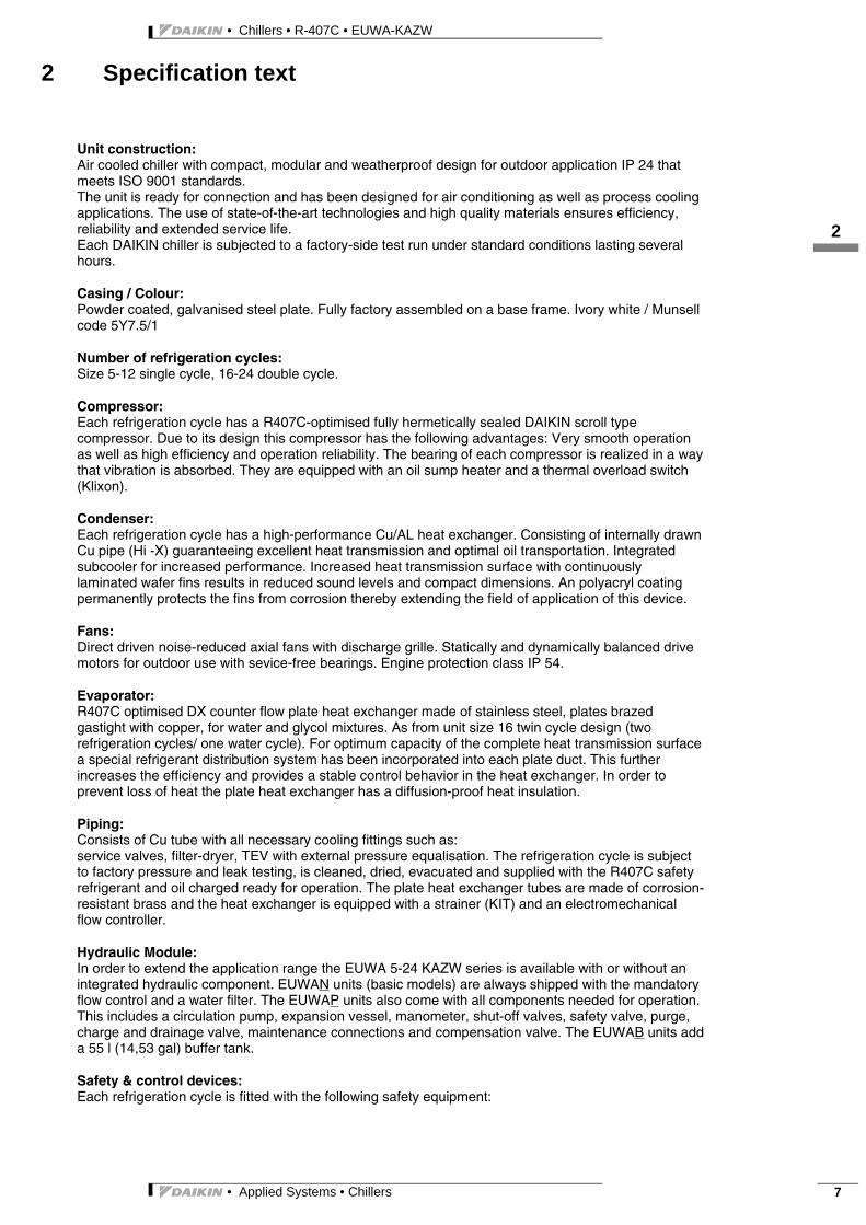
Unit construction: Air cooled chiller with compact, modular and weatherproof design for outdoor application IP 24 that meets ISO 9001 standards. The unit is ready for connection and has been designed for air conditioning as well as process cooling applications. The use of state-of-the-art technologies and high quality materials ensures efficiency, reliability and extended service life. Each DAIKIN chiller is subjected to a factory-side test run under standard conditions lasting several hours.
Casing / Colour: Powder coated, galvanised steel plate. Fully factory assembled on a base frame. Ivory white / Munsell code 5Y7.5/1
Number of refrigeration cycles: Size 5-12 single cycle, 16-24 double cycle.
Compressor: Each refrigeration cycle has a R407C-optimised fully hermetically sealed DAIKIN scroll type compressor. Due to its design this compressor has the following advantages: Very smooth operation as well as high efficiency and operation reliability. The bearing of each compressor is realized in a way that vibration is absorbed. They are equipped with an oil sump heater and a thermal overload switch (Klixon).
Condenser: Each refrigeration cycle has a high-performance Cu/AL heat exchanger. Consisting of internally drawn Cu pipe (Hi -X) guaranteeing excellent heat transmission and optimal oil transportation. Integrated subcooler for increased performance. Increased heat transmission surface with continuously laminated wafer fins results in reduced sound levels and compact dimensions. An polyacryl coating permanently protects the fins from corrosion thereby extending the field of application of this device.
Fans:Direct driven noise-reduced axial fans with discharge grille. Statically and dynamically balanced drive motors for outdoor use with sevice-free bearings. Engine protection class IP 54.
Evaporator: R407C optimised DX counter flow plate heat exchanger made of stainless steel, plates brazed gastight with copper, for water and glycol mixtures. As from unit size 16 twin cycle design (two refrigeration cycles/ one water cycle). For optimum capacity of the complete heat transmission surface a special refrigerant distribution system has been incorporated into each plate duct. This further increases the efficiency and provides a stable control behavior in the heat exchanger. In order to prevent loss of heat the plate heat exchanger has a diffusion-proof heat insulation.
Piping:Consists of Cu tube with all necessary cooling fittings such as: service valves, filter-dryer, TEV with external pressure equalisation. The refrigeration cycle is subject to factory pressure and leak testing, is cleaned, dried, evacuated and supplied with the R407C safety refrigerant and oil charged ready for operation. The plate heat exchanger tubes are made of corrosion-resistant brass and the heat exchanger is equipped with a strainer (KIT) and an electromechanical flow controller.
Hydraulic Module: In order to extend the application range the EUWA 5-24 KAZW series is available with or without an integrated hydraulic component. EUWAN units (basic models) are always shipped with the mandatory flow control and a water filter. The EUWAP units also come with all components needed for operation. This includes a circulation pump, expansion vessel, manometer, shut-off valves, safety valve, purge, charge and drainage valve, maintenance connections and compensation valve. The EUWAB units add a 55 l (14,53 gal) buffer tank.
Safety & control devices: Each refrigeration cycle is fitted with the following safety equipment:

• Chillers • R-407C • EUWA-KAZW
• Applied Systems • Chillers8
2 Specification text
12
High/low pressure switches, hot gas temperature control, thermal protection for compressor and fan motor, overcurrent relay, freeze-up protection and evaporator heater. Each refrigeration cycle is provided with the following control components: Electronic temperature monitoring, phase-sequence relay, timing safety device and switch frequency limiter.
Switching and control device: The control cabinet complies with applicable EC directives (CE) and fulfills the safety class IP 54. It contains a fully automatic DDC control and all necessary switching and control devices such as: Power switch, load, auxiliary and control cut-outs, transformers, control fuses, relay and auxiliary relay, sensors, and DDC controller.
The electronics have an automatic restart after power failure and provide the following digital inputs and outputs hard-wired to terminals for incorporating the GLT:
Digital inputs: Flow controller Pump contactor REMOTE ON/OFF
Digital outputs: Collective malfunction message Gen. operating message Operating message per compressor Cold water control
DDC control: The EUWA KAZW units are supplied with a digital controller that allows for a user friendly set-up, operation and maintenance of the unit. The controller consists of a numerical display, 4 control keys and 4 LEDs.
The electronics support for example the following functions:
3-step evaporator pressure control (winter control down to 5,00 °F ambient temperature) Allocation of the target value and the switching hysteresis Cold water return flow control Setting pump lead and lag times Setting maintenance intervalls Display of current operation parameters such as flow and return flow temperatures Recording of operating hours (compressor / pump) Error code retrieval Password protection
Optional This chiller can be fitted with an interface for integration into a Building Management System (BMS), which either supports the MODbus / J-bus or BACnet protocol.

• Applied Systems • Chillers 9
• Chillers • R-407C • EUWA-KAZW
3 Specifications
3
13
3-1 TECHNICAL SPECIFICATIONS EUWAN5KAZW1 EUWAP5KAZW1 EUWAB5KAZW1 EUWAN8KAZW1 EUWAP8KAZW1 EUWAB8KAZW1
Capacity (Eurovent)
Cooling Nominal kW 11.30 11.30 11.30 17.90 17.90 17.90
Capacity Steps % 0-100Nominal input (Eurovent)
Cooling kW 4.52 4.64 4.64 7.38 7.39 7.39
Casing Colour Ivory white/Munsell code 5Y7.5/1Material Polyester coated galvanised steel
Dimensions Unit Height mm 1230 1230 1230 1230 1230 1230Width mm 1290 1290 1290 1290 1290 1290Depth mm 734 734 734 734 734 734
Weight Unit kg 150 168 180 215 229 241Operating Weight kg 152 171 239 218 232 300
Air heat exchanger
Type Cross fin coil/Hi-X tubes and PE coated waffle louvre finsRows 2 2 2 2 2 2Stages 40 40 40 40 40 40Fin Pitch mm 2.00 2.00 2.00 2.00 2.00 2.00Face Area m² 1.57 1.57 1.57 1.57 1.57 1.57
Water Heat Exchanger Evaporator
Type Brased plateMinimum water volume in the system
l 54 54 54 85 85 85
Water flow rate Min l/min 16 16 16 26 26 26Nominal l/min 32 32 32 51 51 51Max l/min 65 65 65 102 102 102
Insulation material ClimaflexModel Quantity 1 1 1 1 1 1
Model AC50-24HX AC50-24HX AC50-24HX AC50-34HX AC50-34HX AC50-34HXPump Type
-
Horizontal multi-stage end-
suction
Horizontal multi-stage end-
suction
-
Horizontal multi-stage end-
suction
Horizontal multi-stage end-
suctionQuantity 1 1 1 1Model CH4-30 CH4-30 CH4-30 CH4-30Nominal static height pump
Heating kPa 238 238 216 216
Nominal static height unit
Heating kPa 205 205 154 154
Hydraulic components
Buffer tank volume l - 55 - 55Unit water volume l 2 3 59 3 3 59Safety valve bar - 3 3 - 3 3
Fan Drive Direct driveNominal air flow m³/min 160.00 160.00 160.00 170.00 170.00 170.00Model Quantity 2 2 2 1 1 1
Motor Output
W 140 140 140 190 190 190
Discharge direction VerticalQuantity
-
1 1 1Motor Output
W 230 230 230
Discharge direction Vertical Vertical VerticalCompressor Type Hermetically sealed scroll compressor
Refrigerant oil type Daphne FVC68DRefrigerant oil charge l 1.5 1.5 1.5 2.7 2.7 2.7Model Quantity 1 1 1 1 1 1
Model JT140BF-YE JT140BF-YE JT140BF-YE JT212DA-YE JT212DA-YE JT212DA-YESpeed rpm 2900 2900 2900 2900 2900 2900
Sound level Sound Power Cooling dBA 67 67 67 76 76 76Refrigerant circuit
Refrigerant type R-407CRefrigerant charge kg 3.9 3.9 3.9 4.6 4.6 4.6No of circuits 1 1 1 1 1 1Refrigerant control Thermostatic expansion valve
• Chillers • R-407C • EUWA-KAZW
• Applied Systems • Chillers10
3 Specifications
13
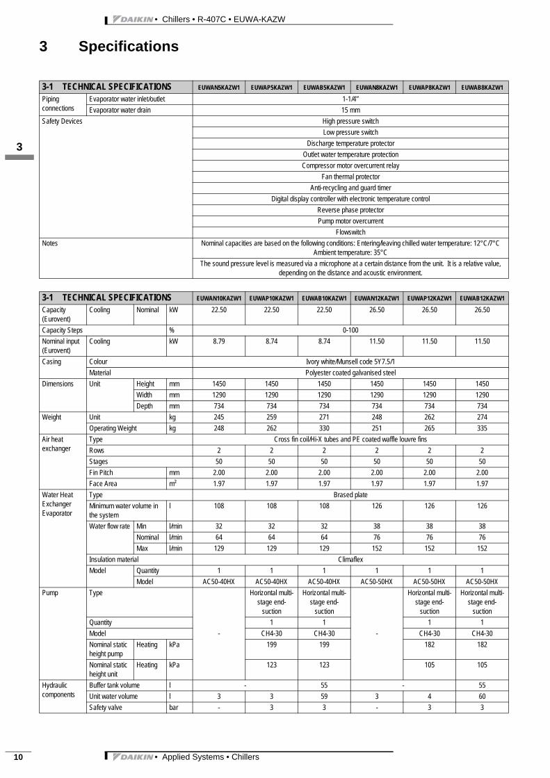
Piping connections
Evaporator water inlet/outlet 1-1/4’’Evaporator water drain 15 mm
Safety Devices High pressure switchLow pressure switch
Discharge temperature protectorOutlet water temperature protectionCompressor motor overcurrent relay
Fan thermal protectorAnti-recycling and guard timer
Digital display controller with electronic temperature controlReverse phase protectorPump motor overcurrent
FlowswitchNotes Nominal capacities are based on the following conditions: Entering/leaving chilled water temperature: 12°C/7°C
Ambient temperature: 35°CThe sound pressure level is measured via a microphone at a certain distance from the unit. It is a relative value,
depending on the distance and acoustic environment.
3-1 TECHNICAL SPECIFICATIONS EUWAN10KAZW1 EUWAP10KAZW1 EUWAB10KAZW1 EUWAN12KAZW1 EUWAP12KAZW1 EUWAB12KAZW1
Capacity (Eurovent)
Cooling Nominal kW 22.50 22.50 22.50 26.50 26.50 26.50
Capacity Steps % 0-100Nominal input (Eurovent)
Cooling kW 8.79 8.74 8.74 11.50 11.50 11.50
Casing Colour Ivory white/Munsell code 5Y7.5/1Material Polyester coated galvanised steel
Dimensions Unit Height mm 1450 1450 1450 1450 1450 1450Width mm 1290 1290 1290 1290 1290 1290Depth mm 734 734 734 734 734 734
Weight Unit kg 245 259 271 248 262 274Operating Weight kg 248 262 330 251 265 335
Air heat exchanger
Type Cross fin coil/Hi-X tubes and PE coated waffle louvre finsRows 2 2 2 2 2 2Stages 50 50 50 50 50 50Fin Pitch mm 2.00 2.00 2.00 2.00 2.00 2.00Face Area m² 1.97 1.97 1.97 1.97 1.97 1.97
Water Heat Exchanger Evaporator
Type Brased plateMinimum water volume in the system
l 108 108 108 126 126 126
Water flow rate Min l/min 32 32 32 38 38 38Nominal l/min 64 64 64 76 76 76Max l/min 129 129 129 152 152 152
Insulation material ClimaflexModel Quantity 1 1 1 1 1 1
Model AC50-40HX AC50-40HX AC50-40HX AC50-50HX AC50-50HX AC50-50HXPump Type
-
Horizontal multi-stage end-
suction
Horizontal multi-stage end-
suction
-
Horizontal multi-stage end-
suction
Horizontal multi-stage end-
suctionQuantity 1 1 1 1Model CH4-30 CH4-30 CH4-30 CH4-30Nominal static height pump
Heating kPa 199 199 182 182
Nominal static height unit
Heating kPa 123 123 105 105
Hydraulic components
Buffer tank volume l - 55 - 55Unit water volume l 3 3 59 3 4 60Safety valve bar - 3 3 - 3 3
3-1 TECHNICAL SPECIFICATIONS EUWAN5KAZW1 EUWAP5KAZW1 EUWAB5KAZW1 EUWAN8KAZW1 EUWAP8KAZW1 EUWAB8KAZW1

• Applied Systems • Chillers 11
• Chillers • R-407C • EUWA-KAZW
3 Specifications
3
13
Fan Drive Direct driveNominal air flow m³/min 170.00 170.00 170.00 170.00 170.00 170.00Model Quantity 1 1 1 1 1 1
Motor Output
W 190 190 190 190 190 190
Discharge direction VerticalQuantity 1 1 1 1 1 1Motor Output
W 230 230 230 230 230 230
Discharge direction VerticalCompressor Type Hermetically sealed scroll compressor
Refrigerant oil type Daphne FVC68DRefrigerant oil charge l 2.7 2.7 2.7 2.7 2.7 2.7Model Quantity 1 1 1 1 1 1
Model JT265DA-YE JT265DA-YE JT265DA-YE JT335DA-YE JT335DA-YE JT335DA-YESpeed rpm 2900 2900 2900 2900 2900 2900
Sound level Sound Power Cooling dBA 78 78 78 78 78 78Refrigerant circuit
Refrigerant type R-407CRefrigerant charge kg 4.6 4.6 4.6 6.0 6.0 6.0No of circuits 1 1 1 1 1 1Refrigerant control Thermostatic expansion valve
Piping connections
Evaporator water inlet/outlet 1-1/4’’Evaporator water drain 15 mm
Safety Devices High pressure switchLow pressure switch
Discharge temperature protectorOutlet water temperature protectionCompressor motor overcurrent relay
Fan thermal protectorAnti-recycling and guard timer
Digital display controller with electronic temperature controlReverse phase protectorPump motor overcurrent
FlowswitchNotes Nominal capacities are based on the following conditions: Entering/leaving chilled water temperature: 12°C/7°C
Ambient temperature: 35°CThe sound pressure level is measured via a microphone at a certain distance from the unit. It is a relative value,
depending on the distance and acoustic environment.
3-1 TECHNICAL SPECIFICATIONS EUWAN16KAZW1 EUWAP16KAZW1 EUWAB16KAZW1 EUWAN20KAZW1 EUWAP20KAZW1 EUWAB20KAZW1
Capacity (Eurovent)
Cooling Nominal kW 37.00 37.00 37.00 46.60 46.60 46.60
Capacity Steps % 0-50-100Nominal input (Eurovent)
Cooling kW 15.20 15.00 15.00 18.10 17.90 17.90
Casing Colour Ivory white/Munsell code 5Y7.5/1Material Polyester coated galvanised steel
Dimensions Unit Height mm 1321 1321 1321 1541 1541 1541Width mm 2580 2580 2580 2580 2580 2580Depth mm 734 734 734 734 734 734
Weight Unit kg 430 448 460 490 508 520Operating Weight kg 436 457 525 496 518 586
Air heat exchanger
Type Cross fin coil/Hi-X tubes and PE coated waffle louvre finsRows 2 2 2 2 2 2Stages 40 40 40 50 50 50Fin Pitch mm 2.00 2.00 2.00 2.00 2.00 2.00Face Area m² 1.57 1.57 1.57 1.97 1.97 1.97
m² 1.57 1.57 1.57 1.97 1.97 1.97
3-1 TECHNICAL SPECIFICATIONS EUWAN10KAZW1 EUWAP10KAZW1 EUWAB10KAZW1 EUWAN12KAZW1 EUWAP12KAZW1 EUWAB12KAZW1

• Chillers • R-407C • EUWA-KAZW
• Applied Systems • Chillers12
3 Specifications
13
Water Heat Exchanger Evaporator
Type Brased plateMinimum water volume in the system
l 88 88 88 111 111 111
Water flow rate Min l/min 53 53 53 67 67 67Nominal l/min 106 106 106 134 134 134Max l/min 212 212 212 267 267 267
Insulation material ClimaflexModel Quantity 1 1 1 1 1 1
Model AC130-38DQ AC130-38DQ AC130-38DQ AC130-50DQ AC130-50DQ AC130-50DQPump Type
-
Horizontal multi-stage end-
suction
Horizontal multi-stage end-
suction
-
Horizontal multi-stage end-
suction
Horizontal multi-stage end-
suctionQuantity 1 1 1 1Model CH8-30 CH8-30 CH8-30 CH8-30Nominal static height pump
Heating kPa 243 243 210 210
Nominal static height unit
Heating kPa 187 187 137 137
Hydraulic components
Buffer tank volume l - 55 - 55Unit water volume l 6 9 65 6 10 66Safety valve bar 3 3 3 3
Fan Drive Direct driveNominal air flow m³/min 170.00 170.00 170.00 170.00 170.00 170.00
m³/min 170.00 170.00 170.00 170.00 170.00 170.00Model Quantity 2 2 2 2 2 2
Motor Output
W 190 190 190 190 190 190
Discharge direction VerticalQuantity 2 2 2 2 2 2Motor Output
W 230 230 230 230 230 230
Discharge direction VerticalCompressor Type Hermetically sealed scroll compressor
Refrigerant oil type Daphne FVC68DRefrigerant oil charge l 2.7 2.7 2.7 2.7 2.7 2.7
l 2.7 2.7 2.7 2.7 2.7 2.7Model Quantity 2 2 2 2 2 2
Model JT212DA-YE JT212DA-YE JT212DA-YE JT265DA-YE JT265DA-YE JT265DA-YESpeed rpm 2900 2900 2900 2900 2900 2900
Sound level Sound Power Cooling dBA 79 79 79 81 81 81Refrigerant circuit
Refrigerant type R-407CRefrigerant charge kg 4.6 4.6 4.6 5.9 5.9 5.9
kg 4.6 4.6 4.6 5.9 5.9 5.9No of circuits 2 2 2 2 2 2Refrigerant control Thermostatic expansion valve
Piping connections
Evaporator water inlet/outlet 2’’Evaporator water drain 15 mm
3-1 TECHNICAL SPECIFICATIONS EUWAN16KAZW1 EUWAP16KAZW1 EUWAB16KAZW1 EUWAN20KAZW1 EUWAP20KAZW1 EUWAB20KAZW1
• Applied Systems • Chillers 13
• Chillers • R-407C • EUWA-KAZW
3 Specifications
3
13
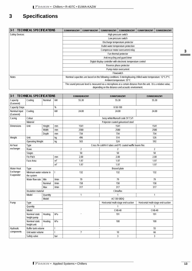
Safety Devices High pressure switchLow pressure switch
Discharge temperature protectorOutlet water temperature protectionCompressor motor overcurrent relay
Fan thermal protectorAnti-recycling and guard timer
Digital display controller with electronic temperature controlReverse phase protectorPump motor overcurrent
FlowswitchNotes Nominal capacities are based on the following conditions: Entering/leaving chilled water temperature: 12°C/7°C
Ambient temperature: 35°CThe sound pressure level is measured via a microphone at a certain distance from the unit. It is a relative value,
depending on the distance and acoustic environment.
3-1 TECHNICAL SPECIFICATIONS EUWAN24KAZW1 EUWAP24KAZW1 EUWAB24KAZW1
Capacity (Eurovent)
Cooling Nominal kW 55.30 55.30 55.30
Capacity Steps % 0-50-100Nominal input (Eurovent)
Cooling kW 24.00 24.00 24.00
Casing Colour Ivory white/Munsell code 5Y7.5/1Material Polyester coated galvanised steel
Dimensions Unit Height mm 1541 1541 1541Width mm 2580 2580 2580Depth mm 734 734 734
Weight Unit kg 496 514 526Operating Weight kg 503 524 592
Air heat exchanger
Type Cross fin coil/Hi-X tubes and PE coated waffle louvre finsRows 2 2 2Stages 50 50 50Fin Pitch mm 2.00 2.00 2.00Face Area m² 1.97 1.97 1.97
m² 1.97 1.97 1.97Water Heat Exchanger Evaporator
Type Brased plateMinimum water volume in the system
l 132 132 132
Water flow rate Min l/min 79 79 79Nominal l/min 158 158 158Max l/min 317 317 317
Insulation material ClimaflexModel Quantity 1 1 1
Model AC130-58DQPump Type
-
Horizontal multi-stage end-suction Horizontal multi-stage end-suctionQuantity 1 1Model CH8-40 CH8-40Nominal static height pump
Heating kPa 191 191
Nominal static height unit
Heating kPa 100 100
Hydraulic components
Buffer tank volume l - 55Unit water volume l 7 10 66Safety valve bar 3 3
3-1 TECHNICAL SPECIFICATIONS EUWAN16KAZW1 EUWAP16KAZW1 EUWAB16KAZW1 EUWAN20KAZW1 EUWAP20KAZW1 EUWAB20KAZW1
• Chillers • R-407C • EUWA-KAZW
• Applied Systems • Chillers14
3 Specifications
13
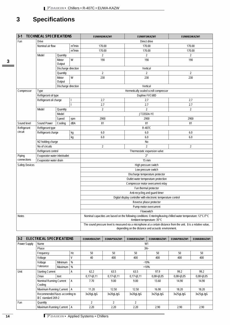
Fan Drive Direct driveNominal air flow m³/min 170.00 170.00 170.00
m³/min 170.00 170.00 170.00Model Quantity 2 2 2
Motor Output
W 190 190 190
Discharge direction VerticalQuantity 2 2 2Motor Output
W 230 230 230
Discharge direction VerticalCompressor Type Hermetically sealed scroll compressor
Refrigerant oil type Daphne FVC68DRefrigerant oil charge l 2.7 2.7 2.7
l 2.7 2.7 2.7Model Quantity 2 2 2
Model JT335DA-YESpeed rpm 2900 2900 2900
Sound level Sound Power Cooling dBA 81 81 81Refrigerant circuit
Refrigerant type R-407CRefrigerant charge kg 6.0 6.0 6.0
kg 6.0 6.0 6.0N2 holding charge NoNo of circuits 2 2 2Refrigerant control Thermostatic expansion valve
Piping connections
Evaporator water inlet/outlet 2’’Evaporator water drain 15 mm
Safety Devices High pressure switchLow pressure switch
Discharge temperature protectorOutlet water temperature protectionCompressor motor overcurrent relay
Fan thermal protectorAnti-recycling and guard timer
Digital display controller with electronic temperature controlReverse phase protectorPump motor overcurrent
FlowswitchNotes Nominal capacities are based on the following conditions: Entering/leaving chilled water temperature: 12°C/7°C
Ambient temperature: 35°CThe sound pressure level is measured via a microphone at a certain distance from the unit. It is a relative value,
depending on the distance and acoustic environment.
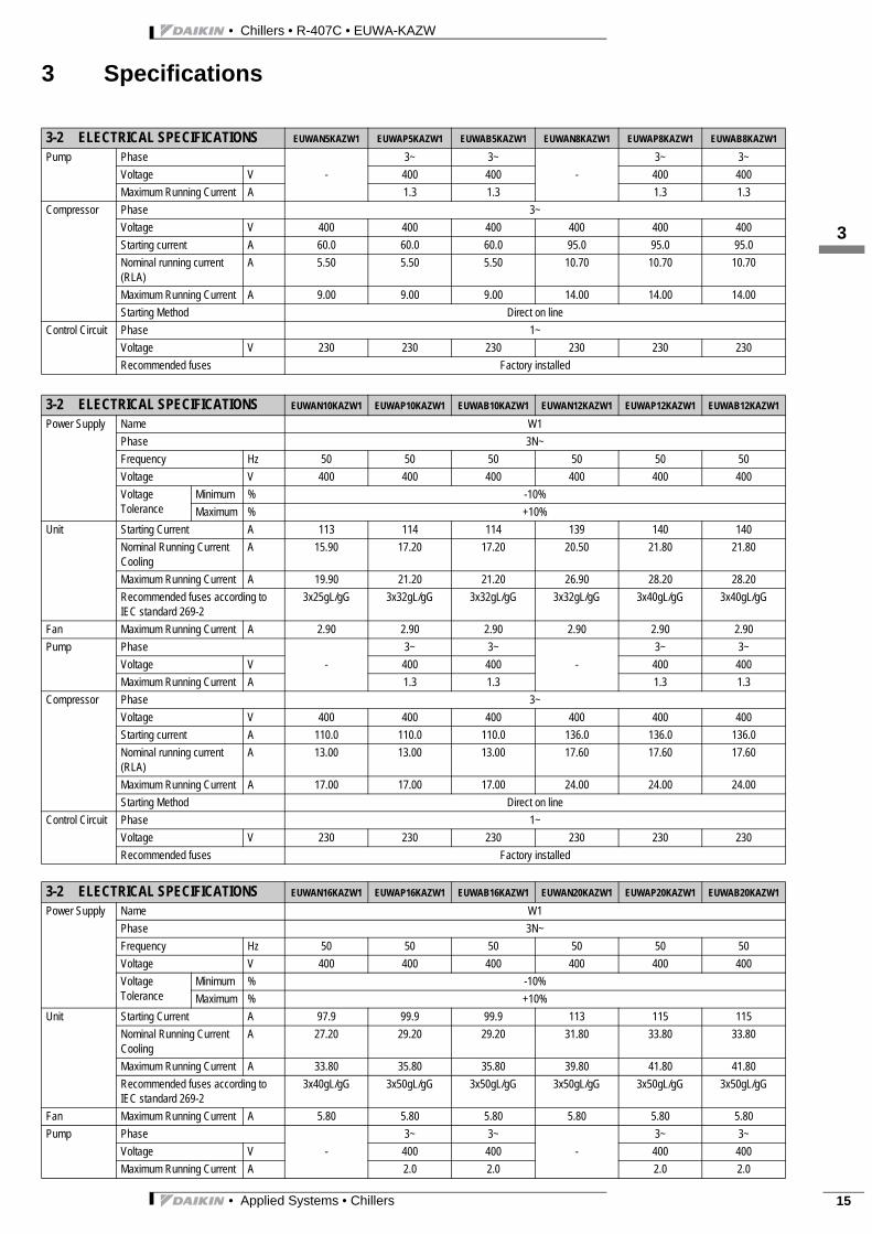
3-2 ELECTRICAL SPECIFICATIONS EUWAN5KAZW1 EUWAP5KAZW1 EUWAB5KAZW1 EUWAN8KAZW1 EUWAP8KAZW1 EUWAB8KAZW1
Power Supply Name W1Phase 3N~Frequency Hz 50 50 50 50 50 50Voltage V 40 400 400 400 400 400Voltage Tolerance
Minimum % -10%Maximum % +10%
Unit Starting Current A 62.2 63.5 63.5 97.9 99.2 99.2Zmax text 0,17+j0,11 0,17+j0,11 0,17+j0,11 0,08+j0,05 0,08+j0,05 0,08+j0,05Nominal Running Current Cooling
A 7.70 9.00 9.00 13.60 14.90 14.90
Maximum Running Current A 11.20 12.50 12.50 16.90 18.20 18.20Recommended fuses according to IEC standard 269-2
3x20gL/gG 3x20gL/gG 3x20gL/gG 3x25gL/gG 3x25gL/gG 3x25gL/gG
Fan Quantity 2 2 2Maximum Running Current A 2.20 2.20 2.20 2.90 2.90 2.90
3-1 TECHNICAL SPECIFICATIONS EUWAN24KAZW1 EUWAP24KAZW1 EUWAB24KAZW1
• Applied Systems • Chillers 15
• Chillers • R-407C • EUWA-KAZW
3 Specifications
3
13
Pump Phase-
3~ 3~-
3~ 3~Voltage V 400 400 400 400Maximum Running Current A 1.3 1.3 1.3 1.3
Compressor Phase 3~Voltage V 400 400 400 400 400 400Starting current A 60.0 60.0 60.0 95.0 95.0 95.0Nominal running current (RLA)
A 5.50 5.50 5.50 10.70 10.70 10.70
Maximum Running Current A 9.00 9.00 9.00 14.00 14.00 14.00Starting Method Direct on line
Control Circuit Phase 1~Voltage V 230 230 230 230 230 230Recommended fuses Factory installed
3-2 ELECTRICAL SPECIFICATIONS EUWAN10KAZW1 EUWAP10KAZW1 EUWAB10KAZW1 EUWAN12KAZW1 EUWAP12KAZW1 EUWAB12KAZW1
Power Supply Name W1Phase 3N~Frequency Hz 50 50 50 50 50 50Voltage V 400 400 400 400 400 400Voltage Tolerance
Minimum % -10%Maximum % +10%
Unit Starting Current A 113 114 114 139 140 140Nominal Running Current Cooling
A 15.90 17.20 17.20 20.50 21.80 21.80
Maximum Running Current A 19.90 21.20 21.20 26.90 28.20 28.20Recommended fuses according to IEC standard 269-2
3x25gL/gG 3x32gL/gG 3x32gL/gG 3x32gL/gG 3x40gL/gG 3x40gL/gG
Fan Maximum Running Current A 2.90 2.90 2.90 2.90 2.90 2.90Pump Phase
-3~ 3~
-3~ 3~
Voltage V 400 400 400 400Maximum Running Current A 1.3 1.3 1.3 1.3
Compressor Phase 3~Voltage V 400 400 400 400 400 400Starting current A 110.0 110.0 110.0 136.0 136.0 136.0Nominal running current (RLA)
A 13.00 13.00 13.00 17.60 17.60 17.60
Maximum Running Current A 17.00 17.00 17.00 24.00 24.00 24.00Starting Method Direct on line
Control Circuit Phase 1~Voltage V 230 230 230 230 230 230Recommended fuses Factory installed
3-2 ELECTRICAL SPECIFICATIONS EUWAN16KAZW1 EUWAP16KAZW1 EUWAB16KAZW1 EUWAN20KAZW1 EUWAP20KAZW1 EUWAB20KAZW1
Power Supply Name W1Phase 3N~Frequency Hz 50 50 50 50 50 50Voltage V 400 400 400 400 400 400Voltage Tolerance
Minimum % -10%Maximum % +10%
Unit Starting Current A 97.9 99.9 99.9 113 115 115Nominal Running Current Cooling
A 27.20 29.20 29.20 31.80 33.80 33.80
Maximum Running Current A 33.80 35.80 35.80 39.80 41.80 41.80Recommended fuses according to IEC standard 269-2
3x40gL/gG 3x50gL/gG 3x50gL/gG 3x50gL/gG 3x50gL/gG 3x50gL/gG
Fan Maximum Running Current A 5.80 5.80 5.80 5.80 5.80 5.80Pump Phase
-3~ 3~
-3~ 3~
Voltage V 400 400 400 400Maximum Running Current A 2.0 2.0 2.0 2.0
3-2 ELECTRICAL SPECIFICATIONS EUWAN5KAZW1 EUWAP5KAZW1 EUWAB5KAZW1 EUWAN8KAZW1 EUWAP8KAZW1 EUWAB8KAZW1
• Chillers • R-407C • EUWA-KAZW
• Applied Systems • Chillers16
3 Specifications
13
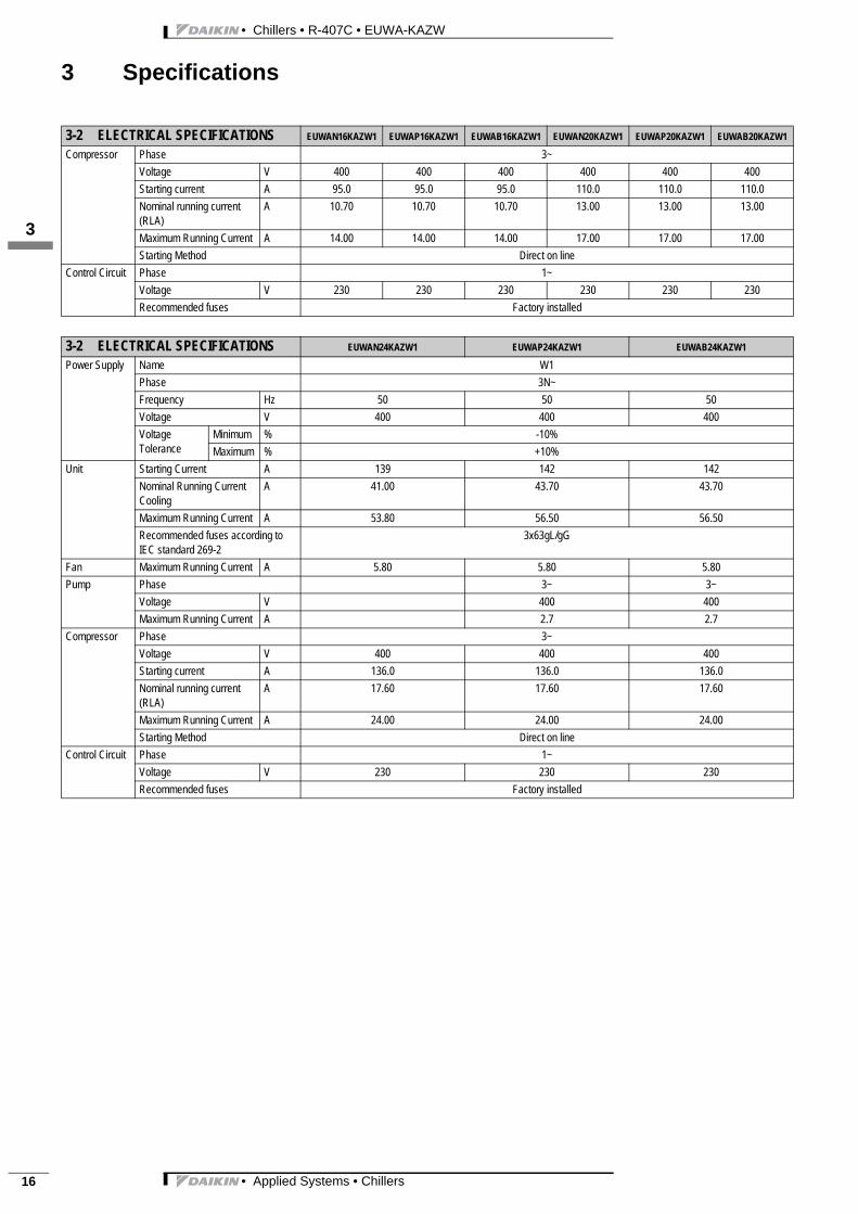
Compressor Phase 3~Voltage V 400 400 400 400 400 400Starting current A 95.0 95.0 95.0 110.0 110.0 110.0Nominal running current (RLA)
A 10.70 10.70 10.70 13.00 13.00 13.00
Maximum Running Current A 14.00 14.00 14.00 17.00 17.00 17.00Starting Method Direct on line
Control Circuit Phase 1~Voltage V 230 230 230 230 230 230Recommended fuses Factory installed
3-2 ELECTRICAL SPECIFICATIONS EUWAN24KAZW1 EUWAP24KAZW1 EUWAB24KAZW1
Power Supply Name W1Phase 3N~Frequency Hz 50 50 50Voltage V 400 400 400Voltage Tolerance
Minimum % -10%Maximum % +10%
Unit Starting Current A 139 142 142Nominal Running Current Cooling
A 41.00 43.70 43.70
Maximum Running Current A 53.80 56.50 56.50Recommended fuses according to IEC standard 269-2
3x63gL/gG
Fan Maximum Running Current A 5.80 5.80 5.80Pump Phase 3~ 3~
Voltage V 400 400Maximum Running Current A 2.7 2.7
Compressor Phase 3~Voltage V 400 400 400Starting current A 136.0 136.0 136.0Nominal running current (RLA)
A 17.60 17.60 17.60
Maximum Running Current A 24.00 24.00 24.00Starting Method Direct on line
Control Circuit Phase 1~Voltage V 230 230 230Recommended fuses Factory installed
3-2 ELECTRICAL SPECIFICATIONS EUWAN16KAZW1 EUWAP16KAZW1 EUWAB16KAZW1 EUWAN20KAZW1 EUWAP20KAZW1 EUWAB20KAZW1

• Applied Systems • Chillers 17
• Chillers • R-407C • EUWA-KAZW
4 Options
3
14
Num
ber
Desc
riptio
nDe
cimal
code
(On)
Unit
size
Avai
labi
lity
5KAZ
W8K
AZW
10KA
ZW12
KAZW
16KA
ZW20
KAZW
24KA
ZW
NP
BN
PB
NP
BN
PB
NP
BN
PB
NP
B
Stand
ardun
itVVVVVVVVVVVVVVVVVVVVV
Notc
ompl
etel
yco
mbi
nabl
eop
tions
1stdig
it
ZHchi
lledwa
tertem
pdow
nto-
5°C
12C-
-VVVVVVVVVVVVVVVVVVVVV
Factor
ymoun
ted
ZLchi
lledwa
tertem
pdow
nto-
10°C
24O-
-VVVVVVVVVVVVVVVVVVVVV
Factor
ymoun
ted
Com
plet
ely
com
bina
ble
optio
ns2n
d/3rd
digit
ESPFan
motor
sizeu
p(hig
hesp
5mmH
2O)
4--4
VVVVVVVVVVVVVVVVVVVVV
Factor
ymoun
ted
Optio
npum
phigh
Pump
sizeu
p8
--8-VV
-VV
-VV
-VV
-VV
-VV
-VV
Factor
ymoun
ted
OP10
Evapo
rator
heate
rtape
16--G
VVVVVVVVVVVVVVVVVVVVV
Factor
ymoun
ted
Avai
labl
eki
t
EKGA
U5/8K
Aga
uges
kit5/8
Hp-un
itsVVVVVV
--
--
--
--
--
--
--
-Kit
EKGA
U10/1
2KA
gaug
eskit
10/12
Hp-un
its-
--
--
-VVVVVV
--
--
--
--
-Kit
EKGA
U16K
Aga
uges
kit16
Hp-un
its-
--
--
--
--
--
-VVV
--
--
--
Kit
EKGA
U20/2
4KA
gaug
eskit
20/24
Hp-un
its-
--
--
--
--
--
--
--VVVVVV
Kit
EKSS
Softs
tarter
kitVVVVVVVVVVVV
--
--
--
--
-Kit
EKAC
10B(
Seen
otes2
)Ad
dress
card
VVVVVVVVVVVVVVVVVVVVV
Kit
EKBM
SMBA
(Seen
otes2
)ga
teway
forBM
S-M
odbu
sVVVVVVVVVVVVVVVVVVVVV
Kit
EKBM
SBNA
(Seen
otes2
)ga
teway
forBM
S-Ba
cnet
VVVVVVVVVVVVVVVVVVVVV
Kit
EKRU
MC(
Seen
otes2
)Re
mote
instal
leduse
rinter
face
VVVVVVVVVVVVVVVVVVVVV
Kit
EKBT
Buffe
rtank
200l
VVVVVVVVVVVVVVVVVVVVV
Kit
Exam
ple
ofpo
ssib
leop
tion
com
bina
tions
ESP+
Optio
npum
phigh
12--C
ESP+
OP10
20--K
ESP+
OP10
+Op
tionp
umph
igh28
--S
OP10
+Op
tionp
umph
igh24
--O
3TW
5562
9-5
NO
TES
1
VA
vaila
ble
-N
otav
aila
ble
V-
Ava
ilabl
ean
da
quan
tity
isne
cess
ary
/un
it
Impo
ssib
leop
tion
com
bina
tions
:ZH
+ZL
NO
TES
2To
inst
allE
KBM
SMBA
,EKB
MSB
NA
and
EKRU
MC=
>EK
AC1
0Bne
eds
tobe
inst
alle
don
the
unit.

• Chillers • R-407C • EUWA-KAZW
• Applied Systems • Chillers18
5 Control systems
15
Direct and user parameters
The digital controller provides direct and user parameters. The direct parameters are important for the everyday usage of the unit, e.g. toadjust the temperature setpoint or to consult actual operational information. The user parameters on the contrary provide advanced featuressuch as adjusting time delays or disabling the buzzer. Each parameter is defined by a code and a value. For example, the parameter used toselect local or remote on/off control has code h7 and value 1 or 0.
User interface EUWA5-24KAZW
The digital controller consists of a numeric display, four labelled keys which you can press an four LEDs providing extra user information.
Digital controller
Keys provided on the controller.
Each key, except for the lower left key, combines two functions:m / k,o / i and b / c. The functioncarried out when the user presses one of these keys depends onthe status of the controller and the unit at that specific moment.
m Key, to enter the scroll list of user parameters, to confirma parameter modification and to return to normaloperation.
k Key, to de-activate the buzzer in the case of an alarm.
o Key, to scroll through the list of direct or user parametersor to raise a setting.
i Key, to start the unit in heating mode or to switch theunit off when heating mode is active.(only heatpump models)
n Key, to enter the scroll list of direct parameters or toswitch between a parameter’s code and its value.
b Key, to start the unit in cooling mode or to switch theunit off when cooling mode is active.
c Key, to scroll through the list of direct or user parametersor to lower a setting.
comp
x 100
clear
PRGmute
SEL
LEDs provided on the controller:
The controller provides five LEDs one of which, the left lLED, is not used.
l LED, indicates the status of the compressor.The LED does not light up when the compressor is notactive, blinks when the compressor cannot start upalthough extra load is requested (e.g. timer active) andlights up permanently when the compressor is active.
i LED, indicates that heating mode is active.(only heatpump models)
b LED, indicates that cooling mode is active.
s LED, indicates that the value on the numeric displayshould be multiplied by 100.
Note:
– Temperature readout tolerance: ±1°C.– Legibility of the numeric display may decrease in direct sunlight.
• Applied Systems • Chillers 19
• Chillers • R-407C • EUWA-KAZW
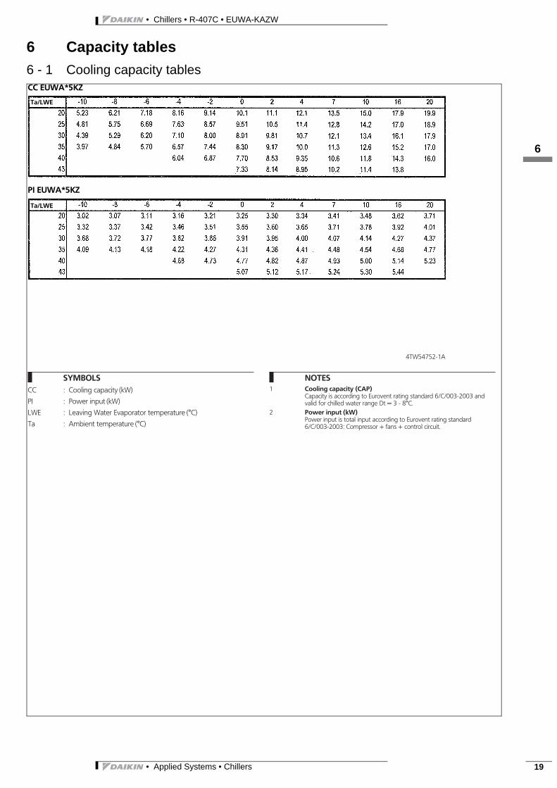
6 Capacity tables6 - 1 Cooling capacity tables
3
16
4TW54752-1A
SYMBOLSCC : Cooling capacity (kW)
PI : Power input (kW)
LWE : Leaving Water Evaporator temperature (°C)
Ta : Ambient temperature (°C)
NOTES1 Cooling capacity (CAP)
Capacity is according to Eurovent rating standard 6/C/003-2003 andvalid for chilled water range Dt = 3 - 8°C.
2 Power input (kW)Power input is total input according to Eurovent rating standard6/C/003-2003: Compressor + fans + control circuit.
CC EUWA*5KZ
Ta/LWE
PI EUWA*5KZ
Ta/LWE

• Chillers • R-407C • EUWA-KAZW
• Applied Systems • Chillers20
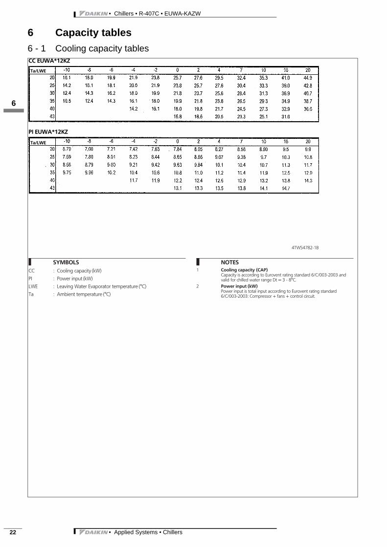
6 Capacity tables6 - 1 Cooling capacity tables
16
4TW54762-1A
SYMBOLSCC : Cooling capacity (kW)
PI : Power input (kW)
LWE : Leaving Water Evaporator temperature (°C)
Ta : Ambient temperature (°C)
NOTES1 Cooling capacity (CAP)
Capacity is according to Eurovent rating standard 6/C/003-2003 andvalid for chilled water range Dt = 3 - 8°C.
2 Power input (kW)Power input is total input according to Eurovent rating standard6/C/003-2003: Compressor + fans + control circuit.
CC EUWA*8KZ
Ta/LWE
PI EUWA*8KZ
Ta/LWE

• Applied Systems • Chillers 21
• Chillers • R-407C • EUWA-KAZW
6 Capacity tables6 - 1 Cooling capacity tables
3
16
4TW54772-1A
SYMBOLSCC : Cooling capacity (kW)
PI : Power input (kW)
LWE : Leaving Water Evaporator temperature (°C)
Ta : Ambient temperature (°C)
NOTES1 Cooling capacity (CAP)
Capacity is according to Eurovent rating standard 6/C/003-2003 andvalid for chilled water range Dt = 3 - 8°C.
2 Power input (kW)Power input is total input according to Eurovent rating standard6/C/003-2003: Compressor + fans + control circuit.
CC EUWA*10KZ
Ta/LWE
PI EUWA*10KZ
Ta/LWE
• Chillers • R-407C • EUWA-KAZW
• Applied Systems • Chillers22
6 Capacity tables6 - 1 Cooling capacity tables
16
4TW54782-1B
SYMBOLSCC : Cooling capacity (kW)
PI : Power input (kW)
LWE : Leaving Water Evaporator temperature (°C)
Ta : Ambient temperature (°C)
NOTES1 Cooling capacity (CAP)
Capacity is according to Eurovent rating standard 6/C/003-2003 andvalid for chilled water range Dt = 3 - 8°C.
2 Power input (kW)Power input is total input according to Eurovent rating standard6/C/003-2003: Compressor + fans + control circuit.
CC EUWA*12KZ
Ta/LWE
PI EUWA*12KZ
Ta/LWE

• Applied Systems • Chillers 23
• Chillers • R-407C • EUWA-KAZW
6 Capacity tables6 - 1 Cooling capacity tables
3
16
4TW54792-1A
SYMBOLSCC : Cooling capacity (kW)
PI : Power input (kW)
LWE : Leaving Water Evaporator temperature (°C)
Ta : Ambient temperature (°C)
NOTES1 Cooling capacity (CAP)
Capacity is according to Eurovent rating standard 6/C/003-2003 andvalid for chilled water range Dt = 3 - 8°C.
2 Power input (kW)Power input is total input according to Eurovent rating standard6/C/003-2003: Compressor + fans + control circuit.
CC EUWA*16KZ
Ta/LWE
PI EUWA*16KZ
Ta/LWE

• Chillers • R-407C • EUWA-KAZW
• Applied Systems • Chillers24
6 Capacity tables6 - 1 Cooling capacity tables
16
4TW54802-1A
SYMBOLSCC : Cooling capacity (kW)
PI : Power input (kW)
LWE : Leaving Water Evaporator temperature (°C)
Ta : Ambient temperature (°C)
NOTES1 Cooling capacity (CAP)
Capacity is according to Eurovent rating standard 6/C/003-2003 andvalid for chilled water range Dt = 3 - 8°C.
2 Power input (kW)Power input is total input according to Eurovent rating standard6/C/003-2003: Compressor + fans + control circuit.
CC EUWA*20KZ
Ta/LWE
PI EUWA*20KZ
Ta/LWE

• Applied Systems • Chillers 25
• Chillers • R-407C • EUWA-KAZW
6 Capacity tables6 - 1 Cooling capacity tables
3
16
4TW54812-1A
SYMBOLSCC : Cooling capacity (kW)
PI : Power input (kW)
LWE : Leaving Water Evaporator temperature (°C)
Ta : Ambient temperature (°C)
NOTES1 Cooling capacity (CAP)
Capacity is according to Eurovent rating standard 6/C/003-2003 andvalid for chilled water range Dt = 3 - 8°C.
2 Power input (kW)Power input is total input according to Eurovent rating standard6/C/003-2003: Compressor + fans + control circuit.
CC EUWA*24KZ
Ta/LWE
PI EUWA*24KZ
Ta/LWE

• Chillers • R-407C • EUWA-KAZW
• Applied Systems • Chillers26
6 Capacity tables6 - 2 Capacity correction factor
16
4TW54179-1
CORRECTION FACTOR FOR GLYCOL
Ethylene glycolPropylene glycol
Legend:
Kc Correction on cooling capacityKi Correction on power inputKf Correction on flow rateKp Correction on pressure drop
Glycol
Required glycol concentration
Type Concentration (wt%) 0 10 20 30 40
Ethylene glycolFreezing point °C 0 -4 -9 -16 -23Minimum LWE °C 5 2 0 -5 -11
Propylene glycolFreezing point °C 0 -3 -7 -13 -22Minimum LWE °C 5 3 -2 -4 -10

• Applied Systems • Chillers 27
• Chillers • R-407C • EUWA-KAZW
7 Dimensional drawing & centre of gravity7 - 1 Dimensional drawing
3
17
3TW55694-1
EUWAN5-8KAZW
1 Air heat exchanger2 Compressor3 Switch box4 Main switch5 Digital display controller6 Water heat exchanger7 Water IN connection: 1 1/4’’ M BSP8 Water OUT connection: 1 1/4’’ M BSP9 Power supply intake
10 Drain11 Air purge12 Pressure port13 Ball valve: 1-1/4’’ BSP14 Water filter: 1-1/4’’ BSP15 Flow switch16 High pressure gauge (optional)17 Low pressure gauge (optional)18 4 way valve *19 Accumulator *20 Liquid receiver *
* Only for H/P models
Free space B1/B2
Free space min. 3 m
FIXATION 4XJ15
Caution for fan Caution for fan
SERVICE SPACE Filte
rkit
Filterkit (delivered with the unit)
3TW55694-2
EUWAP5-8KAZW
1 Air heat exchanger2 Compressor3 Switch box4 Main switch5 Pump switch6 Digital display controller7 Water heat exchanger8 Water IN connection: 1 1/4’’ M BSP9 Water OUT connection: 1 1/4’’ M BSP
10 Power supply intake11 Drain12 Air purge13 Expansion vessel14 Safety valve15 Manometer (water)16 Pressure port17 Ball valve: 1-1/4’’ BSP18 Water filter: 1-1/4’’ BSP19 Pump20 Regulation valve21 Flow switch22 High pressure gauge (optional)23 Low pressure gauge (optional)24 Pump drain25 4 way valve *26 Accumulator *27 Liquid receiver *
* Only for H/P models
Free space B1/B2
Free space min. 3 m
FIXATION 4XJ15
Caution for fan Caution for fan
SERVICE SPACE Filte
rkit
Filterkit (delivered with the unit)
• Chillers • R-407C • EUWA-KAZW
• Applied Systems • Chillers28
7 Dimensional drawing & centre of gravity7 - 1 Dimensional drawing
17
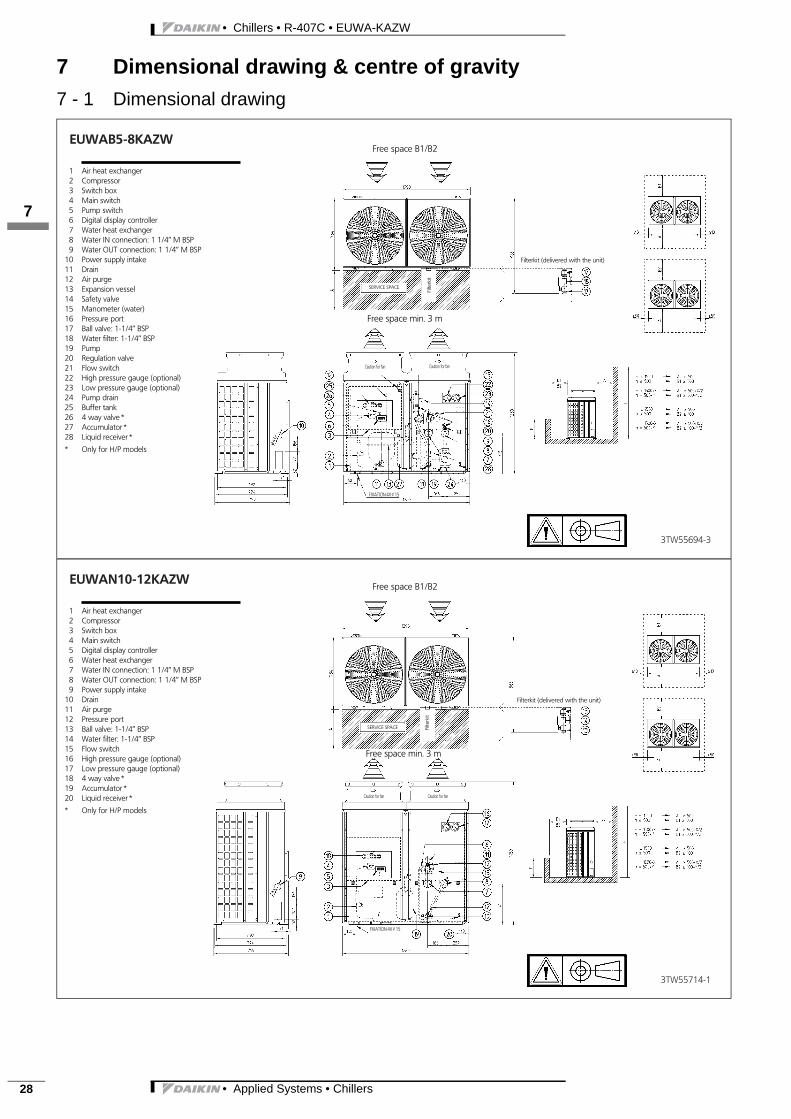
3TW55694-3
EUWAB5-8KAZW
1 Air heat exchanger2 Compressor3 Switch box4 Main switch5 Pump switch6 Digital display controller7 Water heat exchanger8 Water IN connection: 1 1/4’’ M BSP9 Water OUT connection: 1 1/4’’ M BSP
10 Power supply intake11 Drain12 Air purge13 Expansion vessel14 Safety valve15 Manometer (water)16 Pressure port17 Ball valve: 1-1/4’’ BSP18 Water filter: 1-1/4’’ BSP19 Pump20 Regulation valve21 Flow switch22 High pressure gauge (optional)23 Low pressure gauge (optional)24 Pump drain25 Buffer tank26 4 way valve *27 Accumulator *28 Liquid receiver *
* Only for H/P models
Free space B1/B2
Free space min. 3 m
FIXATION 4XJ15
Caution for fan Caution for fan
SERVICE SPACE
Filte
rkit
Filterkit (delivered with the unit)
3TW55714-1
EUWAN10-12KAZW
1 Air heat exchanger2 Compressor3 Switch box4 Main switch5 Digital display controller6 Water heat exchanger7 Water IN connection: 1 1/4’’ M BSP8 Water OUT connection: 1 1/4’’ M BSP9 Power supply intake
10 Drain11 Air purge12 Pressure port13 Ball valve: 1-1/4’’ BSP14 Water filter: 1-1/4’’ BSP15 Flow switch16 High pressure gauge (optional)17 Low pressure gauge (optional)18 4 way valve *19 Accumulator *20 Liquid receiver *
* Only for H/P models
Free space B1/B2
Free space min. 3 m
FIXATION 4XJ15
Caution for fan Caution for fan
SERVICE SPACE Filte
rkit
Filterkit (delivered with the unit)

• Applied Systems • Chillers 29
• Chillers • R-407C • EUWA-KAZW
7 Dimensional drawing & centre of gravity7 - 1 Dimensional drawing
3
17
3TW55714-2
EUWAP10-12KAZW
1 Air heat exchanger2 Compressor3 Switch box4 Main switch5 Pump switch6 Digital display controller7 Water heat exchanger8 Water IN connection: 1 1/4’’ M BSP9 Water OUT connection: 1 1/4’’ M BSP
10 Power supply intake11 Drain12 Air purge13 Expansion vessel14 Safety valve15 Manometer (water)16 Pressure port17 Ball valve: 1-1/4’’ BSP18 Water filter: 1-1/4’’ BSP19 Pump20 Regulation valve21 Flow switch22 High pressure gauge (optional)23 Low pressure gauge (optional)24 Pump drain25 4 way valve *26 Accumulator *27 Liquid receiver *
* Only for H/P models
Free space B1/B2
Free space min. 3 m
FIXATION 4XJ15
Caution for fan Caution for fan
SERVICE SPACE
Filte
rkit
Filterkit (delivered with the unit)
3TW55714-3
EUWAB10-12KAZW
1 Air heat exchanger2 Compressor3 Switch box4 Main switch5 Pump switch6 Digital display controller7 Water heat exchanger8 Water IN connection: 1 1/4’’ M BSP9 Water OUT connection: 1 1/4’’ M BSP
10 Power supply intake11 Drain12 Air purge13 Expansion vessel14 Safety valve15 Manometer (water)16 Pressure port17 Ball valve: 1-1/4’’ BSP18 Water filter: 1-1/4’’ BSP19 Pump20 Regulation valve21 Flow switch22 High pressure gauge (optional)23 Low pressure gauge (optional)24 Pump drain25 Buffer tank26 4 way valve *27 Accumulator *28 Liquid receiver *
* Only for H/P models
Free space B1/B2
Free space min. 3 m
FIXATION 4XJ15
Caution for fan Caution for fan
SERVICE SPACE Filte
rkit
Filterkit (delivered with the unit)

• Chillers • R-407C • EUWA-KAZW
• Applied Systems • Chillers30
7 Dimensional drawing & centre of gravity7 - 1 Dimensional drawing
17
3TW55734-1
EUWAN16KAZW
1 Air heat exchanger2 Compressor3 Switch box4 Main switch5 Digital display controller6 Water heat exchanger7 Water IN connection: 2’’ M BSP8 Water OUT connection: 2’’ M BSP9 Power supply intake
10 Drain11 Air purge12 Pressure port13 Ball valve14 Water filter15 Flow switch16 High pressure gauge (optional)17 Low pressure gauge (optional)18 4 way valve *19 Accumulator *20 Liquid receiver *
* Only for H/P models
Free space B1/B2
Free space min. 3 m
FIXATION 4XJ15
Caution for fan Caution for fan
SERVICE SPACE
Filte
rkit
Caution for fan Caution for fan
Filterkit (delivered with the unit)
3TW55734-2
EUWAP16KAZW
1 Air heat exchanger2 Compressor3 Switch box4 Main switch5 Pump switch6 Digital display controller7 Water heat exchanger8 Water IN connection: 2’’ M BSP9 Water OUT connection: 2’’ M BSP
10 Power supply intake11 Drain12 Air purge13 Expansion vessel14 Safety valve15 Pressure port16 Ball valve17 Water filter18 Pump19 Regulation valve20 Flow switch21 High pressure gauge (optional)22 Low pressure gauge (optional)23 Pump drain24 Water pressure gauge25 4 way valve *26 Accumulator *27 Liquid receiver *
* Only for H/P models
Free space B1/B2
Free space min. 3 m
FIXATION 4XJ15
Caution for fan Caution for fan
SERVICE SPACE
Filte
rkit
Caution for fan Caution for fan
Filterkit (delivered with the unit)

• Applied Systems • Chillers 31
• Chillers • R-407C • EUWA-KAZW
7 Dimensional drawing & centre of gravity7 - 1 Dimensional drawing
3
17
3TW55734-3
EUWAB16KAZW
1 Air heat exchanger2 Compressor3 Switch box4 Main switch5 Pump switch6 Digital display controller7 Water heat exchanger8 Water IN connection: 2’’ M BSP9 Water OUT connection: 2’’ M BSP
10 Power supply intake11 Drain12 Air purge13 Expansion vessel14 Safety valve15 Pressure port16 Ball valve17 Water filter18 Pump19 Regulation valve20 Flow switch21 High pressure gauge (optional)22 Low pressure gauge (optional)23 Pump drain24 Water pressure gauge25 4 way valve *26 Accumulator *27 Liquid receiver *28 Buffer tank
* Only for H/P models
Free space B1/B2
Free space min. 3 m
FIXATION 4XJ15
Caution for fan Caution for fan
SERVICE SPACE
Filte
rkit
Caution for fan Caution for fan
Filterkit (delivered with the unit)
3TW55744-1
EUWAN20-24KAZW
1 Air heat exchanger2 Compressor3 Switch box4 Main switch5 Digital display controller6 Water heat exchanger7 Water IN connection: 2’’ M BSP8 Water OUT connection: 2’’ M BSP9 Power supply intake
10 Drain11 Air purge12 Pressure port13 Ball valve14 Water filter15 Flow switch16 High pressure gauge (optional)17 Low pressure gauge (optional)18 4 way valve *19 Accumulator *20 Liquid receiver *
* Only for H/P models
Free space B1/B2
Free space min. 3 m
FIXATION 4XJ15
Caution for fan Caution for fan
SERVICE SPACE
Filte
rkit
Caution for fan Caution for fan
Filterkit (delivered with the unit)

• Chillers • R-407C • EUWA-KAZW
• Applied Systems • Chillers32
7 Dimensional drawing & centre of gravity7 - 1 Dimensional drawing
17
3TW55744-2
EUWAP20-24KAZW
1 Air heat exchanger2 Compressor3 Switch box4 Main switch5 Pump switch6 Digital display controller7 Water heat exchanger8 Water IN connection: 2’’ M BSP9 Water OUT connection: 2’’ M BSP
10 Power supply intake11 Drain12 Air purge13 Expansion vessel14 Safety valve15 Pressure port16 Ball valve17 Water filter18 Pump19 Regulation valve20 Flow switch21 High pressure gauge (optional)22 Low pressure gauge (optional)23 Pump drain24 Water pressure gauge25 4 way valve *26 Accumulator *27 Liquid receiver *
* Only for H/P models
Free space B1/B2
Free space min. 3 m
FIXATION 4XJ15
Caution for fan Caution for fan
SERVICE SPACEFi
lterk
it
Caution for fan Caution for fan
Filterkit (delivered with the unit)
3TW55744-3
EUWAB20-24KAZW
1 Air heat exchanger2 Compressor3 Switch box4 Main switch5 Pump switch6 Digital display controller7 Water heat exchanger8 Water IN connection: 2’’ M BSP9 Water OUT connection: 2’’ M BSP
10 Power supply intake11 Drain12 Air purge13 Expansion vessel14 Safety valve15 Pressure port16 Ball valve17 Water filter18 Pump19 Regulation valve20 Flow switch21 High pressure gauge (optional)22 Low pressure gauge (optional)23 Pump drain24 Water pressure gauge25 4 way valve *26 Accumulator *27 Liquid receiver *28 Buffer tank
* Only for H/P models
Free space B1/B2
Free space min. 3 m
FIXATION 4XJ15
Caution for fan Caution for fan
SERVICE SPACE
Filte
rkit
Caution for fan Caution for fan
Filterkit (delivered with the unit)

• Applied Systems • Chillers 33
• Chillers • R-407C • EUWA-KAZW
7 Dimensional drawing & centre of gravity7 - 2 Centre of gravity
3
17
4TW54759-2
EUWA*5-12KAZW
5Hp 8Hp 10Hp 12HpA B A B A B A B
B-Models 520 420 480 420 490 430 490 430P-Models 510 420 470 420 480 430 490 430N-Models 480 420 440 430 450 430 460 430

• Chillers • R-407C • EUWA-KAZW
• Applied Systems • Chillers34
7 Dimensional drawing & centre of gravity7 - 2 Centre of gravity
17
4TW54799-2
EUWA*16-24KAZW
16Hp 20Hp 24HpA B A B A B
B-Models 1115 435 1120 435 1115 435P-Models 1145 435 1140 435 1135 435N-Models 1110 430 1115 435 1110 435

• Applied Systems • Chillers 35
• Chillers • R-407C • EUWA-KAZW
8 Piping diagram
3
18
3TW55625-1
EUWA*5-24KAZW
O Check valve L Flare connection M Screw connection N Flange connection Z Pinched pipe P Spinned pipe
Expansion valve
Air purge
Pressureregulating
valve
N-Models
R3T Inlet water temperature sensorR4T Outlet water temperature sensorR5T Ambient temperature sensorS*HP High pressure switchS*LP Low pressure switchM*F Condenser fanM*C Compressor
Condenser
B-Models
Filter
Servicevalve
Low pressureservice port
Service valve
COOLING
Buffer tank
Pump
Pressure gauges
Expansion vessel
Water sideEUWA 5-8-10-12: 1xEUWA 16-20-24: 2x
Refrigerant side
Water inlet
P/B-Models
Water outlet
Evaporator
Refrigerant side
Drainvalve
Drainvalve
N/P-Models
Drainvalve
Expansion vessel
Safety valve
Water side
Air purge
Serviceport
Drain
Shut off valve
Service port
P-Models
Filter
Shut off valve
Flowswitch
Serviceport
Safetyvalve
Service port
Service port
Overview
P/B-Models N/P-Models
Field installation

• Chillers • R-407C • EUWA-KAZW
• Applied Systems • Chillers36
9 Wiring diagram9 - 1 Wiring diagram
19
1TW55626-1C
NOTES
(1) Terminal 1
(2) Wire 2
(3) F Field wiring, to be in accordance with the localelectrical regulations
(4) C Earth wiring
(5) Option
(6) PCB
(7) Outside switchbox
(8) If compressor rotates reversely, it may be damaged.
(9) WC: Water chillerRC: Unit with remote condensor
(10)OPTIONALM OP10 = Evaporator heatertapeM AKAC108 = Address card kit for BMS-connectionsM EKSS = Soft starterM OP pump high= High head pressure pumpM EKRUMC = Remote user interface
FusesFor units with integrated pump (400V)
5HP 8HP 10HP 12HP 16HP 20HP 24HPF1,F2,F3 (=gl.GG) 3x20A 3x25A 3x32A 3x40A 3x50A 3x50A 3x63A
FusesFor units without integrated pump (400V)
5HP 8HP 10HP 12HP 16HP 20HP 24HPF1,F2,F3 (=gl.GG) 3x20A 3x25A 3x25A 3x32A 3x40A 3x50A 3x63A
Fuses + overcurrentAll models (400V)
5HP 8HP 10HP 12HP 16HP 20HP 24HPF4 8A 8A 8A 8A 8A 8A 8AF5 125mAT 125mAT 125mAT 125mAT 125mAT 125mAT 125mATF7,F8 5A 5A 5A 5A 5A 5A 5AF1U 5A 5A 5A 5A 5A 5A 5AF3U 315mAT 315mAT 315mAT 315mAT 315mAT 315mAT 315mATK4S 9A 14A 17A 24A 14A 17A 24AK5S - - - - 14A 17A 24AK6S(St. Pump) 1.3A 1.3A 1.3A A.3A 2A 2A 2.7AK6S(OP pump high) 2.5A 2.5A 2.5A 2.5A 3.8A 3.8A 3.8AK6S(OP ZH/ZL) 2.9A 2.9A 2.9A 2.9A 2.9A 2.9A 4AK6S(OP pump high+ OP ZH/ZL) 2.5A 2.5A 2.5A 2.5A 5.2A 5.2A 5.2A
For AC16-24
Option kit EKAC108
To microchiller compact
0 1 2 3 4 5 6 7 8 9 10 11
For AC16-
For AC5-12ForAC5-12
Address cards
Serial line togateway
Defrost temp. Unit
Only forAC16-24
Only for AC16-24
(11) Terminals for fieldwiring
X1M: H3-6P, Y3R, K1-2F: Output term(voltage free contact max 2A/ou
X2M: ESH: Fieldheater (max 500W resX3M: S7S, S9S: Input terminal for field
(switch load 6mA / 30VDCY1R, Y2R are activated in cooling mod
(12) Y3R Is activated in cooling modeS7S Open = HeatingS7S Closed = Cooling
(13) Dipswitch: Unit setting
S2A dipswitch: Defrost & fan setting
1>only applicable for heatpumpOff = start condition 1 for defrost cycleOn = start condition 2 for defrost cycle (
2>Off = fansetting 1 (5, 8, 16HP)On = fansetting 2 (10, 12, 20, 24HP)
Remote userinterface
Only for 5-24 Heat pump
Option kit EKRUMC
Only for 16-24 Heat pump
Only for 16-24
to cableshield
For AC8-24
For AC5
For AC16-24
• Applied Systems • Chillers 37
• Chillers • R-407C • EUWA-KAZW
9 Wiring diagram9 - 1 Wiring diagram
3
19
12 13 14 15 16 17 18 19 20
6-24
12
Only for
Only for 16-24HP
Defrost temp. Unit
S1A Dipswitch: Unit setting1 > Off= 1 circuit
On= 2 circuit234 > Off Off Off = WC CO & WC cL CO
Off On Off = AC COOn Off Off = AC HP (without compr. stop for defrost cycle)On Off On = AC HP (with compr. stop for defrost cycle)
minal for field wiringoutput)esistive / 230Vac / 50hz)d wiring (don’t connect voltage)
ode
ee (5, 8, 10, 12, 16, 20, 24HP)
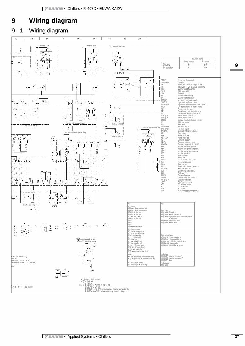
A2P A1PDigital inputsDl1 Reverse phase detection (L1-N)Dl2 Reverse phase detection (N-L3)Dl3 M1C ON detectionDl4 M2C ON detectionDl5 Safety device detectionDl6 Pump ON detectionDl7 --Dl8 --Dl9 --Dl10 Reverse valve request
Digital inputsX1 (lD1-GND): Flow switchX1 (lD2-GND): Remote C/H selectionX1 (lD3-GND): High pressure switch + discharge protector
+ overcurrentX1 (lD4-GND): Low pressure switchX1 (lD5-GND): Remote On/Off
Digital outputs (Relays)RY1 Reversed phase protectorRY3 Pump / general operationRY4-24 Fan speed relay 1RY5-25 Fan speed relay 2RY6 HeatertapeRY7 Reversing valve circ1RY8 Reversing valve circ2RY9 M1C Off (during defrost)RY10 M2C Off (during defrost)RY12-22 Fan speed relayRY27 Reversing valve of water circuit
Digital outputs (Relays)X2 (C1/2-N01): Compressor M1C onX2 (C1/2-N02): Compressor M2C onX2 (C3/4-N03): Voltage free contact for pumpX2 (C3/4-N04): Reversing valveX2 (C5-N05): Alarm voltage free contact
OthersHAP Light emitting diode (service monitor green)H1P,H2P Light emitting diode (service monitor red)
S1A Dipswitch (unit setting)S2A Dipswitch (defr. & fan settting)
Analog inputsX1 (B1-GND): Evaporator inlet water t°X1 (B2-GND): Evaporator outlet water t°X1 (B3-GND): NoneAnalog outputX1 (Y-GND)
Not standard includedNot poss. as option Poss. as option
Obligatory # ##Not obligatory ∗ ∗∗
Y1R, Y2R Reverse valve of water circuitX1-82(A/B/M) ConnectorsTR2 Transfo 230V → 24V for supply of I/O PCBTR1 Transfo 230V → 24V for supply of controller PCBS21P Switch for pump Manual/AutoS12M Main isolator switchS10L FlowswitchS9S * Switch for remote start/stopS7S * Switch for cool/heat selectionS4LP,S5LP Low pressure switch circuit 1, circuit 2S1HP,S2HP High pressure switch circuit 1, circuit 2S21HP, S22HP high pressure switch during defrost circuit 1, circuit 2R7T, R9T Coil temperature sensor for circuit 1, circuit 2R6T Ambient temperature sensorR4T Evaporator outlet water temperature sensorR3T Evaporator inlet water temperature sensorQ21F, Q22F Thermal protector fan circuit 2Q11F, Q12F Thermal protector fan circuit 1Q1D,Q2D Discharge thermal protector circuit 1, circuit 2PE Main earth terminalM1P Pump motorM11F, M12F Fan motors circuit 1M21F, M22F Fan motors circuit 2M1C,M2C Compressor motor circuit 1, circuit 2K1P * Pump contactorK1A Auxiliary bypass relayK21A, K22A Auxiliary bypass relayK6S * Overcurrent relay pumpK4S,K5S Overcurrent relay circuit 1, circuit 2K1M,K2M Compressor contactor circuit 1, circuit 2H6P * Indication lamp general operationH5P * Indication lamp operation compressor 2H4P * Indication lamp operation compressor 1H3P * Indication lamp alarmF3U Fuse controller PCBF1U Fuse I/O PCBF7, F8 Fuse for fan motor circuit 1, circuit 2F6 # Fuse for pump contactorF5 ## Surge proof fuseF4 Fuse I/O PCB & Evaporator heatertapeF1,F2,F3 # Main fuses for the unitE6H Buffertank (55l) option KIS111Z7E5H Field heaterE3H, E4H Evaporator heatertapeE1H,E2H Crankcase heater circuit 1, circuit 2C1, C2, C3, C4 Capacitors for fanmotorsA7P ** PCB: Remote user interfaceA5P PCB: softstarter for circuit 1A3P ** PCB: address cardA2P PCB: I/O PCBA1P PCB: Discharge pipe (spinning end)PCB
(13) Pump contact for unitswithout integrated pump
Only for
For heating only For heating onlyOnly for heatpump
Only forAC16-24 Heat pump
Only for AC16-24
Only for AC5-24
For units with integrated pump
For units without integrated pump
Only for Heat pump

• Chillers • R-407C • EUWA-KAZW
• Applied Systems • Chillers38
10 Sound data10 - 1 Sound power spectrum
110
Sound power Lw per Octave band (dB) Total(dBA)
63 125 250 500 1000 2000 4000 8000 LwAEUWA/Y(*)5K(A)ZW1 70 71 67 64 61 59 53 46 67EUWA/Y(*)8K(A)ZW1 78 76 72 77 68 64 58 52 76EUWA/Y(*)10K(A)ZW1 82 91 77 77 71 67 63 57 78EUWA/Y(*)12K(A)ZW1 82 91 77 77 71 67 63 57 78EUWA/Y(*)16K(A)ZW1 81 79 75 80 71 67 61 55 79EUWA/Y(*)20K(A)ZW1 85 94 80 80 74 70 66 60 81EUWA/Y(*)24K(A)ZW1 85 94 80 80 74 70 66 60 81
4TW54757-1D
NOTES
1. Data valid at nominal operation condition2. Measured according ISO3744

• Applied Systems • Chillers 39
• Chillers • R-407C • EUWA-KAZW
11 Installation11 - 1 Water charge, flow and quality
3
111
Be sure the water quality is in accordance with the specifications below:
ITEMS Cooled water Tendency if out ofcriteriaCirculating water
(below 20°C)Water supply
Items to be controlled:- pH at 25°C 6.8 - 8.0 6.8 - 8.0 Corrosion + scale
- Electrical conduct(mS/m) at 25°C Below 40 Below 30 Corrosion + scale
(μS/cm) at 25°C ⎯ ⎯ Corrosion + scale
- Chloride ion (mg Cl-/l) Below 50 Below 50 Corrosion
- Sulfate ion (mg SO 24-/l) Below 50 Below 50 Corrosion
- M-alkalinity (pH 4.8) (mg SO3/l) Below 50 Below 50 Scale
- Total hardness (mg CaCO3/l) Below 70 Below 70 Scale
- Calcium hardness (mg CaCO3/l) Below 50 Below 50 Scale
- Silica ion (mg SiO2/l) Below 30 Below 30 Scale
Items to be referred to:
- Iron (mg Fe/l) Below 1.0 Below 0.3 Corrosion + scale
- Copper (mg Cu/l) Below 1.0 Below 0.1 Corrosion
- Sulfite ion (mg S 2-/l) Not detectable Not detectable Corrosion
- ammonium ion (mg NH +4/l) Below 1.0 Below 0.1 Corrosion
- Remaining chloride (mg Cl/l) Below 0.3 Below 0.3 Corrosion
- Free carbide (mg SO2/l) Below 4.0 Below 4.0 Corrosion
- Stability index ⎯ ⎯ Corrosion + scale
Names, definitions and units are according to JIS K 0101. Units and figures between brackets are old units published as reference only.

• Chillers • R-407C • EUWA-KAZW
• Applied Systems • Chillers40
12 Operation range
112
4TW54753-1
EUWA*5-24KAZW
Outdoor temp. (°CDB)
Leaving evaporator watertemperature (°C)
Pull down area
Protect the water circuit against freezing
Standard
WaterGlycol
StandardOption
If the units operate below -5°C and are installed in a rather windy space, awindscreen is required.

• Applied Systems • Chillers 41
• Chillers • R-407C • EUWA-KAZW
13 Hydraulic performance13 - 1 Water pressure drop curve evaporator
3
113
4TW54759-1A
PD: Pressure drop evaporatorWF: Evaporator waterflow ratej1 EUWA(*)5K(A)ZW1j2 EUWA(*)8K(A)ZW1j3 EUWA(*)10K(A)ZW1j4 EUWA(*)12K(A)ZW1
PD[k
Pa]
WFE [l/min]
EUWA*5-12KAZW
Warning: Selecting a flow outside the curves can cause damage toor malfunction of the unit. See also minimum and maximum allowedwater flowrate in the technical specifications.
• Chillers • R-407C • EUWA-KAZW
• Applied Systems • Chillers42
13 Hydraulic performance13 - 1 Water pressure drop curve evaporator
113
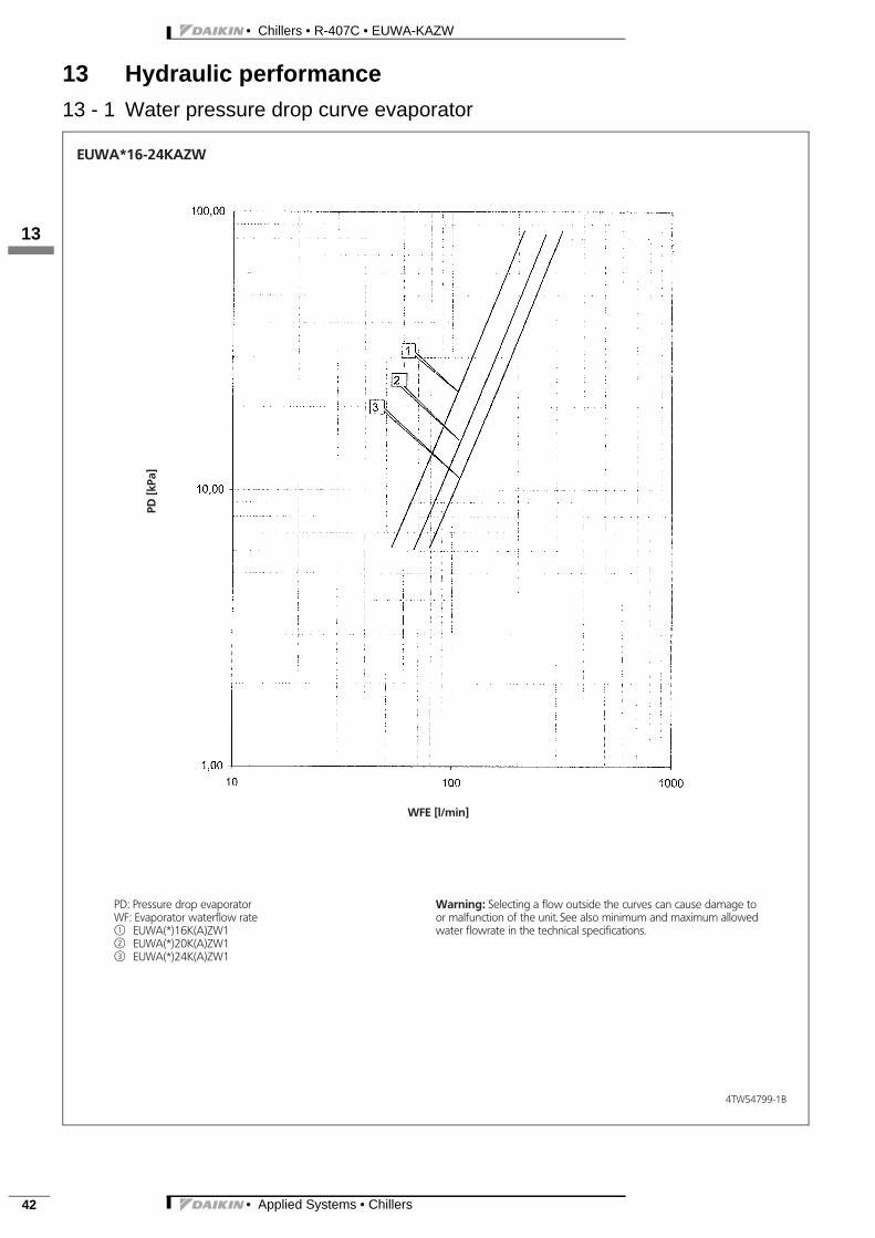
4TW54799-1B
PD: Pressure drop evaporatorWF: Evaporator waterflow ratej1 EUWA(*)16K(A)ZW1j2 EUWA(*)20K(A)ZW1j3 EUWA(*)24K(A)ZW1
PD[k
Pa]
WFE [l/min]
EUWA*16-24KAZW
Warning: Selecting a flow outside the curves can cause damage toor malfunction of the unit. See also minimum and maximum allowedwater flowrate in the technical specifications.

• Applied Systems • Chillers 43
• Chillers • R-407C • EUWA-KAZW
13 Hydraulic performance13 - 2 Water pressure drop curve unit
3
113
4TW55629-6
PD[k
Pa]
WF [l/min]
PD: Pressure drop through the unitWF: Evaporator waterflow ratej1 EUWAN5KAZW1j2 EUWAN8KAZW1j3 EUWAN10KAZW1j4 EUWAN12KAZW1
EUWAN5-12KAZW
Warning: Selecting a flow outside the curves can cause damage toor malfunction of the unit. See also minimum and maximum allowedwater flowrate in the technical specifications.
• Chillers • R-407C • EUWA-KAZW
• Applied Systems • Chillers44
13 Hydraulic performance13 - 2 Water pressure drop curve unit
113
4TW55669-6
PD[k
Pa]
WF [l/min]
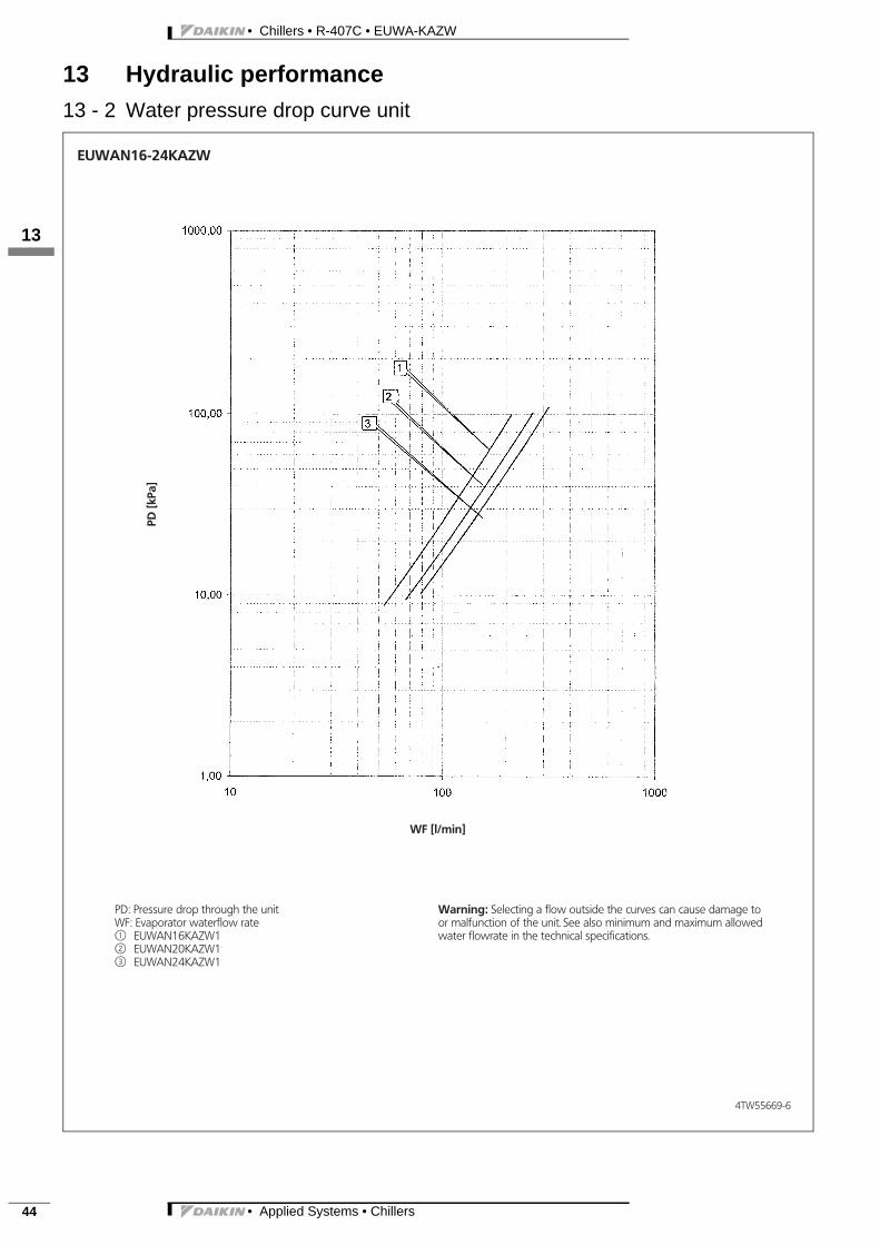
PD: Pressure drop through the unitWF: Evaporator waterflow ratej1 EUWAN16KAZW1j2 EUWAN20KAZW1j3 EUWAN24KAZW1
EUWAN16-24KAZW
Warning: Selecting a flow outside the curves can cause damage toor malfunction of the unit. See also minimum and maximum allowedwater flowrate in the technical specifications.
• Applied Systems • Chillers 45
• Chillers • R-407C • EUWA-KAZW
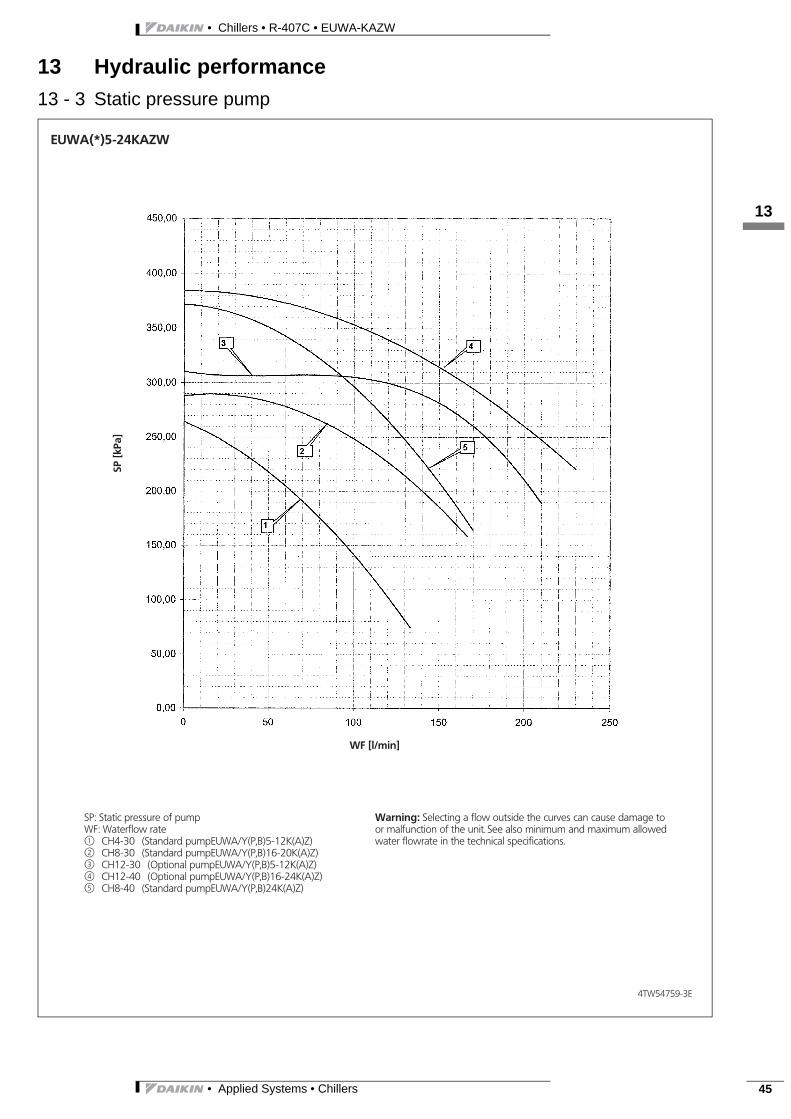
13 Hydraulic performance13 - 3 Static pressure pump
3
113
4TW54759-3E
SP[k
Pa]
WF [l/min]
SP: Static pressure of pumpWF: Waterflow ratej1 CH4-30 (Standard pumpEUWA/Y(P,B)5-12K(A)Z)j2 CH8-30 (Standard pumpEUWA/Y(P,B)16-20K(A)Z)j3 CH12-30 (Optional pumpEUWA/Y(P,B)5-12K(A)Z)j4 CH12-40 (Optional pumpEUWA/Y(P,B)16-24K(A)Z)j5 CH8-40 (Standard pumpEUWA/Y(P,B)24K(A)Z)
EUWA(*)5-24KAZW
Warning: Selecting a flow outside the curves can cause damage toor malfunction of the unit. See also minimum and maximum allowedwater flowrate in the technical specifications.
• Chillers • R-407C • EUWA-KAZW
• Applied Systems • Chillers46
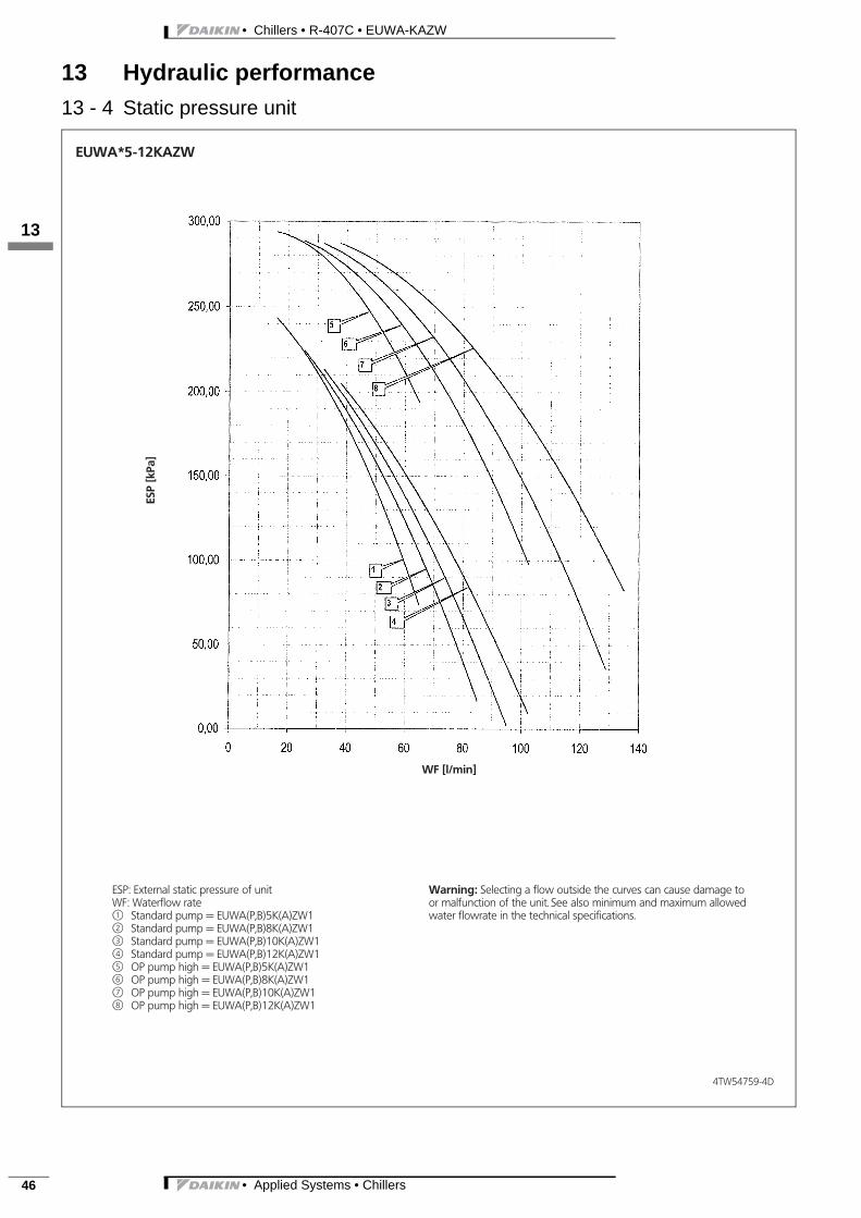
13 Hydraulic performance13 - 4 Static pressure unit
113
4TW54759-4D
ESP: External static pressure of unitWF: Waterflow ratej1 Standard pump = EUWA(P,B)5K(A)ZW1j2 Standard pump = EUWA(P,B)8K(A)ZW1j3 Standard pump = EUWA(P,B)10K(A)ZW1j4 Standard pump = EUWA(P,B)12K(A)ZW1j5 OP pump high = EUWA(P,B)5K(A)ZW1j6 OP pump high = EUWA(P,B)8K(A)ZW1j7 OP pump high = EUWA(P,B)10K(A)ZW1j8 OP pump high = EUWA(P,B)12K(A)ZW1
ESP
[kPa
]
WF [l/min]
EUWA*5-12KAZW
Warning: Selecting a flow outside the curves can cause damage toor malfunction of the unit. See also minimum and maximum allowedwater flowrate in the technical specifications.

• Applied Systems • Chillers 47
• Chillers • R-407C • EUWA-KAZW
13 Hydraulic performance13 - 4 Static pressure unit
3
113
4TW54799-4F
ESP: External static pressure of unitWF: Waterflow ratej1 Standard pump = EUWA(P,B)16K(A)ZW1j2 Standard pump = EUWA(P,B)20K(A)ZW1j3 Standard pump = EUWA(P,B)24K(A)ZW1j4 OP pump high = EUWA(P,B)16K(A)ZW1j5 OP pump high = EUWA(P,B)20K(A)ZW1j6 OP pump high = EUWA(P,B)24K(A)ZW1
ESP
[kPa
]
WF [l/min]
EUWA*16-24KAZW
Warning: Selecting a flow outside the curves can cause damage toor malfunction of the unit. See also minimum and maximum allowedwater flowrate in the technical specifications.