EE155/255 Green Electronics - Stanford University€¢ Now in the project part of the ... A...
63
EE155/255 Green Electronics Quiz Review 11/13/17 Prof. William Dally Computer Systems Laboratory Stanford University
Transcript of EE155/255 Green Electronics - Stanford University€¢ Now in the project part of the ... A...

EE155/255 Green Electronics
Quiz Review11/13/17
Prof. William DallyComputer Systems Laboratory
Stanford University

Course Logistics• Quiz is Wednesday 11/15
– 7:00PM to 9:00PM– Room ??– Covers all material to date– One page of notes allowed
• No Class on Wednesday• Now in the project part of the course
– Checkpoint 1 today – send the course staff an e-mail progress report – see Canvas• What you have accomplished• Any problems you encountered and how you dealt with them• Any revisions to your original plan• What you will do by Checkpoint 2
– PCB review by checkpoint 2– Order parts and PCBs ASAP– Make use of your project mentors

YAH
No Date Topic HWout HWin Labout Labck Lab HW1 9/25/17 Intro(basicconverters) 1 1 IntrotoST32F3 PeriodicSteadyState2 9/27/17 EmbeddedProg/PowerElect.3 10/2/17 PowerElectronics-1(switches) 2 1 2 1 ACEnergyMeter PowerDevices4 10/4/17 PowerElectronics-2(circuits)5 10/9/17 Photovoltaics 3 2 3 2 PVMPPT MotorcontrolMatlab6 10/11/17 FeedbackControl7 10/16/17 ElectricMotors 4 3 4 3 Motorcontrol-Lab/ Feedback8 10/18/17 IsolatedConverters9 10/23/17 SolarDay 5/PP 4 5 4 PS IsolatedConverters10 10/25/17 Magnetics11 10/30/17 Inverters,Grid,PF,andBatteries 6 5/PP 6 5 Magnetics MagneticsandInverters12 11/1/17 ProjectDiscussions13 11/6/17 Thermal&EMI 6 P 6 Project14 11/8/17 Grounding,andDebugging15 11/13/17 QuizReview C116 11/15/17 NoClassQ 11/15/17 Quiz-intheevening
11/20/17 ThanksgivingBreak C211/22/17 ThanksgivingBreak
17 11/27/17 JonWagner-Joby18 11/29/17 MartinFornage-Enphase C319 12/4/17 ColinCampbell-Tesla20 12/6/17 NoClass C4
TBD Projectpresentations P12/15/17 Projectwebpagedue

Quiz Review

Periodic Steady State

Buck Converter
L
V2
+-
iLV1
+-
a
b

Dual-Source Buck
ab
c

V6.0 Page
2
Problem1:PeriodicSteadyStateAnalysis[15Points]
Considertheconvertershowninthedrawingabove.Thethree-positionswitchoperateswithacycletimeoftc=10µs,hasadutyfactorinposition1ofD1,adutyfactorinposition2ofD2,andadutyfactorinposition3ofD3.D1+D2+D3=1.Theinductoris1µHandbothcapacitorsare100µF.SourceV1is1V.Andinsteadystate,thevoltageacrossC2is2V.
(a) [5Points]Iftheconverterisinperiodicsteadystate,whatisthevoltageacrossthecapacitorC1?Giveyouranswerintermsofthedutyfactors.
(b) [10Points,5PointsEach]WriteexpressionsforthechangeininductorcurrentDIandthechangeincapacitorC1voltageDVoveronecycleoftheswitchwhennotintheperiodicsteadystate.
(c) [5points]WhatisthenaturalfrequencyoftheresponseoncapacitorC1toatransientindutyfactor.

Isolated Converters

Ideal Transformer
1:NIP
VP
IS
VS
+ +
62 Green Electronics
1:NIP
VP
IS
VS
+ +
Figure 10.1: An ideal transformer with turns ratio 1 : N maintains the relation-ships VS = NVP and IS = IP
N .
inductance in an ideal transformer. The transformer is a four-terminal device,the left two terminals are connected to the primary winding of the transformer.The right two terminals are connected to the secondary winding.
The dots in the symbol indicate the polarity of the windings. When a voltageVP is applied to the primary so that the terminal labeled with the dot is positive(as shown), a voltage VS will appear at the secondary with the dotted terminalpositive as well. When the primary is driven so that current IP flows into thedotted terminal, current IS flows out of the dotted terminal of the secondary.
A transformer is characterized by its turns ratio, NP : NS . Physically this isthe ratio of the number of turns in the primary and secondary windings. Elec-trically, this ratio determines the ratio of voltages and currents in the primaryand secondary. For an ideal transformer, the primary and secondary voltagesand currents are related by
VS =NS
NPVP (10.1)
IS =NP
NSVP (10.2)
An ideal transformer with a 1 : N turns ratio, as depicted in Figure 10.1 stepsup the voltage by N and steps down the current by N so that the power intothe primary is equal to the power out of the secondary
PS = VSIS =NS
NPVP
NP
NSIP = VP IP = PP (10.3)
A transformer does not have a preferred direction. Current, and power, canflow in either direction. If you reverse the primary and secondary of Figure 10.1you have a transformer with a N : 1 turns ratio.
Similarly the voltage of a transformer is not necessarily set by its primaryterminal, or even by a single set of terminals. A transformer always maintainsa voltage ratio between its terminals that is set by its turns ratio. However, in

Real Transformer
1:NiP
VP
iS
VS
+ +
LMiM
LL
VPR
+ideal xfmr
iPR

Full-Bridge Converter
1:N
iP
VP
+
inverter
V1+
b b
aa
transformer
d d
c c
V2+L
iS
iL
rectifier output filter
C
VS
+VR
+

Full-Bridge Converter
UL UR
LL LR
EE 155/255 Lecture 8 - Isolated Converters

Periodic Steady State Analysis of Full Bridge
• Suppose V1 = 10V, transformer is 1:10, what duty factor gives V2=50V (ignoring leakage inductance)
• Now if primary referenced leakage inductance is 10µH iL = 10A, tcy = 10µs, what duty factor is needed?

Flyback Converter
1:N
VS
+
LM
a+
C V2
b
V1
+
iM VP
+
LL iL
x
EA
iS
VPR
+
EE 155/255 Lecture 8 - Isolated Converters

Flyback ConverterWith LM and LL and Transformer Eliminated
LM
a
+
CNV2
V1
+
iM
LL iL
x
EA
iS
N
EE 155/255 Lecture 8 - Isolated Converters

Flyback Converter• Assume no leakage inductance• Magnitizing inductance is 50uH• Input voltage and output voltage both 100V• If 1A load current, 16us cycle time, and 1:1 transformer• How long an on period is required?
V6.0 Page
7
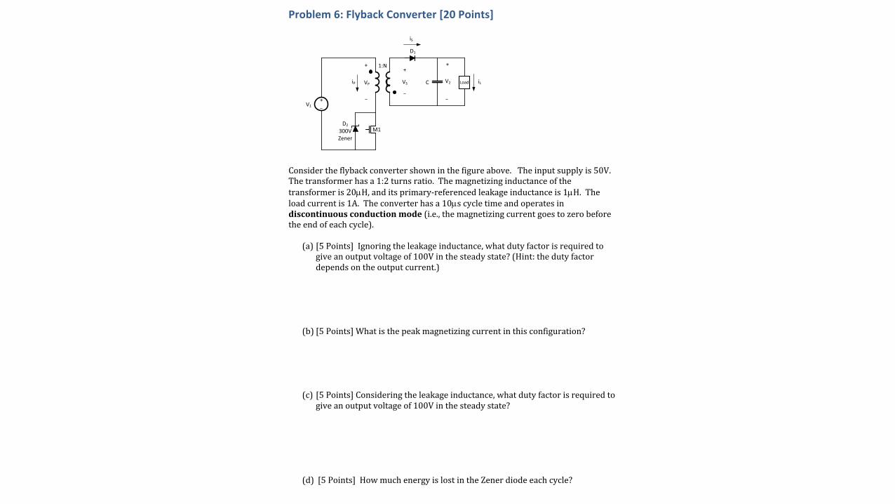
Problem6:FlybackConverter[20Points]
Considertheflybackconvertershowninthefigureabove.Theinputsupplyis50V.Thetransformerhasa1:2turnsratio.Themagnetizinginductanceofthetransformeris20µH,anditsprimary-referencedleakageinductanceis1µH.Theloadcurrentis1A.Theconverterhasa10µscycletimeandoperatesindiscontinuousconductionmode(i.e.,themagnetizingcurrentgoestozerobeforetheendofeachcycle).
(a) [5Points]Ignoringtheleakageinductance,whatdutyfactorisrequiredtogiveanoutputvoltageof100Vinthesteadystate?(Hint:thedutyfactordependsontheoutputcurrent.)
(b) [5Points]Whatisthepeakmagnetizingcurrentinthisconfiguration?
(c) [5Points]Consideringtheleakageinductance,whatdutyfactorisrequiredtogiveanoutputvoltageof100Vinthesteadystate?
(d) [5Points]HowmuchenergyislostintheZenerdiodeeachcycle?
1:N
VS
++
C V2
V1
+
VP
+
iP
iS
D1
M1D2
300V Zener
Load iLL

Motor Control

Motor Equations
V = |L|(v x B) V = KMw
F = i(L x B)t = KMi
t = IM(dw/dt)
Simultaneously both a motor and a generator

Back EMF
N
S
1
23
V(a) = -Kwsin(q-a)
Open-circuit voltage (back EMF) of each phase is a sinusoid that
Is proportional to w
Reaches peak value when rotor is 90 degrees from phase.

Torque
N
S
1
23
t = -(Ki)sin(q-ai)
Torque is proportional to current
Torque is maximum when rotor is 90 degrees behind phase
Torque from each phase is sinusoidal

Example• Suppose KM=1, RM=1, q=30deg, w=10rad/s, V=100V• What duty factor should be applied to each phase to give 1N-m torque?

Three-Phase Explained Graphically
0 50 100 150 200 250 300 350 400−1
−0.5
0
0.5
1
0 50 100 150 200 250 300 350 4000
0.2
0.4
0.6
0.8
1
0 50 100 150 200 250 300 350 400−2
−1.5
−1
−0.5
0
0.5
1
1.5
2
Sin(q-fi)
Sin2(q-fi)
SSin2(q-fi)
Current
Torque
Sum of Torque over phases

V6.0 Page
3
Problem2:Motors[20Points–5pointseach]
Supposeyouhaveasingle-phasebrushlesspermanentmagnetmotor(asshownabove).Therotorisshownintheq=0position.Youmayneglecttheinductanceinthemotorwindings.
(a) Whenthemotorhasanangularvelocityofw=2rad/syouobserveasinewavewithamplitude1V(RMS)andfrequencyof2rad/sacrossthesingleopen-circuitwinding.Ifyouincreasetheangularvelocitytow = 4 rad/s,whatvoltagewaveformwillyouseeacrossthewinding?(Expressvoltageasafunctionoftime,t).
(b) Youapplyatorqueof2N-mtotheshaftofthemotorrotatingat10rad/sinthedirectionofrotation.Whatresistancemustbeappliedacrossthewindingtokeepthemotoratasteadyspeed?
(c) DrivingthewindingwithaDCcurrentsourcewithcurrentI0andtherotor“locked”inastationaryposition,youobserveatorqueof1N-mwiththerotoratq=30degrees.Whattorquedoyouexpectwiththesamecurrentandtherotoratq=90degrees?
(d) Whattorquedoyouexpectatq=90degreesandacurrentof2I0?
N
S
phi1

Control

Consider the Following Plants
1
s+ a
1
s2 + 2⇣!s+ !2
1
What type of controller do we need for each?
What should the parameters of our controller be?

Bode Plot for z=0.1 w=1000
−20
−10
0
10
20
30
40
Mag
nitu
de (d
B)
102 103 104−180
−135
−90
−45
0
Phas
e (d
eg)
Bode DiagramGm = Inf dB (at Inf rad/s) , Pm = 3.8 deg (at 3.31e+03 rad/s)
Frequency (rad/s)

Approach 1 – Integral Only – Low Gain
−140
−120
−100
−80
−60
−40
Mag
nitu
de (d
B)
102 103 104−270
−225
−180
−135
−90
Phas
e (d
eg)
Bode DiagramGm = 66 dB (at 1e+03 rad/s) , Pm = 90 deg (at 0.1 rad/s)
Frequency (rad/s)

Approach 2 – PDI – Large Gain Compensating Zero
−20
0
20
40
60
80
100
Mag
nitu
de (d
B)
10−1 100 101 102 103 104 105 106−135
−90
−45
0
45
Phas
e (d
eg)
Bode DiagramGm = Inf , Pm = 89.5 deg (at 1e+05 rad/s)
Frequency (rad/s)

V6.0 Page
5
Problem4:FeedbackControl[20Points]
Youhaveaplantwiththeopen-loopfrequencyresponseasshownintheBodeplotabove.TheDCgainis104,thereisonepoleat-1rad/s,andonepoleat-2rad/s.Supposeyoucloseafeedbacklooparoundthissystem.Answerthefollowingquestionsabouttheresultingsystem:(a)[5Points]Isthesystemadequatelydamped,i.e.,willanyringingafteranabrupttransitiondieoutinatmostacycleortwo?(yes/no)(b)[5Points]Atwhatfrequencyin(rad/s)willanyringingoccur?(c)[5Points]AddaPDcontrollertothesystemleavingtheDCgainunchanged(i.e.,P=1).Whatisthesmallestderivativegainyoucanaddthatwillgiveaphasemarginofatleast60degrees?(Anapproximateanswer(withinafactorof2)isOK.Youneednotbeexact.)(d)[5Points]Whatisthefrequencyofthezeroyouaddedinpart(c)?

Switches

DC I-V Characteristics of On Switches
V(d)0.0V 0.1V 0.2V 0.3V 0.4V 0.5V 0.6V 0.7V 0.8V 0.9V 1.0V 1.1V 1.2V 1.3V 1.4V 1.5V 1.6V 1.7V 1.8V 1.9V 2.0V
0A
5A
10A
15A
20A
25A
30A
35A
40A
45A
50AIx(m:1) Ix(h:2) Ix(i:C) I(Dd)
600V FETFCB36N60
600V IGBTFGH40N60
400V DiodeSTTH20R04
60V FETIRLB3036
FETs CharacterizedBy RON
IGBT Like a DiodeLittle Current Until ~0.7V
HV FET has high RONR ~ kV2
Diode and IGBTResistive at high Current

Transient Response of FET and IGBT
0ns 40ns 80ns 120ns 160ns 200ns 240ns 280ns 320ns0V
50V
100V
150V
200V
250V
300V
350V
400V
450V
500V
550V
0A
5A
10A
15A
20A
0V
50V
100V
150V
200V
250V
300V
350V
400V
450V
500V
550V
0A
5A
10A
15A
20A
0KW
1KW
2KW
3KW
4KW
5KW
6KW
7KW
8KW
9KW
10KW
V(di) Ix(i:C)
V(dm) Ix(h:2)
ix(i:c)*v(di) ix(h:2)*V(dm)
600V FETFCB36N60
InstantaneousPower
Turn On Turn Off
600V IGBTFGH40N60
36µJ 36µJ92µJ 428µJ

Turn-OnBuck w/ Diode
IP
ILQRR QD
ID
VDS
s
t1 t2 t3
t1 – ramp current to IL
t2 – diode reverse recovery
t3 – discharge drain capacitance
Current waveform in t2 and t3 may vary

Turn-OnBuck w/ Diode
t1 =ILs
E1 = 0.5VDDILt1 =0.5VDDIL
2
s
t2 =2QRR
sE2 =VDDt2 IL + 0.5t2s( )
t3 ≈2QD
IPE3 = 0.5VDDQD + 0.33VDDILt3
IP
ILQRR QD
ID
VDS
s
t1 t2 t3

Switches• Calculate the switching energy during turn-on for a MOSFET switching
10A through 100V in a buck configuration. Drain capacitance is 1nF, QRR is 25nC. Current ramp is 1A/ns.

V6.0 Page
4
Problem3:FETLosses[10points,5pointseach]
Considertheboostconvertershownaboveoperatingintheperiodicsteadystatewitha100kHzswitchingfrequencyfcy.SupposetheMOSFEThasaRonof100mWandswitcheswithalinearcurrentrampof1A/nsforbothturn-onandturn-off.AssumethatthecapacitanceonthedrainoftheMOSFETisalinear100pFcapacitorandthatdutyfactorD=0.5.Assumethediodehaszeroforwardvoltagedropandnoreverserecoverycharge(i.e.,itswitchesoffinstantly).Assumethattheinductorandcapacitorareidealandthatripplecurrentisnegligible.Computetheswitchinglossandconductionlossofthisconverter.Youmayignoreturn-offlosses.
DUTG 500V
+-
20A


PV• Suppose a single PV panel has
– VOC = 40V, ISC = 8A, and Pmax = 250W • You want to use this panel to provide a 5V supply with the maximum possible current(a) What converter topology should you use?(b) What variable should be regulated?(c) If losses are zero, what will be the maximum current out?(d) Will the panel be at its MPP when current reaches a maximum?(xc) What control law will provide maximum power beyond the point where 5V can be maintained?
(e) What would your answers be if the output were 100V?

IV Curve from SPICE Model

Typical String of 10 PV Panels

V6.0 Page
8
Problem7:Photovoltaics[15Points,3PointsEach]
SupposeIhaveastringof3PVmodules.ThefirsttwohaveI-Vcharacteristicsgivenbythe1000W/m2lineonthefigureabove.Thethirdfollowsthe400W/m2line.Thethreemodulesareconnectedwithbypassdiodesacrosseachmodule.Answereachofthefollowingquestionsaboutthisthreemoduleconfiguration.(a)Whatistheapproximateopen-circuitvoltageofthe3-panelconfiguration?(b)Whatistheapproximateshort-circuitcurrentofthe3-panelconfiguration?(c)Atthelowestcurrentwherethe400W/m2panelbypasses,whatareIandV?(d)WhatistheapproximatemaximumpowerpointMPPofthethree-panelconfiguration?(e)Canthemaximumpowerpointbefoundbygradientsearch(hillclimbing)fromboththeopen-circuitandshort-circuitconfigurations?(yesorno,andexplain)
2Under Standard Test Conditions (STC) of irradiance of 1000W/m , spectrum AM 1.5 and cell temperature of 25℃
*Specifications included in this datasheet are subject to change without prior notice.
Engineering Drawings
I-V Curves (CS6P-235PX)
Temperature Coefficient
About Canadian Solar
Headquarters | 650 Riverbend Drive, Suite BKitchener, Ontario | Canada N2K 3S2Tel: +1-519-954-2057Fax: [email protected]
CS6P-235PXElectrical Data
PmaxVocIsc
-0.43 ℃
-0.34 %/℃0.065 %/℃
45±2℃
%/
Temperature Characteristics
CS6P-235PX170W27.2V6.27A33.9V6.86A
NOCTNominal Maximum Power (Pmax)Optimum Operating Voltage (Vmp)Optimum Operating Current (Imp)Open Circuit Voltage (Voc)Short Circuit (Isc)Current
2Under Normal Operating Cell Temperature, Irradiance of 800 W/m , spectrum AM 1.5, ambient temperature 20 , wind speed 1 m/s
℃
Performance at Low Irradiance
Normal Operating Cell Temperature
Mechanical DataCell Type
Cell Arrangement
Dimensions
Weight
Front Cover
Frame Material
J-BOX
Cable
Connectors
Standard Packaging (Modules per Pallet)
Module Pieces per container (40 ft . Container)
Industry leading performance at low irradiation environment, +95.5% module efficiency from an
2 2 irradiance of 1000w/m to 200w/m(AM 1.5, 25 ℃)
EN-Rev 10.16 Copyright 2011 Canadian Solar Inc.
Canadian Solar Inc. is one of the world's largest solar c o m p a n i e s . A s a l e a d i n g v e r t i c a l l y - i n t e g r a t e d manufacturer of ingots, wafers, cells, solar modules and solar systems. Canadian Solar delivers solar power products of uncompromising quality to worldwide customers. Canadian Solar's world class team of professionals works closely with our customers to provide them with solutions for all their solar needs.
Canadian Solar was founded in Canada in 2001 and was successfully listed on NASDAQ Exchange (symbol: CSIQ) in November 2006. Canadian Solar will expand its module manufacturing capacity to 2.05GW and cell manufacturing capacity to 1.3GW in 2011.
Section B-B
Section A-A
A A
BB
STCNominal Maximum Power (Pmax)Optimum Operating Voltage (Vmp)Optimum Operating Current (Imp)Open Circuit Voltage (Voc)Short Circuit (Isc)Module EfficiencyOperating TemperatureMaximum System Voltage Maximum Series Fuse RatingApplication ClassificationPower Tolerance
Current
-40℃~+85℃1000V (IEC) /600V (UL)
15AClass A0 ~ +5W
CS6P-235PX235W29.8V7.90A36.9V8.46A
14.61%
Poly-crystalline 156 156mm
60 (6 x 10)
1638 x 982 x 40mm (64.5 x 38.7 x 1.57in)
20kg (44.1 lbs)
3.2mm Tempered glass
Anodized aluminium alloy
IP65, 3 diodes
4mm (IEC)/12AWG(UL), 1100mm
MC4 or MC4 Comparable
24pcs
672pcs (40'HQ)
x , 2 or 3 Busbars
2

Magnetic Components

A Magnetic Circuit• Put N turns of wire on a magnetic core• Pass current i through resulting coil• Produces Magnetomotive Force
• F induces a flux f in the core
• Where R is the Reluctance of the core
• Change in f causes voltage
F = Ni
φ =FR
=NiR
V = N dφdt

Two Key Equations

Inductors• Suppose inductor for a converter with L=6.25uH and Imax=11A has• Ac = 1E-4m2
• Lc = 1E-2m• µ = 1000• f = 100kHz• Bmax = 0.1T
• What gap is needed? How many turns?

Transformers
V = Nd�
dt
V T = N�
V T = NBA
N =V T
BA
1
1:NiP
VP
iS
VS
+ +LM
iM
LL
VPR
+
ideal xfmr
iPR

V6.0 Page
6
Problem5:TransformerDesign[20Points,5PointsEach]TherelevantpropertiesforaFerroxcubeE20/10/5coreareshowninthetablebelow.Inthe3C96materialthiscorehasaµr=1530andAL=1.4µH/turns2.ThewindowareaisAW=100mm2,andthelengthoftheaverageturnisLturn=38mm.Recallthepermeabilityoffreespaceµ0=4px10-7.
(a)Supposeyoubuildatransformerbywindinga5-turnprimaryanda40-turnsecondaryonthiscore.Whatistheprimary-referencedmagnetizinginductanceofthistransformer?(Hint:useAL).(b)Startingfromzeromagnetizingcurrent,howmanyVolt-Secondscantheprimaryofthetransformerofpart(a)toleratebeforetheB-fieldinitscorereaches0.5T?(c)Forthecoretohandle10-4Volt-Seconds,howmanyturnswouldtheprimaryneedtohave?(d)Fortheconfigurationofpart(a),whatisthesecondary-referencedmagnetizinginductanceofthetransformer?
)HUUR[FXEH
(�FRUHV�DQG�DFFHVVRULHV (�������
CORE SETS
Effective core parameters
SYMBOL PARAMETER VALUE UNITΣ�,�$� FRUH�IDFWRU��&�� ���� PP−�
9H HIIHFWLYH�YROXPH ���� PP�
,H HIIHFWLYH�OHQJWK ���� PP$H HIIHFWLYH�DUHD ���� PP�
$PLQ PLQLPXP�DUHD ���� PP�
P PDVV�RI�FRUH�KDOI ≈ ��� J
)LJ����(��������FRUH�KDOI�
'LPHQVLRQV�LQ�PP�
handbook, halfpage
5�
CBW016
5�≤���� ���±���
�����+�������
����+�������
�����������−���
����������−���
����������−���
Core halves&ODPSLQJ�IRUFH�IRU�$/�PHDVXUHPHQWV���� ±�� 1�
GRADE AL(nH) µe
AIR GAP(µm) TYPE NUMBER
�&�� �� ±�� ≈ �� ≈ ��� (���������&���$����� ±�� ≈��� ≈ ��� (���������&���$������ ±�� ≈��� ≈ ��� (���������&���$������ ±��� ≈ ��� ≈��� (���������&���$������ ±��� ≈ ��� ≈��� (���������&���$���
���� ±��� ≈���� ≈ � (���������&���&�� ���� ±��� ≈���� ≈ � (���������&���&�� ���� ±��� ≈���� ≈ � (���������&���&�� ���� ±��� ≈���� ≈ � (���������&���)� �� ±�� ≈ �� ≈ ��� (���������)��$��
��� ±�� ≈ ��� ≈ ��� (���������)��$������ ±�� ≈��� ≈ ��� (���������)��$������ ±��� ≈ ��� ≈��� (���������)��$������ ±��� ≈ ��� ≈��� (���������)��$���
���� ±��� ≈���� ≈ � (���������)��)�� ���� ±��� ≈���� ≈ � (���������)��
2013 Jul 31 228

Soft Switching

Soft Switching• Only switch a FET when:
– Zero voltage across it (ZVS)– Zero current through it (ZCS)– Both
• 4 Approaches– Phase-shifted full-bridge– Quasi-square wave– Quasi resonant– Active clamp

QSW Buck Converter
L
iLVS
+-
vC Load
+
-
C iLoadM2L
M1H
CX
D1
D2

Soft Switched Waveforms

Inverters and Power Factor

Definition
�I = (Vin �DhVd)tcy
L
i(s) = �dh(s)hVdisL
� vd(s)hDhisL
�Vd =
✓DhI �
Vd
R
◆tcy
C
vd(s) =hDhii(s)
sC� vd(s)
sRC
vd(s)
✓1 +
1
sRC
◆=
hDhii(s)sC
vd(s) (sRC + 1) = hDhiRi(s)
vd(s) =hDhiRi(s)
sRC + 1=
hDhii(s)sC + 1
R
vd(s) = �hDhihVdidh(s) + hDhi2vd(s)s2LC + s
LR
vd(s)
✓s2LC + s
L
R+ hDhi2
◆= �hDhihVdidh(s)
vd(s)
dh(s)= � hDhihVdi
s2LC + sLR + hDhi2
vd(s)
dh(s)= �
hDhihVdiLC
s2 + s1
RC + hDhi2LC
PF =Real Power
Apparent Power
PF =Pp
P 2 +Q2
PF =1p
1 + THD2=
I1,rms
Irms
1
Apparent Power = Vrms x Irms

Make a PWM Sine Wave and Filter

PWM Synthesis
0 2 4 6 8 10 12 14 16−1
−0.5
0
0.5
1
1.5
V AC, V
Saw (V
)
0 2 4 6 8 10 12 14 16−1
−0.5
0
0.5
1
V PWM
(V)
0 2 4 6 8 10 12 14 16−1.5
−1
−0.5
0
0.5
1
1.5
V Out
(V)
0 2 4 6 8 10 12 14 16−1
−0.5
0
0.5
1
I L (A)
t (ms)
x = sine > sawy = -sine > saw
Digitally generate sine with quarter-wave table

Spectrum of 100kHz PWM Signal
101 102 103 104 105 1060
1
2
3
4
5
6
7
8
9x 10⁵
f (Hz)
Mag

Batteries

Batteries
LB RB
VBS VB
+
-

Voltage Surface V(x,T,I)
/LWKLXP�LRQ5HFKDUJHDEOH��EDWWHU\
3.5
4.0
4.5
/ V
Discharge Temperature Characteristics for NCR18650B1Scell-1 Charge:CC-CV:1.625A-4.20V(65.0mA cut)
Discharge:CC:3.25A(E.V.:2.50V)1.-20Υ 2.-10Υ 3.0Υ 4.25Υ 5.40Υ 6.45Υ 7.60Υ
Discharge Rate Characteristics for NCR18650BCharge:CC-CV:1.625A-4.2V (65.0mA cut)Discharge:CC:Variable Current (E.V.:2.50V)Temp:25Υ
2G23X0KYKU
0 500 1000 1500 2000 2500 3000 3500 4000Discharge Capacity / mAh
2.0
2.5
3.0
3.5
Cel
l Vo
ltage
2.0CA 1.0CA 0.5CA 0.2CA
/LWKLXP�LRQ5HFKDUJHDEOH��EDWWHU\
3.5
4.0
4.5e
/ V
Discharge Temperature Characteristics for NCR18650B1Scell-1 Charge:CC-CV:1.625A-4.20V(65.0mA cut)
Discharge:CC:3.25A(E.V.:2.50V)1.-20Υ 2.-10Υ 3.0Υ 4.25Υ 5.40Υ 6.45Υ 7.60Υ
Discharge Temperature Characteristics for NCR18650B
2G23X0KYKU
0 500 1000 1500 2000 2500 3000 3500 4000Discharge Capacity / mAh
2.0
2.5
3.0
3.5
Ce
ll V
olta
ge
40Υ 25Υ 0Υ -10Υ -20Υ

Charge Cycle /LWKLXP�LRQ5HFKDUJHDEOH��EDWWHU\
3.5
4.0
4.5
e /
V
3000
4000
5000
mA
3000
4000
mA
h
3.5
4.0
4.5
e /
V
3000
4000
5000
mA
Charge Characteristics for NCR18650B1S
No.1 Charge:CC-CV:1.625A-4.20V(65.0mA cut)
Cell Voltage
Charge Characteristics for NCR18650B
2G23X0KYKU
0 60 120 180 240Charge Time / min
2.0
2.5
3.0
3.5
Ce
ll V
olta
ge
0
1000
2000
3000
Cu
rre
nt
/ m
1000
2000
3000
Ca
pa
city
/ m
0 60 120 180 240Charge Time / min
2.0
2.5
3.0
3.5
Ce
ll V
olta
ge
0
1000
2000
3000
Cu
rre
nt
/ m
Capacity
45Υ 25Υ 0Υ
Current

YAH
No Date Topic HWout HWin Labout Labck Lab HW1 9/25/17 Intro(basicconverters) 1 1 IntrotoST32F3 PeriodicSteadyState2 9/27/17 EmbeddedProg/PowerElect.3 10/2/17 PowerElectronics-1(switches) 2 1 2 1 ACEnergyMeter PowerDevices4 10/4/17 PowerElectronics-2(circuits)5 10/9/17 Photovoltaics 3 2 3 2 PVMPPT MotorcontrolMatlab6 10/11/17 FeedbackControl7 10/16/17 ElectricMotors 4 3 4 3 Motorcontrol-Lab/ Feedback8 10/18/17 IsolatedConverters9 10/23/17 SolarDay 5/PP 4 5 4 PS IsolatedConverters10 10/25/17 Magnetics11 10/30/17 Inverters,Grid,PF,andBatteries 6 5/PP 6 5 Magnetics MagneticsandInverters12 11/1/17 ProjectDiscussions13 11/6/17 Thermal&EMI 6 P 6 Project14 11/8/17 Grounding,andDebugging15 11/13/17 QuizReview C116 11/15/17 NoClassQ 11/15/17 Quiz-intheevening
11/20/17 ThanksgivingBreak C211/22/17 ThanksgivingBreak
17 11/27/17 JonWagner-Joby18 11/29/17 MartinFornage-Enphase C319 12/4/17 ColinCampbell-Tesla20 12/6/17 NoClass C4
TBD Projectpresentations P12/15/17 Projectwebpagedue