EE130/230A Discussion 6
15
EE130/230A Discussion 6 Peng Zheng
-
Upload
dolan-lowery -
Category
Documents
-
view
48 -
download
1
description
EE130/230A Discussion 6. Peng Zheng. Carrier Action under Forward Bias. When a forward bias ( V A >0) is applied, the potential barrier to diffusion across the junction is reduced Minority carriers are “injected” into the quasi-neutral regions => D n p > 0, D p n > 0 - PowerPoint PPT Presentation
Transcript of EE130/230A Discussion 6

EE130/230A Discussion 6
Peng Zheng

Carrier Action under Forward Bias
• When a forward bias (VA>0) is applied, the potential barrier to diffusion across the junction is reduced– Minority carriers are “injected” into the quasi-neutral regions => Dnp > 0, Dpn > 0
• Minority carriers diffuse in the quasi-neutral regions, recombining with majority carriers
Lecture 10, Slide 2EE130/230A Fall 2013

Components of Current Flow• Current density J = Jn(x) + Jp(x)
• J is constant throughout the diode, but Jn(x) and Jp(x) vary with position:
dx
ndqDnq
dx
dnqDnqxJ nnnnn
)()(
dx
pdqDpq
dx
dpqDpqxJ ppppp
)()(
Lecture 10, Slide 3
xJN
xn-xp
JExample: p+n junction under forward bias:
JP
EE130/230A Fall 2013

Excess Carrier Concentrations at –xp, xn
1)(
)(
)(
/
A
2
/0
A
/2
A
A
A
A
kTqVipp
kTqVp
kTqVi
pp
pp
eN
nxn
en
N
enxn
Nxp
n sidep side
1)(
)(
)(
/
D
2
/0
D
/2
D
A
A
A
kTqVinn
kTqVn
kTqVi
nn
nn
eN
nxp
ep
N
enxp
Nxn
Lecture 10, Slide 4EE130/230A Fall 2013

Carrier Concentration Profiles under Forward Bias
Lecture 10, Slide 5R. F. Pierret, Semiconductor Device Fundamentals, Fig. 6.8a
EE130/230A Fall 2013

Excess Carrier Distribution (n side)
• From the minority carrier diffusion equation:
• We have the following boundary conditions:
• For simplicity, use a new coordinate system:
• Then, the solution is of the form:
0)( np)1()( / kTqVnonn
Aepxp
22
2
p
n
pp
nn
L
p
D
p
dx
pd
pp LxLxn eAeAxp /'
2/'
1)'(
NEW: x’’ 0 0 x’
Lecture 10, Slide 6EE130/230A Fall 2013

From the x = boundary condition:
From the x = xn boundary condition:
Therefore
Similarly, we can derive
0' ,)1()'( /'/ xeepxp pALxkTqV
non
pp LxLxn eAeAxp /'
2/'
1)'(
0'' ,)1()''( /''/ xeenxn nA LxkTqVpop
Lecture 10, Slide 7EE130/230A Fall 2013
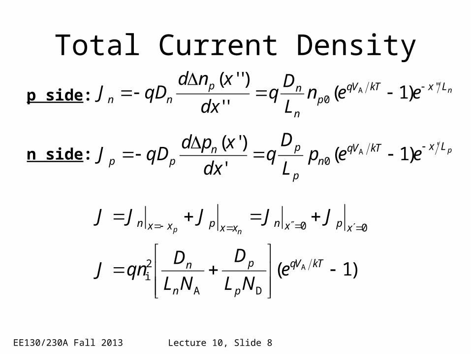
Total Current Density
pLxkTVqn
p
pnpp eep
L
Dq
dx
xpdqDJ '
0 )1('
)'(A
nLxkTVqp
n
npnn een
L
Dq
dx
xndqDJ ''
0 )1(''
)''(A
n side:
p side:
)1( A
DA
2i
00
kTVq
p
p
n
n
xpxnxxpxxn
eNL
D
NL
DqnJ
JJJJJnp
Lecture 10, Slide 8EE130/230A Fall 2013

Summary: Long-Base Diode• Under forward bias (VA > 0), the potential barrier to carrier
diffusion is reduced minority carriers are “injected” into the quasi-neutral regions.– The minority-carrier concentrations at the edges of the depletion region
change with the applied bias VA, by the factor– The excess carrier concentrations in the quasi-neutral regions decay to
zero away from the depletion region, due to recombination.
pn junction diode current
• I0 can be viewed as the drift current due to minority carriers generated within a diffusion length of the depletion region
kTqVAe /
Lecture 10, Slide 9
)1( A
DA
2i
kTVq
p
p
n
n eNL
D
NL
DqAnI
EE130/230A Fall 2013

General Narrow-Base Diode I-V• Define WP‘ and WN’ to be the widths of the quasi-neutral regions.• If both sides of a pn junction are narrow (i.e. much shorter than
the minority carrier diffusion lengths in the respective regions):
11 /0
/2
kTqVkTqV
AP
N
DN
Pi
AA eIeNW
D
NW
DqAnI
Lecture 11, Slide 10
xJN
xn-xp
JJP
e.g. if hole injection into the n side is greater than electron injection into the p side:
EE130/230A Fall 2013

Summary: Narrow-Base Diode• If the length of the quasi-neutral region is much shorter than the
minority-carrier diffusion length, then there will be negligible recombination within the quasi-neutral region and hence all of the injected minority carriers will “survive” to reach the metal contact.– The excess carrier concentration is a linear function of distance.
For example, within a narrow n-type quasi-neutral region:
The minority-carrier diffusion current is constant within the narrow quasi-neutral region.
Shorter quasi-neutral region steeper concentration gradient higher diffusion current
)1( / kTqVno
Aep
x
Dpn(x)
xn0
location of metal contact(Dpn=0)
WN’
EE130/230A Fall 2013 Lecture 11, Slide 11

Sample ProblemConsider a Si pn step junction diode maintained at room temperature, with p-side and n-side dopant concentrations NA = 1016 cm-3 and ND = 21016 cm-3, respectively. (You may assume that each side is uncompensated.) The minority carrier recombination lifetimes are tn = 10-6 s and tp=10-7 s on the p-side and n-side, respectively. Applied bias VA is (kT/q)*ln(108) 0.48V.


What if the n-side is a short base?
The hole diffusion component of the diode saturation current is calculated using the short-base diode formula:
I0,p = Aqni2Dp/(Wn’×ND)
ref. slide 10


![EE130/230A Discussion 3 Peng Zheng. Conductivity of a Semiconductor EE130/230A Fall 2013 n [q mn / m n *] is the electron mobility p [q mp.](https://static.fdocuments.us/doc/165x107/56649f3e5503460f94c5e5e7/ee130230a-discussion-3-peng-zheng-conductivity-of-a-semiconductor-ee130230a.jpg)