Edition 05/2018 SEW-EURODRIVE Easy Guide · Brief information X.. Series Helical and Bevel-Helical...
16
Brief information X.. Series Helical and Bevel-Helical Gear Units 24803731/ EN Edition 05/2018 SEW-EURODRIVE Easy Guide Industrial Gear Units
Transcript of Edition 05/2018 SEW-EURODRIVE Easy Guide · Brief information X.. Series Helical and Bevel-Helical...

Brief information
X.. Series Helical and Bevel-Helical Gear Units
24803731/ EN Edition 05/2018
SEW-EURODRIVE Easy Guide
Industrial Gear Units

The illustrations shown serve as examples.
NOTICE: This document does not replace the detailed applicable operating instructions.
Brief information X.. Series Industrial Gear Units
Mounting positions
Nameplate Safety symbols on the gear unit
3 4
6 5
2/16
Oil dipstick
Oil level glass
Oil sight glass
Temperature sensor
Breather
Greasing points
Air outlet
Water return/connection
Water supply/connection
Oil return/connection
Oil supply/connection
Hot surfaces
Risk of burns due to hot gear oil
Gear unit designs 2
HSS = Input shaft LSS = Output shaft
Mounting surfaces
Safety notes 1
The brake is not set at the factory
Grounding, required
Rotating parts
Hot surfaces
No open fires
Leaking oil
Falling parts
Gear unit structure
HSS
LSS
X.F..
X.K..
LSSHSS
X.T..
LSS
HSS
F2
F1
F3
F4
F5
F6
M2
M5
M3
M6
M4
M1Risk of crushing
Type Type designation No. Serial number PK1 Operating power on the input shaft (HSS) MK2 Gear unit output torque n1 Input speed (HSS) n2 Output speed (LSS) i Exact gear unit ratio
Fs Service factor PM Nominal motor power Ta Deviation from the standard temperature range IM Mounting position and mounting surface
Greasing points Number of points that require regreasing Fan Fan
Mass Gear unit weight Year Year of manufacture
Oil type / Viscosity / Oil quantity 12345 Additional text, e.g. service number

The illustrations shown serve as examples.
NOTICE: This document does not replace the detailed applicable operating instructions.
Brief information
Transport Notes
Transport Motor adapter
Transport Swing base
6 Installing the gear unit Notes
Installing the gear unit Foot mounting
Transport Lifting eyebolts
1 3 4 2
5
Size Screws * Tightening torque Nm Strength class 8.8
X100 – 110 M20 464
X120 – 130 M24 798
X140 – 150 M30 1597
X160 – 170 M36 2778
X180 – 190 M36 2778
X200 – 230 M42 3995
X240 – 280 M48 6022
X290 – 320 M56 9650
Installing the gear unit Mounting flange
7
X.. Series Industrial Gear Units
Lifting and moving/installing
3/16
Screws * Tightening torque Nm Strength class 10.9
M12 137
M16 338
M20 661
M24 1136
*Screws are not included in the delivery. *Screws are not included in the delivery.
**
Observe the information specified on the dimension sheet

The illustrations shown serve as examples.
NOTICE: This document does not replace the detailed applicable operating instructions.
Brief information
Before switching on
Oil type/oil quantity
7 6 Gear unit with shaft end pump (option)
Gear unit with oil expansion tank (option)
Before switching on the gear unit for the first time, you have to fill it with oil.
1 4 2
5
The required mounting position for the oil level check is specified on an additional information label.
The shaft end pump [1] must be filled with oil prior to startup.
X.. Series Industrial Gear Units
First filling prior to startup
4/16
Filling in oil
Checking the oil level 3
The oil quantity on the nameplate is an approximate value. Check the exact oil level using the oil dipstick or checking the oil level glass.
Checking the oil level in pivoted mounting position (option)
a
b c
The illustrations shown serve as examples.
NOTICE: This document does not replace the detailed applicable operating instructions.
Brief information
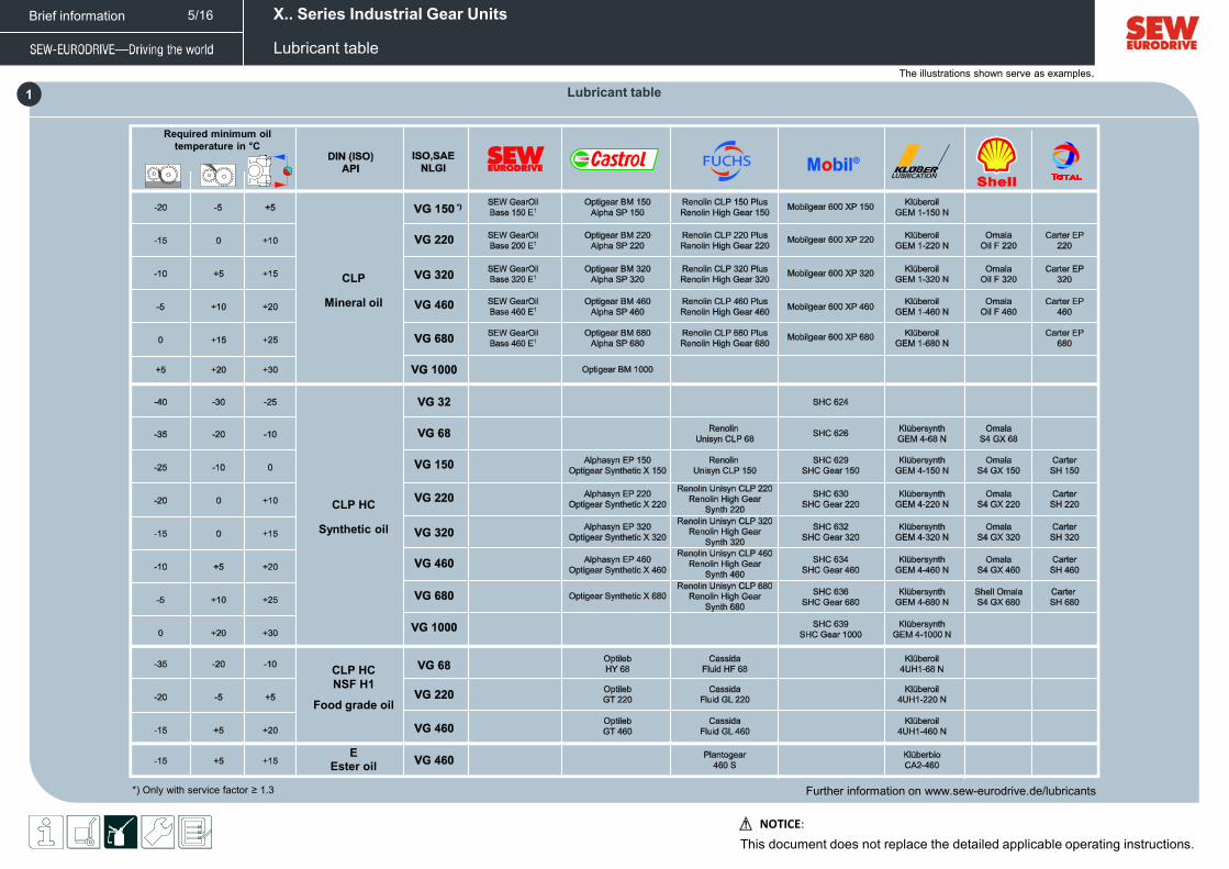
1 Lubricant table
5/16 X.. Series Industrial Gear Units
Lubricant table
Further information on www.sew-eurodrive.de/lubricants *) Only with service factor ≥ 1.3
Required minimum oil temperature in °C
Mineral oil
CLP
Synthetic oil
CLP HC
Food grade oil
CLP HC NSF H1
Ester oil E

The illustrations shown serve as examples.
NOTICE: This document does not replace the detailed applicable operating instructions.
Brief information
Gear unit with fan (option) Gear unit with water cooling cover (option)
6 5 Oil-air cooler for splash lubrication /OAC (option)
1 2 3
4
Standard fan/ axial fan
Advanced fan
Gear unit with cooling water cartridge (option)
[1] Gear unit oil supply [2] Pump with motor [3] Oil pump suction pipe [5] Heat exchanger [8] Temperature switch /TSK [11] Fan motor
X.. Series Industrial Gear Units
Gear unit cooling
6/16
Installing the oil-air cooler
Gear units with pressure lubrication must only be operated with connected pressure switch.
[2] Pump with motor [9] Pressure switch [10] Contamination indicator [11] Fan motor
Oil-air cooler for pressure lubrication /OAP (option)
A: lmax = 2.5 m B: lmax = 1.5 m
Max. 6 bar
a
b
With h2 ≥ h1
Standard: h2 < h1

The illustrations shown serve as examples.
NOTICE: This document does not replace the detailed applicable operating instructions.
Brief information
11
7 8 9
10
X.. Series Industrial Gear Units
Gear unit cooling
7/16
Heat exchanger (OWC/OWP)
Oil-water cooler for splash lubrication /OWC (option)
Design and connection • Observe the requirements on the cooling
media (see operating instructions).
[1] Gear unit oil supply [2] Pump with motor [5] Heat exchanger [6] Cooling water return [7] Cooling water inflow [8] Temperature switch /TSK
Minimum distance to the cooler
Oil-water cooler for pressure lubrication /OWP (option)
Gear units with pressure lubrication must only be operated with connected pressure switch.
Design and connection
[1] Gear unit oil supply [2] Pump with motor [5] Heat exchanger [6] Cooling water return [7] Cooling water inflow [8] Temperature switch /TSK [9] Pressure switch [10] Contamination indicator
Trip points
– STOP drive
– Cooling ON – Cooling OFF
Control of the oil cooling system
X140 – X170 X180 – X320
[1] Gear unit oil supply [4] Oil pump pressure pipe [5] Heat exchanger [6] Cooling water return [7] Cooling water inflow
Temperature switch /TSK Pressure switch /PS
With pressure lubrication
Switch on the pump at least 10 minutes before switching on the main drive.
Controller

The illustrations shown serve as examples.
NOTICE: This document does not replace the detailed applicable operating instructions.
Brief information
8 7
1 3 4 5 2
6
X.. Series Industrial Gear Units
Installing shrink disk X100 – X160
8/16
NOCO
FLUID®
0 mm
Size A (mm) ±0.5 Size A (mm) ± 0.5
X100 37.5 X130 – 140 41
X110 38 X150 42
X120 39 X160 48
a
b
a
b
*Not included in the delivery
*
*Not included in the delivery
*
2.
A
=
=
16
2
34
5

The illustrations shown serve as examples.
NOTICE: This document does not replace the detailed applicable operating instructions.
Brief information X.. Series Industrial Gear Units
Installing shrink disk X170 – X320
1 3 4 5 2
9/16
NOCO
FLUID®
0 mm
8 7 6
Size A (mm) ±0.5 Size A (mm) ±0.5
X170 – 190 37 X270 – 280 49
X200 – 210 38 X290 – 300 49
X220 – 230 39 X310 – 320 60
X240 – 260 48
A
a
b
a
b
*Not included in the delivery
*
*Not included in the delivery
*
2.
=
=
16
2
34
5

The illustrations shown serve as examples.
NOTICE: This document does not replace the detailed applicable operating instructions.
Brief information
7
1
6
Clean coupling and shaft Heat the coupling
Size Screws Tightening torque Nm Strength class
X100 – 110 M16 230 285
X120 – 140 M20 464 555
X150 – 170 M24 798 960
X180 – 220 M30 1597 1910
X230 – 300 M36 2778 3320
X310 – 320 M42 3995 5310
X.. Series Industrial Gear Units
Mounting the flange coupling
10/16
3 4
5
Mount the coupling onto the shaft
Clean the coupling flange Screw on the end ring
Connect the coupling halves Align the shafts Tighten the screws
a
b
a
b
* Only with key
8.8 10.9
Size Screws Tightening torque Nm Strength class
X100 – 110 M16 138 171
X120 – 140 M20 278 333
X150 – 170 M24 478 576
X180 – 220 M30 958 1146
X230 – 300 M36 1666 1992
X310 – 320 M42 2397 3186
8.8 10.9

The illustrations shown serve as examples.
NOTICE: This document does not replace the detailed applicable operating instructions.
Brief information
1 Checks prior to startup
X.. Series Industrial Gear Units
Startup
11/16
Checklist OK
Gear unit has not been damaged during transport.
All transport protection has been removed.
All retaining screws and nuts are tightened to the specified torque.
Correct oil level has been checked by means of oil dipstick or oil level glass.
When using water cooling: Cooling water supply is connected and works properly.
When using oil-air cooling system: Fan motor and pump motor are connected and work properly.
When using fan motor and pump motor: Direction of rotation has been checked and is correct.
When using an oil heater /OH: Oil heater is connected and works properly.
Checklist OK
When using an oil heater /OH: Thermostat is connected and works properly.
When using a temperature sensor PT100: Temperature sensor is connected and works properly.
When using a pressure switch /PS: Pressure switch is connected and works properly.
When using a temperature switch /TSK /NTB: Temperature switch is connected and works properly.
All gear units and electrical mount-on components are grounded.
The shafts are aligned correctly.
Rotating shafts and couplings are equipped with protection covers.
When using gear units with long-term protection: The screw plug has been replaced by a breather.
4 3 Starting up a gear unit with backstop (option)
Starting up the motor pump (option)
Starting up the shaft end pump (option)
2
The direction of rotation is specified as viewed onto the output shaft (LSS). • Clockwise rotation (CW) • Counterclockwise rotation (CCW)
Checklist OK
The pressure switch is connected and ready for operation.
The limit temperature (minimum oil temperature) for gear unit start is observed.
The shaft end pump has been filled with oil before startup.
The shaft end pump provides sufficient oil pressure within 20 seconds.
The minimum speed of the shaft end pump of ≥ 400 min-1 is observed.
Checklist OK
The pressure switch is connected and ready for operation.
The motor pump has been running for 15 min prior to startup.
The oil level has been checked and corrected after motor pump startup.
The limit temperature (minimum oil temperature) for gear unit start is observed.
The permitted direction of rotation is indicated on the housing.
Checklist OK
The direction of rotation of the input shaft (HSS) matches the direction arrow on the input end.
The direction of rotation of the output shaft (LSS) matches the direction arrow on the output end.
5 Inspection intervals
Time interval What to do?
Daily • Check the housing temperature • Check for gear unit noise
Monthly • Check the oil level • Check the gear unit for signs of leakage
After 500 operating hours • First oil change after initial startup
Every 6 months • Check the screw fittings and piping for leakage
Every 3000 operating hours • Check the oil consistency • Refill sealing grease
Depending on the operating conditions At least every 12 months
• Check the breather. • Check alignment of shafts • Check retaining screws • Check condition of oil-water or oil-air cooler • Clean housing • Touch up or renew surface/anti-corrosion coating
Approx. 5000 operating hours* • Change mineral oil
Approx. 10000 operating hours* • Change synthetic oil
*Depending on the operating conditions

The illustrations shown serve as examples.
NOTICE: This document does not replace the detailed applicable operating instructions.
Brief information
1
X.. Series Industrial Gear Units
Possible failures/remedy
12/16
Failure Possible cause Remedy
Unusual noise in the area where the gear unit is mounted
Gear unit mounting has loosened Tighten retaining screws and nuts to the specified torque. Replace the damaged/defective retaining screws or nuts.
Operating temperature too high Too much oil Check the oil level, correct if necessary.
Oil too old Check when the oil was last changed; change the oil, if necessary.
The oil is heavily contaminated Analyze the oil to determine the cause; take measures, if necessary; change the oil.
Ambient temperature too high Protect the gear unit from external heat sources (e.g. provide shade).
Gear units with fan: Air intake opening/gear unit housing contaminated Check air intake openings, clean them if necessary; clean the gear unit housing.
For gear units with built-in cooling: Cooling liquid flow rate too low; cooling liquid temperature too high; deposits in cooling system
Check the cooling liquid flow rate; check the entry temperature of the cooling liquid, clean the cooling system.
Malfunction of the oil-air or oil-water cooling system Observe the separate operating instructions for the oil-water and oil-air cooling system.
Malfunction in the water cooling (water cooling cover, water cooling cartridge) Check the cooling water throughput and the entry temperature of the cooling water, clean the cooling system.
Temperature at bearing points too high
Not enough oil Check the oil level, correct if necessary.
Oil too old Check when the oil was last changed; change the oil, if necessary.
Bearing damaged Check the bearing and replace it if necessary. Contact SEW-EURODRIVE.
Oil leaking at the cover plate, gear unit cover or bearing cover
Seal broken at the cover plate, gear unit cover or bearing cover
Tighten the bolts on the respective cover. Observe the gear unit. Contact SEW-EURODRIVE if oil is still leaking.
Oil leaking from oil seal Too much oil Check the oil level; correct if necessary
Sealing lip of the oil seal turned up Vent the gear unit; monitor the gear unit. Contact SEW-EURODRIVE if oil is still leaking.
Oil seal damaged/worn Check oil seals; replace if necessary.
Oil leaking from gear unit breather Too much oil Check the oil level, correct if necessary.
Drive not installed in proper mounting position Install breather plug correctly and adjust the oil level.
Frequent cold starts (oil foams) and/or high oil level Install oil expansion tank.
24 h service hotline: 0800 7394357

The illustrations shown serve as examples.
NOTICE: This document does not replace the detailed applicable operating instructions.
Brief information
2
X.. Series Industrial Gear Units
Possible failures/remedy
13/16
Failure Possible cause Remedy
Oil leaking - from screw plug - from the oil drain valve
Gasket not tight Retighten screw.
Fittings loosened Retighten the fitting and screw.
Heavy V-belt wear Inadequately aligned belt pulleys Check V-belt pulley alignment and pretension of the belts.
Harmful ambient conditions (e.g. abrasive particles, chemical substances) Protect V-belt drive from environmental influences; sufficient ventilation must be ensured.
V-belt overloaded Replace V-belt if necessary; contact SEW-EURODRIVE.
No oil pump suction Air in the suction line of the oil pump Fill oil into the suction line and the oil pump, vent the pump at the pressure side.
Oil pump defective Contact SEW-EURODRIVE.
Pressure switch not switching Air in the suction line of the oil pump Fill oil into the suction line and the oil pump and vent the pump at the pressure side.
Pressure switch connected incorrectly Check the connection.
Pressure switch defective Replace pressure switch.
Oil pump defective Contact SEW-EURODRIVE.
Malfunction in the oil-water or oil-air cooling system
Malfunction of the oil-water or oil-air cooling system Observe the separate operating instructions for the oil-water or oil-air cooling system.
Gear unit does not reach cold start temperature
Thermostat set incorrectly Check the setting of the thermostat.
Oil heating defective or connected incorrectly Check the oil heater for proper connection and function; replace if necessary.
Heat dissipation too great due to unfavorable climatic conditions Protect the gear unit from cooling off during the warm-up phase.
Operating temperature at backstop too high, no blocking function
Damaged/defective backstop Check the backstop, replace it if necessary.
Contact SEW-EURODRIVE.
24 h service hotline: 0800 7394357

The illustrations shown serve as examples.
NOTICE: This document does not replace the detailed applicable operating instructions.
Brief information X.. Series Industrial Gear Units
Notes
14/16

The illustrations shown serve as examples.
NOTICE: This document does not replace the detailed applicable operating instructions.
Brief information
1. Important Notes 1.1. Safety notes The following basic safety notes must be read carefully to prevent injury to persons and damage to property. The operator must ensure that the basic safety notes are read and adhered to. Ensure that persons responsible for the machinery and its operation as well as persons who work on the unit independently have read through the documentation carefully and understood it. If you are unclear about any of the information in this documentation, or if you require further information, please contact SEW-EURODRIVE. 1.2 General information Never install or start up damaged products. Report any damage to the shipping company immediately. During operation, the gear units can have movable or rotating parts as well as hot surfaces. All work related to transportation, storage, installation, assembly, connection, startup, maintenance and repair may only be carried out by qualified personnel, in strict observance of the comprehensive operating instructions. Removing covers without authorization, improper use, or incorrect installation and operation may result in severe injuries to persons or damage to machinery. 1.3 Target group Any mechanical work may only be performed by adequately qualified personnel. Qualified personnel in this context are persons who are familiar with the setup, mechanical installation, troubleshooting and maintenance for this product. Further, they have training in mechanical engineering, e.g. as a mechanic or mechatronics technician (final examinations must have been passed). Any electronic work may only be performed by adequately electrically skilled persons. Electrically qualified personnel in this context are persons who are familiar with electrical installation, startup, troubleshooting and maintenance for this product. Further, they have training in electrical engineering, e.g. as an electrician or mechatronics technician (final examinations must have been passed). All work in further areas of transportation, storage, operation and waste disposal must only be carried out by persons who are trained appropriately. All qualified personnel must have read and understood the comprehensive operating instructions and wear appropriate protective clothing.
1.4 Designated use The industrial gear units are gear units run by motors for industrial and commercial systems. The units may only be run at the speeds and powers shown in the technical data or on the nameplate. Implementing gear unit loads other than the permitted values or operating the gear units in areas of application other than industrial and commercial systems is only permitted after consultation with SEW-EURODRIVE. Using these products in potentially explosive atmospheres is prohibited, unless specifically designated otherwise. In compliance with the EC Machinery Directive 2006/42/EC, the X.. series industrial gear units are components for installation in machinery and systems. In the scope of the EC directive, you must not take the machinery into operation in the designated fashion until you have established that the end product complies with Machinery Directive 2006/42/EC. 1.5 Other applicable documentation The following publications and documents have to be observed as well: • Operating Instructions: Helical and Bevel-Helical Gear Units X.. Series • Catalog: Helical and Bevel-Helical Gear Units X.. Series • Order documents, e.g. dimension sheet, order confirmation, etc. • If required, the "AC Motors" operating instructions • If required, the operating instructions of the installed options 1.6 Safety symbols on the gear unit The safety symbols on the gear unit must be observed. Refer to the comprehensive operating instructions regarding the meaning of the symbols. 1.7 Transportation/storage Observe the notes in the comprehensive operating instructions regarding transportation, storage, and proper handling. Comply with the requirements for climatic conditions stated in chapter "Storage and transportation conditions". 1.8 Installation/Assembly The units must be installed and assembled according to the regulations and specifications in the corresponding documentation. 1.8 Startup The units must be started up according to the regulations and specifications in the corresponding documentation.
X.. Series Industrial Gear Units
Safety notes
15/16

Brief information