ED50 Electochemical Detector Operator's...
172
ED50 ELECTROCHEMICAL DETECTOR OPERATOR'S MANUAL © 2000 Dionex Corporation Document No. 031673 Revision 01 April 2000
-
Upload
truongtram -
Category
Documents
-
view
223 -
download
0
Transcript of ED50 Electochemical Detector Operator's...

ED50 ELECTROCHEMICAL DETECTOROPERATOR'S MANUAL
© 2000 Dionex Corporation
Document No. 031673Revision 01Ap 0
ril 200Anuta
New Stamp

©2000 by Dionex CorporationAll rights reserved worldwide.Printed in the United States of America.
This publication is protected by federal copyright law. No part of this publication may be copied or distributed, transmitted, transcribed, stored in a retrieval system, or transmitted into any human or computer language, in any form or by any means, electronic, mechanical, magnetic, manual, or otherwise, or disclosed to third parties without the express written permission of Dionex Corporation, 1228 Titan Way, Sunnyvale, California 94088-3603 U.S.A.
DISCLAIMER OF WARRANTY AND LIMITED WARRANTY
THIS PUBLICATION IS PROVIDED “AS IS” WITHOUT WARRANTY OF ANY KIND. DIONEX CORPORATION DOES NOT WARRANT, GUARANTEE, OR MAKE ANY EXPRESS OR IMPLIED REPRESENTATIONS REGARDING THE USE, OR THE RESULTS OF THE USE, OF THIS PUBLICATION IN TERMS OF CORRECTNESS, ACCURACY, RELIABILITY, CURRENTNESS, OR OTHERWISE. FURTHER, DIONEX CORPORATION RESERVES THE RIGHT TO REVISE THIS PUBLICATION AND TO MAKE CHANGES FROM TIME TO TIME IN THE CONTENT HEREINOF WITHOUT OBLIGATION OF DIONEX CORPORATION TO NOTIFY ANY PERSON OR ORGANIZATION OF SUCH REVISION OR CHANGES.
TRADEMARKS
Teflon® and Tefzel® are registered trademarks of E.I. duPont de Nemours & Co.AutoSuppression™, IonSep®, MPIC™, OmniPac®, OnGuard™, SRS®, and Self-Regenerating Suppressor® are trademarks of Dionex Corp.
PRINTING HISTORY
Revision 01, April 2000

Doc. 031673-01 4/2000 i
Contents
1 • Introduction
1.1 Overview . . . . . . . . . . . . . . . . . . . . . . . . . . . . . . . . . . . . . . . . . . . . . . . .1-1
1.2 Modes of Detection . . . . . . . . . . . . . . . . . . . . . . . . . . . . . . . . . . . . . . . .1-2
1.3 About This Manual . . . . . . . . . . . . . . . . . . . . . . . . . . . . . . . . . . . . . . . .1-3
1.3.1 Typefaces . . . . . . . . . . . . . . . . . . . . . . . . . . . . . . . . . . . . . . . . .1-4
1.3.2 Safety Messages and Notes . . . . . . . . . . . . . . . . . . . . . . . . . . .1-5
1.4 Safety Labels . . . . . . . . . . . . . . . . . . . . . . . . . . . . . . . . . . . . . . . . . . . . .1-6
2 • Description
2.1 Front Control Panel . . . . . . . . . . . . . . . . . . . . . . . . . . . . . . . . . . . . . . . .2-1
2.1.1 Control Panel Display . . . . . . . . . . . . . . . . . . . . . . . . . . . . . . .2-1
2.1.2 Control Panel Keypad . . . . . . . . . . . . . . . . . . . . . . . . . . . . . . .2-2
2.2 Rear Panel . . . . . . . . . . . . . . . . . . . . . . . . . . . . . . . . . . . . . . . . . . . . . . .2-6
2.3 Electronics Chassis . . . . . . . . . . . . . . . . . . . . . . . . . . . . . . . . . . . . . . . .2-7
2.3.1 Connectors . . . . . . . . . . . . . . . . . . . . . . . . . . . . . . . . . . . . . . . .2-8
2.3.2 Cards . . . . . . . . . . . . . . . . . . . . . . . . . . . . . . . . . . . . . . . . . . . . .2-9
2.4 Conductivity Cell . . . . . . . . . . . . . . . . . . . . . . . . . . . . . . . . . . . . . . . . .2-11
2.4.1 DS3 Detection Stabilizer . . . . . . . . . . . . . . . . . . . . . . . . . . . .2-12
2.4.2 Shielded Cell . . . . . . . . . . . . . . . . . . . . . . . . . . . . . . . . . . . . .2-13
2.5 Amperometry Cell . . . . . . . . . . . . . . . . . . . . . . . . . . . . . . . . . . . . . . . .2-14
2.5.1 Combination pH–Ag/AgCl Reference Electrode . . . . . . . . . .2-15
Contents
Doc. 031673-01 4/2000 ii
2.6 Functional Description . . . . . . . . . . . . . . . . . . . . . . . . . . . . . . . . . . . .2-16
2.6.1 Operating and Control Modes . . . . . . . . . . . . . . . . . . . . . . . .2-16
2.6.2 Local and Remote Modes . . . . . . . . . . . . . . . . . . . . . . . . . . . .2-17
2.6.3 Method Control . . . . . . . . . . . . . . . . . . . . . . . . . . . . . . . . . . .2-18
2.6.4 TTL Input Control . . . . . . . . . . . . . . . . . . . . . . . . . . . . . . . . .2-19
3 • Operation and Maintenance
3.1 Getting Ready to Run . . . . . . . . . . . . . . . . . . . . . . . . . . . . . . . . . . . . . .3-1
3.2 Initial Screens . . . . . . . . . . . . . . . . . . . . . . . . . . . . . . . . . . . . . . . . . . . .3-3
3.3 Selecting the Control Mode . . . . . . . . . . . . . . . . . . . . . . . . . . . . . . . . . .3-4
3.4 Running Under Direct Control (Local Mode) . . . . . . . . . . . . . . . . . . . .3-5
3.5 Running Under Method Control (Local Mode) . . . . . . . . . . . . . . . . . . .3-5
3.5.1 Running a Method . . . . . . . . . . . . . . . . . . . . . . . . . . . . . . . . . .3-5
3.5.2 Changing the Running Method . . . . . . . . . . . . . . . . . . . . . . . .3-6
3.5.3 Changing a Method-Controlled Parameter . . . . . . . . . . . . . . . .3-6
3.5.4 Creating a New Method . . . . . . . . . . . . . . . . . . . . . . . . . . . . . .3-7
3.5.5 Editing an Existing Method . . . . . . . . . . . . . . . . . . . . . . . . . . .3-8
3.6 Optimizing Temperature Compensation . . . . . . . . . . . . . . . . . . . . . . .3-10
3.6.1 With a DS3 and Conductivity Cell . . . . . . . . . . . . . . . . . . . . .3-10
3.6.2 With a Shielded Conductivity Cell . . . . . . . . . . . . . . . . . . . . .3-11
3.7 Waveforms . . . . . . . . . . . . . . . . . . . . . . . . . . . . . . . . . . . . . . . . . . . . .3-12
3.8 Voltammetry . . . . . . . . . . . . . . . . . . . . . . . . . . . . . . . . . . . . . . . . . . . .3-13
3.8.1 Non-Dionex Voltammetry Cells . . . . . . . . . . . . . . . . . . . . . .3-13
3.8.2 Recorder Connections . . . . . . . . . . . . . . . . . . . . . . . . . . . . . .3-15
Contents
Doc. 031673-01 4/2000 iii
3.8.3 Programming the Voltammetry Waveform . . . . . . . . . . . . . .3-16
3.8.4 Running the Waveform . . . . . . . . . . . . . . . . . . . . . . . . . . . . .3-17
3.9 Routine Maintenance . . . . . . . . . . . . . . . . . . . . . . . . . . . . . . . . . . . . . .3-18
3.10 Shutdown . . . . . . . . . . . . . . . . . . . . . . . . . . . . . . . . . . . . . . . . . . . . . . .3-19
4 • Troubleshooting
4.1 No Detector Response . . . . . . . . . . . . . . . . . . . . . . . . . . . . . . . . . . . . . .4-1
4.2 Low Detector Output . . . . . . . . . . . . . . . . . . . . . . . . . . . . . . . . . . . . . . .4-2
4.3 High Detector Output . . . . . . . . . . . . . . . . . . . . . . . . . . . . . . . . . . . . . .4-2
4.4 Noisy or Drifting Baseline . . . . . . . . . . . . . . . . . . . . . . . . . . . . . . . . . . .4-3
4.5 Tailing Peaks . . . . . . . . . . . . . . . . . . . . . . . . . . . . . . . . . . . . . . . . . . . . .4-4
4.6 Amperometry Cell pH Readout Always 7.0 . . . . . . . . . . . . . . . . . . . . .4-4
4.7 Cannot Set Amperometry Cell pH Readout to 7.0 . . . . . . . . . . . . . . . .4-4
4.8 No Amperometry Cell pH Readout . . . . . . . . . . . . . . . . . . . . . . . . . . . .4-5
4.9 Discolored pH Reference Electrode . . . . . . . . . . . . . . . . . . . . . . . . . . .4-5
4.10 Leaking pH Reference Electrode . . . . . . . . . . . . . . . . . . . . . . . . . . . . . .4-5
4.11 Shift in Ag/AgCl Reference Potential . . . . . . . . . . . . . . . . . . . . . . . . . .4-6
4.12 Liquid Leaks from the DS3 . . . . . . . . . . . . . . . . . . . . . . . . . . . . . . . . . .4-7
4.13 DS3 Temperature Inaccurate . . . . . . . . . . . . . . . . . . . . . . . . . . . . . . . .4-10
4.14 Conductivity Inaccurate . . . . . . . . . . . . . . . . . . . . . . . . . . . . . . . . . . . .4-11
4.15 Faulty DX-LAN Communication . . . . . . . . . . . . . . . . . . . . . . . . . . . .4-12
4.16 Diagnostics . . . . . . . . . . . . . . . . . . . . . . . . . . . . . . . . . . . . . . . . . . . . .4-12

Contents
Doc. 031673-01 4/2000 iv
5 • Service
5.1 Eliminating Liquid Leaks . . . . . . . . . . . . . . . . . . . . . . . . . . . . . . . . . . .5-2
5.2 Removing Trapped Air from the Cell . . . . . . . . . . . . . . . . . . . . . . . . . .5-2
5.3 Replacing the DS3 Cell . . . . . . . . . . . . . . . . . . . . . . . . . . . . . . . . . . . . .5-2
5.4 Calibrating the Cell . . . . . . . . . . . . . . . . . . . . . . . . . . . . . . . . . . . . . . . .5-4
5.5 Polishing the Working Electrodes . . . . . . . . . . . . . . . . . . . . . . . . . . . . .5-5
5.5.1 Polishing with a Pencil Eraser (Gold Electrodes Only) . . . . . .5-5
5.5.2 Polishing with Polishing Compounds . . . . . . . . . . . . . . . . . . .5-6
5.6 Replacing the pH Reference Electrode O-Ring . . . . . . . . . . . . . . . . . . .5-8
5.7 Replacing the Main Power Fuses . . . . . . . . . . . . . . . . . . . . . . . . . . . . .5-9
A • Specifications
A.1 Physical . . . . . . . . . . . . . . . . . . . . . . . . . . . . . . . . . . . . . . . . . . . . . . . . A-1
A.2 Environmental . . . . . . . . . . . . . . . . . . . . . . . . . . . . . . . . . . . . . . . . . . . A-1
A.3 Electrical . . . . . . . . . . . . . . . . . . . . . . . . . . . . . . . . . . . . . . . . . . . . . . . A-1
A.4 Display and Keypad . . . . . . . . . . . . . . . . . . . . . . . . . . . . . . . . . . . . . . A-1
A.5 Detector . . . . . . . . . . . . . . . . . . . . . . . . . . . . . . . . . . . . . . . . . . . . . . . . A-2
A.6 Conductivity Cell . . . . . . . . . . . . . . . . . . . . . . . . . . . . . . . . . . . . . . . . . A-2
A.7 Amperometry Cell . . . . . . . . . . . . . . . . . . . . . . . . . . . . . . . . . . . . . . . . A-3
A.8 SRS Power Supply . . . . . . . . . . . . . . . . . . . . . . . . . . . . . . . . . . . . . . . A-3
A.9 DS3 Detection Stabilizer . . . . . . . . . . . . . . . . . . . . . . . . . . . . . . . . . . . A-3

Contents
Doc. 031673-01 4/2000 v
B • Installation
B.1 Facility Requirements . . . . . . . . . . . . . . . . . . . . . . . . . . . . . . . . . . . . . B-1
B.2 Installation . . . . . . . . . . . . . . . . . . . . . . . . . . . . . . . . . . . . . . . . . . . . . . B-2
B.2.1 Power Connection . . . . . . . . . . . . . . . . . . . . . . . . . . . . . . . . . . B-2
B.2.2 DX-LAN Interface: 10BASE-T Connections (Optional) . . . . B-4
B.2.3 DX-LAN Interface: BNC Connections (Optional) . . . . . . . . . B-7
B.2.4 DS3 Detection Stabilizer Installation . . . . . . . . . . . . . . . . . . B-10
B.2.5 Shielded Conductivity Cell Installation . . . . . . . . . . . . . . . . B-10
B.2.6 DS3 or Shielded Cell Plumbing . . . . . . . . . . . . . . . . . . . . . . B-10
B.2.7 Amperometry Cell Installation . . . . . . . . . . . . . . . . . . . . . . . B-18
B.2.8 Recorder/Diagnostic Connection . . . . . . . . . . . . . . . . . . . . . B-21
B.3 Automatic SRS Power Control . . . . . . . . . . . . . . . . . . . . . . . . . . . . . B-22
C • User Interface
C.1 Operational Screens . . . . . . . . . . . . . . . . . . . . . . . . . . . . . . . . . . . . . . . C-2
C.1.1 Menu of Screens—Conductivity . . . . . . . . . . . . . . . . . . . . . . . C-2
C.1.2 Main Screen—Conductivity . . . . . . . . . . . . . . . . . . . . . . . . . . C-3
C.1.3 Detail Screen—Conductivity . . . . . . . . . . . . . . . . . . . . . . . . . C-4
C.1.4 Method—Conductivity . . . . . . . . . . . . . . . . . . . . . . . . . . . . . . C-5
C.1.5 Menu of Screens—Integrated Amperometry . . . . . . . . . . . . . C-7
C.1.6 Main Screen—Integrated Amperometry . . . . . . . . . . . . . . . . . C-8
C.1.7 Detail Screen—Integrated Amperometry . . . . . . . . . . . . . . . . C-9
C.1.8 Method—Integrated Amperometry. . . . . . . . . . . . . . . . . . . . C-10
C.1.9 Waveform—Integrated Amperometry . . . . . . . . . . . . . . . . . C-12
ED50 Electrochemical Detector
vi Doc. 031673-01 4/2000
C.1.10 Menu of Screens—DC Amperometry . . . . . . . . . . . . . . . . . .C-13
C.1.11 Main Screen—DC Amperometry. . . . . . . . . . . . . . . . . . . . . .C-14
C.1.12 Detail Screen—DC Amperometry . . . . . . . . . . . . . . . . . . . . .C-15
C.1.13 Method—DC Amperometry. . . . . . . . . . . . . . . . . . . . . . . . . .C-16
C.1.14 Menu of Screens—Voltammetry . . . . . . . . . . . . . . . . . . . . . .C-18
C.1.15 Main Screen—Voltammetry . . . . . . . . . . . . . . . . . . . . . . . . .C-19
C.1.16 Detail Screen — Voltammetry . . . . . . . . . . . . . . . . . . . . . . . .C-20
C.1.17 Waveform—Voltammetry . . . . . . . . . . . . . . . . . . . . . . . . . . .C-21
C.1.18 Module Setup . . . . . . . . . . . . . . . . . . . . . . . . . . . . . . . . . . . . .C-22
C.1.19 Analog Out Setup . . . . . . . . . . . . . . . . . . . . . . . . . . . . . . . . . .C-23
C.1.20 Time Function In . . . . . . . . . . . . . . . . . . . . . . . . . . . . . . . . . .C-24
C.2 Diagnostic Screens . . . . . . . . . . . . . . . . . . . . . . . . . . . . . . . . . . . . . . .C-25
C.2.1 Diagnostic Menu . . . . . . . . . . . . . . . . . . . . . . . . . . . . . . . . . .C-25
C.2.2 Power-Up Screen . . . . . . . . . . . . . . . . . . . . . . . . . . . . . . . . . .C-26
C.2.3 Elapsed Time . . . . . . . . . . . . . . . . . . . . . . . . . . . . . . . . . . . . .C-27
C.2.4 Analog Status . . . . . . . . . . . . . . . . . . . . . . . . . . . . . . . . . . . . .C-28
C.2.5 DX-LAN Status . . . . . . . . . . . . . . . . . . . . . . . . . . . . . . . . . . .C-29
C.2.6 Keyboard Test . . . . . . . . . . . . . . . . . . . . . . . . . . . . . . . . . . . .C-31
C.2.7 Diagnostic Tests . . . . . . . . . . . . . . . . . . . . . . . . . . . . . . . . . . .C-32
C.2.8 Leak Sensor Calibration and Status . . . . . . . . . . . . . . . . . . . .C-35
C.2.9 Signal Statistics . . . . . . . . . . . . . . . . . . . . . . . . . . . . . . . . . . .C-36
C.2.10 Calibrate Conductivity Cell . . . . . . . . . . . . . . . . . . . . . . . . . .C-37
C.2.11 pH Calibration . . . . . . . . . . . . . . . . . . . . . . . . . . . . . . . . . . . .C-38

Contents
Doc. 031673-01 4/2000 vii
D • TTL and Relay Control
D.1 TTL and Relay Connections . . . . . . . . . . . . . . . . . . . . . . . . . . . . . . . . D-2
D.2 TTL and Relay Output Operation . . . . . . . . . . . . . . . . . . . . . . . . . . . . D-3
D.3 TTL Input Operation . . . . . . . . . . . . . . . . . . . . . . . . . . . . . . . . . . . . . . D-4
D.3.1 TTL Input Functions . . . . . . . . . . . . . . . . . . . . . . . . . . . . . . . . D-4
D.3.2 TTL Input Signal Modes . . . . . . . . . . . . . . . . . . . . . . . . . . . . . D-5
E • Signal Processor Functions
F • Connector Pinouts
F.1 Recorder/Diagnostic Signal Pinouts . . . . . . . . . . . . . . . . . . . . . . . . . . F-1
F.1.1 Signal Electrical Parameters . . . . . . . . . . . . . . . . . . . . . . . . . . F-2
F.2 TTL/Relay Pinouts . . . . . . . . . . . . . . . . . . . . . . . . . . . . . . . . . . . . . . . F-5
F.3 DS3 Connector Pinouts—SCR . . . . . . . . . . . . . . . . . . . . . . . . . . . . . . F-6
F.4 SRS Connector Pinouts—SCR . . . . . . . . . . . . . . . . . . . . . . . . . . . . . . F-7
5.8 Amperometry Cell Connector Pinouts—SP . . . . . . . . . . . . . . . . . . . . F-8
F.5 Conductivity Cell Connector Pinouts—SP . . . . . . . . . . . . . . . . . . . . . F-8
G • Reordering Information
Index

ED50 Electrochemical Detector
viii Doc. 031673-01 4/2000

Doc. 031673-01 4/2000 1-1
1 • Introduction
1.1 OverviewThe ED50 Electrochemical Detector measures current resulting from the application of potential (voltage) across electrodes in flow-through cells. Depending on the method by which the potential is applied and the current measured, several different properties of the flowing solution can be determined. These measurements help answer the major questions analytical chemists ask: What's in it, and how much is there?
Of course, other detectors are used in high performance liquid chromatography (HPLC). The UV-visible absorbance detector dominates all other forms of detection. Sensitivity is excellent for many analytes, especially aromatic species, and transparent mobile phases are readily available. However, there are numerous analytes that have very poor absorbance and are not detected with sufficient sensitivity by UV absorbance. Most of these nonchromophoric molecules are aliphatic organic molecules and inorganic ions. Low wavelength UV detection can be used, but at a loss in selectivity. Refractive index detection can also be used. However, maintaining a stable baseline can be difficult, and RI detection is less sensitive and substantially less selective than UV detection.
Fortunately, a wide variety of nonchromophoric molecules can be detected with good or excellent sensitivity by one of several forms of electrochemical detection. These molecules include carboxylic, sulfonic and phosphonic acids; alcohols, glycols, aldehydes, and carbohydrates; primary, secondary, tertiary, and quaternary amines; sulfates, sulfoxides, thiols, sulfides, and mercaptans; and inorganic anions and cations. In addition, when compared to UV absorbance detection, electrochemical detection provides substantial improvements in sensitivity and selectivity for amine and hydroxy-substituted aromatics such as catecholamines.
Several forms of electrochemical detection have become popular for certain HPLC applications. Conductivity is the workhorse detection method in ion chromatography, just as UV detection is for HPLC. DC amperometry is the preferred method for neurochemical analyses. Pulsed amperometry is now established as the superior detection method for carbohydrates. For most of the numerous analytes listed in the previous paragraph, detection by UV-visible

ED50 Electrochemical Detector
1-2 Doc. 031673-01 4/2000
absorbance is poor, while one of the three main techniques of electrochemical detection provided by the ED50 provides superior sensitivity and selectivity.
Electrochemical detection is not a substitute for UV-visible absorbance detection, but is an important complement. A liquid chromatograph equipped with both a Dionex absorbance detector and an electrochemical detector is a versatile and powerful analytical instrument.
The ED50 can be controlled locally, from the front panel, or remotely (via the Dionex DX-LAN™ interface) from a host computer running PeakNet 6, Release 6.1 (or later) software.
1.2 Modes of DetectionThe ED50 provides the three major forms of electrochemical detection: conductivity, DC amperometry, and integrated amperometry. Pulsed amperometry is a form of integrated amperometry.
Conductivity detection is based on the measurement of the magnitude of electrical current carried by dissolved ions in an electric field.
DC Amperometric detection is based on the measurement of current resulting from oxidation or reduction (electrolysis) of analyte molecules at the surface of an electrode.
Integrated and pulsed amperometric detection are similar to DC Amperometry in that molecules are oxidized or reduced at the surface of an electrode. However, current is measured by integration during a portion of a repeating potential vs. time waveform.
In addition, the voltammetry mode is used to determine potentials used in DC and integrated amperometry.

1 • Introduction
Doc. 031673-01 4/2000 1-3
1.3 About This Manual
Chapter 1Introduction
Provides a brief overview of the ED50 Electrochemical Detector. Explains the meaning of safety messages and icons in the manual and safety labels on the detector.
Chapter 2Description
Describes physical aspects of the ED50, including the front panel controls, electronics, and flow cell. Explains the detector operating modes.
Chapter 3Operation and
Maintenance
Describes operating features and how to create, edit, and run methods from the ED50 front panel. Lists routine preventive maintenance requirements.
Chapter 4Troubleshooting
Lists possible causes of problems and step-by-step procedures to isolate and eliminate them.
Chapter 5Service
Contains step-by-step instructions for routine service and parts replacement procedures.
Appendix ASpecifications
Lists the ED50 specifications and installation site requirements.
Appendix BInstallation
Describes how to install the ED50.
Appendix CDisplay Screens
Illustrates and describes all operating and diagnostic screens that can be displayed on the front panel.
Appendix DTTL and Relay
Control
Describes the ED50 TTL and Relay control functions. Provides installation instructions.
Appendix ESignal Processor
Functions
Lists the functions of the Signal Processor (SP) card.
Appendix FConnector Pinouts
Describes the pinouts for all ED50 connectors.
Appendix GReordering
Information
Lists spare parts for the detector.
ED50 Electrochemical Detector
1-4 Doc. 031673-01 4/2000
1.3.1 Typefaces Capitalized bold type indicates a front panel button:
Press Enter to begin running the method.
Uppercase bold type indicates the name of a menu, the name of a screen, or an on-screen entry:
Display the METHOD screen.
Move the cursor to the EDIT field.

1 • Introduction
Doc. 031673-01 4/2000 1-5
1.3.2 Safety Messages and NotesThis manual contains warnings and precautionary statements that can prevent personal injury and/or damage to the ED50 when properly followed. Safety messages appear in bold type and are accompanied by icons, as shown below.
Informational messages also appear throughout this manual. These are labeled NOTE and are in bold type:
NOTE NOTES call attention to certain information. They alertyou to an unexpected result of an action, suggest how tooptimize instrument performance, etc.
Indicates an imminently hazardous situation which, if notavoided, will result in death or serious injury.
Indicates a potentially hazardous situation which, if notavoided, could result in death or serious injury.
Indicates a potentially hazardous situation which, if notavoided, may result in minor or moderate injury.
Indicates that the function or process of the instrument may beimpaired. Operation does not constitute a hazard.

ED50 Electrochemical Detector
1-6 Doc. 031673-01 4/2000
1.4 Safety LabelsThe CE and GS safety label on the ED50 attests to compliance with the following European, EMC, and safety requirements: Council Directives 73/23/EEC and 89/336/EEC, EN 61010-1:1993 (safety), EN 50082-1:1992 (susceptibility), and EN 55011:1991 (emissions).
The symbols below appear on the ED50 or on ED50 labels.
Alternating current
Protective conductor terminal (earth ground)
Power supply is on
Power supply is off
˜

Doc. 031673-01 4/2000 2-1
2 • Description
2.1 Front Control PanelThe control panel on the front door of the ED50 contains the liquid crystal display (LCD), the membrane keypad, and the actuator for the main power switch. The electronics chassis, described in Section 2.3, is located behind the front door.
Power Switches
The main power switch is on a bulkhead inside the electronics chassis (in the front, left-hand corner). The actuator for the power switch is on the front door, below the control panel (see Figure 2-1). The actuator functions only when the front door is fully closed. When the door is open, press the main power switch to turn the ED50 on and off.
2.1.1 Control Panel DisplayThe LCD, also called the screen, displays ED50 status and operating information. Fields on the screen that are in reverse video (blue letters on a white background) can be edited, while normal video fields are simply informational displays.
To adjust the screen contrast, rotate the knurled knob in the recess below the Help and Menu buttons (see Figure 2-1).
To adjust the brightness of the screen backlight, select a different DISPLAY PANEL BACKLIGHT option on the MODULE SETUP screen (see Section C.1.18).

ED50 Electrochemical Detector
2-2 Doc. 031673-01 4/2000
2.1.2 Control Panel KeypadUse the keypad to directly control ED50 operation, as well as to create and modify programmed series of timed events, called methods. In summary:
Press Menu to display a list of available screens.
In the screens, only fields shown in reverse video can be edited. Other fields only display information.
To edit a field, use the four directional arrow buttons to position the cursor in the reverse video fields. Use the numeric buttons to enter variable values.
Figure 2-1. ED50 Front Panel
! "
#
M AIN SCREENDETAIL SCREENM ETHO D- - -
E
M ain Pow erSw itch A ctuator
Tab(for openingthe door)
Knob(for adjustingthe contrast)

2 • Description
Doc. 031673-01 4/2000 2-3
Use the Select ∇ and Select ∆ buttons to choose between predetermined options. Pressing a Select button increases (or decreases) a numeric value by one; holding down a Select button increases (or decreases) a numeric value continuously.
Press Enter or a cursor arrow button to execute the selected value.
A high-pitched beep sounds when a button is pressed. When an error occurs, this beep is lower in frequency. The beeps can be disabled from the MODULE SETUP screen (see Section C.1.18).
Button Function
Offset Returns the analog (recorder) output to a predetermined baseline and zeros the display. The resultant value of the offset required is displayed on the DETAIL screen. This function can be programmed in a method.
Mark Sends a 10% positive event mark to the analog (recorder) output. A mark is typically used to indicate a sample injection. This function can be programmed in a method.
Insert Inserts a new step into a method.
To add a new step, move the cursor to the TIME field and press Insert. A new blank step appears below the cursor position. After entering a time value, press Enter or a cursor arrow button. Insert steps in any order and they will be automatically reorganized in the correct chronological order.
Delete Removes the value from the current entry field. To restore the previous value, move the cursor from the field before entering a new value.
Pressing Delete when the cursor is in a step entry field on the METHOD screen “blanks” the step parameter value. Moving the cursor to another field does not restore the previous value; instead, the step remains blank, indicating no change from the previous step.
To delete an entire method step:
1. Position the cursor in the method’s TIME field and press Delete. The time is removed and the help line prompts you to press Delete again to delete the step.
2. Press Delete again. Or, to restore the original time and step parameters, press any button except Delete.
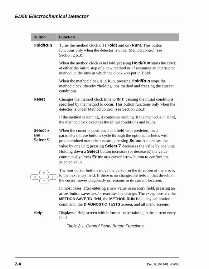
Table 2-1. Control Panel Button Functions
ED50 Electrochemical Detector
2-4 Doc. 031673-01 4/2000
Hold/Run Turns the method clock off (Hold) and on (Run). This button functions only when the detector is under Method control (see Section 2.6.3).
When the method clock is in Hold, pressing Hold/Run starts the clock at either the initial step of a new method or, if resuming an interrupted method, at the time at which the clock was put in Hold.
When the method clock is in Run, pressing Hold/Run stops the method clock, thereby “holding” the method and freezing the current conditions.
Reset Changes the method clock time to INIT, causing the initial conditions specified by the method to occur. This button functions only when the detector is under Method control (see Section 2.6.3).
If the method is running, it continues running. If the method is in Hold, the method clock executes the initial conditions and holds.
Select ∆ and Select ∇
When the cursor is positioned at a field with predetermined parameters, these buttons cycle through the options. In fields with predetermined numerical values, pressing Select ∆ increases the value by one unit; pressing Select ∇ decreases the value by one unit. Holding down a Select button increases (or decreases) the value continuously. Press Enter or a cursor arrow button to confirm the selected value.
The four cursor buttons move the cursor, in the direction of the arrow, to the next entry field. If there is no changeable field in that direction, the cursor moves diagonally or remains in its current location.
In most cases, after entering a new value in an entry field, pressing an arrow button saves and/or executes the change. The exceptions are the METHOD SAVE TO field, the METHOD RUN field, any calibration command, the DIAGNOSTIC TESTS screen, and all menu screens.
Help Displays a Help screen with information pertaining to the current entry field.
Button Function
Table 2-1. Control Panel Button Functions

2 • Description
Doc. 031673-01 4/2000 2-5
Menu Displays one of two menus, depending on the current screen:
From an operational screen, pressing Menu displays the MENU of SCREENS.
From a diagnostic screen, pressing Menu once returns you to the DIAGNOSTIC MENU; pressing Menu again returns you to the MENU of SCREENS.
Numeric Buttons
Enters numeric values into the current entry field. The numeric buttons are 0 through 9 and the decimal.
From a menu screen, pressing a numeric button opens the corresponding screen.
Enter Saves and/or executes changes made in entry fields. If a menu screen is displayed, pressing Enter opens the highlighted screen.
Button Function
Table 2-1. Control Panel Button Functions

ED50 Electrochemical Detector
2-6 Doc. 031673-01 4/2000
2.2 Rear PanelThe ED50 rear panel (see Figure B-1) contains fuses, connectors for line power, and a connection for the optional DX-LAN interface.
Power Entry
The power entry, fusing, and EMI filter are mounted on the rear of the 45 W power supply module. The power entry is socketed for a modular power cord (IEC 320 C13). The detector requires a grounded, single-phase power source. The detector may be operated from 85 to 270 Vac, 47 to 63 Hz power. The input power is 50 W maximum. The line voltage is automatically selected and requires no adjustments.
Fuses
The ED50 uses two 3.15 A fast-blow fuses (IEC 127 type 1, P/N 954745). See Section 5.7 for instructions on replacing the fuses.
DX-LAN Connection (Optional)
When you order the DX-LAN network, a DX-LAN connector is factory-installed in the upper left corner of the ED50 rear panel (see Figure B-1 in Appendix B). See Appendix B for DX-LAN interface installation instructions.
External Connection Access
Connections to the front of the electronics chassis, such as TTL and relay cables, are usually routed to the back of the detector through the cable chase in the bottom of the electronics chassis. They may also be passed through slots at the front of the detector. Cables exit the ED50 through an opening in the rear panel (see Figure B-1).
SHOCK HAZARD—To avoid electrical shock, a groundedreceptacle must be used. Do not operate or connect to ACpower mains without an earthed ground connection.
For continued protection against risk of fire or shock, alwaysreplace with fuses of the same type and rating.

2 • Description
Doc. 031673-01 4/2000 2-7
2.3 Electronics ChassisThe electronics chassis is located immediately behind the front door of the ED50. The chassis contains several electronics cards (printed circuit boards) that are used to control the ED50. Various connectors on the cards allow communication between the ED50 and other [system name] modules and accessories. Figure 2-2 identifies the cards and their connectors.
Do not remove any of the electronics cards from the detector.There are no user-serviceable components on the cards. Ifservicing is required, it must be performed by qualifiedpersonnel following appropriate electrostatic discharge (ESD)handling procedures must be followed.
Figure 2-2. ED50 Electronics Chassis Components
!"!##$ "%"$

ED50 Electrochemical Detector
2-8 Doc. 031673-01 4/2000
2.3.1 ConnectorsThere are electrical connections to three cards in the ED50 electronics chassis.
Amperometry Cell—Provides all connections to the amperometry cell.
Conductivity Cell—Provides all connections to the conductivity cell, including temperature compensation.
Analog Output—Provides for easy attachment of hook-up wire leads, using a small screwdriver. This connector is typically used with a recorder/integrator or diagnostic instruments. For the connector pinout descriptions, see Section F.1 in Appendix F.
SRS—Provides for all connections, including power, to the Self-Regenerating Suppressor® (SRS®).
DS3—Provides for all connections, including power, to the DS3 Detection Stabilizer.
Relay—Provides 2 relay output connector plugs for easy attachment of hook-up wire leads, using a small screwdriver.
TTL Output—Provides 2 TTL output connector plugs for connecting the ED50 to another TTL-compatible device.
TTL Input—Provides 4 TTL input connector plugs for control of the detector from another TTL-compatible device. These connectors are identified as TTL1 through TTL4 on the TIME FUNCTION IN screen.
60-pin ribbon connector—Provides the connector plug for the 60-pin ribbon cable to the ED50 front panel (display and keypad).
2 • Description
Doc. 031673-01 4/2000 2-9
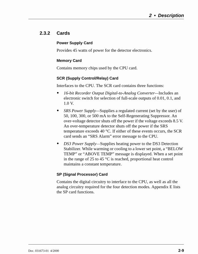
2.3.2 Cards
Power Supply Card
Provides 45 watts of power for the detector electronics.
Memory Card
Contains memory chips used by the CPU card.
SCR (Supply Control/Relay) Card
Interfaces to the CPU. The SCR card contains three functions:
16-bit Recorder Output Digital-to-Analog Converter—Includes an electronic switch for selection of full-scale outputs of 0.01, 0.1, and 1.0 V.
SRS Power Supply—Supplies a regulated current (set by the user) of 50, 100, 300, or 500 mA to the Self-Regenerating Suppressor. An over-voltage detector shuts off the power if the voltage exceeds 8.5 V. An over-temperature detector shuts off the power if the SRS temperature exceeds 40 °C. If either of these events occurs, the SCR card sends an “SRS Alarm” error message to the CPU.
DS3 Power Supply—Supplies heating power to the DS3 Detection Stabilizer. While warming or cooling to a lower set point, a “BELOW TEMP” or “ABOVE TEMP” message is displayed. When a set point in the range of 25 to 45 °C is reached, proportional heat control maintains a constant temperature.
SP (Signal Processor) Card
Contains the digital circuitry to interface to the CPU, as well as all the analog circuitry required for the four detection modes. Appendix E lists the SP card functions.

ED50 Electrochemical Detector
2-10 Doc. 031673-01 4/2000
Relay/DX-LAN and CPU Cards
The ED50 control Moduleware and BIOS reside on the CPU logic and Relay I/O cards.
The CPU card provides control and monitoring of the other modules. A 60-pin ribbon cable assembly links the logic to the ED50 front panel display and keypad.
The Relay I/O card provides two isolated low voltage relay outputs, two TTL outputs, and four TTL inputs.
The cards are in slot 5 of the card cage. The Relay card is a half-card which rides piggyback on the CPU card and extends over the front of slot 4.
The Relay I/O card is short enough to allow a detector interface card (P/N 044196) to be mounted behind it in slot 4. The interface card is required for communication between the ED50 and PeakNet Software.
Below the I/O connections is a multicolor LED that indicates the state of the power supply.
A green LED indicates normal operation.
A red or yellow LED indicates a fault. If a fault occurs, the ED50 enters its diagnostic state and no other control is permitted until the fault is corrected. Turn off the power to the ED50 for a few seconds and then turn it on again. If the power fault remains, contact Dionex.

2 • Description
Doc. 031673-01 4/2000 2-11
2.4 Conductivity CellThe flow-through conductivity cell has an active volume of about 1.0 µL. Two 316 stainless steel electrodes are permanently sealed into the PEEK cell body. The cell constant has a nominal value of 160 cm-1 and is calibrated electronically. A sensor located slightly downstream from the electrodes senses the temperature of liquid passing through the cell. The measured value is used to provide temperature compensation.
The advanced geometry of the cell provides several benefits:
Excellent accuracy and linearity over the working range
Efficient sweepout and low volume for low dispersion
Reduced sensitivity to electrode surface conditions
Low electrode mass
Effective temperature compensation
You can order the conductivity cell installed in a DS3 Detection Stabilizer (P/N 044130) for temperature control, or installed in an electrical shield (P/N 044132) which provides no temperature control. Because the DS3 maintains a constant temperature, thus reducing the effects of variations in laboratory temperature, the DS3 is recommended for conductivity detection.
Temperature Control and Compensation
Temperature directly affects the conductivity of a solution. As conductivity increases, the effect of temperature changes becomes more pronounced. For example, building temperature control systems can cause a regular oscillation in the baseline. This, in turn, can affect the reproducibility of an analysis.
In ion chromatography, suppressing eluent conductivity minimizes the effect of temperature variation. Temperature compensation further improves baseline stability. When the conductivity cell is housed in a DS3 Detection Stabilizer, the DS3 enhances the ability of these techniques to reduce temperature effects below the detection limit.
Temperature compensation also ensures that there will be no major change in the baseline or peak heights, should it be necessary to change the DS3 operating set point. Readings will be normalized to 25 °C.

ED50 Electrochemical Detector
2-12 Doc. 031673-01 4/2000
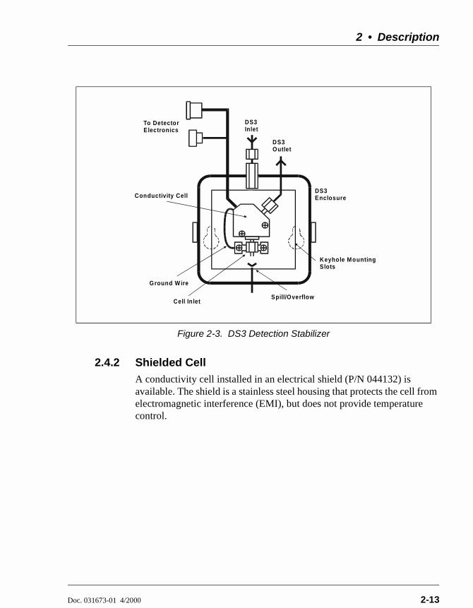
2.4.1 DS3 Detection StabilizerThe DS3 is a temperature-controlled chamber consisting of a cast aluminum base and cover enclosed in insulating foam. The chamber houses both the conductivity cell and the eluent heat exchanger. Figure 2-3 identifies the major components of the DS3.
The DS3 provides the following benefits:
Conductivity measurements that are nearly impervious to laboratory temperature variation
Very low dispersion in the eluent heat exchanger
Excellent peak height reproducibility
Remote mounting after either the column or suppressor
User-settable temperature
Power input to a pair of transistors on opposite sides of the DS3 heats it to a set temperature from 25 °C to 45 °C. A sensor near the heat exchanger outlet senses the eluent temperature. The ED50 circuitry compares this temperature with the user-selected temperature and adjusts the heat input in real time to hold the temperature within a few millidegrees.
The DS3 is sealed with an O-ring to trap eluent that may leak from the cell. If 5 mL of liquid accumulates, a thermistor sensor becomes immersed and signals a leak to the CPU. Any additional leakage will be discharged via the spill/overflow line. A second thermistor, above the discharge level, acts as a temperature reference for the leak sensor.
2 • Description
Doc. 031673-01 4/2000 2-13
2.4.2 Shielded CellA conductivity cell installed in an electrical shield (P/N 044132) is available. The shield is a stainless steel housing that protects the cell from electromagnetic interference (EMI), but does not provide temperature control.
Figure 2-3. DS3 Detection Stabilizer
To DetectorElectronics
DS3Enclosure
Keyhole MountingSlots
Spill/Overflow
DS3Inlet
Cell Inlet
Ground Wire
Conductivity Cell
DS3Outlet

ED50 Electrochemical Detector
2-14 Doc. 031673-01 4/2000
2.5 Amperometry CellThe ED50 amperometry cell is a miniature flow-through cell with a titanium cell body (the counterelectrode) and a combination pH–Ag/AgCl reference electrode. The working electrode is available in four materials. Order the appropriate cell for your application:
Amperometry cell, gold W.E. (P/N 044108)
Amperometry cell, platinum W.E. (P/N 044109)
Amperometry cell, silver W.E. (P/N 044110)
Amperometry cell, glassy carbon W.E. (P/N 044111)
Oxidation or reduction of analyte molecules is accomplished by applying a potential between the working and reference electrodes. The reference electrode is chosen so that the potential difference between it and the solution is fixed by an electrochemical redox couple. Either half-cell of the pH–Ag/AgCl reference electrode may serve as the cell reference electrode. Any changes in the potential applied between the working and reference electrodes will be developed between the working electrode (where analyte reduction or oxidation takes place) and the solution. To maintain a constant potential difference between the reference electrode and the solution, the cell current must be prevented from flowing through the reference electrode. A section of the ED50 electronic circuit (the potentiostat) diverts the cell current through the counterelectrode. The potentiostat automatically compensates for the solution resistance between the reference electrode and the counterelectrode.
The ED50 amperometry cell is a thin-layer design. Mobile phase flows in a thin channel parallel to the surface of a flat disk electrode. The resulting smooth flow minimizes noise. The low volume (0.2 µL) of the channel also allows operation with high efficiency, narrow bore columns. The cell design minimizes the electrical resistance between the working electrode and the counterelectrode by locating the counterelectrode (the titanium cell body) directly across the thin-layer channel from the working electrode. This results in a wide linear dynamic range.
The counterelectrode is connected to ground by a length of titanium inlet tubing. This shunts minute electric currents that might conduct from the pump through the flow stream into the working electrode. The working electrode current is processed using low noise analog amplifiers and filters. Additional digital filtering of the analog output is available.

2 • Description
Doc. 031673-01 4/2000 2-15
The ED50 amperometry cell is installed directly after the column (a suppressor is generally not used). A second detector, such as the AD25 Absorbance Detector, may be installed in-line with the amperometry cell as long as the pressure at the amperometry cell inlet remains less than 700 kPa (100 psi). Because of the volume within the reference electrode section of the cell (67 µL total cell volume), there may be some band broadening at the second detector. However, this is reduced by the precision flat-bottomed reference electrode.
2.5.1 Combination pH–Ag/AgCl Reference ElectrodeThe reference electrode is a standard combination pH electrode containing a glass membrane pH half-cell and a Ag/AgCl half-cell. The combination electrode monitors mobile phase pH, which is displayed on the DETAIL screen and is also available as an analog output. To obtain an accurate pH readout, calibrate the electrode before use from the pH CALIBRATION screen.
The Ag/AgCl half-cell is normally used as the cell reference electrode. The pH half-cell can be used as the reference electrode during a pH gradient, to minimize changes in the baseline. The potentials at which many redox reactions take place on metallic electrodes are pH-dependent, with the potential shifting -0.059 V per pH unit. This is especially true for metal oxide formation and reduction reactions. Since the reference potential of the pH half-cell also shifts by -0.059 V per pH unit, pH-dependent potential shifts at the working electrode are canceled.
At a mobile phase pH of 7, the reference potential of the pH half-cell is the same as that of the Ag/AgCl half-cell. As the mobile phase pH is increased, the pH half-cell potential decreases approximately 0.059 V per pH unit. For example, at a mobile phase pH of 12, the reference potential of the pH half-cell would be -0.295 V relative to the Ag/AgCl half-cell. Therefore, at pH 12, the potentials applied to the working electrode must be raised approximately 0.3 V when switching from the Ag/AgCl reference to the pH reference.
In acidic mobile phases, the reference potential of the pH half-cell is positive with respect to the Ag/AgCl half-cell, and all applied potentials must be decreased by 0.059 V per pH unit when switching from the Ag/AgCl half-cell reference to the pH reference.

ED50 Electrochemical Detector
2-16 Doc. 031673-01 4/2000
2.6 Functional Description
2.6.1 Operating and Control ModesThe operating mode determines how the ED50 receives operating commands:
In Local mode, the ED50 receives commands from the front control panel buttons and screens.
In Locked Remote mode, PeakNet 6 software sends commands from the host computer via the DX-LAN interface.
The control mode determines when operating commands are executed.
In Direct control, the ED50 executes commands immediately.
In Method control, the ED50 executes commands according to the timed steps in a method. The method is programmed from the ED50 front panel.
The table below summarizes the various operating and control mode configurations. Select the modes from the MAIN screen (see Section C.1.2), DETAIL screen (see Section C.1.3), or chromatography software.
Operating/Control Mode Detector Operation
Local/Direct Control Commands are entered from the ED50 front control panel and executed immediately after being entered.
Local/Method Commands are entered from the ED50 front control panel and executed by running a method programmed from the front panel.
Locked Remote/Direct Control
Commands are sent from PeakNet 6 and executed immediately when received.

2 • Description
Doc. 031673-01 4/2000 2-17
2.6.2 Local and Remote Modes
Local Mode
When the ED50 is powered up, it is always in Local mode. In Local mode the detector accepts operating commands from two sources:
Direct input from the front panel keypad and screens. All operating functions are available with direct input.
TTL inputs from a remote controller (for example, a Dionex gradient pump module or an integrator). TTL signals can be used to offset the recorder, run a method, turn the SRS off and on, send a mark to the recorder, and increase the recorder range.
Locked Remote Mode
The ED50 accepts remote operating commands, via the DX-LAN interface, from a host computer. In Locked Remote mode, the front panel keypad is disabled to prevent any changes to operating parameters.
When running PeakNet 6, selecting the Connect command immediately selects the Locked Remote mode. To return the ED50 to Local mode, select the disconnect command, or turn off the ED50 power.

ED50 Electrochemical Detector
2-18 Doc. 031673-01 4/2000
2.6.3 Method ControlIn Method control, commands are executed according to the time-based steps specified in a method. Methods are created, edited, and saved on the METHOD screen. See Section 3.3 for details.
Here is a summary of basic information about methods:
Each method can contain up to 32 separate time-based steps, including the INITial conditions and time zero (TIME = 0) steps.
Up to 100 methods (0 through 99) can be stored in ED50 memory. Methods are retained in memory even after the power is turned off.
Pressing Run starts the method clock. From the INITial conditions, the time 0.00 step is executed as soon as Run is pressed. The remaining steps are executed according to their programmed times.
The detector can run under method control while a method is being entered or edited.
When changes to the currently running method are saved, only parameter changes that affect the method after the current time will be implemented in the current run.
While in Method control, the following parameters cannot be changed from the ED50 front panel: analog range, offset, mark, TTL and relay settings, SRS current, and DS3 temperature.
The total number of methods that can be stored in memorydepends on the length of each method and the amount ofavailable memory; thus, the actual total may be less than 100.
2 • Description
Doc. 031673-01 4/2000 2-19
2.6.4 TTL Input ControlTTL input signals from a remote controller, such as an integrator or other system module can control any four of the detector functions listed below. The functions are defined from the TIME FUNCTION IN screen (see Section C.1.20). See Appendix D for details about TTL control and connection instructions.
OFFSET
HOLD/RUN
SRS OFF/ON
METHOD NUMBER INCRement
METHOD NUMBER DECRement
MARK Recorder
Increase RANGEX10
The ED50 accepts TTL signals when it is in Local or Remote mode.

ED50 Electrochemical Detector
2-20 Doc. 031673-01 4/2000

Doc. 031673-01 4/2000 3-1
3 • Operation and Maintenance
3.1 Getting Ready to Run
NOTE The ED50 is designed for use with IC (ionchromatography) and HPLC (high-performance liquidchromatography) applications and should not be usedfor any other purpose. If there is a question regardingappropriate usage, contact Dionex before proceeding.
After installing the ED50 Electrochemical Detector, or after the detector power has been off for some time, use the following check lists to ready the detector for operation.
All Detection Modes
Verify that all cables are correctly connected.
Verify that the ED50 power cord is plugged into the main power.
Press the power switch actuator on the ED50 front panel to turn on the power (see Figure 2-1).
Verify that the ED50 passed all of its power-up tests (see Section 3.2).
Conductivity Mode
If the conductivity cell is in a DS3 Detection Stabilizer, set the DS3 temperature from the DETAIL screen:
If the DS3 is not installed in an LC30 Chromatography Oven, select a temperature at least 5 °C above the highest expected ambient temperature surrounding the DS3.
If the DS3 is installed in an LC30, select a temperature at least 5 °C above the oven temperature. Do not set the oven temperature above 40 °C (104 °F).
Turn on the DS3 power. The DS3 warms at about 1 °C/minute. After it reaches the set temperature, the baseline conductivity should stabilize.

ED50 Electrochemical Detector
3-2 Doc. 031673-01 4/2000
Turn on the SRS as soon as the proper current is determined and eluent is flowing through the suppressor at the correct rate. The suppressor may take longer to stabilize than the DS3. The drift usually decreases as SRS efficiency improves.
While waiting for acceptable drift, you may want to select a lower sensitivity. Set the offset to 50%.
When starting a run, if you have not already done so, select the desired sensitivity and offset. Press Offset before injection and during a run, also, if necessary.
The SRS is programmed and monitored from the DETAIL screen. For operational requirements, review the manual shipped with the SRS.
Integrated Amperometry Mode
Create a potential vs. time waveform or edit an existing waveform. In Local mode, do this from the WAVEFORM screen. Verify that the correct waveform is selected on the MAIN or DETAIL screen or, if using a method, on the METHOD screen.
If necessary, calibrate the reference electrode from the pH CALIBRATION screen.
Polish the working electrode (see Section 5.5).
Verify that the cell is installed and that all tubing is properly connected.
Turn on the pump.
Turn on the cell and allow the baseline to stabilize. The detector output normally drifts downward for about 1 hour as the baseline stabilizes.
DC Amperometry Mode
Enter the applied potential on the MAIN or DETAIL screen or, if using a method, on the METHOD screen.
If necessary, calibrate the reference electrode from the pH CALIBRATION screen.
Polish the working electrode (see Section 5.5).
Verify that the cell is installed and that all tubing has been properly connected.
Turn on the pump.
Turn on the cell and allow the baseline to stabilize.
3 • Operation and Maintenance
Doc. 031673-01 4/2000 3-3
When the working electrode is glassy carbon, the detector output typically drifts downward for up to one day. Setting up the ED50 the day before beginning an analysis allows enough time for the baseline noise to diminish considerably. To conserve mobile phase during this time, set the flow rate to 25% of the value required for the analysis. The ED50 will stabilize quickly once the flow rate is increased to the proper value.
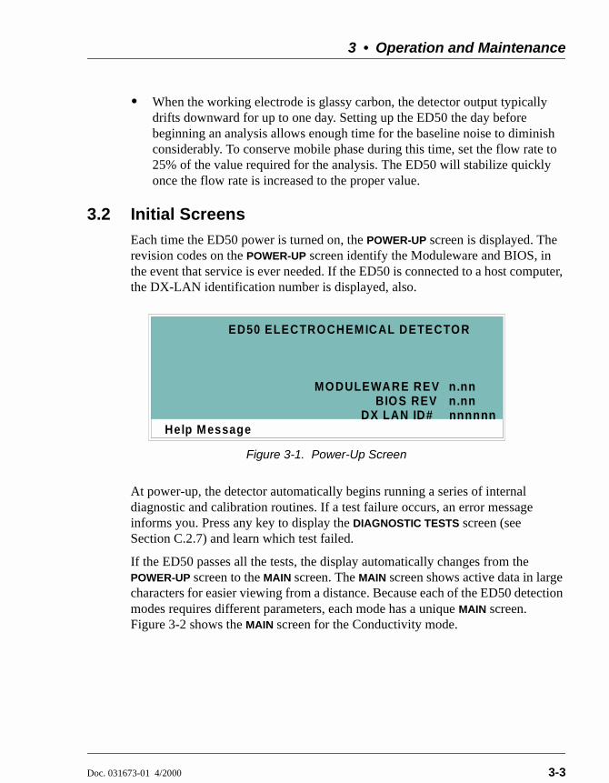
3.2 Initial ScreensEach time the ED50 power is turned on, the POWER-UP screen is displayed. The revision codes on the POWER-UP screen identify the Moduleware and BIOS, in the event that service is ever needed. If the ED50 is connected to a host computer, the DX-LAN identification number is displayed, also.
At power-up, the detector automatically begins running a series of internal diagnostic and calibration routines. If a test failure occurs, an error message informs you. Press any key to display the DIAGNOSTIC TESTS screen (see Section C.2.7) and learn which test failed.
If the ED50 passes all the tests, the display automatically changes from the POWER-UP screen to the MAIN screen. The MAIN screen shows active data in large characters for easier viewing from a distance. Because each of the ED50 detection modes requires different parameters, each mode has a unique MAIN screen. Figure 3-2 shows the MAIN screen for the Conductivity mode.
Figure 3-1. Power-Up Screen
Help Message
MODULEWARE REV
ED50 ELECTROCHEM ICAL DETECTOR
BIOS REV n.nnn.nn
nnnnnnDX LAN ID#
ED50 Electrochemical Detector
3-4 Doc. 031673-01 4/2000
Press the Menu button to go to the MENU of SCREENS. There, begin selecting parameters for the Direct control or Method control operating mode. The operating modes are described in Section 3.4 and Section 3.5.
3.3 Selecting the Control ModeTo select the control mode from the front panel:
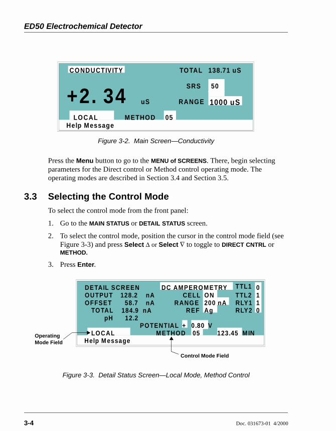
1. Go to the MAIN STATUS or DETAIL STATUS screen.
2. To select the control mode, position the cursor in the control mode field (see Figure 3-3) and press Select ∆ or Select ∇ to toggle to DIRECT CNTRL or METHOD.
3. Press Enter.
Figure 3-2. Main Screen—Conductivity
Figure 3-3. Detail Status Screen—Local Mode, Method Control
Help Message
TOTAL 138.71 uS
SRS
RANGE
50
1000 uS
LOCAL M ETHOD 05
uS+2. 34CONDUCTIVITY
Help M essage
TO TAL 184.9 nARANG E
123.45 M INLOCAL M ETHOD 05
DETAIL SCREENOUTPUTOFFSET 58.7
nAnA
TTL1TTL2RLY1RLY2
0
0
11
POTENTIAL
CELL 128.2DC AMPEROM ETRY
pH 12.2REF
ON200 nAAg
+ 0.80 VOperating Mode Field
Control Mode Field

3 • Operation and Maintenance
Doc. 031673-01 4/2000 3-5
3.4 Running Under Direct Control (Local Mode)When the Direct control operating mode is selected, real-time commands are carried out instantly and all detector settings are in effect until you change them. Changes to parameters are executed when entered. Because there are no time-based steps, the method clock is not used. The Hold/Run and Reset buttons are not operable in Direct control.
3.5 Running Under Method Control (Local Mode)In the Method control mode, a series of programmed timed events, known as a method, controls the ED50. Methods are retained in memory even when the detector power is turned off. The detection mode determines which parameters can be controlled by a method. For detailed information about method parameters, refer to the appropriate section:
Conductivity—Section C.1.4
Integrated Amperometry—Section C.1.8
DC Amperometry—Section C.1.13
3.5.1 Running a Method1. Go to the MAIN or DETAIL screen. If necessary, toggle from DIRECT
CNTRL to METHOD and from REMOTE to LOCAL.
2. In the METHOD field, enter the desired method number and press Enter. (You can also select the method number from the METHOD screen. To do so, move the cursor to the RUN field, enter a method number, and press Enter.)
3. If the method clock is already running when you enter the method number, the method starts immediately. If the clock is in Hold, press Hold/Run to start the method.
4. The elapsed time on the method clock when the method begins determines where (i.e., at what step and parameters) the method begins running:
If the method clock is at INIT or time zero, the method begins running using the INIT condition parameters, followed by the time zero step. The remaining steps will be executed according to their programmed times.

ED50 Electrochemical Detector
3-6 Doc. 031673-01 4/2000
If the method clock is greater than zero, the method begins running using the parameters specified in the step for that elapsed time. To start the method at the INIT conditions, press Reset.
3.5.2 Changing the Running MethodTo change from the method currently running and begin running a different method, enter the new method number in the RUN field on the METHOD screen and press Enter. The new method will begin running, using the parameters specified in the step for the current elapsed time. Press Reset to start the method at the INIT conditions.
3.5.3 Changing a Method-Controlled ParameterThere are three ways to change a method-controlled parameter:
Edit the currently running method, then save the changes. Changes that affect the method after the current time will be implemented, or press Reset to restart the method at the INIT conditions.
Switch to a different method.
Abort the method, go to Direct control, and enter the new parameters directly.

3 • Operation and Maintenance
Doc. 031673-01 4/2000 3-7
3.5.4 Creating a New Method1. Go to the METHOD screen for the detection mode. In the EDIT field,
enter an unused method number from 1 through 99 and press Enter or a cursor arrow button. A blank method is displayed on the screen.
The first step of every method is an initial conditions step with INIT in the TIME field. The second step is always a time step with 0.00 in the TIME field. You cannot delete these steps, although you may change their parameters.
2. Enter the parameters for the initial conditions and time 0.00 steps.
NOTE The TIME field is the only field in each method stepthat must have an entered value. Leaving any otherfield blank indicates that there is no change fromthe value selected for that parameter in thepreceding step.
3. To create a new method step, move the cursor to a blank TIME field, enter the time (in minutes) for the action to be performed, and press Enter. Enter the values for each step parameter, or leave a field blank to have the previously selected value remain in effect.
4. Repeat Step 3 to add additional steps. Up to 30 steps can be added after the time 0.00 step.
Sometimes a method contains more steps than can be displayed on the screen at one time. If there is a small v next to the time entry at the bottom of the screen, move the cursor down to view the additional
Figure 3-4. Method Screen—Conductivity
Help Message
1.6TTL RLY
01
1
M ETHOD EDIT SAVE TO RUN 253333
TIM E RANGE 2 1 20 0 0
1
OFFSET M ARKINIT0.00
v* *
2.00
TEM P COM PCOND
200 uS
SRS 100DS3 TEM P 40

ED50 Electrochemical Detector
3-8 Doc. 031673-01 4/2000
steps. If there is a caret (^) next to the top time entry, move the cursor up to view the additional steps.
5. To save the new method, move the cursor to the SAVE TO field, enter the number that appears in the EDIT field, and press Enter.
3.5.5 Editing an Existing Method
NOTE Once you save editing changes to a method, there isno way to recall the original method. To makeexperimental changes to a method while retainingthe original method in its unmodified form, save thenew method, or a copy of the original method,under a different method number.
You can modify an existing method by changing, adding, or deleting steps and/or parameters. If you edit a method while it is running, the changes are stored in memory when you SAVE TO the method number. Changes take effect as soon as they are saved.
To edit an existing method, go to the METHOD screen, enter the method number in the EDIT field, and press Enter or a cursor arrow button.
Follow the instructions in the sections below. When you finish, save the changes to the current method number or select a new number.
Changing Method Parameters
Move the cursor to the desired field and enter a new value, using the ED50 front panel buttons. Press Enter or a cursor arrow button after each editing change.

3 • Operation and Maintenance
Doc. 031673-01 4/2000 3-9
Adding a Method Step
There are two ways to add a step to an existing method:
Move the cursor on the METHOD screen to any TIME field. Enter the time and parameters for the new step, and press Enter or a cursor arrow button. If necessary, the new step is moved to the correct chronological point in the method.
Move the cursor on the METHOD screen to the line immediately preceding the intended location of the new step. Press Insert to insert a new, blank line below the cursor location. Enter the time and parameters for the new step, and then press Enter or a cursor arrow button.
Deleting a Method Step
Move the cursor on the METHOD screen to the time of the step to be deleted and press Delete twice.
Deleting an Entire Method
Move the cursor on the METHOD screen to the EDIT field and press Delete twice.
Saving a Modified Method
To replace the original method with a modified version, enter the number of the original method in the SAVE TO field and press Enter.
To retain the original method and save the modified version elsewhere in memory, enter an unused method number in the SAVE TO field and press Enter.

ED50 Electrochemical Detector
3-10 Doc. 031673-01 4/2000
3.6 Optimizing Temperature CompensationThe ED50 built-in temperature compensation stabilizes conductivity readings by correcting for changes in ambient temperature that occur during a run. For more information about temperature control and compensation, see Section 2.4.
3.6.1 With a DS3 and Conductivity Cell
When the conductivity cell is inside a DS3 Detection Stabilizer, the temperature variations of the liquid reaching the cell should be negligible. Once you set TEMP COMP on the DETAIL screen to 1.7% per ºC, it should not have to be reset.
The DS3 normally operates at a single temperature. For optimal accuracy, calibrate the conductivity cell at this temperature, using the proper temperature coefficient setting. If you select a different temperature, the temperature compensation operates on the difference and normalizes conductivity measurements to 25 °C (77 °F).
If temperature-induced baseline cycling occurs, it is probably caused by another component of the chromatography system. If the variation increases as the eluent reservoir empties, relocate the reservoir to a more temperature-stable environment and/or wrap the reservoir in insulation.
If the ambient temperature exceeds 45 °C, the DS3 may bepermanently damaged. If the DS3 is installed in an LC30Chromatography Oven, do not set the oven temperature above40 °C (104 °F).

3 • Operation and Maintenance
Doc. 031673-01 4/2000 3-11
3.6.2 With a Shielded Conductivity CellIf the conductivity cell is not inside a DS3, the baseline will drift up and down with fluctuations in laboratory temperature. This is especially noticeable when the thermostat cycles on and off in laboratories with thermostatically-controlled temperature. Selecting the proper temperature compensation factor can help to minimize the effect of temperature fluctuations.
Start by setting TEMP COMP on the DETAIL screen to 1.7%. If a sinusoidal baseline variation of the same period as the laboratory cooling or heating occurs, increase or decrease the temperature compensation setting. Continue adjusting it until you find the optimal setting; this is typically between 1.5% to 2% per ºC for most systems, suppressed or not.
If you notice a slowly increasing or decreasing temperature pattern in a laboratory without a temperature control system, look for a corresponding baseline drift. If this drift occurs, adjust the temperature compensation setting until you find the optimal setting.

ED50 Electrochemical Detector
3-12 Doc. 031673-01 4/2000
3.7 WaveformsA waveform is a series of steps, defined as points on a plot of potential vs. time. Waveforms must be defined for the Integrated Amperometry and Voltammetry modes. Entering a waveform is similar to entering a method.
Figure 3-5 shows an example waveform and the waveform program that created it. In this program, the potential does not need to be entered in Step 1 because it remains the same as in Step 0. After Step 6, the waveform automatically reverts to the Step 0 potential.
Figure 3-5. Sample Waveform
Integration
Tim e (sec)
Potential(Volts)
0.1 V
0.7 V
-0.1 V
0.2 0.4 0.6 0.8 1.0
Step 1 Step 2
Step 3 Step 4
Step 5 Step 6
Step 0
Step
0123456
Tim e
0.000.200.400.410.600.611.00
Potential
0.10
0.10 0.70 0.70-0.10-0.10
Integrate
BeginEnd
0.0
3 • Operation and Maintenance
Doc. 031673-01 4/2000 3-13
3.8 VoltammetryThe Voltammetry mode is used to develop waveforms for Integrated Amperometry and to determine appropriate potentials for DC Amperometry. It is similar to Integrated Amperometry in that a repeating potential vs. time waveform is applied to the cell. It differs in that the ED50 output is the cell current, which is continuously monitored and reported as in DC Amperometry. The information gained by studying instantaneous cell current can be useful for developing waveforms for Integrated Amperometry.
With the pump on, and mobile phase and analyte flowing through the amperometry cell, results are similar to those obtained by rotated disk voltammetry in a standard beaker cell. With the flow off, rapid depletion of analyte next to the working electrode is typical of thin-layer voltammetry.
To perform cyclic voltammetry with the ED50, program a triangle wave as the waveform (see Section 3.8.3).
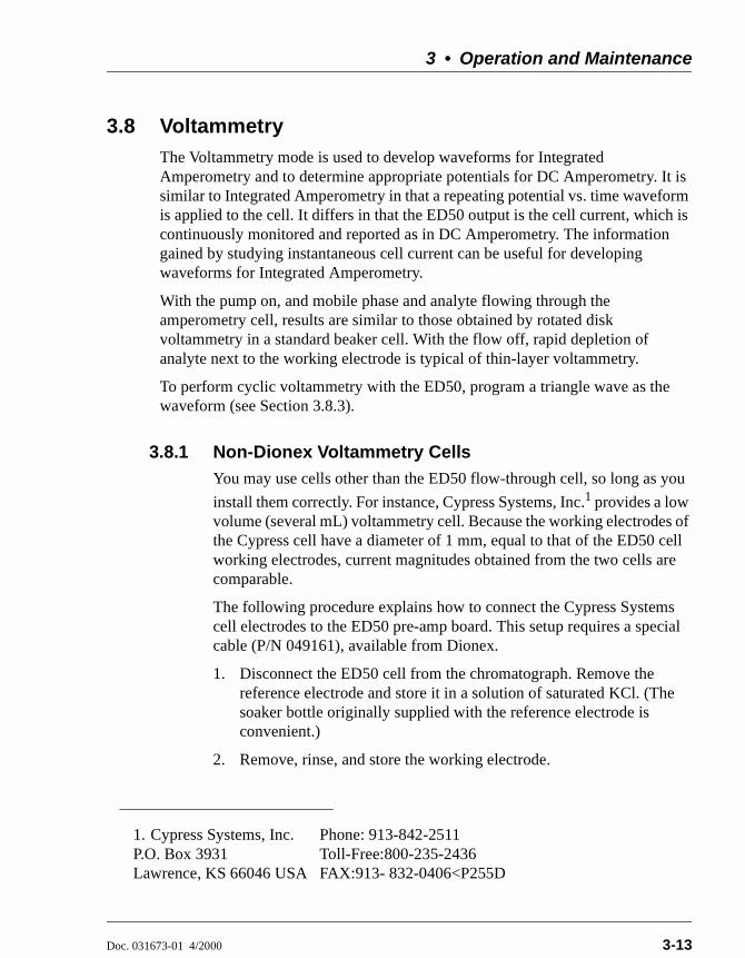
3.8.1 Non-Dionex Voltammetry CellsYou may use cells other than the ED50 flow-through cell, so long as you
install them correctly. For instance, Cypress Systems, Inc.1 provides a low volume (several mL) voltammetry cell. Because the working electrodes of the Cypress cell have a diameter of 1 mm, equal to that of the ED50 cell working electrodes, current magnitudes obtained from the two cells are comparable.
The following procedure explains how to connect the Cypress Systems cell electrodes to the ED50 pre-amp board. This setup requires a special cable (P/N 049161), available from Dionex.
1. Disconnect the ED50 cell from the chromatograph. Remove the reference electrode and store it in a solution of saturated KCl. (The soaker bottle originally supplied with the reference electrode is convenient.)
2. Remove, rinse, and store the working electrode.
1. Cypress Systems, Inc. Phone: 913-842-2511P.O. Box 3931 Toll-Free:800-235-2436Lawrence, KS 66046 USA FAX:913- 832-0406<P255D
ED50 Electrochemical Detector
3-14 Doc. 031673-01 4/2000
3. Rinse the cell flow path to prevent mobile phase from precipitating in the cell. Dry the cell.
4. Attach the special cell cable (P/N 049161) to the pre-amp board as follows:
a. Plug the two-pin socket of the cable into the working electrode connector (J1) on the board. The connector can be attached in either direction.
b. Plug the three-pin socket of the cable into the reference electrode connector (J2). The actual connection is to the center pin, so the connector can be attached in either direction. Because there is no connection to the pH input, disregard the pH readings reported by the detector.
c. Attach the spade lug (counterelectrode) to the cell body, using the cell cover thumbscrew.
5. Attach the three pins on the other end of the special cell cable to the cell electrodes, as follows:
Black: Working ElectrodeWhite: Reference ElectrodeRed: Counterelectrode

3 • Operation and Maintenance
Doc. 031673-01 4/2000 3-15
3.8.2 Recorder ConnectionsCell current is monitored in the Voltammetry mode by connecting the ED50 analog output to a recording device. Use the recorder negative and positive connections on the SCR (Supply Control/Relay) card (pins 1 and 2). See Section F.1 of Appendix F for the Recorder/Diagnostic Signal pinouts.
Data output from cyclic voltammetry is traditionally plotted as current vs. potential, rather than time. This is accomplished by connecting the Amperometry Cell Drive output on the SCR card (pin 7) to the X axis of an X-Y recorder, oscilloscope, or a computer equipped with A/D conversion and X-Y plotting software. Note that PeakNet Software does not currently support the Voltammetry mode.
NOTE The cell drive output polarity is reversed. Connectthe negative input from the recording device to pin7, and the positive input to pin 10.
To place zero current in the middle of the Y axis, set the ZERO POSITION on the ANALOG OUT SETUP screen to 50%. Select the most sensitive setting for the range that keeps the current on scale; a less sensitive analog output range may produce an output with excessive digital steps.
ED50 Electrochemical Detector
3-16 Doc. 031673-01 4/2000
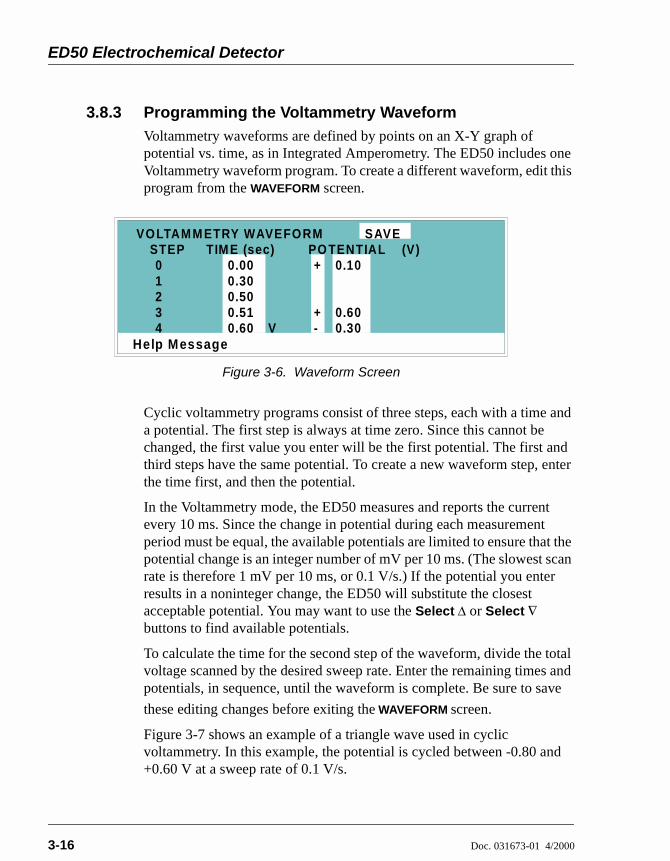
3.8.3 Programming the Voltammetry WaveformVoltammetry waveforms are defined by points on an X-Y graph of potential vs. time, as in Integrated Amperometry. The ED50 includes one Voltammetry waveform program. To create a different waveform, edit this program from the WAVEFORM screen.
Cyclic voltammetry programs consist of three steps, each with a time and a potential. The first step is always at time zero. Since this cannot be changed, the first value you enter will be the first potential. The first and third steps have the same potential. To create a new waveform step, enter the time first, and then the potential.
In the Voltammetry mode, the ED50 measures and reports the current every 10 ms. Since the change in potential during each measurement period must be equal, the available potentials are limited to ensure that the potential change is an integer number of mV per 10 ms. (The slowest scan rate is therefore 1 mV per 10 ms, or 0.1 V/s.) If the potential you enter results in a noninteger change, the ED50 will substitute the closest acceptable potential. You may want to use the Select ∆ or Select ∇ buttons to find available potentials.
To calculate the time for the second step of the waveform, divide the total voltage scanned by the desired sweep rate. Enter the remaining times and potentials, in sequence, until the waveform is complete. Be sure to save
these editing changes before exiting the WAVEFORM screen.
Figure 3-7 shows an example of a triangle wave used in cyclic voltammetry. In this example, the potential is cycled between -0.80 and +0.60 V at a sweep rate of 0.1 V/s.
Figure 3-6. Waveform Screen
Help Message
STEP TIM E (sec)01234
0.000.300.500.510.60
+
+-V
0.10
0.600.30
VOLTAM M ETRY WAVEFORM SAVEPO TENTIAL (V)

3 • Operation and Maintenance
Doc. 031673-01 4/2000 3-17
The first waveform step at 0.00s is the initial potential of -0.80 V. To calculate the time for the second step, divide the total voltage scanned by the desired sweep rate:
The time for the second step is 14 s. The third step is an equal interval later, or 28 s.
3.8.4 Running the WaveformWhen the cell is turned on, the ED50 applies the initial potential programmed at time zero. At that point, you may do any of the following:
To begin the waveform, press Run.
To freeze the scan at the current potential, press Hold. Press Run to continue from that point.
To return to the initial potential without stopping the scan, press Reset.
To return to the initial potential and hold at that potential, press Hold and Reset, in that order.
Figure 3-7. Cyclic Voltammetry Example
TotalVoltageScannedSweepRate
---------------------------------------------------------- 1.4V0.1V s⁄-----------------= 14s=

ED50 Electrochemical Detector
3-18 Doc. 031673-01 4/2000
3.9 Routine MaintenanceThis section describes routine maintenance procedures that can be performed by the user. Any other maintenance procedures must be performed by qualified Dionex personnel.
NOTE The ED50 electronic components are not customer-serviceable. Repair of electronic components must beperformed by Dionex.
Periodically check liquid line connections to the cells (inside the chromatography module) for leaks and clean up any spills.
The ED50 amperometry cells are designed to require minimal maintenance. If you observe the following precautions, the working electrode should rarely require polishing.
To prevent electrode contamination:
a. Run only clean, filtered samples.
b. Prepare all eluents with high purity deionized water.
c. Avoid contamination of the cell with incompatible eluents.
Never apply potential to the electrode unless a stream of eluent or water is flowing through the cell.
Be careful to keep the polished surface of the amperometry cell body clean and dry. The gold, spring-loaded working electrode contact must also remain clean and dry. If a salt bridge forms, it can cause an electrical short between the working electrode contact and the cell body.
Over the lifetime of the working electrode, it is normal for the surface to gradually become pitted. However, if the electrode becomes discolored or if you notice a degradation in performance (baseline noise, tailing peaks, etc.), polish the electrode as instructed in Section 5.5.

3 • Operation and Maintenance
Doc. 031673-01 4/2000 3-19
3.10 Shutdown Whenever the amperometry cell is not being used, remove the pH reference
electrode and store it in a solution of saturated KCl, as instructed in the procedure below. If the reference electrode is left in the cell and mobile phase is not being pumped through the cell, the reference electrode frit may partially dry out. If this occurs, regenerate the electrode by soaking it in a solution of 1 M KCl plus 1 M HCl.
Storing the amperometry cell:
1. Prepare a saturated solution of KCl in deionized water.
2. Remove the cap of the soaker bottle in which the electrode was shipped.
3. Fill the soaker bottle at least three-fourths full with the prepared KCl solution.
4. Remove the pH reference electrode from the cell.
5. Slip the electrode through the hole in the soaker bottle lid until the electrode cap bottoms out on the top of the lid.
6. Screw the soaker bottle lid, with the electrode attached, onto the soaker bottle.
7. Store the assembly in the original shipping box.
ED50 Electrochemical Detector
3-20 Doc. 031673-01 4/2000

Doc. 031673-01 4/2000 4-1
4 • Troubleshooting
This chapter is a guide to troubleshooting problems that may occur while operating the ED50 Electrochemical Detector. Turn to the section that best describes the operating problem. There, the possible causes of the problem are listed in order of probability, along with the recommended courses of action. For additional help, refer to Appendix C for instructions on running the ED50 diagnostics program.
If you are unable to eliminate a problem, contact Dionex. In the U.S., call 1-800-346-6390 and select the Technical Support option. Outside the U.S., call the nearest Dionex office.
4.1 No Detector Response Cell is off
Turn on the cell (from the MAIN or DETAIL screen).
Analog output range set too high; although the display indicates a response, no recorder response observed
Select a more sensitive analog output range.
Wrong full-scale output (or no full-scale output) selected
Select 0.01, 0.10, or 1 volt full-scale.
No flow from pump
Check the pressure reading on the pump to verify that the pump is on.
Detector offset out of range
Press Offset on the ED50 front panel.

ED50 Electrochemical Detector
4-2 Doc. 031673-01 4/2000
4.2 Low Detector Output Analog output range set too high; although the display indicates a
response, no recorder response observed
Select a more sensitive analog output range.
Insufficient sample injected
Increase the injection size or concentration.
(Conductivity mode)—Cell out of calibration
Recalibrate the conductivity cell (see Section 5.4).
(DC Amperometry and Integrated Amperometry modes)— Working electrode fouled
Polish the working electrode (see Section 5.5).
4.3 High Detector Output Auto offset not activated recently
Press Offset on the ED50 front panel before making an injection.
(Conductivity mode)—Regenerant fails to suppress background
Use a higher regenerant flow rate.
(Integrated Amperometry mode)—Excessive number of integration periods
Integration periods were not properly deleted during editing; delete any unnecessary integration periods now.
(DC Amperometry and Integrated Amperometry modes)— Amperometry cell working electrode shorted to counterelectrode
Polish the working electrode (see Section 5.5). Remove any precipitate on the counterelectrode by cleaning the spot directly opposite the working electrode with a wet paper towel and coarse polishing compound (P/N 036319).

4 • Troubleshooting
Doc. 031673-01 4/2000 4-3
4.4 Noisy or Drifting Baseline Flow system leak ahead of cell; erratic baseline
Check all fittings and liquid lines for leaks. Tighten or, if necessary, replace all liquid line connections. If the connections are made with ferrule fittings, first refer to Installation of Dionex Ferrule Fittings for tightening requirements.
Pump not properly primed
Prime the pump as instructed in the pump manual.
Rapid changes in ambient temperature
Direct heating and air conditioning vents away from the cell.
Install the cell in an LC30 Chromatography Oven.
Insufficient system equilibration following any changes to operating parameters; especially apparent when operating at high sensitivities
Allow longer system equilibration before beginning operation.
(Conductivity mode)—Air trapped in cell; excessive regular pulses in baseline
Remove the trapped air (see Section 5.2). To prevent air from becoming trapped in the cell in the future, increase backpressure on the cell by lengthening the waste line.
(Conductivity mode)—Inappropriate suppressor operating conditions
Refer to the suppressor manual for the correct operating conditions.
(Conductivity mode)—Temperature compensation setting not optimized
Optimize the selected setting (see Section 3.6).
Purchase a cell with a DS3 Detection Stabilizer (P/N 044130).
(DC Amperometry and Integrated Amperometry modes)—Frequent, random spikes in the baseline
The reference electrode is plugged. First, try regenerating the reference electrode frit by soaking the electrode in a solution of 1 M KCl plus 1 M HCl. If this does not eliminate the spiking, replace the electrode (P/N 046333).
ED50 Electrochemical Detector
4-4 Doc. 031673-01 4/2000
(DC Amperometry and Integrated Amperometry modes)—Regular baseline oscillation on high-sensitivity ranges
Reconnect the short length of titanium tubing to the cell inlet.
(DC Amperometry and Integrated Amperometry modes)—Dirty or pitted working electrode
Polish the working electrode (see Section 5.5).
(Integrated Amperometry mode)—Regular baseline oscillations
The water used to prepare the eluent contains trace sugar contaminants. Remake the eluent, using high purity DI water containing no contaminants.
4.5 Tailing Peaks (DC Amperometry and Integrated Amperometry modes)—Dirty or
pitted working electrode
Polish the working electrode (see Section 5.5).
4.6 Amperometry Cell pH Readout Always 7.0 Short circuit in pH reference electrode
Check connections to the cell pre-amp board.
Look for salt on the cell pre-amp board.
Replace the pH reference electrode (P/N 046333).
4.7 Cannot Set Amperometry Cell pH Readout to 7.0 Inaccurate calibration buffer
Use a pH meter to check the pH of the buffer.
Contaminated pH reference electrode
Soak the reference electrode in a solution containing 1 M KCl and 1 M HCl.
Replace the electrode (P/N 046333).
4 • Troubleshooting
Doc. 031673-01 4/2000 4-5
4.8 No Amperometry Cell pH Readout Disconnected or broken pH electrode wire(s)
Fix the connections or replace the electrode (P/N 046333).
Uncalibrated pH electrode
Calibrate the pH reference electrode from the pH CALIBRATION screen.
4.9 Discolored pH Reference ElectrodeThis is not a problem; although the electrode normally becomes discolored from prolonged use at high pH, the change in color does not impair its correct functioning. The reference electrode is a consumable item which typically lasts 6 months in normal use (see Section 4.11).
4.10 Leaking pH Reference Electrode Defective pH reference electrode
Replace the pH reference electrode O-ring (see Section 5.6).

ED50 Electrochemical Detector
4-6 Doc. 031673-01 4/2000
4.11 Shift in Ag/AgCl Reference Potential Faulty reference electrode
A shift in reference potential causes a shift in the effective potential applied to the working electrode. For example, an applied potential of 0.1V, using an electrode with a shift of 50 mV, is equivalent to an applied potential of 0.15V for a new reference electrode with no shift.
Following the steps below, measure the Ag/AgCl reference electrode potential shift by comparing it to the potential shift of a new electrode. It is convenient to keep a spare reference electrode (P/N 046333) on hand for this purpose.
1. Turn off the cell.
2. Remove the reference electrode from the cell body, unplug the electrode, and rinse it in deionized water.
3. Locate the reference electrode connector (J2) on the cell pre-amp board. Short the two pins of the connector together, using a short piece of wire or a metal clip. Do not allow the wire or metal clip to contact the cell body or any other conductor.
4. Select CAL on the pH CALIBRATION screen and press Enter. When the “pH 7 Calibration Complete” message appears, remove the wire or clip from J2.
5. Connect the reference electrode being tested to J2 by turning the electrode at right angles and plugging the center connector of the three-connector socket into the pin labeled “pH.”
6. Connect the new reference electrode to J2 by turning the electrode at right angles and plugging the center connector of the three-connector socket into the pin labeled “Ag.”
7. Immerse both reference electrodes in a saturated solution of KCl.
8. When the pH reading has stabilized, calculate the difference in potential between the two reference electrodes, using the following equation:
For most applications, a difference of less than 50 mV is insignificant. Therefore, the electrode can still be considered good if the voltage difference is less than 50 mV.
Difference Volts( ) 7 pHreading–( ) 0.06×=

4 • Troubleshooting
Doc. 031673-01 4/2000 4-7
If the difference is greater than 50 mV, try regenerating the electrode by soaking it in a solution of 1M KCl plus 1M HCl. If this does not reduce the potential shift, replace the electrode.
4.12 Liquid Leaks from the DS3When a leak is detected, the DS3 leak sensor signals the CPU. If more than 5 mL of liquid accumulates in the DS3, the excess will be drained via the spill overflow line (see Figure 2-6).
Loose or defective fittings, or overpressurization caused by a restriction
Check the waste line for blockage; a trapped particle can plug the line, causing a restriction and/or leak. If necessary, clear the waste line by reversing the direction of flow.
Make sure the plumbing downstream from the DS3 is clear; a blockage in the plumbing may overpressurize the DS3, causing it to leak.
Make sure the downstream backpressure coils are appropriate for the operating flow rate (see Section B.2.4).
Follow the steps below to disassemble the DS3 and inspect it for the source of the leak. Test and dry the DS3 before reassembly.
1. Turn off the ED50 power.
2. Disconnect the DS3 cables.
3. Disconnect the DS3 inlet and outlet lines. Do not misplace the ferrule fittings at the end of the tubing (see Figure 4-1).
4. Remove the DS3 by lifting it upward and then pulling it away from its mounting location. Place the DS3 on the workbench.
5. Open both latches on the DS3 and carefully lift off the top half of the cover, along with its insulating foam insert, exposing an aluminum box (see Figure 4-1).
6. Remove the box from the bottom half of the cover.
7. Remove the four Phillips screws securing the top of the box to its bottom plate. Carefully separate the two parts, exposing the cell (see Figure 4-2)7. Lay the top aside, being careful not to pull or stress the group of wires that connect the two parts.

ED50 Electrochemical Detector
4-8 Doc. 031673-01 4/2000
8. Check the inlet and outlet cell fittings for leaks. Tighten or replace if necessary.
9. Dry the DS3, test for leaks, and reassemble. Make sure the foam insert is adjusted evenly around the various DS3 components, with no pinching or folding. Check that the top and bottom inserts meet on all sides before latching the cover.
Figure 4-1. DS3 Exploded View
InsulatingFoamInsertBottom
Cover
Cables
Alum inumBox
Spill OverflowLine
PhillipsScrews (4)
TopCover
Inlet Outlet

4 • Troubleshooting
Doc. 031673-01 4/2000 4-9
Liquid seeping from around cell cables
The cell is inoperable and should be returned to Dionex for repair or exchange. Contact Dionex for assistance.
Figure 4-2. DS3 Interior Components
InletOutlet
Grounding Strap
Cell
InletFitting
PhillipsScrews
OutletFitting
ED50 Electrochemical Detector
4-10 Doc. 031673-01 4/2000
4.13 DS3 Temperature Inaccurate “DS3 SET POINT XX C READY” message displays continuously
The control sensor may be faulty. Remove the cover of the DS3 and measure the temperature of the aluminum housing, using any surface thermometer. The cell sensor can be read on the detector and should be within 1 or 2 degrees of the DS3 set point temperature.
“DS3 SET POINT XX C UNDER TMP” or “DS3 SET POINT XX C OVER TMP” message displays continuously
Verify that the set temperature is at least 5 °C above or below the external DS3 temperature. Allow 30 to 60 minutes for the DS3 to heat or cool.
At high flow rates and temperature settings much over ambient, the DS3 requires more time to heat. In extreme cases, such as a cold room and a high DS3 set point, the DS3 may not be able to reach the set point temperature.
DS3 does not heat
Remove the cover and inspect the DS3 for broken or shorted wires or moisture bridging the control thermistor. If a wire is broken or shorted, replace the wire or contact Dionex for assistance. If a leak has caused a short, fix the leak and dry the control sensor.
“DS3 SET POINT XX C READY” message displays intermittently
Check that the heater transistors are snug and the control sensor has not been pulled out of the heat exchanger plate.

4 • Troubleshooting
Doc. 031673-01 4/2000 4-11
4.14 Conductivity Inaccurate Cell constant reported on CONDUCTIVITY CALIBRATION screen after cell
calibration is not 130 to 190 µS
The DS3 has not reached its set point temperature. Set the intended operating temperature and wait until 5 minutes after the “NOT READY” message is displayed, or until the reading is stable.
Make sure the selected temperature compensation setting is 1.6%/°C. Except at 25 °C, an incorrect temperature compensation setting can cause an incorrect reading.
The 1 mM KCl calibration solution is spoiled, or there was a mixing error. Make fresh solution.
The electrodes are fouled by grease, precipitate, etc. Flush with a suitable solvent, such as acid, and then flush with 1 mM KCl until the reading is stable.
There are internal leaks, broken or shorted cell or sensor wires. Check the sensor by comparing the cell temperature readout with the actual DS3 temperature. If necessary, return the cell to Dionex for repair. Do not remove the cover plate; this will break the hermetic seal and void your warranty.
Cell temperature readout deviates by more than 2°C from DS3 set temperature
This indicates a serious cell or DS3 sensor problem. Contact Dionex for assistance.

ED50 Electrochemical Detector
4-12 Doc. 031673-01 4/2000
4.15 Faulty DX-LAN Communication DX-LAN interface incorrectly installed
See Section B.2.2 for 10BASE-T connection instructions or Section B.2.3 for BNC connection instructions.
4.16 Diagnostics
NOTE Before running the ED50 diagnostics, use thetroubleshooting information in this chapter to isolatenon-electronic problems.
The ED50 Moduleware includes several diagnostic tests of the electronics. To access these, select the DIAGNOSTIC MENU from the MENU of SCREENS. All of the diagnostic screens are described in Appendix C.
Figure 4-3. Diagnostic Menu Screen
Help M essage
POW ER-UP SCREENELAPSED TIM EANALO G STATUS DX- LAN STATUS
DIAGNOSTIC TESTSLEAK CAL & STATUSSIGNAL STATISTICSCALIBRATE CD CELL
12345
678
DIAGNOSTIC MENU
KEYBOARD TEST9
10 pH CALIBRATION

Doc. 031673-01 4/2000 5-1
5 • Service
This chapter describes routine service procedures that the user can perform. All other procedures must be performed by Dionex personnel.
NOTE The ED50 electronics components are not customer-serviceable. Repair of electronics components must beperformed by Dionex.
The CPU card contains a lithium battery. If the CPU card is replaced, dispose of the used battery according to the manufacturer's instructions.
Before replacing any parts, refer to the troubleshooting information in Chapter 4 to isolate the cause of the problem. To contact Dionex in the U.S., call 1-800-346-6390 and select the Technical Support option. Outside the U.S., call the nearest Dionex office.
Substituting non-Dionex parts may impair ED50 performance, thereby voiding the product warranty. Refer to the warranty statement in the Dionex Terms and Conditions for more information.

ED50 Electrochemical Detector
5-2 Doc. 031673-01 4/2000
5.1 Eliminating Liquid LeaksThe PEEK version of the ED50 is plumbed with 1.60-mm (1/16-in) PEEK tubing, Dionex ferrule fittings (P/N 043276), and 10-32 fitting bolts (P/N 043275). For tightening requirements, see Installation of Dionex Ferrule Fittings.
5.2 Removing Trapped Air from the CellAir bubbles in the cell can cause regular pulsations of the baseline, random noise, and low readings. Air may have been introduced in the columns during installation, or may result from outgassing of the mobile phase. Connecting a backpressure line to the cell applies enough backpressure to shrink bubbles, thereby allowing them to pass more easily through the cell.
1. Connect a piece of 0.25-mm (0.010-in) ID tubing (P/N 042690), with fittings on both ends, to the cell outlet. Make the line 1 m long for a flow rate of 1.0 mL/min, 2 m for 0.5 mL/min, etc.
2. Use tubing with an inner diameter of at least 1mm (0.04 in) the rest of the way to the waste container. Use a union (P/N 042627) to connect the backpressure line to the waste line.
5.3 Replacing the DS3 CellFollow the steps below to disassemble the DS3 and replace the cell. After replacing the cell you must recalibrate it (see Section 5.4).
1. Turn off the ED50 power.
2. Disconnect the DS3 cables.
3. Disconnect the DS3 inlet and outlet lines. Do not misplace the ferrule fittings at the end of the tubing (see Figure 5-1).
4. Remove the DS3 by lifting it upward and then pulling it away from its mounting location. Place the DS3 on the workbench.
5. Open both latches on the DS3 and carefully lift off the top half of the cover, along with its insulating foam insert, exposing an aluminum box (see Figure 4-1).
Make sure the added backpressure does not exceed 0.20 MPa(30 psi). Avoid large increases in flow rate that would result inmore than 1.4 MPa (200 psi) being applied to the cell.

5 • Service
Doc. 031673-01 4/2000 5-3
6. Remove the box from the bottom half of the cover.
7. Remove the four Phillips screws securing the top of the box to its bottom plate. Carefully separate the two parts, exposing the cell (see Figure 5-1). Lay the top aside, being careful not to pull or stress the group of wires that connect the two parts.
8. Disconnect the grounding strap. Remove the two cell mounting screws.
9. Rotate the cell inlet tube fitting counterclockwise. Let the cell body back away from the fitting until the fitting threads are fully disengaged. Do not lose the ferrule.
10. Check that the end of the inner Tefzel tubing is flush with the end of the plastic sleeve. If necessary, trim the sleeve slightly to prevent dispersion. Push the tubing into the new cell until it bottoms out in the hole; then, hold the tubing in place while tightening the nut.
11. After testing for liquid leaks, dry the DS3 and reassemble. Make sure the foam insert is adjusted evenly around the various components, with no pinching or folding. Before latching the cover, make sure the top and bottom inserts meet on all sides.
12. Reconnect the DS3 cables and turn on the ED50 power. Calibrate the cell constant (see Section 5.4).
Figure 5-1. DS3 Interior Components
InletOutlet
Grounding Strap
Cell
InletFitting
PhillipsScrews
OutletFitting

ED50 Electrochemical Detector
5-4 Doc. 031673-01 4/2000
5.4 Calibrating the CellEvery conductivity cell is calibrated before it is shipped from the factory. The cell calibration constant is recorded on a tag attached to the cell cable, and is also stored in permanent detector memory for use when calculating the measured conductivity.
The calibration constant normally should be recalibrated every six months. To check the value entered in memory, select CALIBRATE CD CELL from the DIAGNOSTIC MENU to display the CALIBRATE CONDUCTIVITY CELL screen. If the cell calibration constant shown on the screen does not match the value recorded on the tag, do one of the following:
If this is a replacement cell, enter the calibration constant value from the tag into the screen field.
If the cell has been in use for some time, calibrate the cell at 147.00 µS/cm. This automatically enters a new value for the cell calibration constant into ED50 memory.
To calibrate the cell at 147.00 µS/cm, follow the steps below.
1. Disconnect the pump output line from the LC10 Chromatography Organizer, LC20 Chromatography Enclosure, or LC30 Chromatography Oven.
2. Connect the pump output directly to the inlet of the DS3 or the shielded cell.
3. Pump 0.001 M KCl calibration solution through the cell. Conductivity is slightly flow-rate sensitive, so select the flow rate used in the majority of your applications.
4. Set TEMP COMP on the DETAIL screen to 1.7%.
5. If using a DS3, set DS3 SETPOINT on the DETAIL screen to the intended operating point. Wait until the “DS3 READY” message appears.
6. Wait until the conductivity reading stabilizes (within 0.1 µS), and then, on the CALIBRATE CONDUCTIVITY CELL screen, select CAL and press Enter to calibrate the cell.
7. After calibration, the conductivity reading should be exactly 147.00 µS/cm. A new value for the cell constant is shown on the CALIBRATE CONDUCTIVITY CELL screen; this value is also entered in memory.

5 • Service
Doc. 031673-01 4/2000 5-5
8. Flush the KCl solution from the system by pumping deionized water through the DS3 or cell lines. When the conductivity reading drops to near zero, stop the pump.
9. Disconnect the pump from the DS3 or shielded cell.
10. Reconnect the pump to the chromatography module.
11. Reconnect the liquid line from the suppressor outlet to the cell inlet.
12. Reset TEMP COMP to the optimal value for the eluent.
13. Set the pump to a flow rate that is appropriate for the system in use.
5.5 Polishing the Working ElectrodesPolish all working electrodes with fine polishing compound before initial installation in the amperometry cell. Later, if you observe high background current, a decrease in sensitivity, or other degradation in detector output, polish the working electrode to clean it and restore performance.
Section 5.5.1 describes a mild cleaning procedure for gold working electrodes only. If this procedure is not effective, go on to Section 5.5.2.
Section 5.5.2 describes a more aggressive cleaning procedure, in which the electrode is cleaned with fine and coarse polishing compounds. Since the cell may need at least 12 hours to re-equilibrate after polishing, perform this procedure only when essential. This procedure applies to all ED50 working electrodes.
To polish electrodes with fine polishing compound before initial installation in the amperometry cell, follow the instructions in Section 5.5.2.
5.5.1 Polishing with a Pencil Eraser (Gold Electrodes Only)1. Unscrew the wing nuts holding the working electrode to the cell body,
and carefully separate the parts. Handle the cell gasket and the inside surfaces of the cell carefully, to prevent scratches which may subsequently cause leaks.
2. Rub the electrode surface with the pink eraser (P/N 049721) provided in the polishing kit (P/N 036313) until all traces of discoloration have been removed from the electrode.

ED50 Electrochemical Detector
5-6 Doc. 031673-01 4/2000
3. Rinse the electrode thoroughly with water. Wipe the surface with tissue to remove any remaining traces of eraser.
4. Reassemble the cell. Reapply the potential to the electrode and equilibrate for 1 to 2 hours while eluent flows slowly through the cell.
5. If detector performance does not improve, clean the electrode with fine polishing compound (P/N 036318). If you notice a noisy baseline or tailing peaks, first polish the electrode with coarse polishing compound (P/N 036319), followed with fine polishing compound. See Section 5.5.2 for instructions.
6. After carefully removing all traces of polishing compound, reassemble the cell. Resume eluent flow for re-equilibration and apply the electrode potential. You can expect the baseline to drift for about 1 hour as the cell re-equilibrates. Peak area values may require up to 12 hours to stabilize.
5.5.2 Polishing with Polishing Compounds1. Unscrew the wing nuts holding the working electrode to the cell body,
and carefully separate the parts. Handle the cell gasket and the inside surfaces of the cell carefully, to prevent scratches which may subsequently cause leaks.
2. Locate the polishing kit (P/N 036313) shipped with the amperometry cell. The kit contains two polishing pads (P/N 036321), a bottle of fine polishing compound (P/N 036318), and a bottle of coarse polishing compound (P/N 036319).
3. Using indelible ink, mark the plastic side of each pad to designate whether it is for use with the coarse or fine polishing compound. Also mark the fine pad to designate for which working electrode type it is to be used.
NOTE Do not use the same fine polishing pad to polishmore than one type of working electrode; this cancontaminate the electrode surface withmicroparticles from the other working electrodes. Aseparate polishing pad is shipped with each type ofworking electrode. Using indelible ink, mark eachpad to indicate the working electrode with which itis used.
5 • Service
Doc. 031673-01 4/2000 5-7
4. Moisten the plastic side of the fine polishing pad slightly with water and place it on a smooth, flat surface.
5. Sprinkle about one-half gram of polishing compound in the center of the suede side of the polishing pad. Add enough deionized water to make a thick paste.
If you are polishing the electrode because of degradation of performance, such as a noisy baseline or tailing peaks, first use the coarse polishing compound.
If you are polishing the electrode before initial installation, use the fine polishing compound.
6. Using the working electrode block, spread the paste evenly over the pad. Then, applying firm pressure in a figure eight motion, polish the surface of the electrode block for about one minute. If the pad dries out while polishing, add water sparingly.
7. Use deionized water to rinse off all traces of polishing compound from the electrode block. An ultrasonic cleaner is effective for thoroughly cleaning the electrode block. Carefully wipe the surface of the block with a soft damp cloth or damp paper towel.
8. If you used the coarse polishing compound in Step 5, repeat Steps 5 through 7 with the fine compound.
9. Inspect the surface of the working electrode to make sure that it is clean.
NOTE Do not rinse the polishing compound from the padsafter polishing is complete. The polishing pads arereusable. After the initial use, add only enoughpolishing compound to maintain the coating on thepad.
10. Reassemble the cell. Reapply the electrode potential and resume eluent flow. The baseline will drift for more than 1 hour as the cell re-equilibrates. Peak area values may require up to 12 hours to stabilize.

ED50 Electrochemical Detector
5-8 Doc. 031673-01 4/2000
5.6 Replacing the pH Reference Electrode O-RingA defective pH reference electrode O-ring can cause liquid leaks from the pH reference electrode or compression nut area when the cell operating pressure is below 700 kPa (100 psi).
1. Remove the pH reference electrode from the reference electrode cavity.
2. With a sharp instrument (such as a pin), stick the old reference electrode O-ring and pull it out of the reference electrode cavity. Be careful not to scratch the cell body. Do not lose the stop ring (P/N 045967) located below the O-ring. The stop ring prevents the pH reference electrode from bottoming out and thereby damaging the electrode.
3. Verify that the stop ring is in place at the bottom of the cavity. Using a blunt instrument, push the new O-ring (P/N 048410) into the groove within the cavity. Verify that the new O-ring is seated properly.
NOTE As removing the O-ring destroys it, always replacethe old O-ring with a new one.
4. Reinstall the pH reference electrode in the reference electrode cavity.

5 • Service
Doc. 031673-01 4/2000 5-9
5.7 Replacing the Main Power FusesThe fuse holder is in the main power receptacle on the ED50 rear panel.
1. Turn off the main power.
2. A recessed lock is located on each side of the fuse holder (see Figure 5-2). Using a small screwdriver, push each lock toward the center to release it. The fuse holder pops out slightly when the locks release. When both locks are released, pull the fuse holder straight out of its compartment.
3. The holder contains two fuses. Replace both with new 3.15 amp fast-blow IEC127 fuses (P/N 954745). Dionex recommends replacing both fuses even though only one has failed.
4. Reinsert the fuse holder into its compartment. The fuse holder is keyed to fit only in its proper orientation. Apply sufficient pressure evenly against the holder to engage the two locks. The holder is flush against the panel when both locks are engaged.
5. Reconnect the main power cord and turn on the power.
HIGH VOLTAGE—Disconnect the main power cord from itssource and also from the rear panel of the ED50.
Figure 5-2. Main Power Fuse Holder
Fuse HolderLocking Spring
Insert screwdriverand tw ist to release
(each side)
Fuses (2)
Key
M ain PowerReceptacle
Fuse Holder(side view)

ED50 Electrochemical Detector
5-10 Doc. 031673-01 4/2000
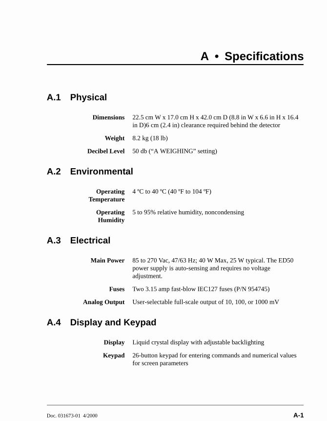
Doc. 031673-01 4/2000 A-1
A • Specifications
A.1 Physical
A.2 Environmental
A.3 Electrical
A.4 Display and Keypad
Dimensions 22.5 cm W x 17.0 cm H x 42.0 cm D (8.8 in W x 6.6 in H x 16.4 in D)6 cm (2.4 in) clearance required behind the detector
Weight 8.2 kg (18 lb)
Decibel Level 50 db (“A WEIGHING” setting)
OperatingTemperature
4 ºC to 40 ºC (40 ºF to 104 ºF)
OperatingHumidity
5 to 95% relative humidity, noncondensing
Main Power 85 to 270 Vac, 47/63 Hz; 40 W Max, 25 W typical. The ED50 power supply is auto-sensing and requires no voltage adjustment.
Fuses Two 3.15 amp fast-blow IEC127 fuses (P/N 954745)
Analog Output User-selectable full-scale output of 10, 100, or 1000 mV
Display Liquid crystal display with adjustable backlighting
Keypad 26-button keypad for entering commands and numerical values for screen parameters

ED50 Electrochemical Detector
A-2 Doc. 031673-01 4/2000
A.5 Detector
A.6 Conductivity Cell
Range 0.01 µS to 3000 µS, full-scale (Conductivity)50 pC to 200 µC (Integrated Amperometry)50 pA to 300 µA (DC Amperometry)
TemperatureCompensation
0.0 to 3.0% per ºC (Conductivity)
Cell Drive Variable 8 kHz square wave (Conductivity)±2.04 V (DC and Integrated Amperometry)
Local Operation Front panel controls and display status of all functions
RemoteOperation
Control of four functions via TTL or Relay contacts
DX-LANOperation(Optional)
All functions can be controlled by PeakNet 6 software on a PC connected to the ED50 via the DX-LAN interface
Cell Body PEEK
Active Volume 1.0 µL
MaximumPressure
2.0 MPa (300 psi)
Electrodes 316 stainless steel

A • Specifications
Doc. 031673-01 4/2000 A-3
A.7 Amperometry Cell
A.8 SRS Power Supply
A.9 DS3 Detection Stabilizer
Cell Body Titanium (counterelectrode)
Active volume ~ 0.2 µL
MaximumPressure
0.7 mPa (100 psi)
WorkingElectrodes
Gold, Silver, Platinum, Glassy Carbon
ReferenceElectrode
Combination pH—Ag/AgCl
Supply Current 50, 100, 300, 500 mA at 1.5 to 7.5 V
Over-VoltageAlarm
8.5 V
Over-Temperature
Alarm
40 ºC (104 ºF)
OperatingTemperature
25 ºC to 40 ºC (50 ºF to 104 ºF)
Warm-up Time 10 minutes (typical)
TemperatureAlarms
Not Ready message displayed when under or over the set temperature

ED50 Electrochemical Detector
A-4 Doc. 031673-01 4/2000

Doc. 031673-01 4/2000 B-1
B • Installation
B.1 Facility Requirements Make sure the ED50 installation site meets the electrical and environmental
specifications listed in Appendix A.
Install the ED50 on a sturdy table or workbench, at a height that ensures convenient viewing of the front panel display.
Allow at least 6 cm (2.4 in) clearance behind the ED50 for power connections and ventilation.

ED50 Electrochemical Detector
B-2 Doc. 031673-01 4/2000
B.2 Installation
B.2.1 Power Connection
The power to the ED50 can be controlled from the main power switch on either the ED50 or the LC30 Chromatography Oven (if present). In either case, no adjustment is required to select the line voltage.
For power on/off control from the ED50, connect the modular power cord (IEC 320 C13), from the main power receptacle on the rear panel (see Figure B-1) to a grounded, single-phase, power source.
For power on/off control from the LC30 Chromatography Oven, connect the IEC jumper power cord (P/N 960748) provided in the LC30 Ship Kit from the main power receptacle on the ED50 rear panel to one of the four IEC auxiliary receptacles on the rear panel of the LC30. Leave the ED50 power switch on continuously and use the LC30 main power switch to turn the ED50 on and off. Other modules in the system can be connected to the LC30 in the same way, allowing the LC30 to function as the main power source for the system.
During installation, or whenever it is necessary to move thedetector, lift it only from the bottom or side. Lifting the ED50 bythe front panel door will damage the door hinges.
The power supply cord is used as the main disconnect device.Ensure that the socket-outlet is located/installed near themodule and is easily accessible.
SHOCK HAZARD—To avoid electrical shock, a groundedreceptacle must be used. Do not operate or connect to ACpower mains without an earthed ground connection.
Operation at AC input levels outside of the specified operatingvoltage range may damage the ED50.
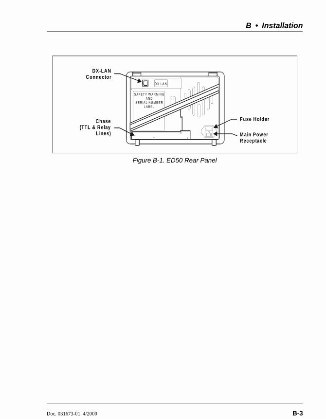
B • Installation
Doc. 031673-01 4/2000 B-3
Figure B-1. ED50 Rear Panel
D X -LA N
DX-LAN Connector
Fuse Holder
M ain PowerReceptacle
Chase(TTL & Relay
Lines)
S A F E TY W A R N IN GA N D
S E R IA L N U M B E RL A B E L
ED50 Electrochemical Detector
B-4 Doc. 031673-01 4/2000
B.2.2 DX-LAN Interface: 10BASE-T Connections (Optional)
NOTE There are two types of DX-LAN connectors. Before proceeding, check the ED50 rear panel. If a DX-LAN 10BASE-T RJ-45 (telephone-style) connector is installed, follow the interface instructions in Section B.2.2. However, if a DX-LAN 10BASE-2 BNC connector is installed, follow the interface instructions in Section B.2.3.
In order to communicate with a host computer running Dionex chromatography software, the ED50 must contain a detector interface card (P/N 056798) and an unshielded twisted-pair DX-LAN cable (P/N 960281) must be connected from the RJ-45 (10BASE-T) connector on the rear panel to a “combo” 10BASE-T Ethernet hub (P/N 056909).
Installing or Replacing the Detector Interface Card
NOTE If the DX-LAN option was not installed at the factory, order the detector interface card kit (P/N 057007). The kit includes all the components required for DX-LAN communication.
1. To replace an existing detector interface card, remove the DX-LAN cable from the 10BASE-T connector on the ED50 rear panel (see Figure B-1).
2. Remove any TTL/Relay plugs from the connectors at slot 4 of the electronics chassis (see Figure 2-5).
STATIC—The ED50 electronics cannot be serviced by the user. The detector interface card must be installed by qualified personnel. Standard anti-static procedures must be observed when installing the interface card or handling the CPU card.
To prevent damage to the ED50, turn off the main power before installing the detector interface card. After confirming that the LED on the CPU card is off (not green or red), unplug the power. Do not rely on the front panel power switch.

B • Installation
Doc. 031673-01 4/2000 B-5
3. Disconnect the 60-pin ribbon cable from the inside of the front panel by opening the ejector latches on the connector.
4. Using a screwdriver as a lever, open the white ejector latch at the bottom of the CPU card. Remove the CPU card, cable, and Relay card as a single unit.
5. Remove the detector interface card (if present) from slot 4 of the electronics chassis.
6. Insert the new detector interface card (P/N 056798) into slot 4:
a. Slide the card to the rear.
b. Verify that the 10BASE-T connector is aligned with the opening at the rear and that the card is aligned with the card connector.
c. Press firmly on the card until it mates fully with the connector on the rear panel. Pull on the card to verify that it cannot move.
7. Reinstall the CPU/Relay card. Press firmly until the card is inserted into the connector on the rear panel.
8. Reconnect the ribbon cable to the 60-pin connector on the inside of the front panel. The header and connector are key-polarized near the center. The ejector latches should be partially open to accept the cable connector.
9. Install the 10BASE-T DX-LAN cable (see the following section).
Installing the 10BASE-T DX-LAN Cable
1. Install the “combo” 10BASE-T Ethernet hub (P/N 056909) on a workbench or on the wall. For installation instructions and site requirements, refer to the installation guide shipped with the hub.
2. Plug the 10BASE-T DX-LAN cable (P/N 960281) into a 10BASE-T port on the front panel of the hub.
3. Connect the other end of the cable into the 10BASE-T DX-LAN connector on the ED50 rear panel (see Figure B-1).
The 10BASE-T DX-LAN cable is a Category 5 unshielded twisted-pair cable. Do not substitute a cable of an inferior grade. Failure to use the correct cable will cause the detector to lose communication with the host computer.

ED50 Electrochemical Detector
B-6 Doc. 031673-01 4/2000
4. Connect a 10BASE-T cable (P/N 960281) from a 10BASE-T port on the hub to the 10BASE-T port on the host computer’s internal DX-LAN card. If the connection is via port 8 on the hub, set the Normal/Uplink push button to Normal.
NOTE Installation instructions for the host computer’s internal DX-LAN card are in Installing the Dionex PeakNet 6 System (Document No. 031631).
Network Upgrades
If you upgrade the network from a BNC connector to a 10BASE-T connector, turn off the computer power briefly and then turn it on again to allow the host computer’s internal Ethernet DX-LAN card to detect the 10BASE-T connector. The Ethernet card searches for the type of installed cabling only at power-up.
Cascading Hubs
Cascading, or connecting hubs together through their 10BASE-T ports, increases the number of ports or the number of users supported on the network. For instructions, refer to the installation guide for the hub.
When using 10BASE-T cabling, you must use a hub. If you simply plug the 10BASE-T cable from the detector into the connector on the host computer’s DX-LAN card, the connection will either not work or will be unreliable.
B • Installation
Doc. 031673-01 4/2000 B-7
B.2.3 DX-LAN Interface: BNC Connections (Optional)
NOTE There are two types of DX-LAN connectors. Before proceeding, check the ED50 rear panel. If a DX-LAN 10BASE-2 BNC connector is installed, follow the interface instructions in Section B.2.3. However, if a DX-LAN 10BASE-T RJ-45 (telephone-style) connector is installed, follow the instructions in Section B.2.2.
In order to communicate with a host computer running Dionex chromatography software, the ED50 must contain a detector interface card (P/N 046341) and a coaxial DX-LAN cable (P/N 960405) must be connected to the BNC tee connector (P/N 921914) on the rear panel. From the ED50, connect the DX-LAN cable to one of the following:
Another instrument equipped with a BNC connector, or
A “combo” 10BASE-T Ethernet hub (P/N 056909). The hub has one BNC port and eight 10BASE-T (RJ-45) ports.
Installing or Replacing the Detector Interface Card
NOTE If the DX-LAN option was not installed at the factory, order the detector interface card kit (P/N 044195). The kit includes the components required for DX-LAN communication.
1. To replace an existing detector interface card, remove the hex nut securing the DX-LAN BNC connector to the ED50 rear panel (see Figure B-1).
STATIC—The ED50 electronics cannot be serviced by the user. The detector interface card must be installed by qualified personnel. Standard anti-static procedures must be observed when installing the interface card or handling the CPU card.
To prevent damage to the ED50, turn off the main power before installing the detector interface card. After confirming that the LED on the CPU card is off (not green or red), unplug the power. Do not rely on the front panel power switch.

ED50 Electrochemical Detector
B-8 Doc. 031673-01 4/2000
2. Remove any TTL/Relay plugs from the connectors at slot 4 of the electronics chassis (see Figure 2-5).
3. Disconnect the 60-pin ribbon cable from the inside of the front panel by opening the ejector latches on the connector.
4. Using a screwdriver as a lever, open the white ejector latch at the bottom of the CPU card. Remove the CPU card, cable, and Relay card as a single unit.
5. Remove the detector interface card (if present) from slot 4 of the electronics chassis.
6. Insert the new detector interface card (P/N 046341) into slot 4:
a. Slide the card to the rear.
b. Verify that the BNC connector is aligned with the opening at the rear and that the card is aligned with the card connector.
c. Press firmly on the card until it mates fully with the connector on the rear panel. Pull on the card to verify that it cannot move.
7. Reinstall the CPU/Relay card. Press firmly until the card is inserted into the connector on the rear panel.
8. Reconnect the ribbon cable to the 60-pin connector on the inside of the front panel. The header and connector are key-polarized near the center. The ejector latches must be partially open to accept the cable connector.
9. Install the hex nut, BNC tee connector, and coaxial DX-LAN cable (see the following section).
Installing the BNC Tee Connector and Coaxial DX-LAN Cable
1. Install the BNC tee connector (P/N 921914):
a. Note the two small locking pins on either side of the DX-LAN BNC connector on the rear panel (see Figure B-1).
b. Push the tee connector onto the BNC connector on the rear panel and twist until the locking pins are fully engaged in the slots on the tee connector.
c. Pull firmly on the tee connector to verify that it cannot move.
2. Install the coaxial DX-LAN cable (P/N 960405):
B • Installation
Doc. 031673-01 4/2000 B-9
a. Push the metal sleeve on the end of the DX-LAN cable onto one port of the BNC tee connector.
b. Twist the metal sleeve until the locking pins on the tee are fully engaged in the slots on the cable's metal sleeve.
c. Pull the end of the cable to verify that it cannot move.
3. If the ED50 is the last module in the network to be connected, install a terminator resistor plug (P/N 921034) on the remaining port of the BNC tee connector. (These terminator resistor plugs are shipped with Dionex chromatography software.)
If the ED50 is not the last module in the network, connect the cable from the next module to the BNC tee.
4. Plug the free end of the coaxial DX-LAN cable into one of these:
The BNC connector on another instrument, or
The BNC port on the rear panel of the “combo” 10BASE-T Ethernet hub (P/N 056909).
If the connection terminates at the hub, install a BNC terminator (included with the hub) on the BNC tee connector.
The DX-LAN cable (P/N 960405) is a 50 ohm coaxial impedance cable. (Fifty ohm cables are imprinted with “RG-58U.”) Do not substitute cables. Failure to use the correct cable or to lock it into place on the BNC connector will cause the ED50 to lose communication with the host computer.
50 Ohm terminator resistor plugs must be installed at each end of the DX-LAN network. Before beginning operation, verify that both ends of the DX-LAN have terminator resistor plugs installed.

ED50 Electrochemical Detector
B-10 Doc. 031673-01 4/2000
B.2.4 DS3 Detection Stabilizer Installation
Install the DS3 with the conductivity cell (P/N 044130) in a chromatography module—for example, an LC20 Chromatography Enclosure—or on a laboratory workbench. The instructions for installing the DS3 vary somewhat, depending on the type of enclosure. See Section B.2.6 for installation and plumbing instructions.
NOTE To install a DS3 or shielded cell in an AS50autosampler chromatography compartment oroven, refer to the AS50 operator’s manual.
B.2.5 Shielded Conductivity Cell Installation
The installation instructions for the shielded conductivity cell (P/N 044132) are the same as for the DS3, except that the shielded cell does not have a heater power cord.
B.2.6 DS3 or Shielded Cell Plumbing
The DS3 or shielded cell can be plumbed for three operating modes:
AutoSuppression™ Recycle mode (SRS required), shown in Figure B-2.
AutoSuppression with External Regenerant mode (SRS required), shown in Figure B-3. Also plumb the system in this way for the AutoSuppression Chemical Suppressor and MMS Pressurized Regen System configurations.
Nonsuppressed mode, shown in Figure B-4. Note that conductivity measurements made when no suppressor is in-line may show noticeable baseline drift.

B • Installation
Doc. 031673-01 4/2000 B-11
The ED50 Ship Kit includes certain items required when installing the SRS:
SRS gas separator waste tube (P/N 045460)
Backpressure coil for 4 mm SRS (P/N 045877)
SRS-to-ED50/ED50 control cable (P/N 046346)
NOTE The instructions here do not replace the instructionsin your SRS manual. For detailed SRS installationinstructions, and for the initial start-up procedurethat must be performed before you begin routineoperation, please refer to the SRS manual.
Backpressure Requirements
Detector cells require enough backpressure to prevent mobile phase in the cell from degassing due to abrupt volume changes between the small inner diameter of the connecting tubing and the larger volume of the cell. Degassing creates bubbles in the cell and disrupts detector responsiveness.
Before plumbing a system for the AutoSuppression mode, check the SRS manual for backpressure requirements.
NOTE The backpressure generated by the DS3, cell, andbackpressure tubing is applied to the SRS. Forexample, with 1 meter of 0.25-mm (0.01-in) IDtubing at a flow rate of 1.0 mL/min, thebackpressure is about 200 kPa (30 psi).

ED50 Electrochemical Detector
B-12 Doc. 031673-01 4/2000
For backpressure requirements for the Nonsuppressed mode, see the following table. The minimum backpressure should be 0.21 to 0.34 MPa (30 to 50 psi) per minute.
Table B-1. Coils for Backpressure Requirements (Nonsuppressed Mode)
Flow Rate (mL/min) Tubing ID Coil Length Number of Coils
0.5 to 1.5 0.25-cm (0.010-in)
0.76 M (2.5 feet)
2
1.5 to 3.0 0.25-cm (0.010-in)
0.76 M (2.5 feet)
1
0.12 to 0.37 0.12-cm (0.005-in)
0.30 M (1.0 feet)
2
0.37 to 0.75 0.12-cm (0.005-in)
0.30 M (1.0 feet)
1
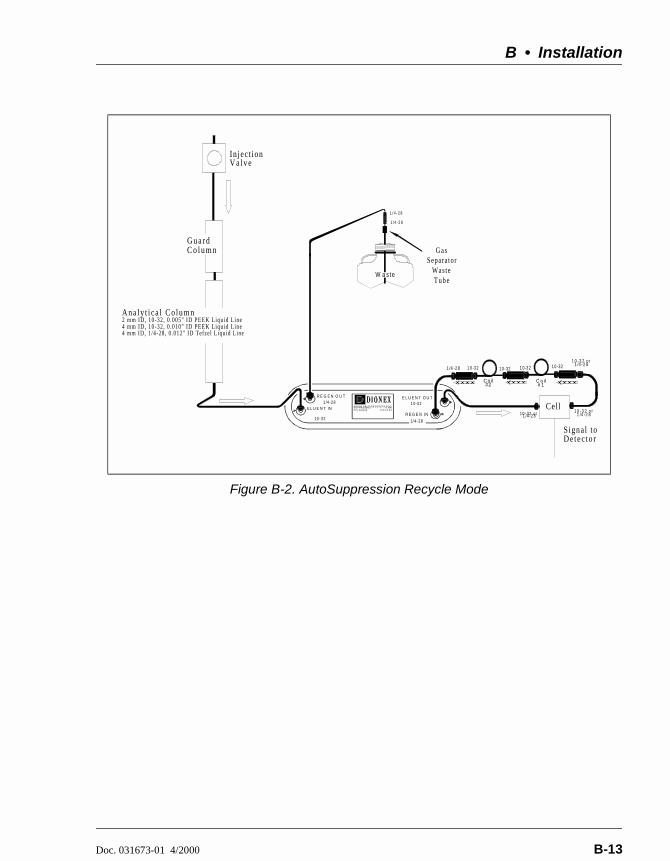
B • Installation
Doc. 031673-01 4/2000 B-13
Figure B-2. AutoSuppression Recycle Mode
10 -3 2
1 /4-2 8R E G E N O U T
E L U E N T IN1 0-3 2
1/4- 28
E L U E N T OU T
R E GE N I N1 0 -3 2 or 1 /4 -2 8
In jec t ion V a l v e
1 0 - 32 or 1 /4 -2 8
Signal toDe tec to r
1 0 -321 0-3 21 0 -32
Coi l#2
C oi l# 1
1 0 -3 21 /4 -2 81 0 -3 2 or 1 /4 -2 8
CellA N I ON S E L F - R E GE N E R A T I NGS U P P R E S S OR 4 mmP /N 04 3 1 89 S /N X X X X
G u a r dC o l u m n
Ana ly t i ca l Co lumn2 mm ID, 10-32, 0 .005" ID PEEK Liquid Line4 mm ID, 10-32, 0 .010" ID PEEK Liquid Line4 mm ID, 1/4-28, 0.012" ID Tefzel Liquid Line
1 /4 - 2 8
1 /4 - 2 8
G a sSepara tor
Was te T u b e
W as te

ED50 Electrochemical Detector
B-14 Doc. 031673-01 4/2000
Figure B-3. AutoSuppression Mode, External Regenerant
Figure B-4. Nonsuppressed Mode
10-32
10-32
10-32
C o i l# 2
C oi l# 1
1/4-28
10-32
10 -3 2 or 1 /4 -2 8
1 0-32
1/4 -2 8R E G E N O U T
A N IO N S E L F -R E G E N E R A T I N GS U P P R E S S O R 4 m mP /N X X X X X X S /N X X X XE L UE N T IN
10-32
1 /4 -28
E L U E N T O U T
R E G E N IN
In jec tio n Va lv e
1 0-32 or 1 /4 -2 8
S ig n a l toC o n d u c tiv ityD e tec to r
10 -32 or 1 / 4-2 8
D e io n izedW ate r S o u rce
To W as te
0 .02 0" ID T efz e l
C ell
G u ardC o lu m n
1/4-28
1 /4-28
G a sS e p a ra to r
W a ste T u b eW aste
A n aly tica l C o lu m n2 m m ID , 1 0 -3 2 , 0 .0 0 5 " ID P E E K L iq u id L in e4 m m ID , 1 0 - 3 2 , 0 .0 1 0 " ID P E E K L iq u id L in e4 m m ID , 1 /4 -2 8 , 0 .0 1 2 " ID T e fz e l L iq u id L in e
DS3
Injection Valve Guard
Column
Analytical Column2 m m ID , 10 -32 , 0 .0 0 5" ID P E E K L iq u id L in e4 m m ID , 1 0 -32 , 0 .0 10 " ID P E E K L iq u id L in e4 m m ID , 1 /4 -2 8 , 0 .0 1 2 " ID Tefze l L iqu id L ine
Backpressure Coils
ToWaste

B • Installation
Doc. 031673-01 4/2000 B-15
Figure B-5. Typical DS3 Installation in LC20 or LC30
SRSDS3 Detection Stabilizer(or ShieldedConductivity Cell)
Alternate DS3 orShielded Conductivity CellLocation
FRONT

ED50 Electrochemical Detector
B-16 Doc. 031673-01 4/2000
Installing a DS3 or Shielded Cell in an LC20, LC25, or LC30
1. Position the keyhole slots on the rear of the DS3 or cell over the shoulder washers on the LC20, LC25, or LC30 component mounting panel, then pull the DS3 or cell down into position.
2. Route the DS3 or cell cables out the hole located at the back of the LC20, LC25, or LC30 and into the cable chase at the base of the detector. Next, route the cables through the cable chase to the front of the detector. (You can also route the cables into the detector through the slots on the sides of the detector.)
3. Plug the connectors on the cables into the appropriate jacks on the SCR card. (To identify the card location and connector positions, see the label on the inside of the ED50 front door or to Figure 2-5 in this manual.)
4. Connect the eluent outlet of the column or suppressor to the DS3 or cell inlet, using 0.25-mm (0.010-in) ID tubing (P/N 042690), 10-32 fittings (P/N 043275), and ferrules (P/N 043276).
5. Connect the outlet of the DS3 or cell to either the SRS REGEN IN port (for AutoSuppression Recycle mode) or to the backpressure line leading to waste (for AutoSuppression with External Regenerant mode or Nonsuppressed mode).
6. Direct the spill/overflow tubing to the spill tray at the bottom front of the LC20, LC25, or LC30.
Installing a DS3 or Shielded Cell in an LC10
1. If installing a DS3, cut the spill/overflow tubing within 2.0 cm (3/4 in) of the DS3 enclosure.
2. Position the keyhole slots on the rear of the DS3 or cell over the shoulder washers located on the LC10. Push the DS3 or cell down to secure it in place.
3. Route both DS3 or cell cables through the hole located at the base of the detector cable chase. Next, route the cables through the cable chase to the front of the detector. (You can also route the cables into the detector using the slots on the sides of the detector.)

B • Installation
Doc. 031673-01 4/2000 B-17
4. Plug the connectors into the appropriate jacks on the SCR card. (To identify the card location and connector positions, see the label on the inside of the ED50 front door or to Figure 2-5 in this manual.)
5. Connect the eluent outlet of the column or suppressor to the DS3 or cell inlet, using 0.25-mm (0.010-in) ID PEEK tubing (P/N 042690), 10-32 fittings (P/N 043275), and ferrules (P/N 043276). See Table B-1 for backpressure requirements.
6. Connect the outlet of the DS3 or cell (the 10-32 coupler) to the SRS REGEN IN port (for AutoSuppression Recycle mode) or to the backpressure line leading to waste (for AutoSuppression with External Regenerant mode or Nonsuppressed mode).

ED50 Electrochemical Detector
B-18 Doc. 031673-01 4/2000
B.2.7 Amperometry Cell Installation
Install the ED50 amperometry cell directly after the column. (A suppressor is not typically used with the amperometry cell.) Figure B-6 shows the plumbing schematic for amperometry detection.
A second detector (an AD25 Absorbance Detector, for example) may be installed before the amperometry cell. However, if a second detector is installed after the cell, make sure the pressure at the amperometry cell outlet remains below 700 kPa (100 psi). Because of the volume within the reference electrode section of the cell, you may note some band broadening at the second detector. However, this is minimized by the precision flat bottomed reference electrode.
Figure B-6. Amperometry Cell Plumbing Schematic
AnalyticalColum n
Am perom etryCell
Waste LineTo Waste Container
To Detector'sConnectorCell Cable
Cell O utlet
Cell Inlet
Union
G uardColum n
Note:Route the cell cable and w aste line through the service chase on the rightside of the com partm ent.
From Pum p
Sam ple Loop
From AS50 Inject Port
To AS50 Drip Tray
Injection Valve
1 2
436
5
B • Installation
Doc. 031673-01 4/2000 B-19
1. Inspect the cell gasket; if it is scratched or damaged, replace the gasket (P/N 045972).
2. Rinse the gasket with deionized water. Clean the polished surface of the cell with a damp paper towel.
3. Install the gasket over the alignment studs on the cell body. When correctly installed, one end of the gasket extends beyond the cell body, to facilitate gasket installation and removal.
4. Polish the working electrode block (see Section 5.5) and rinse its surface with deionized water. Wipe it with a damp paper towel.
NOTE Polishing the working electrode is recommended
only before initial installation and if the electrodeever becomes seriously fouled.
5. Install the polished working electrode block over the alignment studs so that the electrode type stamped on the top of the working electrode faces up.
6. Fasten the working electrode in place with the wing screws (P/N 045937). The electrode material stamped on the block is visible with the cover on.
7. Remove the pH reference electrode (P/N 046333) from its box within the amperometry cell shipping container. Remove the electrode from the soaker bottle in which it is shipped by partially unscrewing the lid of the soaker bottle and pulling the electrode out of the O-ring groove within the lid.
8. Rinse the reference electrode thoroughly in deionized water to remove any precipitated salt. Do not discard the soaker bottle and lid; they are required for safe storage of the electrode when the amperometry cell is not in use.
9. Following the instructions on the pH CALIBRATION screen, calibrate the reference electrode.
10. To install the calibrated electrode, remove the reference electrode compression nut (P/N 045968) from the cell body.

ED50 Electrochemical Detector
B-20 Doc. 031673-01 4/2000
11. Fill the reference electrode cavity within the cell body with enough deionized water to saturate the O-ring within the reference electrode cavity.
12. Feed the reference electrode cable (P/N 045868) through the slot in the compression nut. Carefully guide the reference electrode with the nut into the reference electrode cavity. After making sure the electrode is properly aligned, screw the compression nut into the cell body until it completely bottoms out. If the electrode is not aligned when you tighten the compression nut, the side of the electrode may crack. As you tighten the compression nut, the reference electrode will slip into position past the O-ring.
13. Connect the reference electrode cable to Junction J2 on the cell pre-amp PC board.
14. Verify that the white working electrode lead wire is connected to junction J1 on the cell pre-amp PC board.
15. Slide the cell cover back over the cell body and tighten the cell cover thumbscrew.
16. Make sure the detector cell is turned off. Connect the amperometry cell cable to connector #1 on the SP card. (For an illustration of card locations, see Figure 2-2 in this manual or refer to the label on the inside of the front door.)
a. If the chromatography module is an LC20 or LC30, feed the amperometry cell cable either under the card cage and out the back of the detector, or directly out the side of the detector. Connect the cable to the amperometry cell, allowing a service loop to slide the chromatography component card in and out of the module.
b. If the chromatography module is an LC10, first remove the amperometry cell insulation plate (P/N 046617), cell mounting screws (P/N 045796), and cell mounting washers (P/N 045973) from the cell body. Store these components in a safe place; they are necessary insulation and mounting components for the LC20 and LC30 if the system is later upgraded. Connect the amperometry cell cable to the amperometry cell.
c. To install the cell outside the chromatography module, use the amperometry cell bracket (P/N 048749). Locate the bracket as

B • Installation
Doc. 031673-01 4/2000 B-21
close as possible to the column outlet, to minimize dead volume. When properly installed, the amperometry cell hangs on the bracket at an angle that minimize bubble formation.
17. Attach the tubing from the column to the cell inlet.
NOTE The short length of titanium tubing at the cell inletis an integral part of the cell. DO NOT REMOVEIT. This tube extends the counterelectrode, therebyshielding the working electrode from electricalnoise.
18. Connect the waste line to the cell outlet.
19. Secure the plumbed amperometry cell to its appropriate mounting location in the chromatography module.
NOTE When properly mounted, the outlet fitting on theamperometry cell is on the uppermost surface of thecell. This ensures proper orientation of the referenceelectrode within the amperometry cell and helpssweep out bubbles.
B.2.8 Recorder/Diagnostic Connection
Connecting a strip chart recorder or integrator to the ED50 allows you to record or monitor several parameters, in addition to the cell analog output. For a list of the pinouts for the cable, see Appendix F.
Use the twisted black and red wires (P/N 043598) provided in the ED50 Ship Kit (P/N 046297) to connect a recorder or integrator to the SCR card. (For an illustration of card locations, see Figure 2-2 in this manual or refer to the label on the inside of the front door.)
Strip the ends of the wires and insert into the plugs. The signal wire (red) goes on top and the ground wire (black) goes on the bottom of each plug. Use the screwdriver (P/N 046985) provided in the ED50 Ship Kit to tighten the locking screws.
ED50 Electrochemical Detector
B-22 Doc. 031673-01 4/2000
B.3 Automatic SRS Power ControlTTL connections can be used to automatically switch off the power to a Self-Regenerating Suppressor (SRS) when the flow from the pump stops.
1. On the PUMP OPTIONS screen, set TTL2 OUTPUT USAGE to 0 Flow. (For more details, see the operator's manual for the pump.)
2. On the ED50 TTL FUNCTION IN screen, assign TTL3 to SRS OFF/ON.
3. Locate the twisted black and red wires (P/N 043598) and two green TTL connector plugs (P/N 921019) provided in the ED50 Ship Kit.
4. Strip the ends of the wires and insert them into the plugs, with the signal wire (red) on top of each plug and the ground wire (black) on the bottom. Tighten the locking screws with the screwdriver (P/N 046985) provided in the ED50 Ship Kit.
5. Plug one end of the cable into TTL2 OUT on the pump.
6. Route the cable through the upper chase of the pump and the ED50, and then plug the free end of the cable into TTL3 IN on the ED50 Figure B-7.
7. Turn off the flow (from the pump) and confirm that the detector automatically turns off the SRS. First, however, expect a 5-minute delay from the time the ED50 receives the signal until the power to the SRS is turned off; this delay allows momentary flow interruptions without disturbing the SRS.
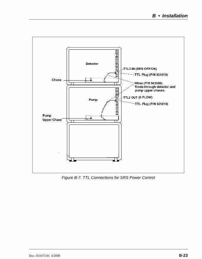
B • Installation
Doc. 031673-01 4/2000 B-23
Figure B-7. TTL Connections for SRS Power Control

ED50 Electrochemical Detector
B-24 Doc. 031673-01 4/2000

Doc. 031673-01 4/2000 C-1
C • User Interface
This appendix illustrates and describes all of the screens available for display on the front panel of the ED50 Electrochemical Detector. There are two categories of screens: operational and diagnostic (see Figure C-1).
Operational screens enable you to create, edit, and run methods that control ED50 operation, and to select default parameters for the detector.
Diagnostic screens provide access to diagnostic information and tests, including some screens that enable you to calibrate various ED50 functions.
Operational screens are selected from the MENU of SCREENS. Diagnostic screens are selected from the DIAGNOSTIC MENU, an option on the MENU of SCREENS.
The detection mode is selected from the MAIN or DETAIL screen. The MENU of SCREENS, the MAIN screen, the DETAIL screen, the METHOD screen, and the WAVEFORM screen are unique to each of the detection modes. The remaining screens are common to all detection modes.
Figure C-1. ED50 Menu Structure
MENU of SCREENS
P O W E R - U PSCREEN
ELAPSEDTIME
DX LANSTATUS
KEYBOARDTEST
DETAILSCREEN
METHODEXTENSION
TIMEFUNCTION IN
MAINSCREEN
DIAGNOSTICMENU
1 2 3 5 6 7 8
1 2 3 5 6 7 8
4
Operational Screens
Diagnostic Screens
MODULESETUPW A V E F O R M
ANALOG OUT SETUP
ANALOGSTATUS
4
DIAGNOSTIC TESTS
SIGNALSTATISTICS
CALIBRATE CD CELL
pHCALIBRATION
9
LEAK CAL& STATUS
10
METHOD

ED50 Electrochemical Detector
C-2 Doc. 031673-01 4/2000
C.1 Operational Screens
C.1.1 Menu of Screens—Conductivity
The MENU of SCREENS provides top-level access to the menu structure.
There are two ways to select a screen from this menu:
Use the cursor directional buttons to move the cursor to the field containing the screen number and press Enter.
Press the number button on the front panel keypad that corresponds to the screen.
To display a brief description of each menu, press the Help button.
Figure C-2. Menu of Screens—Conductivity
Help Message
M AIN SCREENDETAIL SCREENM ETHOD- - -
MODULE SETUPANALOG OUT SETUPTIME FUNCTION INDIAGNOSTIC MENU
1234
5678
M ENU of SCREENS
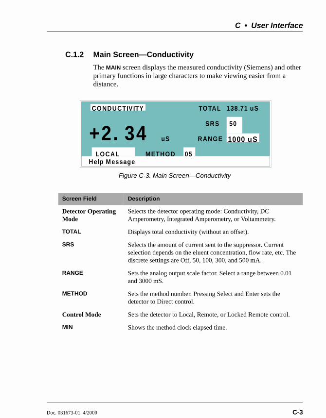
C • User Interface
Doc. 031673-01 4/2000 C-3
C.1.2 Main Screen—Conductivity
The MAIN screen displays the measured conductivity (Siemens) and other primary functions in large characters to make viewing easier from a distance.
Figure C-3. Main Screen—Conductivity
Screen Field Description
Detector Operating Mode
Selects the detector operating mode: Conductivity, DC Amperometry, Integrated Amperometry, or Voltammetry.
TOTAL Displays total conductivity (without an offset).
SRS Selects the amount of current sent to the suppressor. Current selection depends on the eluent concentration, flow rate, etc. The discrete settings are Off, 50, 100, 300, and 500 mA.
RANGE Sets the analog output scale factor. Select a range between 0.01 and 3000 mS.
METHOD Sets the method number. Pressing Select and Enter sets the detector to Direct control.
Control Mode Sets the detector to Local, Remote, or Locked Remote control.
MIN Shows the method clock elapsed time.
Help Message
TOTAL 138.71 uS
SRS
RANGE
50
1000 uS
LOCAL METHOD 05
uS+2. 34CONDUCTIVITY

ED50 Electrochemical Detector
C-4 Doc. 031673-01 4/2000
C.1.3 Detail Screen—Conductivity
The DETAIL screen includes all the fields contained on the MAIN screen, as well as the TTL and Relay fields and fields to control detection. Refer to the MAIN screen for a description of fields that are common to both screens.
Figure C-4. Detail Screen—Conductivity
Screen Field Description
OUTPUT Displays the conductivity, corrected by the offset.
OFFSET Displays the conductivity value used to correct the output. The conductivity can be offset by pressing the front panel button or by programming the command into a Method.
TEMP COMP Sets the temperature compensation factor. The range is 0 to 3%. 1.7% is appropriate for most eluents.
DS3 SETPOINT Sets the temperature of the DS3 Detection Stabilizer.
TTL1
TTL2Provides TTL control of accessories. In a method, these values occur according to the method timing. In Direct control, select off (0) or on (1).
RLY1
RLY2Provides relay contact closure control of accessories. In a method, these values occur according to the method timing. In Direct control, select off (0) or on (1).
Help Message
TOTAL 138.71 uSTEMP COM P
123.45 M INLOCAL M ETHOD 05
DETAIL SCREENOUTPUTOFFSET 115.03
uSuS
TTL1TTL2RLY1RLY2
0
0
11
DS3 SETPOINT 254 C
RANGE1.9
23.68CONDUCTIVITY
200 uS
100 m ASRS

C • User Interface
Doc. 031673-01 4/2000 C-5
C.1.4 Method—Conductivity
A method consists of a series of timed steps. Each step has a set of parameters associated with it.
Initial conditions are applied when a method is invoked. A lower case v next to the last step on the display indicates that the method contains more steps.
Blank fields denote no change from the previous step. The Delete button blanks the field.
NOTE TEMP COMP, DS3 TEMP, and SRS CURRENT are nottime-programmable.
Figure C-5. Method Screen—Conductivity
Screen Field Description
Detector Operating Mode
Selects the detector operating mode: Conductivity, DC Amperometry, or Integrated Amperometry.
EDIT Specifies the method number (0 through 99) to edit.
SAVE TO Specifies the method number (0 through 99) to save the current method to.
RUN Specifies the method number (0 through 99) to run. The Hold/Run button controls the running of the method.
TEMP COMP Sets the Temperature Compensation factor.
SET TEMP Sets the temperature for the DS3 Detection Stabilizer.
SRS Sets the Self-Regenerating Suppressor current.
Help Message
1.6TTL RLY
01
1
M ETHOD EDIT SAVE TO RUN 253333
TIM E RANGE 2 1 20 0 0
1
OFFSET M ARKINIT0.00
v* *
2.00
TEM P COM PCOND
200 uS
SRS 100DS3 TEM P 40

ED50 Electrochemical Detector
C-6 Doc. 031673-01 4/2000
TIME Specifies the start time for each step. Times are displayed chronologically.
RANGE Sets the analog output range.
OFFSET Stores the offset value. The baseline is set by subtracting the offset measured when this step is executed from all subsequent measurements. An asterisk (*) indicates that OFFSET will occur at this time.
MARK Sends a positive pulse to the analog output (recorder) as an event marker. An asterisk (*) indicates that a MARK will occur at this time.
TTL Sets TTL1 and TTL2 to off (0) or on (1).
RLY Sets RLY1 and RLY2 to off (0) or on (1).
Screen Field Description

C • User Interface
Doc. 031673-01 4/2000 C-7
C.1.5 Menu of Screens—Integrated Amperometry
Figure C-6 shows the MENU of SCREENS for the Integrated Amperometry mode.
There are two ways to select a screen from this menu:
Use the cursor directional buttons to move the cursor to the field containing the screen number and press Enter.
Press the number button on the front panel keypad that corresponds to the screen.
To display a brief description of each menu, press the Help button.
Figure C-6. Menu of Screens—Integrated Amperometry
Help Message
M AIN SCREENDETAIL SCREENM ETHODWAVEFORM
MODULE SETUPANALOG OUT SETUPTIME FUNCTION INDIAGNOSTIC MENU
1234
5678
MENU of INTEGRATED AM PEROMETRY SCREENS

ED50 Electrochemical Detector
C-8 Doc. 031673-01 4/2000
C.1.6 Main Screen—Integrated Amperometry
The MAIN screen displays the measured charge (coulombs) and other primary functions in large characters to make viewing easier from a distance.
Figure C-7. Main Screen—Integrated Amperometry
Screen Field Description
Detector Operating Mode
Selects the detector operating mode: Conductivity, DC Amperometry, Integrated Amperometry, or Voltammetry.
WAVEFORM Sets the waveform number to run. Program the waveform from the WAVEFORM screen.
CELL Turns the amperometry cell off and on, disabling or enabling detection.
RANGE Sets the detector sensitivity between 50 pC and 200 µC.
METHOD Sets the method number. Pressing Select and Enter sets the detector to Direct control.
Control Mode Sets the detector to Local, Remote, or Locked Remote control.
MIN Shows the waveform clock elapsed time.
Help Message
WAVEFORM
CELL
RANGE
ON
1000 nC
134.56 MINLOCAL METHOD 05
uC- 4.36INT AMPEROMETRY 17
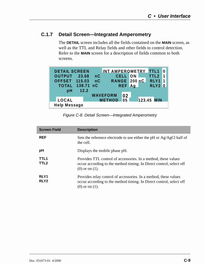
C • User Interface
Doc. 031673-01 4/2000 C-9
C.1.7 Detail Screen—Integrated Amperometry
The DETAIL screen includes all the fields contained on the MAIN screen, as well as the TTL and Relay fields and other fields to control detection. Refer to the MAIN screen for a description of fields common to both screens.
Figure C-8. Detail Screen—Integrated Amperometry
Screen Field Description
REF Sets the reference electrode to use either the pH or Ag/AgCl half of the cell.
pH Displays the mobile phase pH.
TTL1TTL2
Provides TTL control of accessories. In a method, these values occur according to the method timing. In Direct control, select off (0) or on (1).
RLY1RLY2
Provides relay control of accessories. In a method, these values occur according to the method timing. In Direct control, select off (0) or on (1).
Help Message
TOTAL 138.71 nCRANGE
123.45 M INLOCAL M ETHOD 05
DETAIL SCREENOUTPUTOFFSET 115.03
nCnC
TTL1TTL2RLY1RLY2
0
0
11
WAVEFORM 02
CELL 23.68INT AMPEROMETRY
pH 12.2REF
ON200 nCAg

ED50 Electrochemical Detector
C-10 Doc. 031673-01 4/2000
C.1.8 Method—Integrated Amperometry
A method consists of a series of timed steps. Each step has a set of parameters associated with it.
Initial conditions are applied when a method is invoked. A lower case v next to the last step on the display indicates that the method contains more steps.s
Blank fields denote no change from the previous step. The Delete button blanks the field.
Figure C-9. Method Screen—Integrated Amperometry
Screen Field Description
Detector Operating Mode
Selects the detector operating mode: Conductivity, DC Amperometry, or Integrated Amperometry.
EDIT Specifies the method number (0 through 99) to edit.
SAVE TO Specifies the method number (0 through 99) to save the current method to.
RUN Specifies the method number (0 through 99) to run. The Hold/Run button controls the running of the method.
TIME Specifies the start time for each step. Times are displayed chronologically.
WAVE Sets the waveform number (0 through 19) to run.
RANGE Specifies the detection range.
Help Message
TTL RLY
01
1
METHOD EDIT SAVE TO RUN 253333
TIME RANGE 2 1 20 0
1
OFFSET MARKINIT0.00 * *2.00
I AMP
WAVE
4.00
13 200 uC 0
00

C • User Interface
Doc. 031673-01 4/2000 C-11
OFFSET Stores the offset value. The baseline is set by subtracting the offset measured when this step executes from all subsequent measurements. An asterisk (*) indicates that OFFSET will occur at this time.
MARK Sends a positive pulse to the analog output (recorder) as an event marker. An asterisk (*) indicates a MARK will occur at this time.
TTL Sets TTL1 and TTL2 to off (0) or on (1).
RLY Sets RLY1 and RLY2 to off (0) or on (1).
Screen Field Description

ED50 Electrochemical Detector
C-12 Doc. 031673-01 4/2000
C.1.9 Waveform—Integrated Amperometry
Figure C-10 shows the WAVEFORM screen for Integrated Amperometry. These entries form points on a plot of potential vs. time.
When the last step displayed is not the last step in the waveform, a lower case v is displayed beside the time digits in the last line.
Figure C-10. Waveform Screen—Integrated Amperometry
Screen Field Description
WAVE EDIT Specifies the waveform number (0 through 19) to edit.
SAVE TO Specifies the waveform number (0 through 19) to save the current waveform definition to.
RUN Specifies the waveform number (0 through 19) to run.
TIME Specifies the time for this step. Times are displayed chronologically.
POTENTIAL The left field sets the polarity; the right field is the point in the waveform for this voltage. No entry means the values from the preceding step remain in effect.
INTEGRATE Sets the begin and ending times for the integration period. Integration cannot begin on the first waveform step, or end on the last step.
Help Message
EDIT SAVE TO RUN1919INT AM P WAVESTEP TIME (sec) POTEN (V) INTEGRATE01234
0.000.300.500.510.60
+
+-V
0.10
0.600.30
BEGINEND
13

C • User Interface
Doc. 031673-01 4/2000 C-13
C.1.10 Menu of Screens—DC Amperometry
Figure C-11 shows the MENU of SCREENS for the DC Amperometry mode.
There are two ways to select a screen from this menu:
Use the cursor directional buttons to move the cursor to the field containing the screen number and press Enter.
Press the number button on the front panel keypad that corresponds to the screen.
To display a brief description of each menu, press the Help button.
Figure C-11. Menu of Screens Screen—DC Amperometry
Help Message
M AIN SCREENDETAIL SCREENM ETHOD----
MODULE SETUPANALOG OUT SETUPTIME FUNCTION INDIAGNOSTIC MENU
1234
5678
MENU of DC AM PEROMETRY SCREENS

ED50 Electrochemical Detector
C-14 Doc. 031673-01 4/2000
C.1.11 Main Screen—DC Amperometry
The MAIN screen displays the measured current (Amperes) and other primary functions in large characters to make viewing easier from a distance.
Figure C-12. Main Screen—DC Amperometry
Screen Field Description
Detector Operating Mode
Selects the detector operating mode: Conductivity, DC Amperometry, Integrated Amperometry, or Voltammetry.
POTENTIAL The field on the left sets the polarity. The field on the right sets the applied potential.
CELL Turns the amperometry cell off or on, disabling or enabling detection.
RANGE Sets the detector sensitivity between 50 pA to 300 µA.
METHOD Sets the method number. Pressing Select and Enter sets the detector to Direct control.
Control Mode Sets the detector to Local, Remote or Locked Remote control.
MIN Shows the method clock elapsed time.
Help Message
POTENTIAL
CELL
RANGE
ON
1000 nA
34.56 M INLOCAL M ETHOD 05
nA- 6. 13DC AM PEROMETRY - 0.05 V

C • User Interface
Doc. 031673-01 4/2000 C-15
C.1.12 Detail Screen—DC Amperometry
The DETAIL screen includes all the fields contained on the MAIN screen, as well as the TTL and Relay fields and other fields to control detection. Refer to the MAIN screen for a description of fields that are common to both screens.
Figure C-13. Detail Screen—DC Amperometry
Screen Field Description
REF Sets the reference electrode to use either the pH or Ag/AgCl half of the cell.
pH Displays the mobile phase pH.
TTL1
TTL2Provides TTL control of accessories. In a method, these values occur according to the method timing. In Direct control, select off (0) or on (1).
RLY1
RLY2Provides relay contact closure control of accessories. In a method, these values occur according to the method timing. In Direct control, select off (0) or on (1).
Help Message
TOTAL 184.9 nARANGE
123.45 M INLOCAL M ETHOD 05
DETAIL SCREENOUTPUTOFFSET 58.7
nAnA
TTL1TTL2RLY1RLY2
0
0
11
PO TENTIAL
CELL 128.2DC AM PEROMETRY
pH 12.2REF
ON200 nAAg
+ 0.80 V

ED50 Electrochemical Detector
C-16 Doc. 031673-01 4/2000
C.1.13 Method—DC Amperometry
A method consists of a series of timed steps. Each step has a set of parameters associated with it.
Initial conditions are applied when a method is invoked. A lower case v next to the last step on the display indicates that the method contains more steps.
Blank fields denote no change from the previous step. The Delete button blanks the field.
Figure C-14. Method Screen—DC Amperometry
Screen Field Description
Detector Operating Mode
Selects the detector operating mode: Conductivity, DC Amperometry, or Integrated Amperometry.
EDIT Specifies the method number (0 through 99) to edit.
SAVE TO Specifies the method number (0 through 99) to save the current method to.
RUN Specifies the method number (0 through 99) to run. The Hold/Run button controls the running of the method.
TIME Specifies the start time for each step. Times are displayed chronologically.
VOLT Specifies the voltage applied to the cell.
RANGE Specifies the detection range.
Help Message
TTL RLY
01
1
METHOD EDIT SAVE TO RUN 253333
TIME RANGE 2 1 20 0
1
OFFSET MARKINIT0.00 * *2.00
D AM P
VOLT
4.00
200 uA 0-0.10
0 0

C • User Interface
Doc. 031673-01 4/2000 C-17
OFFSET Stores the offset value. The baseline is set by subtracting the offset measured when this step executes from all subsequent measurements. An asterisk (*) indicates that OFFSET will occur at this time.
MARK Sends a positive pulse to the analog output (recorder) as an event marker. An asterisk (*) indicates that a MARK will occur at this time.
TTL Sets TTL1 and TTL2 to off (0) or on (1).
RLY Sets RLY1 and RLY2 to off (0) or on (1).
Screen Field Description
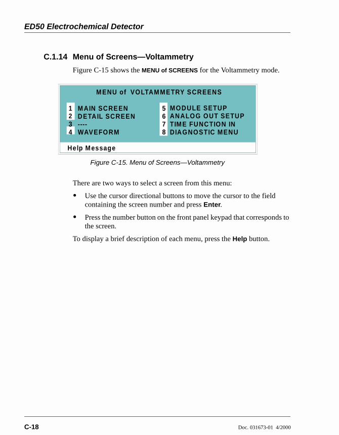
ED50 Electrochemical Detector
C-18 Doc. 031673-01 4/2000
C.1.14 Menu of Screens—Voltammetry
Figure C-15 shows the MENU of SCREENS for the Voltammetry mode.
There are two ways to select a screen from this menu:
Use the cursor directional buttons to move the cursor to the field containing the screen number and press Enter.
Press the number button on the front panel keypad that corresponds to the screen.
To display a brief description of each menu, press the Help button.
Figure C-15. Menu of Screens—Voltammetry
Help Message
M AIN SCREENDETAIL SCREEN----WAVEFORM
MODULE SETUPANALOG OUT SETUPTIME FUNCTION INDIAGNOSTIC MENU
1234
5678
M ENU of VOLTAM METRY SCREENS

C • User Interface
Doc. 031673-01 4/2000 C-19
C.1.15 Main Screen—Voltammetry
The MAIN screen displays the measured current (Amperes) and other primary functions in large characters to make viewing easier from a distance.
Figure C-16. Main Screen—Voltammetry
Screen Field Description
Detector Operating Mode
Selects the detector operating mode: Conductivity, DC Amperometry, Integrated Amperometry, or Voltammetry.
CELL Turns the amperometry cell off or on, disabling or enabling detection.
RANGE Sets the detector sensitivity between 1 nA to 100 µA.
DIRECT CNTRL In Voltammetry mode, the detector is always in Direct control mode. Because methods do not apply to Voltammetry, this field cannot be changed.
Control Mode Sets the detector to Local, Remote, or Locked Remote control.
Help Message
CELL
RANGE
ON
1000 nA
LOCAL
nA- 6. 13VOLTAM METRY
DIRECT CNTRL

ED50 Electrochemical Detector
C-20 Doc. 031673-01 4/2000
C.1.16 Detail Screen — Voltammetry
The DETAIL screen includes all the fields contained on the MAIN screen, as well as the TTL and Relay fields and other fields to control detection. Refer to the MAIN screen for a description of fields that are common to both screens.
Figure C-17. Detail Screen—Voltammetry
Screen Field Description
REF Sets the reference electrode to use either the pH or Ag/AgCl half of the cell.
pH Displays the mobile phase pH.
TTL1
TTL2Provides TTL control of accessories. In a method, these values occur according to the method timing. In Direct control, select off (0) or on (1).
RLY1
RLY2Provides relay control of accessories. Select off (0) or on (1).
Help Message
TOTAL 1.361 uARANGE
LOCAL
DETAIL SCREENOUTPUTOFFSET 1.209
uAuA
TTL1TTL2RLY1RLY2
0
0
11
CELL 0.152VOLTAM METRY
pH 12.2REF
ON200 uAAg
DIRECT CNTRL
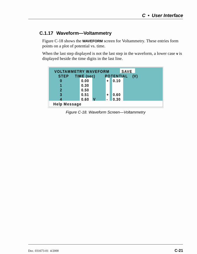
C • User Interface
Doc. 031673-01 4/2000 C-21
C.1.17 Waveform—Voltammetry
Figure C-18 shows the WAVEFORM screen for Voltammetry. These entries form points on a plot of potential vs. time.
When the last step displayed is not the last step in the waveform, a lower case v is displayed beside the time digits in the last line.
Figure C-18. Waveform Screen—Voltammetry
Help Message
STEP TIM E (sec)01234
0.000.300.500.510.60
+
+-V
0.10
0.600.30
VOLTAM M ETRY WAVEFORM SAVEPO TENTIAL (V)

ED50 Electrochemical Detector
C-22 Doc. 031673-01 4/2000
C.1.18 Module Setup
The backlight intensity, key beep, and error beep are configured from the MODULE SETUP screen.
Figure C-19. Module Setup Screen
Screen Field Description
DISPLAY PANEL BACKLIGHT
Sets the display panel backlight to LOW, MEDIUM, HIGH, or OFF.
KEY ACTUATION SOUND
Toggles the keypad touch sound. When this option is on, the detector sounds a beep when a button is pressed.
ENTRY ERROR SOUND
Toggles the error sound. When this option is on, the detector sounds a beep when an invalid entry is made.
Help Message
DISPLAY PANEL BACKLIGHT:KEY ACTUATION SOUND:
ENTRY ERROR SOUND:
MEDIUMONON
MODULE SETUP
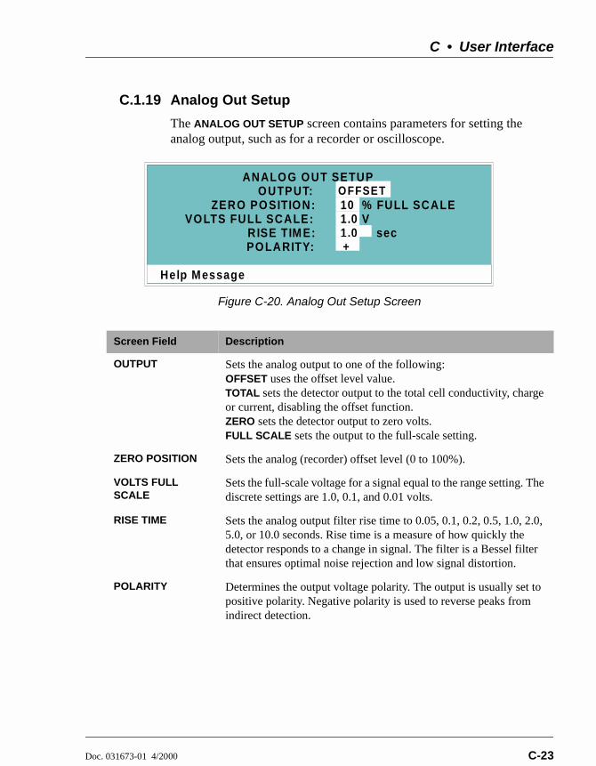
C • User Interface
Doc. 031673-01 4/2000 C-23
C.1.19 Analog Out Setup
The ANALOG OUT SETUP screen contains parameters for setting the analog output, such as for a recorder or oscilloscope.
Figure C-20. Analog Out Setup Screen
Screen Field Description
OUTPUT Sets the analog output to one of the following: OFFSET uses the offset level value. TOTAL sets the detector output to the total cell conductivity, charge or current, disabling the offset function. ZERO sets the detector output to zero volts. FULL SCALE sets the output to the full-scale setting.
ZERO POSITION Sets the analog (recorder) offset level (0 to 100%).
VOLTS FULL SCALE
Sets the full-scale voltage for a signal equal to the range setting. The discrete settings are 1.0, 0.1, and 0.01 volts.
RISE TIME Sets the analog output filter rise time to 0.05, 0.1, 0.2, 0.5, 1.0, 2.0, 5.0, or 10.0 seconds. Rise time is a measure of how quickly the detector responds to a change in signal. The filter is a Bessel filter that ensures optimal noise rejection and low signal distortion.
POLARITY Determines the output voltage polarity. The output is usually set to positive polarity. Negative polarity is used to reverse peaks from indirect detection.
Help Message
VOLTS FULL SCALE:
OFFSETOUTPUT:10
RISE TIM E:POLARITY:
1.01.0+
% FULL SCALEV
sec
ZERO POSITION:
ANALOG OUT SETUP
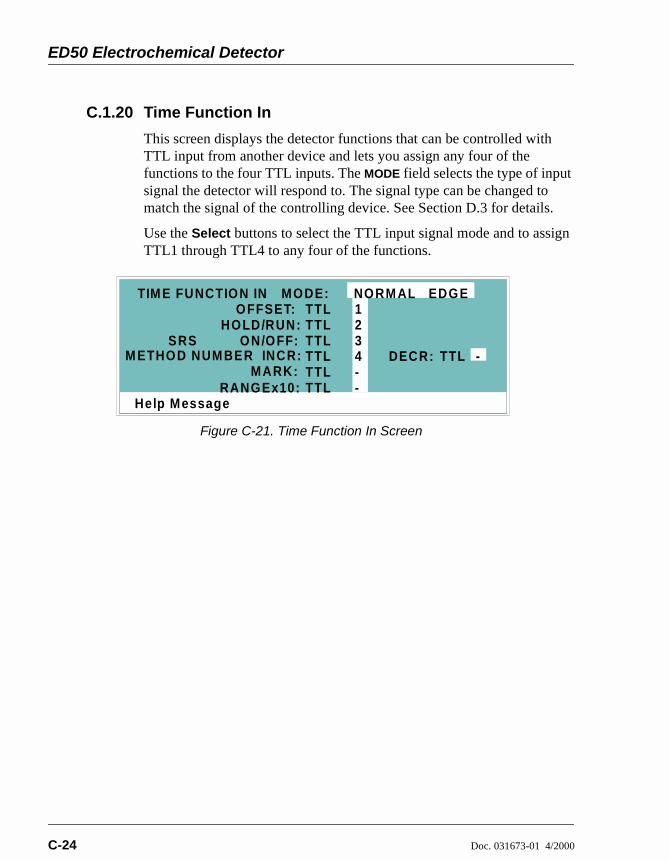
ED50 Electrochemical Detector
C-24 Doc. 031673-01 4/2000
C.1.20 Time Function In
This screen displays the detector functions that can be controlled with TTL input from another device and lets you assign any four of the functions to the four TTL inputs. The MODE field selects the type of input signal the detector will respond to. The signal type can be changed to match the signal of the controlling device. See Section D.3 for details.
Use the Select buttons to select the TTL input signal mode and to assign TTL1 through TTL4 to any four of the functions.
Figure C-21. Time Function In Screen
Help Message
HOLD/RUN:ON/OFF:
1234
TIM E FUNCTION INOFFSET:
MARK:RANGEx10:
MODE: NORM AL EDGE
--
TTLTTLTTLTTLTTLTTL
TTLSRS
M ETHOD NUM BER INCR: DECR: -

C • User Interface
Doc. 031673-01 4/2000 C-25
C.2 Diagnostic ScreensTo access the ED50 diagnostics, select the DIAGNOSTIC MENU from the MENU of SCREENS. While a diagnostic screen is displayed, pressing the Menu button returns you to the DIAGNOSTIC MENU. From the DIAGNOSTIC MENU, pressing Menu returns you to the MENU of SCREENS.
C.2.1 Diagnostic Menu
The DIAGNOSTIC MENU lists the available diagnostic screens. Figure C-22 shows all of the possible menu options; however, the options actually displayed will depend on which detection mode is selected.
Option 7, LEAK CAL(IBRATION) & STATUS, is available only in Conductivity mode and when a leak detector is connected.
Option 9, CALIBRATE CD CELL, is available only in Conductivity mode.
Option 10, pH CALIBRATION, is available only in Integrated Amperometry, DC Amperometry, and Voltammetry modes.
Figure C-22. Diagnostic Menu Screen
Help M essage
POW ER-UP SCREENELAPSED TIM EANALO G STATUS DX- LAN STATUS
DIAGNOSTIC TESTSLEAK CAL & STATUSSIGNAL STATISTICSCALIBRATE CD CELL
12345
678
DIAGNOSTIC MENU
KEYBOARD TEST9
10 pH CALIBRATION

ED50 Electrochemical Detector
C-26 Doc. 031673-01 4/2000
C.2.2 Power-Up Screen
This screen displays the revision numbers for the Moduleware and BIOS code. It also displays the identification number of the optional DX-LAN interface, if connected.
Figure C-23. Power-Up Screen
Help Message
MODULEWARE REV
ED50 ELECTROCHEM ICAL DETECTOR
BIOS REV n.nnn.nn
nnnnnnDX LAN ID#

C • User Interface
Doc. 031673-01 4/2000 C-27
C.2.3 Elapsed Time
This screen reports for how long various ED50 parameters have been in use. The status of each parameter updates in real time.
Figure C-24. Elapsed Time Screen
Screen Field Description
MODULE ON Reports the total time the detector has been powered up in its lifetime.
BACKLIGHT Reports the total time the LCD backlight has been on in its lifetime.
SRS ON Reports the total time the SRS has run. Reset this field to zero after changing the SRS.
EC CELL ON Reports the total time the amperometry cell has run. Reset this field to zero after replacing the cell.
RESET Allows a timer to be reset to zero to restart the counter. Reset the appropriate timer after installing a new component.
Help Message
MO DULE ON:
ELAPSED TIM E
BACKLIGHT:SRS ON:
EC CELL ON:
nnnnnn hoursnnnnnn hoursnnnnnn hoursnnnnnn hours
RESET
**
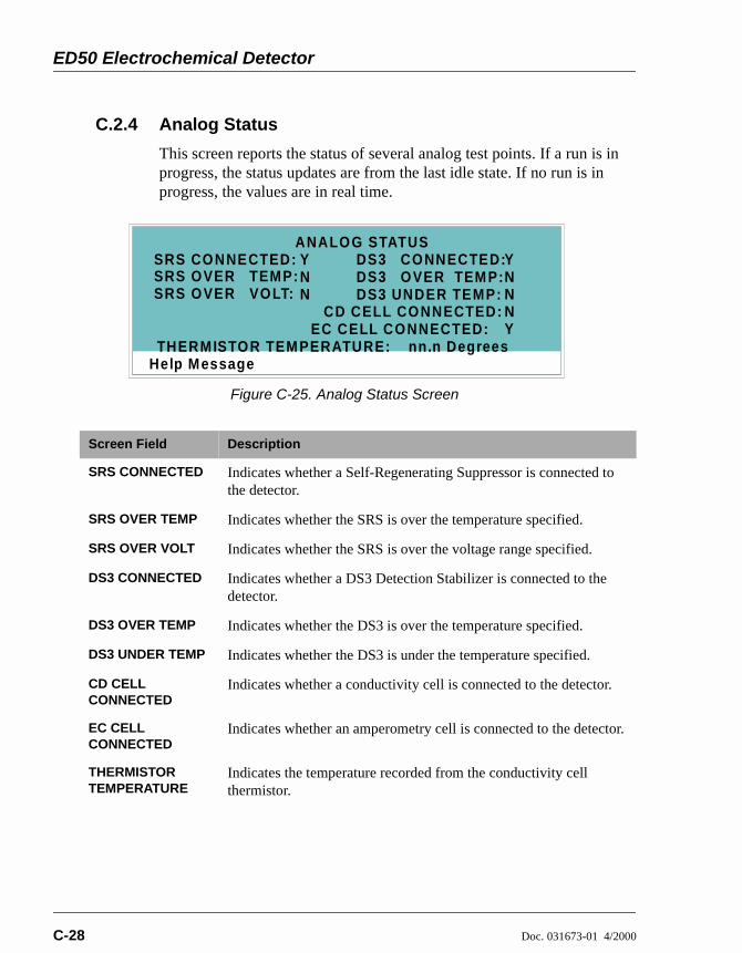
ED50 Electrochemical Detector
C-28 Doc. 031673-01 4/2000
C.2.4 Analog Status
This screen reports the status of several analog test points. If a run is in progress, the status updates are from the last idle state. If no run is in progress, the values are in real time.
Figure C-25. Analog Status Screen
Screen Field Description
SRS CONNECTED Indicates whether a Self-Regenerating Suppressor is connected to the detector.
SRS OVER TEMP Indicates whether the SRS is over the temperature specified.
SRS OVER VOLT Indicates whether the SRS is over the voltage range specified.
DS3 CONNECTED Indicates whether a DS3 Detection Stabilizer is connected to the detector.
DS3 OVER TEMP Indicates whether the DS3 is over the temperature specified.
DS3 UNDER TEMP Indicates whether the DS3 is under the temperature specified.
CD CELL CONNECTED
Indicates whether a conductivity cell is connected to the detector.
EC CELL CONNECTED
Indicates whether an amperometry cell is connected to the detector.
THERMISTOR TEMPERATURE
Indicates the temperature recorded from the conductivity cell thermistor.
Help Message
SRS CONNECTED:ANALOG STATUS
SRS OVER TEMP:SRS OVER VOLT:
DS3 CONNECTED:DS3 OVER TEM P:DS3 UNDER TEMP:
CD CELL CONNECTED:
THERMISTOR TEM PERATURE: nn.n Degrees
YNN
YNNN
EC CELL CONNECTED: Y

C • User Interface
Doc. 031673-01 4/2000 C-29
C.2.5 DX-LAN Status
The DX-LAN driver monitors several types of errors that may occur on the network. The detector reads the DX-LAN error counts and displays them on this screen, along with the DX-LAN addresses. Most errors are caused by a defective cable, missing or incorrectly terminated cable. The DX-LAN cable must be RG58U or RG58AU.
Figure C-26. DX-LAN Status Screen
Screen Field Description
UNIQUE DX-LAN ID Displays the three-byte DX-LAN ID programmed into the detector Moduleware (in HEX). The ID is unique to the detector and never changes.
DX-LAN ADDRESS Displays the six-byte DX-LAN address assigned by the PC (in HEX). The first three bytes are the system assignment and the last three bytes are the assignment within the system.
COLLISION Indicates that 16 unsuccessful transmissions of the same packet occurred, due to collisions.
BUS WRITE Indicates that a ready response could not be issued within 2.4 microseconds after the WR signal was asserted. This occurs when the transmit buffer memory is full.
UNDERFLOW Indicates that data from the transmit section of the hardware buffer memory is not available for serial transmission. The DX-LAN will continue to send out this data frame.
ALIGNMENT Indicates that a packet was received with an alignment error, meaning that there were one to seven extra bits at the end of the packet. This is usually caused by a collision or a faulty transceiver.
Help Message
UNIQUE DX- LAN ID:DX LAN-
-
STATUS
DX LAN ADDRESS:
COLLISION: ALIGNMENT:
UNDERFLOW:BUS W RITE:
nnnnnnnnn
FF FF FF FFFF FF FF FF FF FF
RETRY:
CRC:
OVERFLOW:BUS READ:
nnnnnnnnn
nnnnnnnnn
RUNT:
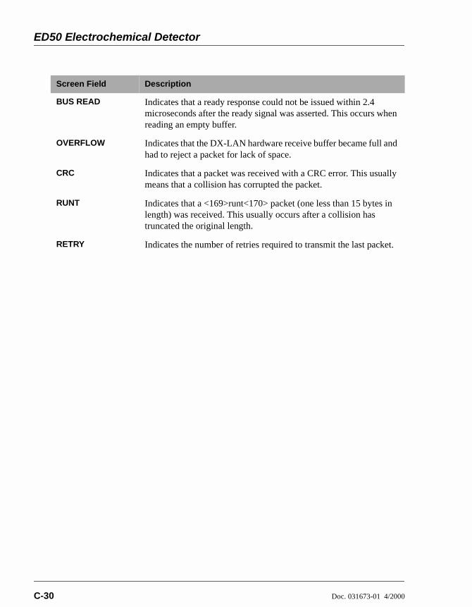
ED50 Electrochemical Detector
C-30 Doc. 031673-01 4/2000
BUS READ Indicates that a ready response could not be issued within 2.4 microseconds after the ready signal was asserted. This occurs when reading an empty buffer.
OVERFLOW Indicates that the DX-LAN hardware receive buffer became full and had to reject a packet for lack of space.
CRC Indicates that a packet was received with a CRC error. This usually means that a collision has corrupted the packet.
RUNT Indicates that a <169>runt<170> packet (one less than 15 bytes in length) was received. This usually occurs after a collision has truncated the original length.
RETRY Indicates the number of retries required to transmit the last packet.
Screen Field Description

C • User Interface
Doc. 031673-01 4/2000 C-31
C.2.6 Keyboard Test
You can conduct an interactive test of the ED50 front panel keypad from this screen. Pressing any front panel button changes the corresponding button indicator on the screen to reverse video. This confirms proper operation of that button. When you release the button, the display returns to normal video.
Figure C-27. Keyboard Test Screen
Help Message
OFFSET
MARK
INSERT
DELETE
RUN/HOLD
RESET
SEL UP
SEL DOW N
UP 7 8 9
4 5 6
1 2 3
0 . E
DOW NLEFT RIGHT
HELP MENU
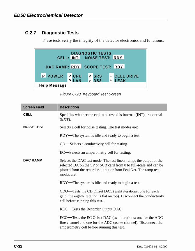
ED50 Electrochemical Detector
C-32 Doc. 031673-01 4/2000
C.2.7 Diagnostic Tests
These tests verify the integrity of the detector electronics and functions.
Figure C-28. Keyboard Test Screen
Screen Field Description
CELL Specifies whether the cell to be tested is internal (INT) or external (EXT).
NOISE TEST Selects a cell for noise testing. The test modes are:
RDY—The system is idle and ready to begin a test.
CD—Selects a conductivity cell for testing.
EC—Selects an amperometry cell for testing.
DAC RAMP Selects the DAC test mode. The test linear ramps the output of the selected DA on the SP or SCR card from 0 to full-scale and can be plotted from the recorder output or from PeakNet. The ramp test modes are:
RDY—The system is idle and ready to begin a test.
CDO—Tests the CD Offset DAC (eight iterations, one for each gain; the eighth iteration is flat on top). Disconnect the conductivity cell before running this test.
REC—Tests the Recorder Output DAC.
ECO—Tests the EC Offset DAC (two iterations; one for the ADC fine channel and one for the ADC coarse channel). Disconnect the amperometry cell before running this test.
Help Message
RDY
DIAGNOSTIC TESTSRDY
POW ER CPULAN LEAK
P PP
**>
P SRSDS3
CELL DRIVE
CELL: INT NOISE TEST:
DAC RAMP: SCOPE TEST: RDY

C • User Interface
Doc. 031673-01 4/2000 C-33
ECD—Tests the EC Drive DAC. A full-scale ramp is repeated over and over until you exit the test or the screen. Disconnect the amperometry cell before running this test.
SCOPE TEST Generates test waveforms that can be monitored on test points on the SCR and SP cards, using an oscilloscope or chart recorder. The test modes are:
RDY—The system is idle and ready to begin a test.
CDF—Tests the CD Offset DAC output (TP9 on the SP card) and the CD fine filter circuit (TP19 on the SP card). TP9 outputs a square wave with a frequency of 200 ms and an amplitude from 0 to -0.1 V. TP19 outputs a sine wave with a frequency of 200 ms. The peak-to-peak amplitude is 4.40 V.
CDT—Tests the CD Temperature Compensation DAC (TP26 on the SP card). The output is a square wave in which the bottom and top amplitudes increase and decrease from 11 V to 12 V. Before running this test, connect the DS3 and set the temperature to 45 °C, or connect a dummy thermistor value of 42 κΩ to pins 2 and 3 of the conductivity cell connector.
SCR—Tests the SCR DAC for the DS3 set point temperature (TP13 on the SCR card) and SRS current set point (TP17 on the SCR card). The output on each test point is a linear ramp that goes from 0 to 10 V in 2.5 seconds. Disconnect the DS3 and SRS before running this test.
PHD—Tests the pH DAC (TP10 on the SP card). The output is a waveform with an increasingly linear ramp that goes from approximately 0 to 0.87 VDC in 31 seconds, with a steep slope for the first 5.5 seconds of the ramp. The decreasing side of the ramp is 25.5 seconds in duration.
Screen Field Description

ED50 Electrochemical Detector
C-34 Doc. 031673-01 4/2000
The following tests can be run from the DIAGNOSTIC TESTS screen. To begin a test, select the asterisk (*) in the field beside the test name and press Enter. When the test is complete, the entry field displays either P (pass) or F (fail).
NOTE Running the following tests disturbs theequilibration of the detector as services cycle on andoff and the system runs through its test modes. Aftertesting, allow the system to equilibrate beforeresuming operation.
POWER—Checks the +5, ±15, and +24 volt monitor on the Relay card.
CPU—Checks the CPU internal configuration and the Moduleware checksum.
DX-LAN—Checks the DX-LAN hardware configuration and loop-back.
SRS—Varies the SRS power requirements and checks the flags.
DS3—Varies the DS3 temperature set point and checks the flags.
CELL DRIVE—Switches in a resistor in place of the cell to provide a calibrated signal to read.
LEAK—Checks the detector's leak sensor for a correct, open circuit, or short circuit condition.

C • User Interface
Doc. 031673-01 4/2000 C-35
C.2.8 Leak Sensor Calibration and Status
This screen reports the status of leak sensor parameters.
Figure C-29. Leak Sensor Calibration and Status Screen
Screen Field Description
MEASURED VALUE
Reports the measured voltage from the leak sensor.
CURRENT CONDITION
Reports the current (error) condition of the leak sensor: WET, DRY, or ERR. Error indicates an open or short circuit. To calibrate a leak sensor, select CAL and press Enter. After calibration, the field will revert to DRY, unless an error condition exists.
CALIBRATION VALUE
Reports the value saved when the leak sensor was last calibrated.
LOW LEAK THRESHOLD
Reports the threshold value below which a leak is indicated. This is based on the calibration value.
Help Message
2.48
LEAK SENSOR CALIBRATION AND STATUS
MEASURED VALUE:DRYCURRENT CONDITION:
CALIBRATION VALUE:LOW LEAK THRESHOLD: 2.70
2.50

ED50 Electrochemical Detector
C-36 Doc. 031673-01 4/2000
C.2.9 Signal Statistics
This screen enables you to monitor the selected input to the A/D circuitry. When the screen is first displayed, the MAX and MIN status values are equal to the INPUT value, and DURATION reads 0. Status values are reported in A/D volts and are updated dynamically.
Figure C-30. Signal Statistics Screen
Screen Field Description
CELL Selects the cell test mode: NORM—Uses input data from the cell.
FIXED—Uses a fixed dummy cell for input.
INPUT The measured data from the A/D circuit: C FINE—Conductivity cell fine input
C COARSE—Conductivity cell coarse input
C THER—Conductivity cell thermistor input
E FINE—Amperometry cell fine input
E COARSE—Amperometry cell coarse input
E pH—Amperometry cell pH input
LEAK—Leak detector input
DRIVE—Cell drive circuit input
MAX The maximum input data value during the duration of the test.
MIN The minimum input data value during the duration of the test.
DURATION The duration (in minutes) of the test. The test starts when you enter this screen and terminates when you exit.
Help Message
SIGNAL STATISTICS
INPUT:MAX:
DURATION:M IN:
n.nnn voltsn.nnn volts
nnn.nn M inutes
CELL: NORMC FINE

C • User Interface
Doc. 031673-01 4/2000 C-37
C.2.10 Calibrate Conductivity Cell
This screen allows you to calibrate the conductivity cell with 1 mM KCl.
Figure C-31. Calibrate Conductivity Cell Screen
Screen Field Description
MEASURED CONDUCTIVITY
Reports the measured conductivity from the conductivity cell.
Calibration Select CAL and press Enter to calibrate the conductivity cell to the value displayed in the measured conductivity field. The calibration assumes that uncontaminated 1 mM KCl is flowing through the cell at normal backpressure. The new value replaces the previous cell calibration constant.
Help Message
CALIBRATE CONDUCTIVITY CELLMEASURED CONDUCTIVITY:
CELL CALIBRATION CONSTANT:PUM P 1 mM KCl THROUGH CELL AT 1 m L/MIN.
SELECT 'CAL' AND PRESS ENTER RDYWARNING: THIS W ILL ERASE THE PRIOR
CELL CALIBRATION AND STORE A NEW VALUE
146.54 uS160.0

ED50 Electrochemical Detector
C-38 Doc. 031673-01 4/2000
C.2.11 pH Calibration
This screen allows you to calibrate the pH reference electrode in the amperometry cell with either Na correction or linear (no correction). The steps in this screen must be performed in sequence. Two calibrations are required.
Do the first calibration at pH 7.0. With the electrode in pH 7.0 buffer solution, verify that the MEASURED pH field displays 7.0. If not, press Select and then Enter.
Do the second calibration with another buffer solution of known pH; for example, pH 10.0.
Figure C-32. pH Calibration Screen
Screen Field Description
MEASURED pH Reports the pH measured from the electrode.
SELECT CAL RDY indicates no selection has been made. Calibration will not occur. Select CAL and press Enter to calibrate the electrode for pH 7.0.
2nd BUFFER Enter the known pH of the second buffer solution. With the reference electrode in the second buffer solution, press Enter to perform the second calibration.
CORRECTION TYPE
Select Na to apply a correction for sodium.
Help Message
pH CALIBRATIONMEASURED pH:
SELECT 'CAL' AND PRESS ENTER:W ITH THE ELECTRO DE IN pH 7 BUFFER,
RDYW ITH ELECTRODE IN THE 2nd BUFFER
ENTER 2nd BUFFER pH, PRESS ENTER:SELECT THE DESIRED CORRECTION TYPE: NO NE
10.0
7.00

Doc. 031673-01 4/2000 D-1
D • TTL and Relay Control
The strip of eight 2-pin connectors on the ED50 electronics chassis provides two relay outputs, two TTL outputs, and four TTL inputs (see Figure D-1).
Connect the outputs to the TTL or relay inputs of a Dionex or non-Dionex device to control functions in the connected device. The devices must be compatible with the ED50’s TTL and relay signals.
Connect the inputs to a Dionex or non-Dionex device to control four detector functions.
Connection instructions are in Section D.1.
Figure D-1. TTL Connector Strip(ED50 Front View without Upper Door)
ED50 Electrochemical Detector
D-2 Doc. 031673-01 4/2000
D.1 TTL and Relay ConnectionsThe TTL/relay connector strip is located on the electronic chassis behind the upper door (see Figure D-1). Each 2-pin connector includes a signal pin and a ground pin.
1. Twisted pairs of wires (P/N 043598) and two-pin connector plugs (P/N 921019) are provided in the ED50 Ship Kit. Attach a two-pin plug to each end of the twisted pair of wires to be connected. The signal wire goes on top and the ground wire goes on the bottom of each plug.
2. Connect these plugs to the TTL or relay connectors on the ED50 and the other module(s) as needed for your application. Check the polarity of each connection. Connect signal wires to signal (+) pins and ground wires to ground (-) pins. If necessary, remove wires from the two-pin plugs and reinsert them in the correct positions.
3. Route the wires from the ED50 electronics chassis through the upper chase to the rear panel.
NOTE See Table F-4 in Appendix F for the Relay/TTLconnector pinouts. Connections 1 and 2 can beprogrammed to switch any low-voltage control.Switched current must be less than 200 mA and 42 Vpeak.
The relay outputs, TTL inputs, and TTL outputs all use aconnector of the same style. Do not inadvertently connectrelay loads that include power supplies to the TTL inputs orTTL outputs. Relay loads in excess of 200 mA or with includedpower supplies over 42 V may damage the relay drivers on theCPU module.

D • TTL and Relay Control
Doc. 031673-01 4/2000 D-3
D.2 TTL and Relay Output OperationThe ED50 provides two TTL outputs and two relay contacts to control functions in external devices such as an integrator, autosampler, or another Dionex module.
After connecting the TTL and Relay outputs (see Section D.1), toggle the output states on and off from either the DETAIL screen or from the METHOD screen. The METHOD screen allows programming of the output states in method steps for timed operation.
To turn on a TTL or relay output, set the corresponding output field in the DETAIL screen or METHOD screen to 1 (closed).
To turn off a TTL or relay output, set the corresponding output field to 0 (open).
Figure D-2. Detail Screen (DC Amperometry Mode)
Help Message
TOTAL 184.9 nARANGE
123.45 MINLOCAL METHOD 05
DETAIL SCREENOUTPUTOFFSET 58.7
nAnA
TTL1TTL2RLY1RLY2
0
0
11
POTENTIAL
CELL 128.2DC AMPEROMETRY
pH 12.2REF
ON200 nAAg
+ 0.80 V
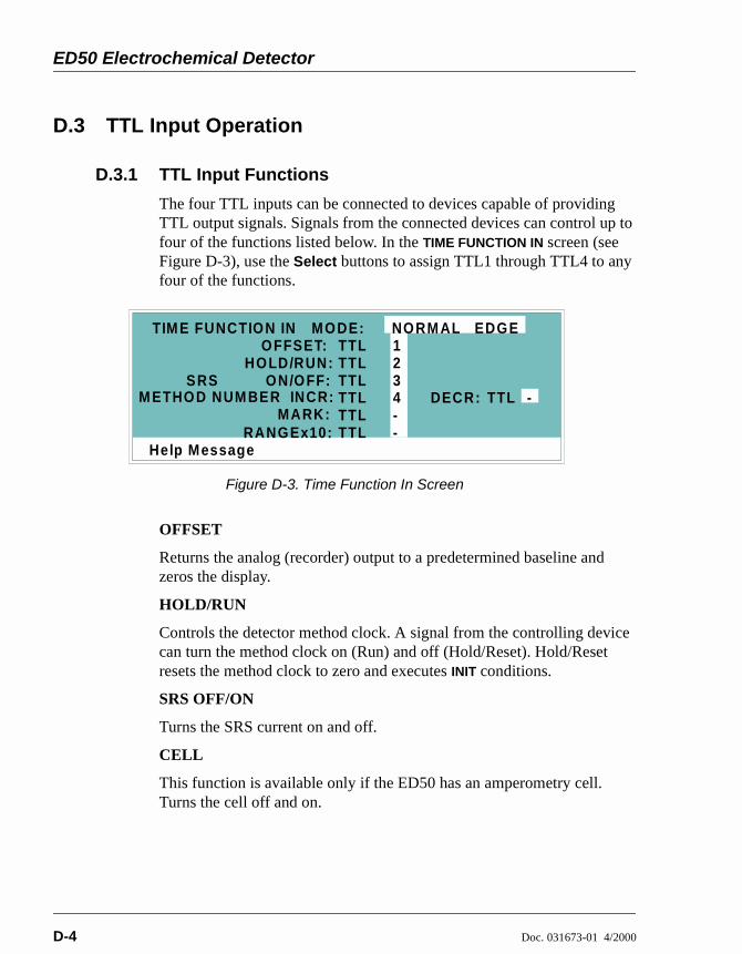
ED50 Electrochemical Detector
D-4 Doc. 031673-01 4/2000
D.3 TTL Input Operation
D.3.1 TTL Input Functions
The four TTL inputs can be connected to devices capable of providing TTL output signals. Signals from the connected devices can control up to four of the functions listed below. In the TIME FUNCTION IN screen (see Figure D-3), use the Select buttons to assign TTL1 through TTL4 to any four of the functions.
OFFSET
Returns the analog (recorder) output to a predetermined baseline and zeros the display.
HOLD/RUN
Controls the detector method clock. A signal from the controlling device can turn the method clock on (Run) and off (Hold/Reset). Hold/Reset resets the method clock to zero and executes INIT conditions.
SRS OFF/ON
Turns the SRS current on and off.
CELL
This function is available only if the ED50 has an amperometry cell. Turns the cell off and on.
Figure D-3. Time Function In Screen
Help Message
HOLD/RUN:ON/OFF:
1234
TIM E FUNCTION INOFFSET:
MARK:RANGEx10:
MODE: NORM AL EDGE
--
TTLTTLTTLTTLTTLTTL
TTLSRS
M ETHOD NUM BER INCR: DECR: -
D • TTL and Relay Control
Doc. 031673-01 4/2000 D-5
METHOD NUMBER INCRement
Increases the method number by one. Each additional signal increases the method number by one more.
When the method clock is zero (or INIT), increasing the method number executes the INIT conditions of the new method. When the method clock is greater than zero, increasing the method number begins running the new method at the current elapsed method clock time. This has the same result as selecting a new method number when the detector is in Local mode.
METHOD NUMBER DECRement
Decreases the method number by one. The operation is as described under TTL input 3 above, except that the method number decreases.
MARK
Sends a 10% positive event mark to the analog (recorder) output.
RANGE x10
Sets the analog output scale factor between 0.01 and 3000 µS.
D.3.2 TTL Input Signal Modes
The ED50 TTL inputs respond to four types of signals to accommodate different types of device output signals. The default signal mode, normal edge, is compatible with the output signals provided by Dionex modules. If the device connected to the ED50 outputs a different signal type, select the appropriate signal mode from the TIME FUNCTION IN screen (see Figure D-3).
The four input signal modes are:
Normal Edge: In normal edge operation, the negative (falling) edge of a signal turns on the function and the positive (rising) edge turns off the function (see Figure D-4).
Inverted Edge: The inverted edge mode works identically to the normal edge mode except that the positive and negative edges are reversed in function.
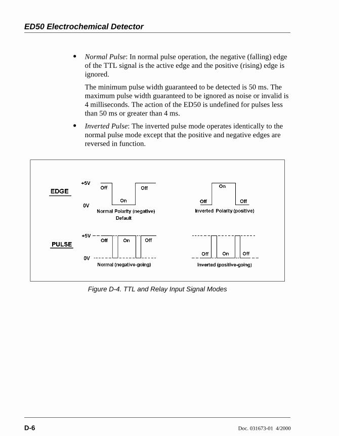
ED50 Electrochemical Detector
D-6 Doc. 031673-01 4/2000
Normal Pulse: In normal pulse operation, the negative (falling) edge of the TTL signal is the active edge and the positive (rising) edge is ignored.
The minimum pulse width guaranteed to be detected is 50 ms. The maximum pulse width guaranteed to be ignored as noise or invalid is 4 milliseconds. The action of the ED50 is undefined for pulses less than 50 ms or greater than 4 ms.
Inverted Pulse: The inverted pulse mode operates identically to the normal pulse mode except that the positive and negative edges are reversed in function.
Figure D-4. TTL and Relay Input Signal Modes

Doc. 031673-01 4/2000 E-1
E • Signal Processor Functions
Table E-1 lists the functions of the Signal Processor (SP) card.
Table E-1. SP Card Functions
Function Cond. DC Amp. Int. Amp. Volt.
Temperature compensation digital-to-analog converter
X
Cell chopper, driver X
Offset digital-to-analog scaling switch X
Conductivity signal receiver X
Second-stage amplifier and gain switch X
Synchronous rectifier X
5 mS noise filter X X X
DC amplifier 100 mS filter X X
Bipolar cell drive analog-to-digital filter X X X
Amperometry cell drive smoothing filter X X X
pH slope and offset corrector X X X
Cell receiver/driver X X X
Fine and coarse integrators X
Signal selection (MUX) X X X X
16-bit analog-to-digital converter X X X X
Digital interface X X X X

ED50 Electrochemical Detector
E-2 Doc. 031673-01 4/2000
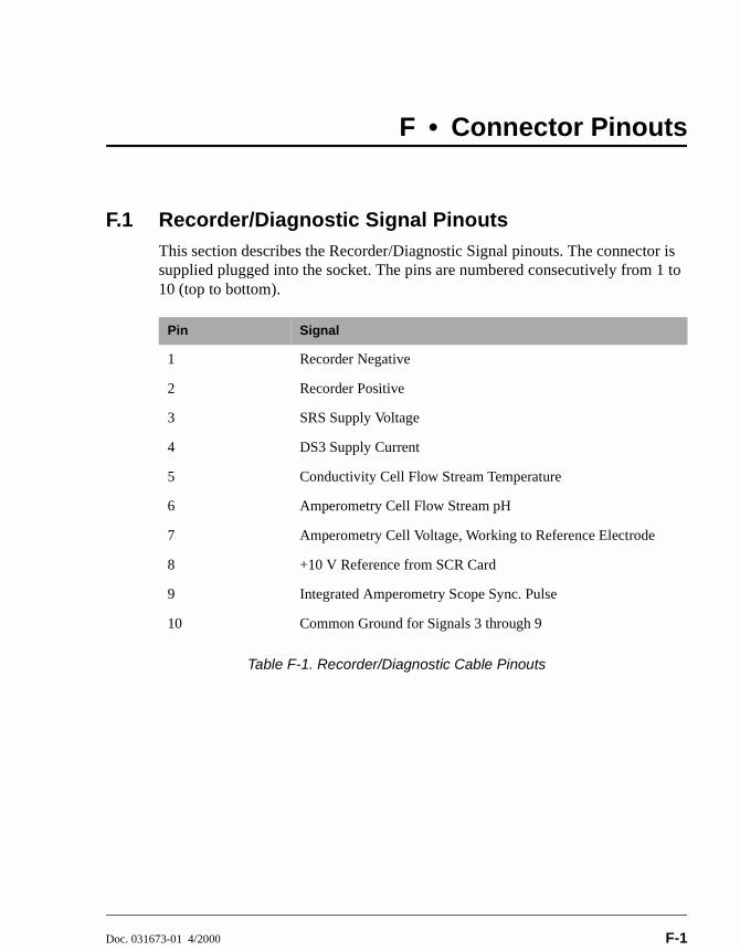
Doc. 031673-01 4/2000 F-1
F • Connector Pinouts
F.1 Recorder/Diagnostic Signal PinoutsThis section describes the Recorder/Diagnostic Signal pinouts. The connector is supplied plugged into the socket. The pins are numbered consecutively from 1 to 10 (top to bottom).
Table F-1. Recorder/Diagnostic Cable Pinouts
Pin Signal
1 Recorder Negative
2 Recorder Positive
3 SRS Supply Voltage
4 DS3 Supply Current
5 Conductivity Cell Flow Stream Temperature
6 Amperometry Cell Flow Stream pH
7 Amperometry Cell Voltage, Working to Reference Electrode
8 +10 V Reference from SCR Card
9 Integrated Amperometry Scope Sync. Pulse
10 Common Ground for Signals 3 through 9
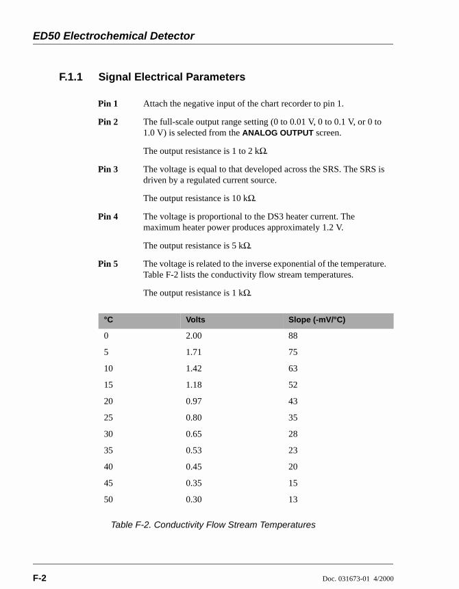
ED50 Electrochemical Detector
F-2 Doc. 031673-01 4/2000
F.1.1 Signal Electrical Parameters
Table F-2. Conductivity Flow Stream Temperatures
Pin 1 Attach the negative input of the chart recorder to pin 1.
Pin 2 The full-scale output range setting (0 to 0.01 V, 0 to 0.1 V, or 0 to 1.0 V) is selected from the ANALOG OUTPUT screen.
The output resistance is 1 to 2 kΩ.
Pin 3 The voltage is equal to that developed across the SRS. The SRS is driven by a regulated current source.
The output resistance is 10 kΩ.
Pin 4 The voltage is proportional to the DS3 heater current. The maximum heater power produces approximately 1.2 V.
The output resistance is 5 kΩ.
Pin 5 The voltage is related to the inverse exponential of the temperature. Table F-2 lists the conductivity flow stream temperatures.
The output resistance is 1 kΩ.
°C Volts Slope (-mV/°C)
0 2.00 88
5 1.71 75
10 1.42 63
15 1.18 52
20 0.97 43
25 0.80 35
30 0.65 28
35 0.53 23
40 0.45 20
45 0.35 15
50 0.30 13

F • Connector Pinouts
Doc. 031673-01 4/2000 F-3
Table F-3. Amperometry Cell Flow Stream Temperatures
Pin 6 The voltage is proportional to the pH, after calibration, as indicated in Table F-3.
The output resistance is 900 Ω.
pH Volts
0 -0.7
1 -0.6
2 -0.5
3 -0.4
4 -0.3
5 -0.2
6 -0.1
7 0.0
8 0.1
9 0.2
10 0.3
11 0.4
12 0.5
13 0.6
14 0.7

ED50 Electrochemical Detector
F-4 Doc. 031673-01 4/2000
Pin 7 The voltage is equal to the applied amperometry cell voltage.
The output resistance is 790 Ω. (The polarity is reversed.)
Pin 8 The signal is 10.00 ± 0.01 V.
The output resistance is 0 Ω.
The maximum load current capability is 10 mA. This output may be divided with a resistor network to provide an offset to a monitoring device. Shorting or overloading this output will disrupt operation of the SCR module.
Pin 9 0 to 5 V logic pulse of 1 mS duration at the start of each integrated amperometry waveform cycle (time zero on the WAVEFORM screen).
The output resistance is approximately 100 Ω.
The maximum current is approximately 10 mA.
Pin 10 A signal ground (0 volts) for monitoring only. Avoid connecting this pin to any grounds or sources of AC or DC current. This ground may be used in common for any of the signals on pins 3 through 9.

F • Connector Pinouts
Doc. 031673-01 4/2000 F-5
F.2 TTL/Relay PinoutsThe TTL and Relay connectors are on the DX-LAN/Relay card. The TTL and Relay connectors all have the same pinout configuration; be careful to use the correct connector.
Table F-4. TTL/Relay Connector Pinouts
Connector Number Pin Number Description
Relay 1 1 and 2 Solid State Relay Contacts Out
Relay 2 1 and 2 Solid State Relay Contacts Out
Relay 3 1 TTL Out (1 kΩ pull up to +5, 100 mA sink)
2 Ground
Relay 4 1 TTL Out (1 kΩ pull up to +5, 100 mA sink)
2 Ground
Relay 5 1 Input TTL 1
2 Ground
Relay 6 1 Input TTL 2
2 Ground
Relay 7 1 Input TTL 3
2 Ground
Relay 8 1 Input TTL 4
2 Ground

ED50 Electrochemical Detector
F-6 Doc. 031673-01 4/2000
F.3 DS3 Connector Pinouts—SCRThe DS3 Detection Stabilizer connects to the SCR card. The connector is a double-row, 1.6 cm (0.63 in) latching displacement connector.
Table F-5. DS3 Connector Pinouts
Pin Number Description
1 DS3 Ground (body)
2 +24 V
3 Base Drive
4 Emitter
5 Emitter
6 Thermistor Ground
7 Thermistor
8 Leak +5 V
9 Leak
10 Leak Ground
11 Disconnect
12 Disconnect Ground (24-gauge)

F • Connector Pinouts
Doc. 031673-01 4/2000 F-7
F.4 SRS Connector Pinouts—SCRThe SRS (Self-Regenerating Suppressor) connects to the SCR card. The connector is a double-row, 0.84 cm (0.33 in) latching displacement connector.
Table F-6. SRS Connector Pinouts
Pin Number Description
1 Ground
2 Thermistor
3 SRS Positive
4 SRS Negative
5 Disconnect Sense
6 Disconnect (Ground)
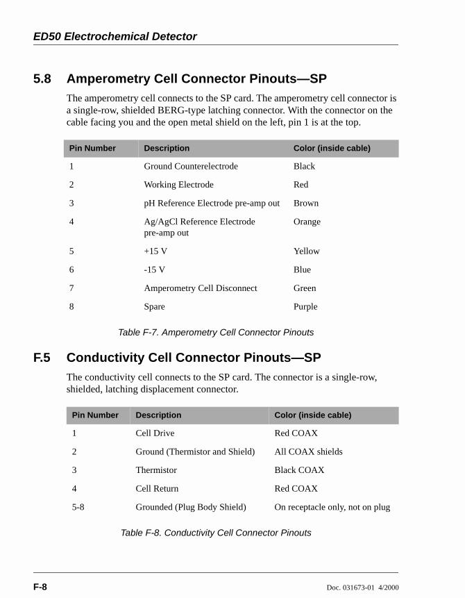
ED50 Electrochemical Detector
F-8 Doc. 031673-01 4/2000
5.8 Amperometry Cell Connector Pinouts—SPThe amperometry cell connects to the SP card. The amperometry cell connector is a single-row, shielded BERG-type latching connector. With the connector on the cable facing you and the open metal shield on the left, pin 1 is at the top.
Table F-7. Amperometry Cell Connector Pinouts
F.5 Conductivity Cell Connector Pinouts—SPThe conductivity cell connects to the SP card. The connector is a single-row, shielded, latching displacement connector.
Table F-8. Conductivity Cell Connector Pinouts
Pin Number Description Color (inside cable)
1 Ground Counterelectrode Black
2 Working Electrode Red
3 pH Reference Electrode pre-amp out Brown
4 Ag/AgCl Reference Electrode pre-amp out
Orange
5 +15 V Yellow
6 -15 V Blue
7 Amperometry Cell Disconnect Green
8 Spare Purple
Pin Number Description Color (inside cable)
1 Cell Drive Red COAX
2 Ground (Thermistor and Shield) All COAX shields
3 Thermistor Black COAX
4 Cell Return Red COAX
5-8 Grounded (Plug Body Shield) On receptacle only, not on plug

Doc. 031673-01 4/2000 G-1
G • Reordering Information
Part Number Item Quantity044130 DS3 Detection Stabilizer 1044132 Shielded Conductivity Cell 1
044108 Amperometry Cell, Gold W.E. 1
044109 Amperometry Cell, Platinum W.E. 1044110 Amperometry Cell, Silver W.E. 1044111 Amperometry Cell, Glassy Carbon W.E. 1045972 Cell Gasket 1045937 Wing Screw 1046617 Amperometry Cell Insulation Plate 1045796 Cell Mounting Screws 1045973 Cell Mounting Washers 1048749 Amperometry Cell Bracket 1
046333 pH Reference Electrode 1045967 pH Reference Electrode Stop Ring 1048410 pH Reference Electrode O-ring 1045968 pH Reference Electrode Compression Nut 1045868 pH Reference Electrode Cable 1
049161 Cable (for connecting Cypress Systems cell electrodes to the ED50 pre-amp board)
1
036313 Polishing Kit 1036319 Coarse Polishing Compound 1036318 Fine Polishing Compound 1049721 Pink Eraser 1036321 Polishing Pads 1
043276 Dionex Ferrule Fittings 1043275 10-32 Fitting Bolts 1042690 0.25-mm (0.010-in) ID Tubing (for cell outlet
backpressure)1

ED50 Electrochemical Detector
G-2 Doc. 031673-01 4/2000
042627 Union (for connecting backpressure tubing to waste line)
1
045460 SRS Gas Separator Waste Tube 1045877 Backpressure Coil for 4 mm SRS 1046346 SRS-to-ED50/ED50 Control Cable 1
042690 0.25-mm (0.010-in) ID Tubing (for DS3 or cell inlet connection)
1
043598 Twisted Black and Red Wires (for recorder/diagnostic and TTL/Relay connections)
1
921019 Green TTL Connector Plugs 1
954745 3.15 Amp Fuse (Fast-Blow IEC127, type 1) 2
960748 IEC Jumper Power Cord 1
Part Number Item Quantity

Doc. 031673-01 4/2000 Index-1
Index
Numerics10BASE-T cable installation, B-510BASE-T DX-LAN interface installation, B-4–B-6
AAbsorbance detection, 1-1AD20 Absorbance Detector, 2-15Ag/AgCl half-cell, 2-15Air bubbles, B-11Amperometry
Plumbing schematic, B-18Amperometry cell
Connections, 2-8Description, 2-14Installation, B-18Maintenance, 3-18Noise test, C-32On/off control, C-8, C-14, C-19Specifications, A-3Time in use, C-27
Analog outputConnections, 2-8Filter, C-23Scale factor, D-5Setup, C-23
Analog output rangeFull-scale output, A-1Selection of, C-3, C-6
Analog test points, C-28Arrow buttons, 2-4AutoSuppression, B-10
BBackpressure limits, 5-2
Backpressure line, 5-2Backpressure requirements, B-11Band broadening, 2-15Baseline
Noisy or drifting, 4-3Oscillations, 2-11, 3-10–3-11
Beep, front panel buttons, C-22Bessel filter, C-23BIOS, 2-10
Revision number, 3-3, C-26BNC DX-LAN interface installation, B-7–B-9BNC tee connector installation, B-8Button descriptions, 2-4–2-5
CCable routing, 2-6Cables
10BASE-T DX-LAN, B-4–B-5Coaxial DX-LAN, B-7–B-8, C-29
Calibrating the cell, 5-4, C-37Calibrating the pH reference electrode, C-38Cards, 2-9
See also Names of cardsCascading hubs, B-6Cell
See Amperometry cellSee Conductivity cell
Circuitry, A/D, C-36Clock
See Method clockCoaxial DX-LAN cable installation, B-8Components, 2-12Conductivity cell, 2-11
See Also DS3 Detection Stabilizer See Also Shielded conductivity cellAir bubble removal, 5-2Backpressure limits, 5-2

Doc. 031673-01 4/2000 Index-2
Index
Backpressure line, 5-2Benefits, 2-11Calibration, 2-11, C-37Calibration constant, 5-4Calibration procedure, 5-4Connections, 2-8Description, 2-11Noise test, C-32Specifications, A-2
Conductivity detection, 1-2Temperature variations, 2-11
Conductivity mode, C-2–C-5Analog output range, C-3Method parameters, C-5Start-up procedure, 3-1Temperature compensation, 3-10–3-11
ConnectorsTTL/Relay control, D-1
Contacting Dionex, 4-1, 5-1Control panel, 2-1–2-2Counterelectrode, 2-14CPU card, 2-10Cursor buttons, 2-4Cursor movement, 2-4Cyclic Voltammetry mode, 3-13, 3-16Cypress Systems, Inc., 3-13
DDAC testing, C-32DC Amperometry, 1-2DC Amperometry mode, C-13–C-16
Detector sensitivity, C-14Method parameters, C-16Start-up procedure, 3-2
Degassing, B-11Delete
Front panel button, 2-3
DeletingField entries, 2-3Method steps, 2-3, 3-9Methods, 3-9
DescriptionTTL input control, D-4
Detection modes, 1-2Selection, C-1
Detector interface card, 2-10Installation procedure, B-4–B-5, B-7–B-8
Detector outputHigh, 4-2Low, 4-2None, 4-1
Detector specifications, A-2Diagnostic Menu, C-1, C-25Diagnostic screens
Accessing, 2-5Diagnostic tests, C-32Diagnostics, 4-12
Accessing, C-25Dionex
Contacting, 4-1Direct control mode, 3-5Display (LCD), 2-1
Backlight, 2-1Backlight adjustment, C-22Time in use, C-27
DS3 Detection Stabilizer, 2-11–2-12, 3-1Benefits, 2-12Connections, 2-8Disassembling, 4-7Installation, B-10, B-13–B-15Leak sensor, 2-12Liquid leaks, 4-7Operating modes, B-10Over/under temperature, C-28Replacing the cell, 5-2

Doc. 031673-01 4/2000 Index-3
Index
Specifications, A-3Start-up, 3-1Temperature compensation, 3-10Temperature reading inaccurate, 4-10Temperature selection, C-4, C-28
DX-LAN10BASE-T cable installation, B-5Coaxial cable installation, B-8–B-9Coaxial cable specifications, C-29
DX-LAN 10BASE-T interfaceInstallation, B-4–B-6
DX-LAN BNC interfaceInstallation, B-7–B-9
DX-LAN card, 2-10See Also Detector interface card
DX-LAN network, 2-6Card, 2-10Error messages, C-29Identification number, 3-3, C-26Problem with communication, 4-12Status screen, C-29
EED50 Electrochemical Detector
Detection modes, 1-2Diagnostics, C-25Dimensions, A-1Electrical connections, 2-7Electrical specifications, A-1Environmental specifications, A-1Function, 1-1Lifting Requirements, B-2Manual conventions, 1-4Replacement parts, 5-1Shutdown procedure, 3-19Time in use, C-27Weight, A-1
Editing Methods, 3-8Electrochemical detection
Molecules detected by, 1-1Electromagnetic interference (EMI), 2-13Electronics, 2-7
Repair procedures, 5-1Testing, C-32
Electronics cards, 2-9See also Names of cards
Electronics chassisConnections, B-7TTL/Relay connections, D-2
Electrostatic discharge (ESD), 2-7Eluents
Conductivity suppression, 2-11Errors
See TroubleshootingEvent marker, 2-3, D-5External regenerant mode, B-10
FFields
Normal video, 2-1Reverse video, 2-1
FilterAnalog output, C-23
Fittings, ferrule, 5-2Front panel, 2-1Front panel buttons
Beeping sound, C-22Description, 2-3–2-5, D-4Testing, C-31
Full-scale output, A-2Fuses, A-1
Rating, 2-6Replacing, 5-9

Doc. 031673-01 4/2000 Index-4
Index
GGas separator waste tube, B-11, G-2Gold electrodes, 5-5GP50 Gradient Pump
SRS control, B-22
HHalf-cells, 2-15Hold/Run
Front panel button, 2-4Hub, 10BASE-T, B-4–B-7, B-9Humidity, operating, A-1
IINIT (initial conditions), 2-4Insert
Front panel button, 2-3Inserting Method steps, 2-3Installation
Detector interface card, B-4–B-5, B-7–B-8DS3 Detection Stabilizer, B-10Shielded conductivity cell, B-10TTL/Relay, D-2TTL/Relay connections, D-2
Installation site, A-1, B-1Integrated Amperometry mode, 1-2, C-7–C-12
Detector sensitivity, C-8Integration periods, C-12Method parameters, C-10Start-up procedure, 3-2Waveforms, 3-12
Integration periodStop/start times, C-12
Inverted edge, D-5Inverted pulse, D-6
KKeypad, 2-1–2-2
Description, 2-3–2-5, D-4–D-5Testing, C-31
LLC10 Chromatography Organizer, 5-4
DS3 installation, B-16LC20 Chromatography Enclosure, 5-4
DS3 installation, B-16LC30 Chromatography Oven, 3-1, 4-3, 5-4
DS3 installation, B-16DS3 temperature range, 3-10
LCD backlightSee also Display (LCD)Time in use, C-27
Leak sensor, C-34Calibration, C-35Status, C-35
LeakingAround cell cables, 4-9DS3, 4-7Reference electrode, 4-5
Leaks, liquid, 5-2Lifting the detector, B-2Local mode
Commands allowed, 2-17Selecting
Locked Remote mode, 2-17
MMain screen, 3-3Maintenance procedures, 3-18Mark
Front panel button, 2-3
Doc. 031673-01 4/2000 Index-5
Index
Selecting in a Method, C-6, C-11, C-17Memory card, 2-9Menu screens
Accessing, 2-5Overview, C-1Selecting options, 2-5, C-2
Method clockControlling with TTL input, D-4Elapsed time, 3-5Starting, 2-4Stopping, 2-4
Method control mode, 3-5Changing parameters, 3-6
Method steps, 2-18Adding, 3-9Blank field, 2-3, 3-7Chronological order, 3-9Creating, 3-7Deleting, 2-3, 3-9Initial conditions, 3-7Maximum number, 3-7Restoring the previous value, 2-3Time 0.0, 3-7Time field, 3-7Viewing additional steps, 3-7–3-8
Methods, 3-5Adding a step, 3-9Changing, 3-8Conductivity screen parameters, C-5Creating, 3-7DC Amperometry parameters, C-16Deleting, 3-9Deleting a step, 3-9Editing, 3-8Integrated Amperometry parameters, C-10Number in memory, 2-18Running a different method, 3-6Running a method, 3-5
Saving, 3-8Saving changes, 3-9Step maximum, 3-7
Mobile phasespH, 2-15, C-9, C-15, C-20
Modes of operationSee Local modeSee Remote mode
Module setup, C-22Moduleware, 2-10, 4-12
Revision number, 3-3, C-26
NNetwork
See DX-LAN networkNonsuppressed mode, B-10
Backpressure requirements, B-12Normal edge, D-5Normal pulse, D-6
OOffset, 3-2
Front panel button, 2-3Selecting in a Method, C-6, C-11, C-17
Offset level, C-23Operating configuration
TTL, D-4Operational screens, 2-5, C-1Optimizing temperature compensation, 3-10O-ring replacement, 5-8
PParts replacement, 5-1
See Also Service procedures

Doc. 031673-01 4/2000 Index-6
Index
PeaksTailing, 4-4
pHMobile phase, C-15
pH half-cell, 2-15pH reading
Always 7.0, 4-4Cannot be set to 7.0, 4-4nonexistent, 4-5
pH reference electrodeSee Reference Electrode
PolarityDC Amperometry mode, C-14Integrated Amperometry mode, C-12Selecting the output voltage polarity, C-23
Polishing compounds, 5-6Polishing working electrodes, 5-5–5-6Potential, 4-6
applied, 3-16DC Amperometry mode, C-14Integrated Amperometry mode, C-12
Potentiostat, 2-14Power connection, B-2Power cord
Requirements for, 2-6Power requirements, A-1Power supply, 2-6
Status, 2-10Power supply card, 2-9Power switch, 2-1
Actuator, 2-1Power-up, 3-3Printed circuit boards
See CardsProblems
See TroubleshootingPulsed Amperometry, 1-2
RRange
DC Amperometry, C-14Integrated amperometry, C-8Selecting the analog output scale, D-5
Rear panelBNC tee connector installation, B-8DX-LAN 10BASE-T cable installation,
B-5DX-LAN coaxial cable installation, B-8
Rear panel description, 2-6Recorders
Analog output setting, C-23Connections, 3-15Installation, B-21
Recycle mode, B-10Redox reactions, 2-15Reference electrode, 2-14–2-15
Calibration, C-38Discolored, 4-5Leaking, 4-5Replacing the O-ring, 5-8Selection, C-9, C-15, C-20Shutdown procedure, 3-19
Refractive index detection, 1-1Relay card, 2-10Relay control
Connections, 2-8Direct control of, C-4, C-9
Remote mode, 2-17Locked Remote, 2-17Selecting
Repair proceduresSee Service procedures
Reproducibility, 2-12Resetting the Method clock, 2-4Reverse peaks, C-23Rise time, C-23

Doc. 031673-01 4/2000 Index-7
Index
RunningMethods, 3-6, C-10Waveforms, 3-17, C-12
SSafety messages, 1-5Saving
Methods, 3-8–3-9SCR card, 2-9Screens
Diagnostic, C-1Operational, C-1
Select buttons, 2-4Self-Regenerating Suppressor
Backpressure requirements, B-11See SRS
SensitivityConductivity mode, C-3DC Amperometry mode, C-14Integrated Amperometry mode, C-8Voltammetry mode, C-19
Service proceduresConductivity cell calibration, 5-4Electronic components, 5-1Fuse replacement, 5-9Polishing the working electrode, 5-5Reference electrode O-ring replacement,
5-8Removing air from the conductivity cell,
5-2Shielded conductivity cell, 2-13
Installation, B-10Temperature compensation, 3-11
Shift in reference, 4-6Shift in reference potential, 4-6Shutdown procedure, 3-19Signal modes for TTL input, D-5
Signal processor cardSee SP card
Signal statistics, C-36Site requirements, B-1SP card, 2-9, E-1SRS
ConnectionsCurrent setting, C-3, C-5Power control, B-22Power supply specifications, A-3Start-up, 3-2Temperature setting, C-28Time in use, C-27Voltage range setting, C-28
StartingMethods, 2-4
Start-up procedure, 3-1Conductivity mode, 3-1DC Amperometry mode, 3-2Integrated Amperometry mode, 3-2
StoppingMethods, 2-4
Strip chart recorderSee Recorders
Supply Control/Relay card, 2-9Symbols on labels, 1-6Systems
Chromatography modules, B-10
TTemperature
Minimizing the effect of variations, 2-11–2-12, 3-11
Reading is inaccurate, 4-10Temperature compensation, 2-11
Optimizing, 3-10Temperature compensation factor, 3-10–3-11

Doc. 031673-01 4/2000 Index-8
Index
Selection, C-4–C-5Temperature, operating, A-1Testing electronics, C-32Thermistor, C-33Time
On the Method clock, 3-5See Also Method clock
Time Function In screen, D-5Timed Method steps, 3-7Triangle wave, 3-16Troubleshooting, 4-1
See Also DiagnosticsCell constant reading inaccurate, 4-11Diagnostic tests, 4-12DS3 is leaking, 4-7DS3 temperature reading inaccurate, 4-10DX-LAN communication, 4-12High detector output, 4-2Low detector output, 4-2No detector response, 4-1Noisy baseline, 4-3pH readout always at 7.0, 4-4pH readout cannot be set to 7.0, 4-4pH readout nonexistent, 4-5Reference electrode is discolored, 4-5Reference electrode leaks, 4-5Reference potential shifts, 4-6Tailing peaks, 4-4
TTL connections, 2-8TTL control
Direct control of, C-4, C-9SRS automatic power control, B-22
TTL/Relay control, D-1Connectors, D-1Input operation, D-4Input signal modes, D-5Installation, D-2Output operation, D-2
TUV, 1-6
VVideo, normal, 2-1Video, reverse, 2-1Voltage, full-scale, C-23Voltammetry mode, 3-13, C-18–C-21
Measuring the cell current, 3-15Non-Dionex cells, 3-13Running a waveform, 3-17Waveform programming, 3-16Waveforms, 3-12
WWarranty, voiding, 5-1Waveform
Running, C-8Waveforms, 3-2, 3-12
Developing for integrated amperometry, 3-13
Programming, 3-16Running, 3-17Selecting a SAVE TO number, C-12Selecting a waveform to edit, C-12Selecting a waveform to run, C-10, C-12
Working electrode, glassy carbonBaseline noise, 3-3Start-up procedure, 3-3
Working electrodesMaintenance, 3-18Materials, 2-14Part numbers, 2-14Polishing, 5-5–5-6, B-19

Doc. 031673-01 4/2000 Index-9
Index
ZZero position, C-23

Doc. 031673-01 4/2000 Index-10
Index