Ecoterre Earth Brick Recommended Fixings Table 5 94721 0 5 40 9,5 30 - 3 - 4 100 UX 5 R 94722 7 5 40...
15
Examples of Suitable Applications *SWL recommended safe working load in tension Dry Wall / stud batons Skirting boards Light shelving Brackets / hooks Boilers Heavy shelving Radiators Door / window frames Bathroom fittings Kitchen fittings Recommended fischer products *SWL (Kg) Load Application Light UX universal plug 18 Medium FUR universal plug 18 FBS concrete screw 37 Heavy FIS V 360 S resin 89 Ecoterre Earth Brick Recommended Fixings Table SUITABLE APPLICATIONS HSS DRILL SET ▪ A straight shank, industrial quality twist drill. Gives good results in most metals, woods and plastics. A tough durable drill bit. OVERVIEW Ideal for drilling in: ▪ Bronze ▪ Hard brass ▪ Steel ▪ Stainless steel Type Art.-No. contents x 1 each of the following sizes: package type qty. per pack 19 Piece HSS Drill Set 14499 1.0, 1.5, 2.0, 2.5, 3.0, 3.5, 4.0, 4.5, 5.0, 5.5, 6.0, 6.5, 7.0, 7.5, 8.0, 8.5, 9.0, 9.5, 10.0 metal case 1
Transcript of Ecoterre Earth Brick Recommended Fixings Table 5 94721 0 5 40 9,5 30 - 3 - 4 100 UX 5 R 94722 7 5 40...

Examples of Suitable Applications
*SWL recommended safe working load in tension
Dry
Wal
l / s
tud
bato
ns
Ski
rting
boa
rds
Ligh
t she
lvin
g
Bra
cket
s / h
ooks
Boi
lers
Hea
vy s
helv
ing
Rad
iato
rs
Doo
r / w
indo
w fr
ames
Bat
hroo
m fi
tting
s
Kitc
hen
fi ttin
gs
Recommended fi scher products
*SWL(Kg)
Load
App
licat
ion
Ligh
t
UX universal plug18
Med
ium FUR universal plug
18
FBS concrete screw37
Hea
vy
FIS V 360 S resin 89
UX universal plug
FBS concrete screw
FIS V 360 S resin
Ecoterre Earth BrickRecommended Fixings Table
SUITABLE APPLICATIONS
HSS DRILL SET
▪ A straight shank, industrial quality twist drill. Gives good results in most metals, woods and plastics. A tough durable drill bit.
OVERVIEW
Ideal for drilling in:▪ Bronze▪ Hard brass▪ Steel▪ Stainless steel
Type Art.-No. contents x 1 each of the following sizes: package type qty. per pack
19 Piece HSS Drill Set 14499 1.0, 1.5, 2.0, 2.5, 3.0, 3.5, 4.0, 4.5, 5.0, 5.5, 6.0, 6.5, 7.0, 7.5, 8.0, 8.5, 9.0, 9.5, 10.0metal case
1
▪ Nylon universal fi xing▪ Expansion in solid building materials, reliable knot formation
in all cavities.▪ Use UX 6 long versions with fi scher spacing screws for
maximum load-bearing capacity in perforated materials, double-skinned plasterboard and for bridging non-load-bearing layers.
Advantages/Benefi ts▪ The unique design enables use in almost all building
materials.▪ Diagonal connection ridges for optimum screw guidance.▪ New saw-tooth anti-rotation lock prevents the fi xing rotating
in the drill hole.▪ Low turning and high tightening torque - the fi rst universal
fi xing that really “holds“.
▪ Can be used with wood and chipboard screws between 4 and 12 mm.
▪ Integral drive-in lock enables optimal push-through installation. If pre-assembled with screw.
▪ The collar of the UX R prevents it slipping into the drill hole.
DESCRIPTION
Pre-positioned installation
Push-through installation
Type of installation▪ Pre-positioned and push-through installation.
Installation information▪ With push-through installation, use the largest possible screw diameter.▪ Drill only in a rotary motion (switch
off hammer) in perforated and hollow brick and aerated concrete, and use a
metal bit for plasterboard.▪ If using hook screws and eye screws in cavity bricks, it is essential that they
have a collar, so that the screw can be tightened enough to collapse the plug fully.▪ The required screw length is given by the fi xing length +
thickness of the item being attached + 1 x screw diameter.
INSTALLATION
OVERVIEW
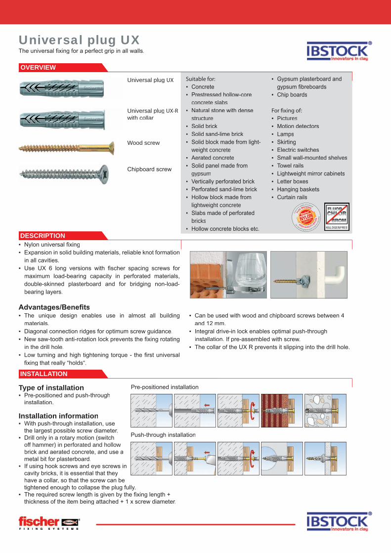
Universal plug UX
Universal plug UX-Rwith collar
Suitable for:▪ Concrete▪ Prestressed hollow-core
concrete slabs▪ Natural stone with dense
structure▪ Solid brick▪ Solid sand-lime brick▪ Solid block made from light-
weight concrete▪ Aerated concrete▪ Solid panel made from
gypsum▪ Vertically perforated brick▪ Perforated sand-lime brick▪ Hollow block made from
lightweight concrete▪ Slabs made of perforated
bricks▪ Hollow concrete blocks etc.
▪ Gypsum plasterboard and gypsum fi breboards
▪ Chip boards
For � xing of:▪ Pictures▪ Motion detectors▪ Lamps▪ Skirting▪ Electric switches▪ Small wall-mounted shelves▪ Towel rails▪ Lightweight mirror cabinets▪ Letter boxes▪ Hanging baskets▪ Curtain rails
Wood screw
Chipboard screw
Universal plug UXThe universal fi xing for a perfect grip in all walls.

1 x screw-ø
UX - without collar UX R - with collar UX RS- with chipboard screw
Type Art.-No. ID drill-Ø min. drill hole depth min. panel thickness anchor length usable length chipboard screw qty. per box
do
t dp
l da
ds x l
s
[mm] [mm] [mm] [mm] [mm] [Ø mm] pcs.
UX 5 94721 0 5 40 9,5 30 - 3 - 4 100
UX 5 R 94722 7 5 40 9,5 30 - 3 - 4 100
UX 6 x 35 62754 9 6 45 9,5 35 - 4 - 5 100
UX 6 x 35 R 62756 3 6 45 9,5 35 - 4 - 5 100
UX 6 x 50 72094 3 6 60 9,5 50 - 4 - 5 100
UX 6 x 50 R 72095 0 6 60 9,5 50 - 4 - 5 100
UX 8 x 50 77869 2 8 60 9,5 50 - 4,5 - 6 100
UX 8 x 50 R 77870 8 8 60 9,5 50 - 4,5 - 6 100
UX 10 x 60 77871 5 10 75 12,5 60 - 6 - 8 50
UX 10 x 60 R 77872 2 10 75 12,5 60 - 6 - 8 50
UX 12 x 70 62758 7 12 85 - 70 - 8 - 10 25
UX 14 x 75 62757 0 14 95 - 75 - 10 - 12 20
UX 6 x 35R S/20 94758 6 6 60 9,5 35 20 4.5 x 60 25
UX 6 x 50R S/20 94759 3 6 75 9,5 50 20 4,5 x 75 25
UX 8 x 50R S/15 94762 3 8 70 9,5 50 15 5 x 70 25
UX 8 x 50R S/25 94760 9 8 80 9,5 50 25 5 x 80 25
UX 10 x 60 S/20 94761 6 10 85 12,5 60 20 6 x 85 10
TECHNICAL DATA
LOADS
Recom. loads Nrec [kN] and mean ultimate loads Nu [kN]. These values apply to the use of wood screws with the given screw diameter. When use chipboard screws these values should be reduced by 30%.
Fixing type UX 6 x 35 UX 6 x 50 (R) UX 8 x 50 UX 10 x 60 UX 12 x 70 UX 14 x 75Wood screw diameter [mm] 5 6 5 8 10 12Substrate N
recN
uN
recN
uN
recN
uN
recN
uN
recN
uN
recN
u
Concrete ≧ C12/C55 0.4 2.4 0.6 2.5 0.6 2.5 1.0 5.8 1.5 8.8 1.8 13.2Solid brick ≧ Mz12 (DIN 105) 0.2 2.0 0.3 2.1 0.3 2.1 0.5 3.7 0.7 8.0 0.8 8.0Vertical perforated brick ≧ Hlz12 (ρ ≧ 1.0 kg/dm3, DIN 105) 0.2 0.9 0.2 0.9 0.2 1.0 0.2 1.4 0.3 2.1 0.4 3.2Sand-lime perforated brick ≧ KSL12 (DIN 106) 0.4 2.6 0.4 2.8 0.5 3.2 0.6 4.4 0.8 5.0 0.8 5.0Aerated concrete ≧ PB2 0.05 0.4 0.1 0.5 0.15 0.7 0.2 1.1 0.2 1.6 0.2 1.7Aerated concrete ≧ PB4 0.2 1.0 0.2 1.3 0.3 1.7 0.4 2.7 0.6 3.7 0.7 3.9Plasterboard 12,5 mm 0.1 0.5 0.1 0.5 0.1 0.6 0.1 0.6 – – – –Plasterboard 2 x 12.5 mm 0.15 0.7 0.15 0.8 0.15 0.8 0.15 1.1 – – – –Gypsum fibre board (Fermacell) 0.2 1.5 0.2 1.5 0.2 1.7 0.25 1.9 – – – –

OVERVIEW
FUR-T - fi scher safety screw withcountersunk head
FUR 8-SS andFUR 10-SS -fi scher safety screw with hexagon-head
FUR 10 andFUR 14 F US -fi scher safety screw with hexagon-head
INSTALLATION
Universal frame fi xing FURThe high-performance facade fi xing - locks in each building material.
▪ Universal frame fi xing.▪ Anchorage in solid mate-
rials by means of friction locking.
▪ The asymmetrical close set teeth expand and formlock in hollow materi-als.
▪ Fixing sets with A4 stain-less steel safety screws can for applications in damp conditions.
Advantages/benefi ts▪ Universal for all building
materials. ▪ All the fi xings with pre-
installed screw.
▪ Patented asymmetrical teeth guarantee high load-bearing capacity in solid and perforated brick.
▪ Integral hammer-in stop prevents the fi xing from spreading prematurely during installation.
▪ The FUR-FUS version does not require additio-nal washers and prevents contact corrosion.
▪ Large range for wood and metal constructions (internal and exterior) for many applications.
DESCRIPTION
Approved for:▪ Concrete▪ Solid brick▪ Solid sand-lime brick▪ Vertically perforated brick▪ Perforated sand-lime
block▪ Hollow block made from
lightweight concrete▪ No-fi nes lightweight con-
crete▪ Multilayer composite
concrete wall
Also suitable for:▪ Natural stone with dense
structure▪ Solid block made from
lightweight concrete▪ Solid panel made from
gypsum▪ Aerated concrete
For fi xing of:▪ Facade and roof substruc-
tures made of wood and metal
▪ Gates▪ Door frames▪ Fire protection doors▪ Windows▪ Kitchen cabinets▪ Wardrobes▪ Squared timbers▪ Facings
Type of installation▪ Push-through installation
Installation tips▪ We advise countersunk-head screws for fi xing wooden structures, and fi xings with a fl at edge
and hexagon-head bolts for metal structures. ▪ The hexagon-head with integral washer also has an integral
� -socket.▪ With vertically perforated bricks only use rotary drilling (no
impact drilling).

FUR-T - fischer safety screw with countersunk head
FUR-T A4 - with stainless steel A4 fischer safety screw
Type Art.-No. ID approvals drill-Ø min. drill-hole depth for through
fi xings
eff ect. anchorage depth
anchor length max. usable length
fi scher safety screw
drive qty. per box
DIBt do
td
hef
l t fi x
ds x l
s
[mm] [mm] [mm] [mm] [mm] [mm] pcs.
FUR 8 x 80 T 70110 2 ▯ 8 90 70 80 10 6 x 85 T30 50
FUR 8 x 100 T 70111 9 ▯ 8 110 70 100 30 6 x 10⁵ T30 50
FUR 8 x 120 T 70112 6 ▯ 8 130 70 120 50 6 x 125 T30 50
FUR 10 x 80 T 88756 1 ▯ 10 90 70 80 10 7 x 85 T40 50
FUR 10 x 100 T 88757 8 ▯ 10 110 70 100 30 7 x 10⁵ T40 50
FUR 10 x 115 T 88760 8 ▯ 10 125 70 115 45 7 x 120 T40 50
FUR 10 x 135 T 88758 5 ▯ 10 145 70 135 65 7 x 140 T40 50
FUR 10 x 160 T 88759 2 ▯ 10 170 70 160 90 7 x 165 T40 50
FUR 10 x 185 T 88761 5 ▯ 10 195 70 185 115 7 x 190 T40 50
FUR 10 x 200 T 88764 6 ▯ 10 210 70 200 130 7 x 205 T40 50
FUR 10 x 230 T 88762 2 ▯ 10 240 70 230 160 7 x 235 T40 50
FUR 14 x 100 T 48711 2 ▯ 14 115 70 100 30 10 x 110 T50 50
FUR 14 x 140 T 48712 9 ▯ 14 155 70 140 70 10 x 150 T50 50
FUR 14 x 165 T 48713 6 ▯ 14 180 70 165 95 10 x 175 T50 50
FUR 14 x 180 T 48714 3 ▯ 14 195 70 180 110 10 x 190 T50 50
FUR 14 x 210 T 48844 7 ▯ 14 225 70 210 140 10 x 220 T50 50
FUR 14 x 240 T 48715 0 ▯ 14 255 70 240 170 10 x 250 T50 50
FUR 14 x 270 T 48716 7 ▯ 14 285 70 270 200 10 x 280 T50 50
FUR 14 x 300 T 90759 7 ▯ 14 315 70 300 230 10 x 310 T50 20
FUR 14 x 330 T 90760 3 ▯ 14 345 70 330 260 10 x 340 T50 20
FUR 14 x 360 T 90761 0 ▯ 14 375 70 360 290 10 x 370 T50 20
FUR 8 x 80 T A4 70120 1 ▯ 8 90 70 80 10 6 x 85 T30 50
FUR 8 x 100 T A4 70121 8 ▯ 8 110 70 100 30 6 x 10⁵ T30 50
FUR 8 x 120 T A4 70122 5 ▯ 8 130 70 120 50 6 x 125 T30 50
FUR 10 x 80 T A4 88784 4 ▯ 10 90 70 80 10 7 x 85 T40 50
FUR 10 x 100 T A4 88785 1 ▯ 10 110 70 100 30 7 x 10⁵ T40 50
FUR 10 x 115 T A4 88791 2 ▯ 10 125 70 115 45 7 x 120 T40 50
FUR 10 x 135 T A4 88786 8 ▯ 10 145 70 135 65 7 x 140 T40 50
FUR 10 x 160 T A4 88787 5 ▯ 10 170 70 160 90 7 x 165 T40 50
FUR 10 x 185 T A4 88788 2 ▯ 10 195 70 185 115 7 x 190 T40 50
FUR 10 x 200 T A4 88789 9 ▯ 10 210 70 200 130 7 x 205 T40 50
FUR 10 x 230 T A4 88790 5 ▯ 10 240 70 230 160 7 x 235 T40 50
FUR 14 x 140 T A4 48719 8 ▯ 14 155 70 140 70 10 x 150 T50 50
FUR 14 x 165 T A4 48720 4 ▯ 14 180 70 165 95 10 x 175 T50 50
FUR 14 x 180 T A4 48721 1 ▯ 14 195 70 180 110 10 x 190 T50 50
FUR 14 x 210 T A4 48845 4 ▯ 14 225 70 210 140 10 x 220 T50 50
For matching cover caps ADT, see page 158.
TECHNICAL DATA
Universal frame fi xing FUR
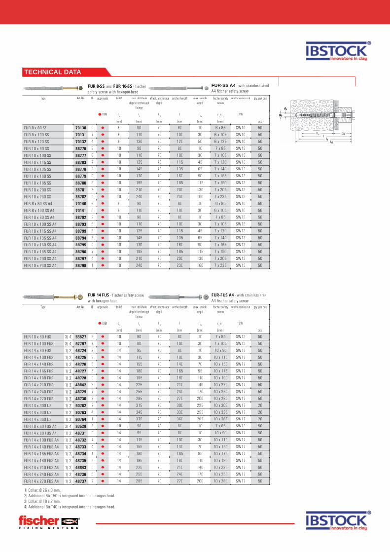
FUR 8-SS and FUR 10-SS - fischer safety screw with hexagon-head
FUR-SS A4 - with stainless steel A4 fischer safety screw
Type Art.-No. ID approvals drill-Ø min. drill-hole depth for through
fi xings
eff ect. anchorage depth
anchor length max. usable length
fi scher safety screw
width across nut qty. per box
DIBt do
td
hef
l t fi x
ds x l
sSW
[mm] [mm] [mm] [mm] [mm] [mm] pcs.
FUR 8 x 80 SS 70130 0 ▯ 8 90 70 80 10 6 x 85 SW10 50
FUR 8 x 100 SS 70131 7 ▯ 8 110 70 100 30 6 x 10⁵ SW10 50
FUR 8 x 120 SS 70132 4 ▯ 8 130 70 120 50 6 x 125 SW10 50
FUR 10 x 80 SS 88776 9 ▯ 10 90 70 80 10 7 x 85 SW13 50
FUR 10 x 100 SS 88777 6 ▯ 10 110 70 100 30 7 x 10⁵ SW13 50
FUR 10 x 115 SS 88783 7 ▯ 10 125 70 115 45 7 x 120 SW13 50
FUR 10 x 135 SS 88778 3 ▯ 10 145 70 135 65 7 x 140 SW13 50
FUR 10 x 160 SS 88779 0 ▯ 10 170 70 160 90 7 x 165 SW13 50
FUR 10 x 185 SS 88780 6 ▯ 10 195 70 185 115 7 x 190 SW13 50
FUR 10 x 200 SS 88781 3 ▯ 10 210 70 200 130 7 x 205 SW13 50
FUR 10 x 230 SS 88782 0 ▯ 10 240 70 230 160 7 x 235 SW13 50
FUR 8 x 80 SS A4 70140 9 ▯ 8 90 70 80 10 6 x 85 SW10 50
FUR 8 x 100 SS A4 70141 6 ▯ 8 110 70 100 30 6 x 10⁵ SW10 50
FUR 10 x 80 SS A4 88792 9 ▯ 10 90 70 80 10 7 x 85 SW13 50
FUR 10 x 100 SS A4 88793 6 ▯ 10 110 70 100 30 7 x 10⁵ SW13 50
FUR 10 x 115 SS A4 88799 8 ▯ 10 125 70 115 45 7 x 120 SW13 50
FUR 10 x 135 SS A4 88794 3 ▯ 10 145 70 135 65 7 x 140 SW13 50
FUR 10 x 160 SS A4 88795 0 ▯ 10 170 70 160 90 7 x 165 SW13 50
FUR 10 x 185 SS A4 88796 7 ▯ 10 195 70 185 115 7 x 190 SW13 50
FUR 10 x 200 SS A4 88797 4 ▯ 10 210 70 200 130 7 x 205 SW13 50
FUR 10 x 230 SS A4 88798 1 ▯ 10 240 70 230 160 7 x 235 SW13 50
TECHNICAL DATA
FUR 14 FUS - fischer safety screw with hexagon-head
FUR-FUS A4 - with stainless steel A4 fischer safety screw
Type Art.-No. ID approvals drill-Ø min. drill-hole depth for through
fi xings
eff ect. anchorage depth
anchor length max. usable length
fi scher safety screw
width across nut qty. per box
DIBt do
td
hef
l t fi x
ds x l
sSW
[mm] [mm] [mm] [mm] [mm] [mm] pcs.
FUR 10 x 80 FUS 3) 4) 93527 9 ▯ 10 90 70 80 10 7 x 85 SW13 50
FUR 10 x 100 FUS 3) 4) 97797 2 ▯ 10 80 70 100 30 7 x 10⁵ SW13 50
FUR 14 x 80 FUS 1) 2) 48724 2 ▯ 14 95 70 80 10 10 x 90 SW17 50
FUR 14 x 100 FUS 1) 2) 48725 9 ▯ 14 115 70 100 30 10 x 110 SW17 50
FUR 14 x 140 FUS 1) 2) 48726 6 ▯ 14 155 70 140 70 10 x 150 SW17 50
FUR 14 x 165 FUS 1) 2) 48727 3 ▯ 14 180 70 165 95 10 x 175 SW17 50
FUR 14 x 180 FUS 1) 2) 48728 0 ▯ 14 195 70 180 110 10 x 190 SW17 50
FUR 14 x 210 FUS 1) 2) 48842 3 ▯ 14 225 70 210 140 10 x 220 SW17 50
FUR 14 x 240 FUS 1) 2) 48729 7 ▯ 14 255 70 240 170 10 x 250 SW17 50
FUR 14 x 270 FUS 1) 2) 48730 3 ▯ 14 285 70 270 200 10 x 280 SW17 50
FUR 14 x 300 US 1) 2) 90762 7 ▯ 14 315 70 300 225 10 x 305 SW17 20
FUR 14 x 330 US 1) 2) 90763 4 ▯ 14 345 70 330 255 10 x 335 SW17 20
FUR 14 x 360 US 1) 2) 90764 1 ▯ 14 375 70 360 285 10 x 365 SW17 20
FUR 10 x 80 FUS A4 3) 4) 93528 6 ▯ 10 90 70 80 10 7 x 85 SW13 50
FUR 14 x 80 FUS A4 1) 2) 48731 0 ▯ 14 95 70 80 10 10 x 90 SW17 50
FUR 14 x 100 FUS A4 1) 2) 48732 7 ▯ 14 115 70 100 30 10 x 110 SW17 50
FUR 14 x 140 FUS A4 1) 2) 48733 4 ▯ 14 155 70 140 70 10 x 150 SW17 50
FUR 14 x 165 FUS A4 1) 2) 48734 1 ▯ 14 180 70 165 95 10 x 175 SW17 50
FUR 14 x 180 FUS A4 1) 2) 48735 8 ▯ 14 195 70 180 110 10 x 190 SW17 50
FUR 14 x 210 FUS A4 1) 2) 48843 0 ▯ 14 225 70 210 140 10 x 220 SW17 50
FUR 14 x 240 FUS A4 1) 2) 48736 5 ▯ 14 255 70 240 170 10 x 250 SW17 50
FUR 14 x 270 FUS A4 1) 2) 48737 2 ▯ 14 285 70 270 200 10 x 280 SW17 50
1) Collar: Ø 26 x 3 mm. 2) Additional Bit T50 is integrated into the hexagon head. 3) Collar: Ø 18 x 2 mm. 4) Additional Bit T40 is integrated into the hexagon head. 4) Additional Bit T40 is integrated into the hexagon head.

LOADS
Recommended loads Nrec1) [kN] and mean ultimate loads Nu [kN] with large axial spacing and edge distance
Fixing type FUR 8 FUR 10 FUR 14Substrate N
rec1) N
uN
rec1) N
uN
rec1) N
u
Concrete ≧ C12/15 [kN] 1.2 8.1 2.1 10.0 3.1 21.9Solid brick ≧ Mz12 (DIN 105) [kN] 0.7 5.0 1.4 10.0 1.8 12.5Solid sand lime brick ≧ KS12 (DIN 106) [kN] 1.1 7.8 1.6 12.8 2.8 19.7Vertical perforated brick ≧ Hlz12 (ρ≧1.0 kg/dm³, DIN 105) [kN] 0.13 0.9 0.37 2.6 0.5 2)
Perforated sand lime brick ≧ KSL12 (DIN 106) [kN] 0.63 4.4 0.48 3.3 0.6 2)
Hollow block ≧ Hbl2 (lightweight concrete, DIN 18151) 3) [kN] 0.17 1.2 0.46 3.2 0.31 2.2Solid block ≧ V2 (lightweight concrete, DIN 18152) [kN] 0.56 3.9 0.71 5.0 0.5 2)
1) Safety factor for the material (γM
) and for the load (γL) included.
2) Due to large range of scatter of test results not suitable, the failure of the substrate varies so greatly that no reproducible values can be given.3) The expanding part of the fixing must anchor in the wall of the brick.

Concrete screw FBSThe simple and time-saving threaded concrete screw for the cracked or tension zone.
DESCRIPTION
▪ Self-tapping concrete screw for push-through and prior insertion installation
▪ When the concrete screw is screwed into the hole, the thread taps into the concrete and creates a positive fi t anchorage.
▪ A4 stainless steel version for outdoor use or in damp conditions.
Advantages/benefi ts▪ Setting and installation in one working operation saves
time.▪ Completely removable anchor, therefore particularly suitable
for temporary fi xings (e.g. shuttering supports).▪ Virtually expansion-free operation allows cost-effi cient fi xing
with small axial spaces and edge distances.▪ Serrations on the thread makes the screws easy to screw
in.▪ Re-usability of the screws reduces costs.▪ Fixing with different head designs for different areas of
OVERVIEW
Approved for:▪ Cracked and non-cracked
concrete C20/25 to C50/60▪ Lightweight ceilings
and suspended ceilings according to DIN 18168
▪ Statically comparable fi x-ings
Also suitable for:▪ Concrete C12/15▪ Natural stone with dense
structure▪ Solid brick,▪ Solid sand-lime brick
For fi xing of:▪ Handrails▪ Consoles▪ Ladders▪ Cable trays▪ Machines▪ Gates▪ Facades▪ Window elements▪ Battens
▪ Metal profi les▪ Wire hangers▪ Chains▪ Cables▪ Punched tapes▪ Ventilation pipes▪ Substructures made of
wood and metal▪ Ceilings
Concrete screwFBS-P, panhead
Concrete screwFBS-SK,countersunk head
Concrete screw FBS-US, hexagon head with integrated washer
Concrete screwFBS-S,hexagon head
Concrete screw FBS-M8, outside diameter M8
Concrete screwFBS-M8/M10,internal thread M8/M10
FBS M12 Concrete screw with thread and hexagon drive, stainless steel

Concrete screw FBS-P panhead,zinc-plated steel
Concrete screw FBS-SK counter-sunk head, zinc-plated steel
Type Art.-No. ID approval drill-Ø drill-hole diameter in object
screwdiameter
drill hole depth anchorage depth max. usable length
actuation qty. per box
DIBt do
df
ds
h0
hef
t fi x
[mm] [Ø mm] [mm] [mm] [mm] [mm] pcs.
FBS 5/5 P 66774 3 ▯ 5 7 6,5 65 55 5 T30 100
FBS 6/5 SK 66935 8 ▯ 6 8 7,6 65 55 5 T30 100
FBS 6/5 P 66939 6 ▯ 6 8 7,6 65 55 5 T30 100
FBS 6/25 P 66948 8 ▯ 6 8 7,6 65 55 25 T30 100
Concrete screw FBS-M8,outside diameter M8,zinc-plated steel
Concrete screw FBS-M8/M10, internal thread M8/M10,zinc-plated steel
Type Art.-No. ID approval drill-Ø drill-hole diameter in object
screwdiameter
min. drill-hole depth for through
fi xings
anchorage depth thread width across nut qty. per box
DIBt do
df
ds
td
hef
M SW
[mm] [Ø mm] [mm] [mm] [mm] pcs.
FBS 6 M8 66949 5 ▯ 6 8 7,6 60 55 M 8 SW10 100
FBS 6 M8/M10I 66950 1 ▯ 6 8 7,6 60 55 M 8 SW13 100
Concrete screw FBS-US, hexagon head with integrated washe
Concrete screw FBS-S,hexagon head
Type Art.-No. ID approval drill-Ø drill-hole diameter in object
screwdiameter
drill hole depth anchorage depth max. usable length
actuation qty. per box
DIBt do
df
ds
h0
hef
t fi x
[mm] [Ø mm] [mm] [mm] [mm] [mm] pcs.
FBS 8/5 US 66956 3 ▯ 8 12 10,5 90 75 5 T40/SW13 100
FBS 8/25 US 66957 0 ▯ 8 12 10,5 110 75 25 T40/SW13 100
FBS 8/15 S 66958 7 ▯ 8 12 10,5 100 75 15 SW 16 100
FBS 10/5 S 67062 0 ▯ 10 14 12,5 100 85 5 SW 18 50
FBS 10/15 S 67063 7 ▯ 10 14 12,5 110 85 15 SW 18 50
FBS 10/25 S 67168 9 ▯ 10 14 12,5 120 85 25 SW 18 50
FBS 10/10 S A4 67169 6 ▯ 10 14 12,5 105 85 10 SW 17 50
FBS 10/20 S A4 98336 2 ▯ 10 14 12,5 115 85 20 SW 17 50
TECHNICAL DATA
INSTALLATION
Type of installation▪ Pre-positioned installation▪ Push-through installation
Installation tips▪ We recommend use of an impact wrench with tangen-
tial impact (see the table for power output).
Performance details of impact wrenchConcrete screw recommended installation torque
FBS 5 100 [Nm]FBS 6FBS 8 200 [Nm]FBS 10 300 [Nm]
Use nuts (black) which fit percussion power screwdrivers!

LOADS
Design resistant and recommended loads for single anchors of fi scher Concrete screw FBS with large axial spacing and edge distance
Non-cracked concrete Cracked concreteAnchor size FBS 8 FBS 10 FBS 5* FBS 6* FBS 8* FBS 10Effective anchorage depth h
efef[mm] 50 60 55 55 50 60
Drill hole depth h0 0
≧ [mm] 85 95 60 60 85 95Screw in depth h
nomnom ≧ [mm] 75 85 55 55 75 85
Drill hole diameter d00
[mm] 8 10 5 6 8 10
Design resistant loads NRd and VRd [kN]
Tensile 0° NRd
[kN]gvz 7.2 9.0 0.4 1.1 3.4 5.4A4 – 9.0 – – – 5.4
Shear 90° VRd
[kN]gvz 10.3 16.9 – – 10.4 16.9A4 – 19.0 – – – 17.6
Recommended loads Nrec and Vrec [kN]
Tensile 0° Nrec
[kN]gvz 5.1 6.4 0.3 0.8 2.4 3.9A4 – 6.4 – – – 3.9
Shear 90° Vrec
[kN]gvz 7.4 12.1 – – 7.4 12.1A4 – 13.6 – – – 12.6
Recommended bending moment Mrec [Nm]
Mrec
[Nm]gvz 19.0 40.0 – 8.0 19.0 40.0A4 – 36.8 – – – 36.8
Component dimensions, minimum axial spacings and edge distancesMin. axial spacing1) s
minmin[mm] 50 60 50 50 50 60
Min. edge distance1) cminmin
[mm] 70 65 100 100 70 65Min. structural component thickness h
minmin[mm] 120 130 110 110 120 130
* For the fixing of lightweight suspended ceiling constructions only.1) For min. axial spacing and min. edge distance the above described loads have to be reduced! (See design software “CC-Compufix”)All load values apply for concrete C20/25 without edge or spacing influence.Design resistant loads: material safety factor γ
M is included. Material safety factor γ
M depends on type of anchor.
Recommended loads: material safety factor γM
and safety factor for load γL = 1.4 are included.
The conditions of application diff er from those given in the German Approval.For further detailed information about approvals please contact your local fi scher representative.
TECHNICAL DATA
FBS M12 Concrete screw with thread and hexagon drive, zinc-plated steel
FBS M12 A4 Concrete screw with thread and hexagon drive, stainless steel
Type Art.-No. ID approval drill-Ø drill-hole diameter in
object
screwdiameter
drill hole depth
anchorage depth
max. usable length
thread width across nut
qty. per box
DIBt do
df
ds
h0
hef
t fi x
M SW
[mm] [Ø mm] [mm] [mm] [mm] [mm] pcs.FBS 10 M12/30 1) 98339 3 ▯ 10 14 12,5 125 85 30 M 12 9 50
FBS 10 M12/53 1) 98340 9 ▯ 10 14 12,5 148 85 53 M 12 9 50
FBS 10 M12/40 A4 1) 98337 9 ▯ 10 14 12,5 135 85 40 M 12 9 50
FBS 10 M12/60 A4 1) 98338 9 ▯ 10 14 12,5 155 85 60 M 12 9 50
1) Including nuts and washer, not pre-assembled.
Concrete screw FBS

Approvals:▪ European Technical
Approval Option 7 in conjunction with Threaded rods FIS A resp. RG M for non-cracked concrete.
▪ German approval (DIBt) in conjunction with injection anchor sleeve FIS H M and injection anchor parts FIS G and FIS E for solid and hollow bricks (solid brick also without anchor sleeve).
▪ German approval (DIBt) for aerated cement in conjunction with cone drill PBB, centering sleeve PBZ and Threaded rod FIS G.
▪ German approval (DIBt) for reinforcement bars.
▪ German approval (DIBt) for Remedial wall tie VBS 8.
▪ German approval (DIBt) for Weather facing reno-vation system FWS.
▪ ICC-Approval for threaded rods and rebars
For fi xing of:▪ Steel constructions▪ Railings▪ Hand-rails▪ Consoles▪ Ladders▪ Machines▪ Cable trays▪ Staircases▪ Gates▪ Facades▪ Window elements▪ High racks▪ Canopies▪ Stand-off installations
OVERVIEW
Injection mortarFIS V 360 S,styrene free
Static mixer FIS S
Injection mortar FIS VThe high-performance hybrid mortar in the shuttle cartridge.
DESCRIPTION
▪ Styrene-free, quick-curing high-performance hybrid mortar (contains vinyl ester resin and cement).
▪ Resin and cement as well as water and hardener are stored in two separate chambers and are not mixed and activated until pushed through the static mixer.
▪ Partially-used cartridges can easily be reused by changing the static mixer.
Advantages/Benefi ts▪ High-performance hybrid mortar for highest loads in almost
all building materials. ▪ Universal fi xing system for a broad range of applications on
building sites. ▪ Expansion-free anchoring allows low axial spacings and
edge distances. ▪ Extensive range of accessories for a wide variety of
applications. ▪ Ergonomic injection guns for quick and easy installation.▪ A variety of approvals cover many applications in nearly all
building material and guarantee maximum safety.▪ First injection system world-wide with approvals for
concrete, reinforcement bars, solid bricks, perforated bricks and aircrete.
Accessories / Recommended loads▪ For fi xing in concrete▪ For fi xing in masonry▪ For fi xing in aerated concrete▪ For reinforcement bars▪ Appropriate injection guns
Injection mortarFIS VS 150C, styrene free
Can be extruded using a standard silicone gun

Injection mortar FIS V 360 S,styrene free
Type Art.-No. ID approvals contents
languages on the lable shelf life qty. per box
DIBt ■ ETA
months pcs.
FIS V 360 S 94405 9 ▯ ■1 cartridge 360 ml +2 static mixers
- 18 6
FIS VS 150C 45303 21 cartridge 154ml + 2 static mixers
- 18 6
FIS S 61223 1 10 static mixer FIS V 360 S - - 10
TECHNICAL DATA
CURING TIME
Gelling and curing time of fi scher FIS V
Cartridge temperature(mortar)
Gelling time Temperature atanchoring base
Curing time
- 5°C — ± 0°C 24 hrs.± 0°C — + 5°C 3 hrs.
+ 5°C — + 10°C 13 min. + 5°C — + 10°C 90 min.+ 10°C — + 20°C 5 min. + 10°C — + 20°C 60 min.+ 20°C — + 30°C 4 min. + 20°C — + 30°C 45 min.+ 30°C — + 40°C 2 min. + 30°C — + 40°C 35 min.
The above times apply from the moment of contact between resin and hardener in the static mixer.For installation, the cartridge temperature must be at least +5°C. For longer installation times, i.e. when interruptions occur in work, the mixer should be replaced.
Resin AccessoriesOVERVIEW
Internally threaded sockets FIS E
Internally threaded sockets FIS M I
Injection anchor sleeve with netFIS H N
Injection anchor sleeve, 1 m length FIS H L
Injection anchor sleeve, plasticFIS H K
Approval:▪ German approval (DIBt) in
conjunction with Injection mortar FIS V, and FIS G FIS E for solid and hollow material
With anchor sleeve suitable for:▪ Vertically perforated bricks▪ Perforated sand-lime brick▪ Hollow blocks▪ Solid brick▪ Solid sand-lime brick▪ Hollow pumice plank▪ Slabs made of perforated
bricks and other perforated blocks
Without anchor sleeve suitable for:▪ Lightweight concrete▪ Solid bick▪ Solid sand-lime bricks▪ Full pumice stone and other
solid building materials▪ Aerated concrete
For fi xing of:▪ Machines▪ Gratings▪ Gates ▪ Hand-rails▪ Consoles▪ Pipelines▪ Sanitary equipment▪ Cable trays▪ Facades▪ Awnings▪ Canopies▪ Wooden constructions
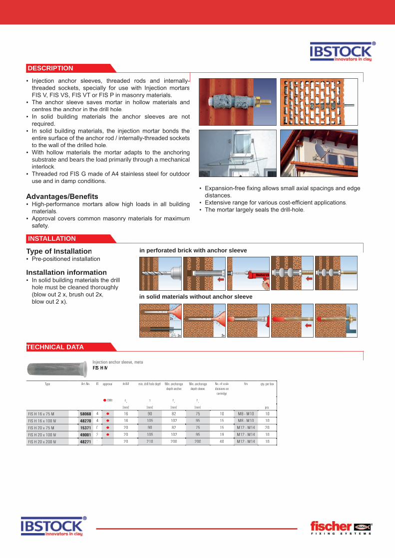
DESCRIPTION
▪ Injection anchor sleeves, threaded rods and internally-threaded sockets, specially for use with Injection mortarsFIS V, FIS VS, FIS VT or FIS P in masonry materials.
▪ The anchor sleeve saves mortar in hollow materials and centres the anchor in the drill hole.
▪ In solid building materials the anchor sleeves are not required.
▪ In solid building materials, the injection mortar bonds the entire surface of the anchor rod / internally-threaded sockets to the wall of the drilled hole.
▪ With hollow materials the mortar adapts to the anchoring substrate and bears the load primarily through a mechanical interlock.
▪ Threaded rod FIS G made of A4 stainless steel for outdoor use and in damp conditions.
Advantages/Benefi ts▪ High-performance mortars allow high loads in all building
materials.▪ Approval covers common masonry materials for maximum
safety.
▪ Expansion-free fi xing allows small axial spacings and edge distances.
▪ Extensive range for various cost-effi cient applications.▪ The mortar largely seals the drill-hole.
Injection anchor sleeve, metalFIS H M
Type Art.-No. ID approval drill-Ø min. drill hole depth Min. anchorage depth anchor
Min. anchorage depth sleeve
No. of scale divisions on
cartridge
fi ts qty. per box
DIBt do
t hv
hv
[mm] [mm] [mm] [mm] pcs.
FIS H 16 x 75 M 58068 4 ▯ 16 90 82 75 10 M8 - M10 10
FIS H 16 x 100 M 48270 4 ▯ 16 105 102 95 15 M8 - M10 10
FIS H 20 x 75 M 15371 0 ▯ 20 90 82 75 15 M12 - M14 20
FIS H 20 x 100 M 49001 3 ▯ 20 105 102 95 19 M12 - M14 10
FIS H 20 x 200 M 48271 1 20 210 200 200 40 M12 - M14 10
TECHNICAL DATA
INSTALLATION
in perforated brick with anchor sleeve
in solid materials without anchor sleeve
Type of Installation▪ Pre-positioned installation
Installation information▪ In solid building materials the drill
hole must be cleaned thoroughly (blow out 2 x, brush out 2x,blow out 2 x).

TECHNICAL DATA
Injection anchor sleeve with net FIS H N
Type Art.-No. ID drill-Ø min. drill hole depth
Min. anchorage depth anchor
Min. anchorage depth sleeve
No. of scale divisions on
cartridge
fi ts qty. per box
do
t hv
hv
[mm] [mm] [mm] [mm] pcs.
FIS H 16 x 85 N 50470 3 16 95 90 85 15 Ø8/M8 20
FIS H 18 x 85 N 50472 7 18 95 90 85 17 Ø10/M10/FIS 18/M8 I 20
FIS H 20 x 85 N 50474 1 20 95 90 85 19 Ø12/M12/FIS 20/M10 I 20
Injection anchor sleeve, plastic FIS H K
Type Art.-No. ID drill-Ø min. drill hole depth
Min. anchorage depth anchor
Min. anchorage depth sleeve
No. of scale divisions on
cartridge
fi ts qty. per box
do
t hv
hv
[mm] [mm] [mm] [mm] pcs.
FIS H 12 x 60 K 50432 1 12 70 60 60 6 Ø4/M4 - Ø8/M8 20
FIS H 12 x 80 K 1) 58045 5 12 90 80 80 9 Ø4/M4 - Ø8/M8 20
FIS H 14 x 70 K 50436 9 14 80 70 70 7 Ø6/M6 - Ø10/M10 10
FIS H 14 x 90 K 1) 58046 2 14 100 90 90 10 Ø6/M6 - Ø10/M10 10
FIS H 16 x 80 K 50433 8 16 90 80 80 11 Ø8/M8 - Ø12/M12 10
FIS H 16 x 100 K 1) 58047 9 16 110 100 100 12 Ø8/M8 - Ø12/M12 10
1) Anchor sleeve with up to 20mm plaster bridging.
Injection anchor sleeve, 1 m length FIS H L
Type Art.-No. ID drill-Ø total length fi ts qty. per box
do
l
[mm] [mm] pcs.
FIS H 12 x 1000 L 50598 4 12 1000 Ø6 / M 6 - Ø8 / M 8 10
FIS H 16 x 1000 L 50599 1 16 1000 Ø10/M10 10
FIS H 22 x 1000 L 45301 8 22 1000 Ø12/M12 - Ø16/M16 6
Injection anchor sleeve, plastic FIS H K
Type Art.-No. ID drill-Ø min. drill hole depth
Min. anchorage depth anchor
Min. anchorage depth sleeve
No. of scale divisions on
cartridge
fi ts qty. per box
do
t hv
hv
[mm] [mm] [mm] [mm] pcs.
FIS H 12 x 50 K 41900 7 12 60 - - 5 - 50
FIS H 12 x 85 K 41901 4 12 95 - - 10 - 50
FIS H 16 x 85 M 41902 1 16 95 - - 12 - 50
FIS H 16 x 130 M 41903 8 16 140 - - 15 - 50
FIS H 20 x 85 M 41904 5 20 95 - - 15 - 50

FIS brush Ø 14/20 mm FIS brush Ø 20/30 mm
Type Art.-No. ID qty. per box
FIS-brush Ø14/20 mm 48980 2 2
FIS-brush Ø20/30 mm 48981 9 2
Internally threaded socketsFIS M I
Internally threaded socketsFIS E
Type Art.-No. ID approval eff ect.anchorage depth
min.bolt penetration
max.bolt penetration
internal thread fi ts qty. per box
▯ DIBt hef
e2
e1
ds
[mm] [mm] [mm] pcs.
FIS 18/M8 I 50480 2 ▯ 85 8 23 M 8 FIS H 18 x 85 N 20
FIS 20/M10I 50481 9 ▯ 85 10 28 M 10 FIS H 20 x 85 N 20
FIS E 11 x 75 M8 58069 1 ▯ 75 8 60 M 8 FIS H 20 x 75 M 20
FIS E 15 x 75 M10 16248 4 ▯ 75 10 60 M 10 FIS H 20 x 75 M 20
FIS E 15 x 75 M12 16249 1 ▯ 75 12 60 M 12 FIS H 20 x 75 M 20
TECHNICAL DATA
Suitable for: Lightweight concrete, solid brick, solid sand-lime brick, solid pumice and other solid materials
Approved for:Solid bricks ≧ Mz 12, solid sand-lime bricks≧ KS 12.
Type Injection threaded rod FIS G M... Internally threaded sockets FIS E...
Screw-inserts FIS E...K
Dimension 8 x 100 8 x 125 8 x 125 10 x 95 10 x 110 10 x 145 12 x 105 12 x 130 12 x 150 11 x 75 M8
15 x 75 M10
15 x 75 M12
5 x 45 12 x 100 6 x 75 1) 8 x 85 1) 10 x 95 1)
Approval
Usable length tfix
[mm] 15 40 20 10 25 40 15 40 40 — — — — — — — —
Drill diameter d0 [mm] 10 10 10 12 12 12 14 14 14 14 18 18 10 18 10 14 14
Drill depth td [mm] 80 80 80 90 90 90 110 110 110 90 90 90 45 100 60 70 80
Suitable brush-∅ [mm] 14 14 14 14 14 14 20 20 20 20 20 20 14 20 14 20 20
Anchoring depth hef [mm] 75 75 95 75 75 95 75 75 95 75 75 75 45 100 60 70 80
No. of scale units 3 3 4 4 4 5 5 5 7 4 4 4 2 7 3 4 5
1) With detachable plaster bridging. Included in German approval.
CORRECT USE WITHOUT ANCHOR SLEEVE