Echo Measurement Utility (EMU) - GL COMMUNICATIONS INC...echo canceller (EC) in the gateway, which...
29
1 818 West Diamond Avenue - Third Floor, Gaithersburg, MD 20878 Phone: (301) 670-4784 Fax: (301) 670-9187 Email: [email protected] Website: https://www.gl.com 1 Echo Measurement Utility (EMU)
Transcript of Echo Measurement Utility (EMU) - GL COMMUNICATIONS INC...echo canceller (EC) in the gateway, which...
1
818 West Diamond Avenue - Third Floor, Gaithersburg, MD 20878 Phone: (301) 670-4784 Fax: (301) 670-9187 Email: [email protected]
Website: https://www.gl.com 1
Echo Measurement Utility (EMU)

2
Basic Concept
• GL’s Echo Measurement Utility (EMU) software is an offline adjunct analysis application (under control of VQuad™) that
compares the source and received files to determine echoes and delay of echoes
• EMU software assess sidetone, line, and acoustic echo and the corresponding delays

3
• Detect Acoustic/Line (Hybrid) echoes and evaluate intermittent echoes
• Echo, Delay, and Voice Quality Analysis of Voice Calls in VoIP, TDM, 2Wire, and Mobile
Networks
• Measures EPD in msec and ERL in dB
• Compares source and received files to detect echo (maximum of four instances)
• Supports Auto Method and Manual Method of operation
• Ability to automate the entire test process using VQuad™ scripting; including sending the
results to the central database for access via GL’s WebViewer™
• EMU uses EMU Client software to automatically detect the incoming degraded voice files
and send the measurements to database after analysis
• Graphically displays source signal, received signal, error signal, and adaptive filter
coefficients
• Calculates adaptive filter coefficients and echo characteristics for the error signal
Features

4
User Interface
• Provides Delay and ERL measurements for all detected echoes, along with an ‘ERL vs Delay’ plot
• Includes signal graphs for source signal, received signal, error signal, and adaptive filter coefficients
EMU GUI

5
Measurement Parameters
• Customizable parameters to control the EMU input and output includes - Filter Coefficients Length, Step Size, Double talk
Detector Threshold, Double talk Detector Hangover Time, Echo power window length, Single talk Threshold, ERL threshold,
Minimum Single talk length, Maximum Single talk length and Sampling rate
EMU GUI
6
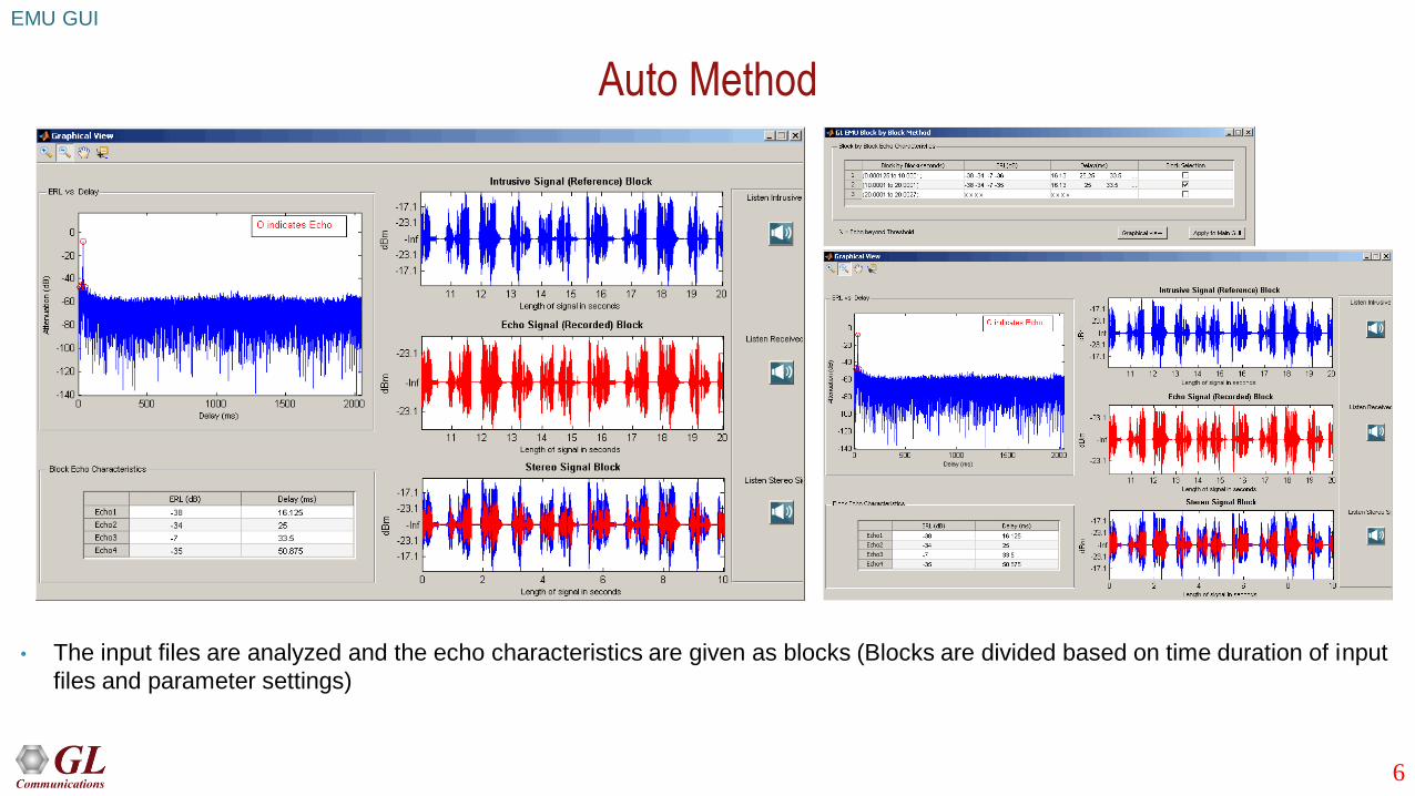
Auto Method
• The input files are analyzed and the echo characteristics are given as blocks (Blocks are divided based on time duration of input
files and parameter settings)
EMU GUI
7
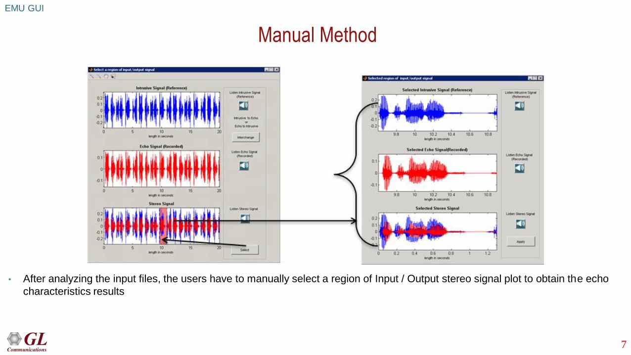
Manual Method
• After analyzing the input files, the users have to manually select a region of Input / Output stereo signal plot to obtain the echo
characteristics results
EMU GUI

8
Detailed Analysis
• Displays received signal (in dBm format), error signal (in seconds), calculates adaptive filter coefficients and provides up to 4
echo characteristics
EMU GUI
9
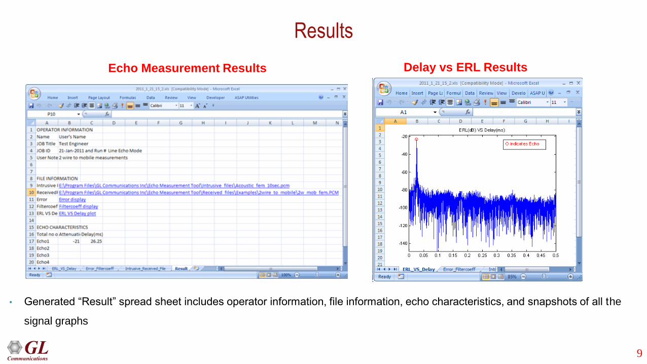
Results
Echo Measurement Results
• Generated “Result” spread sheet includes operator information, file information, echo characteristics, and snapshots of all the
signal graphs
Delay vs ERL Results

10
Testing Scenarios
EMU
• EMU in Line (Hybrid) Echo Mode of Operation
➢ Two wire – Two wire Setup
➢ Two wire – Mobile Setup
➢ Two wire (direct to gateway) to VoIP Phone Setup
➢ Two wire (through T1/E1 Switch) to VoIP phone setup
➢ Two wire (through T1/E1 Switch) to VQuad™ software (Ethernet Interface) Setup
➢ Two wire (direct to gateway) to VQuad™ software (Ethernet Interface) Setup
➢ Mobile phone to Mobile phone Setup
➢ Mobile phone to VoIP phone Setup
➢ VQuad™ (Ethernet Interface) to IP PBX to two-wire Setup
➢ VoIP phone to IP PBX to Two-wire Setup
• EMU in Acoustic Echo Mode of Operation
11
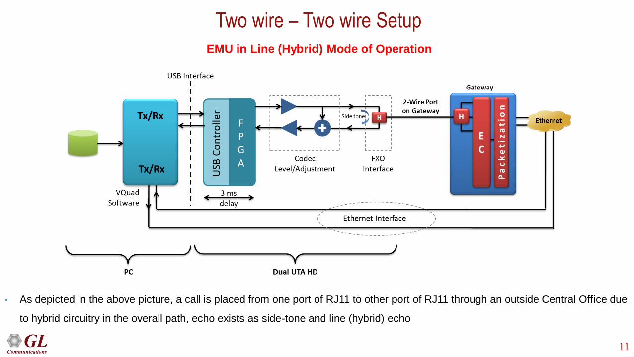
Two wire – Two wire Setup
EMU in Line (Hybrid) Mode of Operation
• As depicted in the above picture, a call is placed from one port of RJ11 to other port of RJ11 through an outside Central Office due
to hybrid circuitry in the overall path, echo exists as side-tone and line (hybrid) echo

12
Two wire – Mobile Setup
• Call is placed from one port of RJ11 to a mobile where the connection path is shown above. Echo cancellers exist in the two-wire
to mobile path between central office to base station
• Intrusive file sent from Port of RJ11 (2-wire) to mobile - The one echo, which can be seen in this setup, is the side-tone as shown
at 2-wire connection
• Intrusive file sent from mobile to Port of RJ11 (2-wire) - There will be no side tone with mobile connection, but there could be line
(hybrid) echo depending on the EC performance / existence

13
Two wire (direct to gateway) -VoIP Phone Setup
• Call is placed from one port of RJ11 to VoIP phone through the gateway and Ethernet network. Based on the configuration of
echo canceller (EC) in the gateway, which can be enabled or disabled, echo exists at the VoIP phone. At the PC / Dual UTA there
will be side-tone
• Intrusive file sent from Port of RJ11 (2-wire) to VoIP phone - The one echo, which can be seen in this setup with Echo Canceller
setting enabled, is the side-tone as shown at 2-wire connection
14
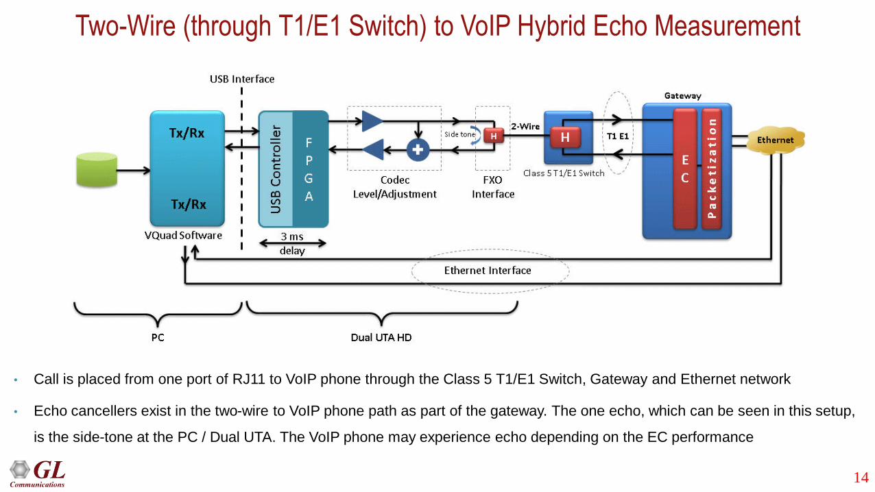
Two-Wire (through T1/E1 Switch) to VoIP Hybrid Echo Measurement
• Call is placed from one port of RJ11 to VoIP phone through the Class 5 T1/E1 Switch, Gateway and Ethernet network
• Echo cancellers exist in the two-wire to VoIP phone path as part of the gateway. The one echo, which can be seen in this setup,
is the side-tone at the PC / Dual UTA. The VoIP phone may experience echo depending on the EC performance

15
Two-Wire (through T1/E1 Switch) to VQuad™ Software (Ethernet Interface) Setup
• Call is placed from one port of RJ11 to Ethernet interface of VQuad™ software through the T1/E1 Switch, Gateway and Ethernet
network. Echo cancellers exist in the two-wire to Ethernet interface of VQuad™ software path between T1/E1 Switch
• The one echo, which can be seen in this setup, is the side-tone. On the VoIP side, there may be echo based on the performance
of the EC
16
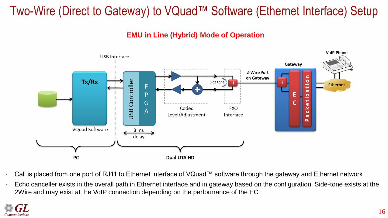
Two-Wire (Direct to Gateway) to VQuad™ Software (Ethernet Interface) Setup
• Call is placed from one port of RJ11 to Ethernet interface of VQuad™ software through the gateway and Ethernet network
• Echo canceller exists in the overall path in Ethernet interface and in gateway based on the configuration. Side-tone exists at the
2Wire and may exist at the VoIP connection depending on the performance of the EC
EMU in Line (Hybrid) Mode of Operation
17
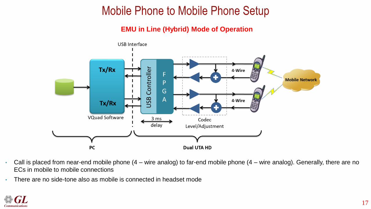
Mobile Phone to Mobile Phone Setup
• Call is placed from near-end mobile phone (4 – wire analog) to far-end mobile phone (4 – wire analog). Generally, there are no
ECs in mobile to mobile connections
• There are no side-tone also as mobile is connected in headset mode
EMU in Line (Hybrid) Mode of Operation

18
Mobile Phone to VoIP Phone Setup
Call is placed from near-end mobile phone (4 – wire analog) to Ethernet interface of the other port via VoIP phone or vice versa.
• Intrusive file sent from Mobile to VoIP phone or VQuad™ (Ethernet Interface) - Echo cancellers exist in the mobile network.
There is no side-tone as mobile is connected in headset mode
• Intrusive file sent from VoIP phone or VQuad™ (Ethernet Interface) to Mobile - Echo cancellers exist in overall path. The one
echo, which can be seen in this setup, is the side-tone at the VoIP phone
19
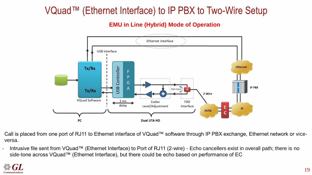
VQuad™ (Ethernet Interface) to IP PBX to Two-Wire Setup
Call is placed from one port of RJ11 to Ethernet interface of VQuad™ software through IP PBX exchange, Ethernet network or vice-
versa.
• Intrusive file sent from VQuad™ (Ethernet Interface) to Port of RJ11 (2-wire) - Echo cancellers exist in overall path; there is no
side-tone across VQuad™ (Ethernet Interface), but there could be echo based on performance of EC
EMU in Line (Hybrid) Mode of Operation

20
VoIP Phone to IP PBX to Two-Wire Setup
• Call is placed from one port of RJ11 to VoIP phone through IP PBX exchange, Ethernet network or vice-versa
• Intrusive file sent from VoIP phone to RJ11 (2-wire) port - Echo cancellers exist in overall path
• The one echo, which can be seen in this setup, is the side-tone as shown across the VoIP phone
EMU in Line (Hybrid) Mode of Operation

21
EMU in Acoustic Echo Mode of Operation
• Call is being generated from RTP ToolBox™ (or VQuad™ VoIP SIP Soft phone) of computer 1 to computer 2. The configuration
at computer 2 is such that the file received at computer 2 is played to the speaker and the audio is sent back to source using the
microphone
• The intrusive and the received files at computer 1 are compared for echo measurement
• The path of acoustic echo is depicted in dotted lines, which is the leak between the speaker and mic of computer 2

22
EMU with GL Tools
The EMU requires only two files to function – the ’sent’ file and simultaneously recorded ‘received’ file. Any tool that
achieves this can be used with EMU. GL offers various emulation and capture tools that are compatible with the
EMU:
• For VoIP: VQuad™ or RTP Toolbox™
• For Mobile Phones: VQuad™ with Dual UTA HD
• For TDM: VQuad™ with USB T1 E1 unit, or tProbe™ T1 E1 unit alone, or USB T1 E1 unit alone, Universal T1
E1 Card alone
• For 2Wire: VQuad™ with Dual UTA
• For 4Wire: VQuad™ with Dual UTA
EMU

23
EMU with VQuad™ and Dual UTA HD
• VQuad™ software along with the Dual UTA HD hardware supports transmitting and receiving files across the following interfaces:
RJ11 2-wire analog, 3.5 mm jack for mobile headset connection, Handset phones and balanced I/O for VoIP soft phones
EMU with VQuad™ software

24
EMU with GL’s Intrusive RTP ToolBox™ Tool
• GL’s RTP Toolbox™ or VQuad™ with VoIP option can be used with EMU to assess line or acoustic echo
EMU with RTP Toolbox™ Tool

25
EMU with GL’s Intrusive T1/E1 Analyzers
• GL’s T1/E1 Analysis application (requires hardware) is used with EMU to detect possible echoes through a T1/E1 channel
• Through T1/E1 WCS scripting or VQuad™ with T1/E1 option it is possible to automate the entire testing process including
sending and receiving files
• The intrusive files and the received files are fed as input to EMU for further analysis
26
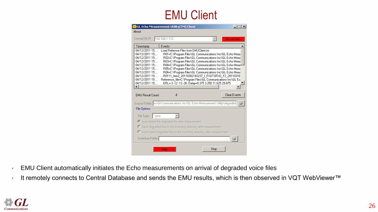
EMU Client
• EMU Client automatically initiates the Echo measurements on arrival of degraded voice files
• It remotely connects to Central Database and sends the EMU results, which is then observed in VQT WebViewer™

27
EMU Results in WebViewer™
28
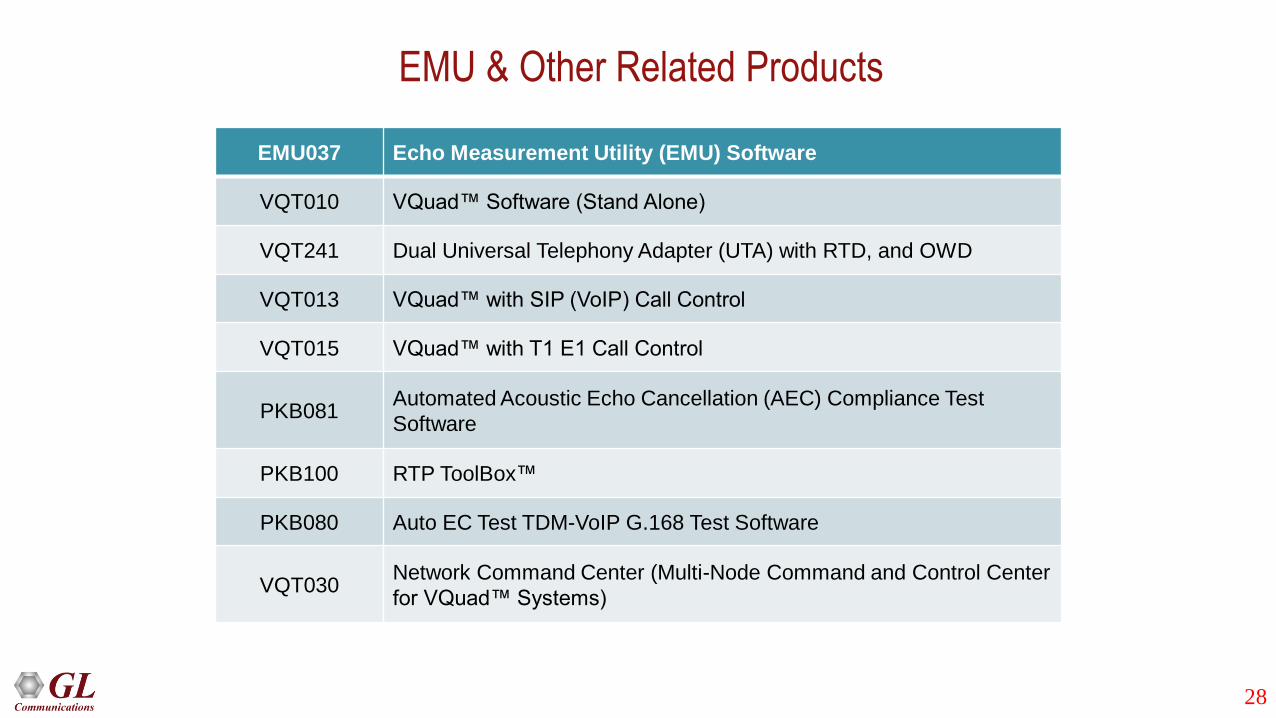
EMU037 Echo Measurement Utility (EMU) Software
VQT010 VQuad™ Software (Stand Alone)
VQT241 Dual Universal Telephony Adapter (UTA) with RTD, and OWD
VQT013 VQuad™ with SIP (VoIP) Call Control
VQT015 VQuad™ with T1 E1 Call Control
PKB081Automated Acoustic Echo Cancellation (AEC) Compliance Test
Software
PKB100 RTP ToolBox™
PKB080 Auto EC Test TDM-VoIP G.168 Test Software
VQT030Network Command Center (Multi-Node Command and Control Center
for VQuad™ Systems)
EMU & Other Related Products

29
Thank You