ECE 6560 Multirate Signal Processing Chapter 8bazuinb/ECE6560/Chap_08.pdfECE 6560 Multirate Signal...
53
ECE 6560 Multirate Signal Processing Chapter 8 Dr. Bradley J. Bazuin Western Michigan University College of Engineering and Applied Sciences Department of Electrical and Computer Engineering 1903 W. Michigan Ave. Kalamazoo MI, 49008-5329
Transcript of ECE 6560 Multirate Signal Processing Chapter 8bazuinb/ECE6560/Chap_08.pdfECE 6560 Multirate Signal...

ECE 6560Multirate Signal Processing
Chapter 8
Dr. Bradley J. BazuinWestern Michigan University
College of Engineering and Applied SciencesDepartment of Electrical and Computer Engineering
1903 W. Michigan Ave.Kalamazoo MI, 49008-5329

ECE 6560 Notes and figures are based on or taken from materials in the course textbook: fredric j. harris, Multirate Signal Processing for Communication Systems, Prentice Hall PTR, 2004. ISBN 0-13-146511-2.
2
Chapter 8: Half-band Filters 8.1 Half-band Low Pass Filters 2028.2 Half-band High Pass Filters 2048.3 Window Design of Half-band Filters 2058.4 Remez Alorithm Design of Half-band Filters 207
8.4.1 Half-band Remez Algorithm Design Trick 2088.5 Hilbert Transform Band-pass Filter 210
8.5.1 Applying the Hilbert Transform Filter 2128.6 Interpolating with Low Pass Half-band Filters 2148.7 Dyadic Pass Half-band Filters 217

ECE 6560 Notes and figures are based on or taken from materials in the course textbook: fredric j. harris, Multirate Signal Processing for Communication Systems, Prentice Hall PTR, 2004. ISBN 0-13-146511-2.
3
Rectangular Low Pass Filter
12
rectf
ffH
tffth 11 2sinc2
tf
tffth
1
11 2
2sin2
tf
tf
fth
222
222sin
21
1
1
11
11
21
222:
ft
tfzeroFirst
zerost
zerost
ECE 6560 Notes and figures are based on or taken from materials in the course textbook: fredric j. harris, Multirate Signal Processing for Communication Systems, Prentice Hall PTR, 2004. ISBN 0-13-146511-2.
4
Half-Band Low Pass Filter
sfffH 2rect
tffth ss
2sinc
2
tf
tffth
s
s
s
142
42sin
42
tf
tffth
s
s
s
2
2sin
2
szerost
zerosts
ft
tfzeroFirst
22
:
1
1
41sffLet
ECE 6560 Notes and figures are based on or taken from materials in the course textbook: fredric j. harris, Multirate Signal Processing for Communication Systems, Prentice Hall PTR, 2004. ISBN 0-13-146511-2.
5
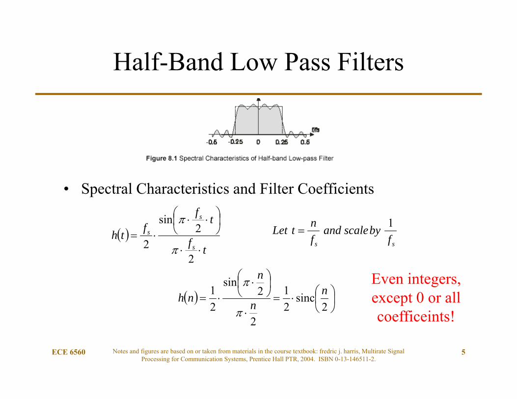
Half-Band Low Pass Filters
• Spectral Characteristics and Filter Coefficients
ss fbyscaleand
fntLet 1
tf
tffth
s
s
s
2
2sin
2
2
sinc21
2
2sin
21 n
n
n
nh
Even integers, except 0 or all coefficeints!

ECE 6560 Notes and figures are based on or taken from materials in the course textbook: fredric j. harris, Multirate Signal Processing for Communication Systems, Prentice Hall PTR, 2004. ISBN 0-13-146511-2.
6
Half-Band Coefficients
• Filter length “2N+1”– But there are N zero coefficients for N even or
N-1 zero coefficients for N odd– Note: always select N as odd
(i.e. if N=2M+1, then 2N+1=>4M+3)
Chap8_1.m - odd
Chap8_1c.m - even
4M+3 and 4M+5 use the same
non-zero coefficients!

ECE 6560 Notes and figures are based on or taken from materials in the course textbook: fredric j. harris, Multirate Signal Processing for Communication Systems, Prentice Hall PTR, 2004. ISBN 0-13-146511-2.
7
Computation Load
• There is one multiply for every unique coefficient– Conventional filter
• 4M-taps 4M Multiplies, 4M-1 Adds– Half-Band filter
• 4M+3 taps 2M+3 Multiplies, 2M+2 Adds– Half-Band filter, if h(0) doesn’t require a multiply,
• 4M+3 taps 2M+2 Multiplies, 2M+2 Adds– Half-Band filter, if h(0) doesn’t require a multiply and symmetric,
• 4M+3 taps M+1 Multiplies, M+M+1 Adds
• Potential savings: approximately ¼ the multiplies and ½ the adds!
Half-Band Length Consideration
• Since the half-band filter is originally defined by the sincfunction, it must be “windowed” to a finite length.– Apply a rectangular filter of length 4M+3 or 4M+5(?!)
• The finite length filter will always appear as a “perfect half-band” convolved by a frequency domain function related to the window used (rect or other).
• Expect ripples in the passband and stopband!– Improved if windowed by other than rect function.
ECE 6560 Notes and figures are based on or taken from materials in the course textbook: fredric j. harris, Multirate Signal Processing for Communication Systems, Prentice Hall PTR, 2004. ISBN 0-13-146511-2.
8
Chap8_1.m
Chap8_1c.m

ECE 6560 Notes and figures are based on or taken from materials in the course textbook: fredric j. harris, Multirate Signal Processing for Communication Systems, Prentice Hall PTR, 2004. ISBN 0-13-146511-2.
9
Half-Band High Pass Filter
• Spectral Characteristics and Filter Coefficients– Complex mix by fs/2
nihnh LPHP exp
2
2sin
121cos
2
2sin
21
n
n
nn
n
nh nHP
Chap8_2.m
All odd n coefficients are negative
ECE 6560 Notes and figures are based on or taken from materials in the course textbook: fredric j. harris, Multirate Signal Processing for Communication Systems, Prentice Hall PTR, 2004. ISBN 0-13-146511-2.
10
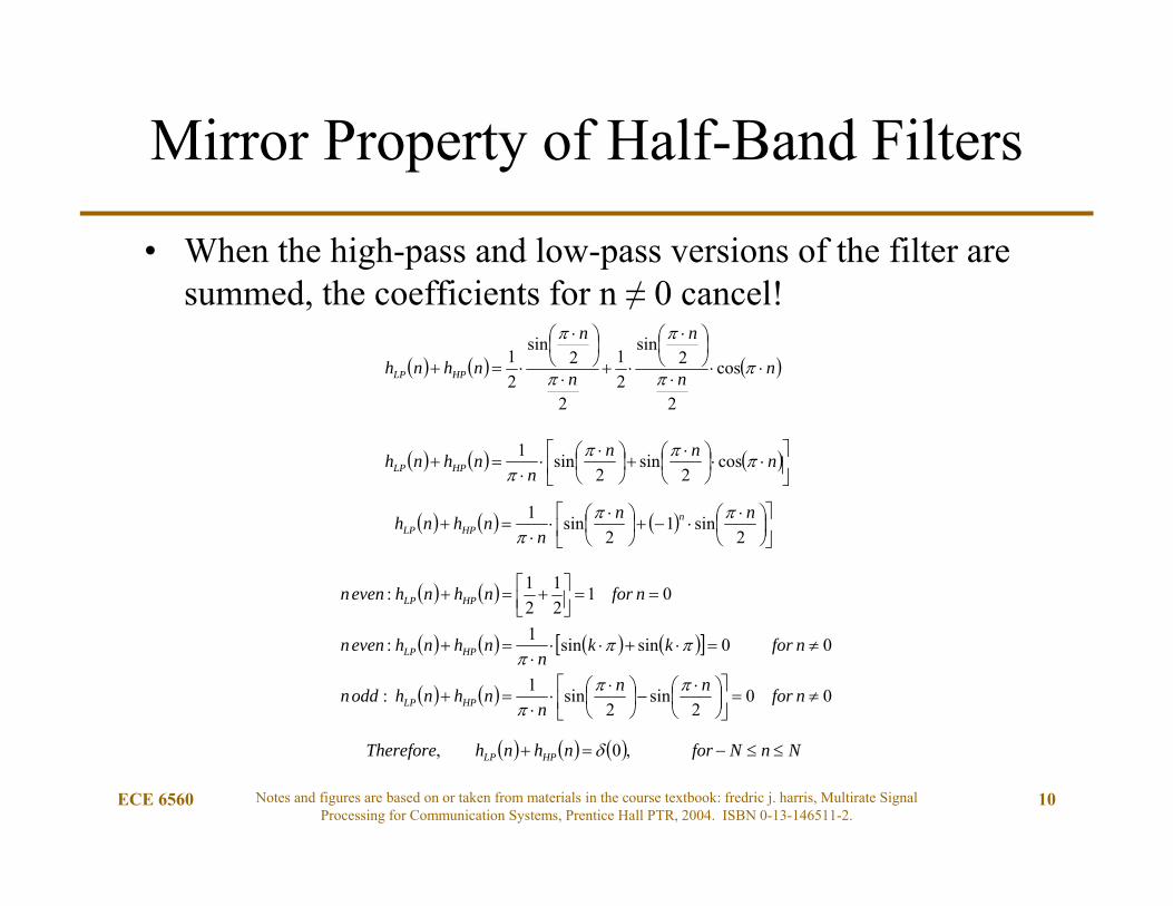
Mirror Property of Half-Band Filters
• When the high-pass and low-pass versions of the filter are summed, the coefficients for n ≠ 0 cancel!
nn
n
n
n
nhnh HPLP
cos
2
2sin
21
2
2sin
21
nnnn
nhnh HPLP
cos2
sin2
sin1
2
sin12
sin1 nnn
nhnh nHPLP
002
sin2
sin1:
00sinsin1:
0121
21:
nfornnn
nhnhoddn
nforkkn
nhnhevenn
nfornhnhevenn
HPLP
HPLP
HPLP
NnNfornhnhTherefore HPLP ,0,

ECE 6560 Notes and figures are based on or taken from materials in the course textbook: fredric j. harris, Multirate Signal Processing for Communication Systems, Prentice Hall PTR, 2004. ISBN 0-13-146511-2.
11
For a Causal Half-Band
• For causality in the sample domain, the entire filter is time shifted by a factor of N (or 2M+1)
• The resulting filter summation is
NnforNnnhnh HPLP 20,
Chap8_3.m

ECE 6560 Notes and figures are based on or taken from materials in the course textbook: fredric j. harris, Multirate Signal Processing for Communication Systems, Prentice Hall PTR, 2004. ISBN 0-13-146511-2.
12
Window Design of Half-Band Filter
• Windowing provides additional side-lobe attenuation– Kaiser windowing– FirPM windowing
nwn
n
nhLP
2
2sin
21
;8.5,1*2*.2:sinc*5.0
NkaiserNNnhLP
;1*2_*.2:sinc*5.0
NwindowremezNNnhLP
Chap8_4.mPassband narrowsRipple decreases
Stopband improves

ECE 6560 Notes and figures are based on or taken from materials in the course textbook: fredric j. harris, Multirate Signal Processing for Communication Systems, Prentice Hall PTR, 2004. ISBN 0-13-146511-2.
13
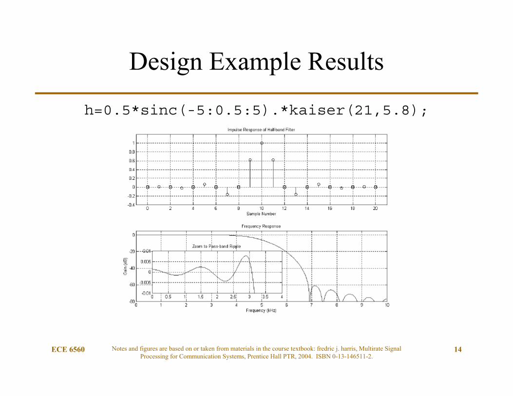
Design Example 8.1
Design a half-band, kaiser windowed filter• Sample Rate 20 kHz• Transition BW 4 kHz (20% of Fs)• Out-of-Band Attenuation 60 dB
The parameter β of the Kaiser window is estimated from Figure 3.8 of chapter 3 to be = 5.8
The estimated filter length is obtained from (3.11) is N=19, but 21 was used. (Note: zero coefficients!)
Chap8_5.m
ECE 6560 Notes and figures are based on or taken from materials in the course textbook: fredric j. harris, Multirate Signal Processing for Communication Systems, Prentice Hall PTR, 2004. ISBN 0-13-146511-2.
14
Design Example Results
h=0.5*sinc(-5:0.5:5).*kaiser(21,5.8);

ECE 6560 Notes and figures are based on or taken from materials in the course textbook: fredric j. harris, Multirate Signal Processing for Communication Systems, Prentice Hall PTR, 2004. ISBN 0-13-146511-2.
15
Design Example 8.1 Repeated
Design a half-band, remez windowed filter• Sample Rate 20 kHz• Transition BW 4 kHz• Out-of-Band Attenuation 60 dB
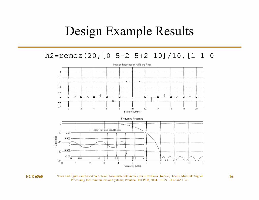
h2=remez(20,[0 5-2 5+2 10]/10,[1 1 0 0],[1 1]);
Note: Zeros should be forced.
• Matlab has computation round-off; therefore, the zeros may be very small values after filter generation.
• Correct them by forcing the appropriate coefficients to zero.
ECE 6560 Notes and figures are based on or taken from materials in the course textbook: fredric j. harris, Multirate Signal Processing for Communication Systems, Prentice Hall PTR, 2004. ISBN 0-13-146511-2.
16
Design Example Results
h2=remez(20,[0 5-2 5+2 10]/10,[1 1 0 0],[1 1]);

ECE 6560 Notes and figures are based on or taken from materials in the course textbook: fredric j. harris, Multirate Signal Processing for Communication Systems, Prentice Hall PTR, 2004. ISBN 0-13-146511-2.
17
Half-Band Remez Design Trick
• Can only the non-zero coefficients be generated? Yes.
h3a=remez(9, [0 5-2 5 5]/5, [1 1 0 0]);
h3 = zeros(1, 21);
h3(2:2:21)=0.5*h3a;
h3(10)=0.5;
Chap8_6.m
Interpolate the no-zeros filter by 2 and add the “center tap”.
The sum of two filters!

ECE 6560 Notes and figures are based on or taken from materials in the course textbook: fredric j. harris, Multirate Signal Processing for Communication Systems, Prentice Hall PTR, 2004. ISBN 0-13-146511-2.
18
Base Filter Responses
h3a=remez(9, [0 5-2 5 5]/5, [1 1 0 0]);
ECE 6560 Notes and figures are based on or taken from materials in the course textbook: fredric j. harris, Multirate Signal Processing for Communication Systems, Prentice Hall PTR, 2004. ISBN 0-13-146511-2.
19
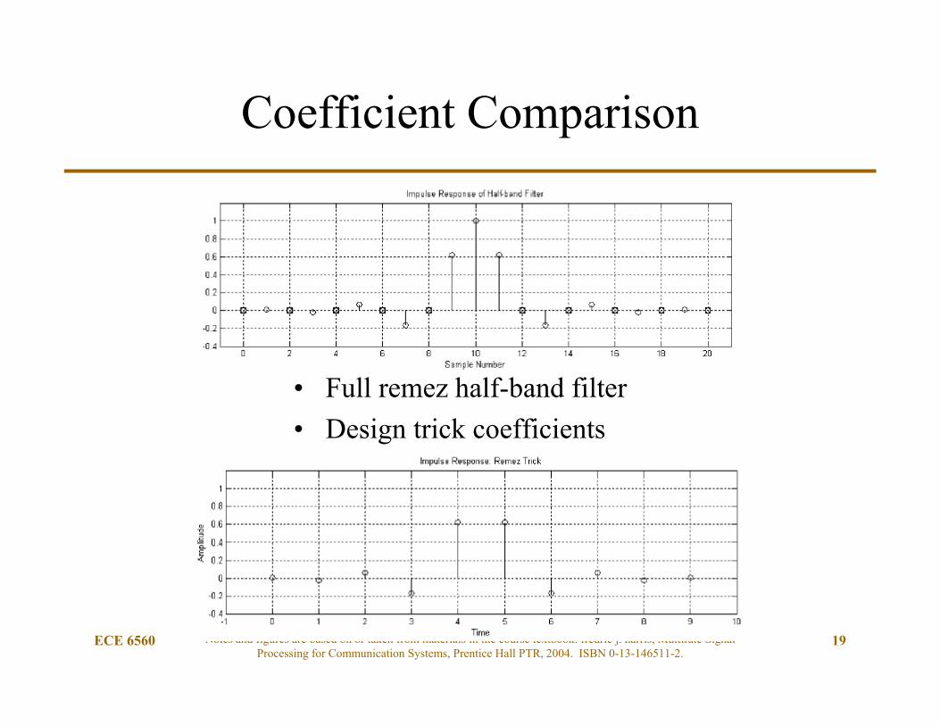
Coefficient Comparison
• Full remez half-band filter• Design trick coefficients

Thoughts on the Trick
• The initial “trick” filter is interpolated by 2 with no filtering.– A spectral replica must exist at the high-frequencies– The only way to remove the HF is to have perfect cancellation
• The sum of a delay element.– The unit coefficients provide phase delay.
ECE 6560 Notes and figures are based on or taken from materials in the course textbook: fredric j. harris, Multirate Signal Processing for Communication Systems, Prentice Hall PTR, 2004. ISBN 0-13-146511-2.
20
Chap8_6.m see the final 2 plots

When Windowing, Why use 21 instead of 19?
• The windows are different!
• For a 21 tap filter, w(1) and w(21) are multiplied by zero– We still must convolve in the frequency domain,
but the two windows are actually different.
• Selecting the “best window” means using 21 taps, not 19 taps.
• Note that the firpm filter is identical for 19 and 21. (4k-1 [or 4k+3] versus 4k+1 [or 4k+5])
ECE 6560 Notes and figures are based on or taken from materials in the course textbook: fredric j. harris, Multirate Signal Processing for Communication Systems, Prentice Hall PTR, 2004. ISBN 0-13-146511-2.
21

ECE 6560 Notes and figures are based on or taken from materials in the course textbook: fredric j. harris, Multirate Signal Processing for Communication Systems, Prentice Hall PTR, 2004. ISBN 0-13-146511-2.
22
Hilbert Transform Band-Pass Filter
• Could we keep just the positive frequency segment of the spectrum?– Real signal are conjugate symmetric, therefore the output would
have to be complex!
• Forming the Hilbert Transform using a half-band filter
2exp nihnh LPHT 2exp
2
2sin
21
nin
n
nhHP
Chap8_7.m

Why we might want this?
• Create an “analytic” signal– Only have positive frequency elements
• Easier to perform some functions on complex signals instead of a real signals– AM demodulation, FM demodulation– SSB signals
• If you want to decimate a complex signal• Complex to real conversion
– What happens when you take the real part of a complex signal?– What happens to the Nyquist frequency bound … it must change!
ECE 6560 Notes and figures are based on or taken from materials in the course textbook: fredric j. harris, Multirate Signal Processing for Communication Systems, Prentice Hall PTR, 2004. ISBN 0-13-146511-2.
23

ECE 6560 Notes and figures are based on or taken from materials in the course textbook: fredric j. harris, Multirate Signal Processing for Communication Systems, Prentice Hall PTR, 2004. ISBN 0-13-146511-2.
24
Hilbert Transform Band-Pass Filter
2exp4
2exp
nihnFF
ihnh LPs
sLPHT
ninn
n
nhHP 2sin
2cos
2
2sin
21
.....,1,,1,,1,,12exp iiiini
• Mix the filter by a complex carrier at Fs/4– Alternating sequence for mixing: even coefficients real, odd imaginary– Half-band filter zeros: odd coefficients exist, even coef are 0 except for h(0)

ECE 6560 Notes and figures are based on or taken from materials in the course textbook: fredric j. harris, Multirate Signal Processing for Communication Systems, Prentice Hall PTR, 2004. ISBN 0-13-146511-2.
25
Hilbert Transform Coefficients
• Resolving the even and odd samples in n
ninn
n
nhHT 2sin
2cos
2
2sin
21
n
inn
n
inhoddn
nnn
n
nhevenn
HT
HT
12
sin
2
2sin
21:
2cos
2
2sin
21:
• One coefficient is real, all others are complex.– Interpretation: the complex filter coefficients cause the negative
portion of the signal spectrum to be cancelled

ECE 6560 Notes and figures are based on or taken from materials in the course textbook: fredric j. harris, Multirate Signal Processing for Communication Systems, Prentice Hall PTR, 2004. ISBN 0-13-146511-2.
26
Hilbert Transform Response
• Notice:– The real and (anti-symmetric) imaginary coefficients– The shifting of the half-band filter spectrum
Chap8_7.m
Chap8_8.m

Application of HB and Hilbertin MRSP
• Filter Decimation (by a factor of 2)– After application, the signal can be decimated by a factor of 2– Real signal HB filtered to Fs/4,
decimate by 2 to allow signal-of-interest to “fill the spectrum”– Complex Signal filtered to positive frequencies 0 to Fs/2,
decimate by by 2 to allow signal-of-interest to “fill the spectrum”
• Filter Interpolation (by a factor of 2)– Interpolate by 2 and apply the filter to remove spectral replicas
ECE 6560 Notes and figures are based on or taken from materials in the course textbook: fredric j. harris, Multirate Signal Processing for Communication Systems, Prentice Hall PTR, 2004. ISBN 0-13-146511-2.
27

Unique Filter Coefficients
• h(0) = 0.5, all other even coefficients h(2n)=0– When decimating by 2, this results in only 1 non-zero coefficient
• h(odd) are non-zero and anti-symmetric– When decimated by 2, this sequence remains
• Two decimation filters h0(n) and h1(n)– h0(n) has one non-zero coefficient, a pure time delay
• Always purely real– h1(n) has all the other coefficients
• For HB they are all purely real• For Hilbert they are all purely imaginary
ECE 6560 Notes and figures are based on or taken from materials in the course textbook: fredric j. harris, Multirate Signal Processing for Communication Systems, Prentice Hall PTR, 2004. ISBN 0-13-146511-2.
28

ECE 6560 Notes and figures are based on or taken from materials in the course textbook: fredric j. harris, Multirate Signal Processing for Communication Systems, Prentice Hall PTR, 2004. ISBN 0-13-146511-2.
29
Applying the Hilbert Transform
• Filter Decimation with the half-band filter.
ECE 6560 Notes and figures are based on or taken from materials in the course textbook: fredric j. harris, Multirate Signal Processing for Communication Systems, Prentice Hall PTR, 2004. ISBN 0-13-146511-2.
30
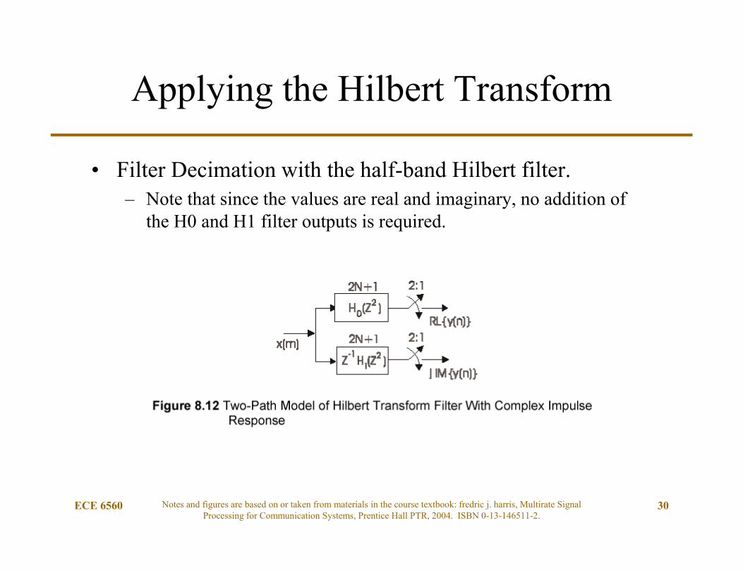
Applying the Hilbert Transform
• Filter Decimation with the half-band Hilbert filter. – Note that since the values are real and imaginary, no addition of
the H0 and H1 filter outputs is required.

ECE 6560 Notes and figures are based on or taken from materials in the course textbook: fredric j. harris, Multirate Signal Processing for Communication Systems, Prentice Hall PTR, 2004. ISBN 0-13-146511-2.
31
Applying Noble Identity
• Simplifying the structure
ECE 6560 Notes and figures are based on or taken from materials in the course textbook: fredric j. harris, Multirate Signal Processing for Communication Systems, Prentice Hall PTR, 2004. ISBN 0-13-146511-2.
32
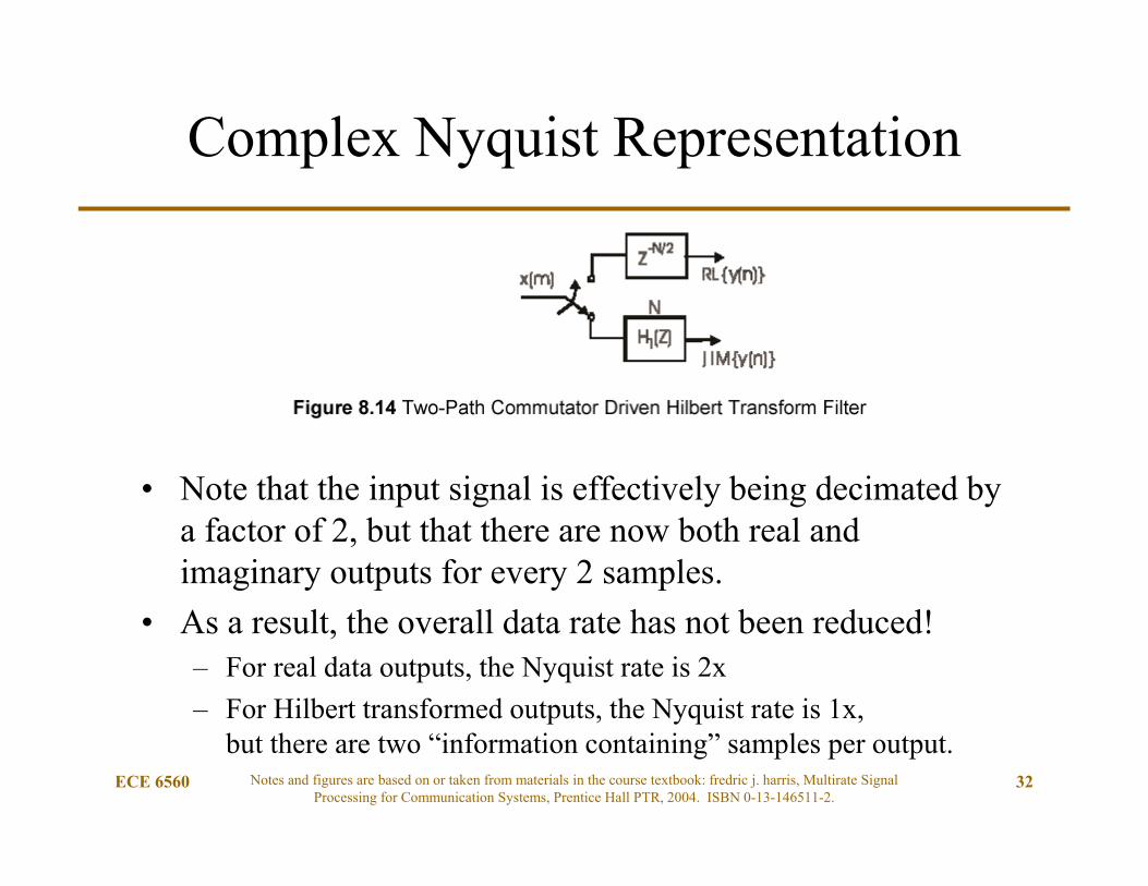
Complex Nyquist Representation
• Note that the input signal is effectively being decimated by a factor of 2, but that there are now both real and imaginary outputs for every 2 samples.
• As a result, the overall data rate has not been reduced!– For real data outputs, the Nyquist rate is 2x– For Hilbert transformed outputs, the Nyquist rate is 1x,
but there are two “information containing” samples per output.

ECE 6560 Notes and figures are based on or taken from materials in the course textbook: fredric j. harris, Multirate Signal Processing for Communication Systems, Prentice Hall PTR, 2004. ISBN 0-13-146511-2.
33
Using Hilbert Transformed Data
• The passband spectrum is centered about fs/4. – Significant attenuation at 0 and fs/2
• Therefore, downconvert a communication signal to be centered at fs/4.
• Perform a Hilbert Transform Half-Band Filter– Only the positive complex spectrum remains
• Process as required– AM: envelope detection I^2+Q^2– FM: mix to baseband and use narrowband derivative function– PM: mix to baseband and extract phase

ECE 6560 Notes and figures are based on or taken from materials in the course textbook: fredric j. harris, Multirate Signal Processing for Communication Systems, Prentice Hall PTR, 2004. ISBN 0-13-146511-2.
34
Interpolating with LP Half-Band Filters

ECE 6560 Notes and figures are based on or taken from materials in the course textbook: fredric j. harris, Multirate Signal Processing for Communication Systems, Prentice Hall PTR, 2004. ISBN 0-13-146511-2.
35
Interpolating
• A standard polyphase interpolation structure

ECE 6560 Notes and figures are based on or taken from materials in the course textbook: fredric j. harris, Multirate Signal Processing for Communication Systems, Prentice Hall PTR, 2004. ISBN 0-13-146511-2.
36
Computation Load (Repeat)
• There is one multiply for every unique coefficient– Conventional filter
• 4M-taps 4M Multiplies, 4M-1 Adds– Half-Band filter
• 4M+3 taps 2M+3 Multiplies, 2M+2 Adds– Half-Band filter, if h(0) doesn’t require a multiply,
• 4M+3 taps 2M+2 Multiplies, 2M+2 Adds– Half-Band filter, if h(0) doesn’t require a multiply and symmetric,
• 4M+3 taps M+1 Multiplies, M+M+1 Adds
– Potential savings: approximately ¼ the multiplies and ½ the adds!
ECE 6560 Notes and figures are based on or taken from materials in the course textbook: fredric j. harris, Multirate Signal Processing for Communication Systems, Prentice Hall PTR, 2004. ISBN 0-13-146511-2.
37
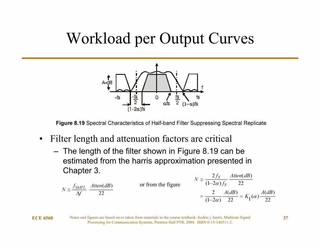
Workload per Output Curves
• Filter length and attenuation factors are critical– The length of the filter shown in Figure 8.19 can be
estimated from the harris approximation presented in Chapter 3.
or from the figure

ECE 6560 Notes and figures are based on or taken from materials in the course textbook: fredric j. harris, Multirate Signal Processing for Communication Systems, Prentice Hall PTR, 2004. ISBN 0-13-146511-2.
38
Filter Tap Estimation
The closer to fs/2, the more
taps are required.

ECE 6560 Notes and figures are based on or taken from materials in the course textbook: fredric j. harris, Multirate Signal Processing for Communication Systems, Prentice Hall PTR, 2004. ISBN 0-13-146511-2.
39
Dyadic Half-Band Filters
• We now consider the use of a cascade of half-band filters to obtain a sample rate increase of any power of 2 such as increase by 8 or by 16.
• Suppose, for instance, we want to increase the sample rate of an input sequence by a factor 8. We have two primary options available to us. We can use an 8-path polyphase filter to accomplish this task, or we can use a cascade of three half-band filters.

ECE 6560 Notes and figures are based on or taken from materials in the course textbook: fredric j. harris, Multirate Signal Processing for Communication Systems, Prentice Hall PTR, 2004. ISBN 0-13-146511-2.
40
Dyadic Half-Band Filters
• We first examine the workload for the sequence of half-band filters and then compare this workload to the M-path filter. – The sequence of half-band filters operates at successively higher
sample rates but with transfer functions that have successively wider transition bandwidths.
– There is a processing advantage to the cascade when the reduction in processing due to the wider transition bandwidth in successive filter stages compensates for operating the consecutive filter stages at successively higher sample rates.

ECE 6560 Notes and figures are based on or taken from materials in the course textbook: fredric j. harris, Multirate Signal Processing for Communication Systems, Prentice Hall PTR, 2004. ISBN 0-13-146511-2.
41
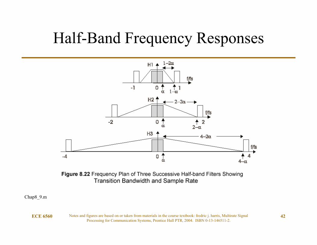
Cascaded Half-Band Interpolation
• With each successive stage, the Half-Band Filter frequency responses can vary.– Notice that the desired passband becomes relatively smaller as the
sample rate increases. This allows the fractional bandwidth, alpha () to be continuously decreasing and the filter sizes getting shorter.
ECE 6560 Notes and figures are based on or taken from materials in the course textbook: fredric j. harris, Multirate Signal Processing for Communication Systems, Prentice Hall PTR, 2004. ISBN 0-13-146511-2.
42
Half-Band Frequency Responses
Chap8_9.m
ECE 6560 Notes and figures are based on or taken from materials in the course textbook: fredric j. harris, Multirate Signal Processing for Communication Systems, Prentice Hall PTR, 2004. ISBN 0-13-146511-2.
43
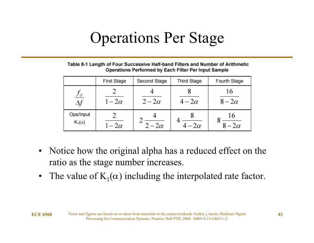
Operations Per Stage
• Notice how the original alpha has a reduced effect on the ratio as the stage number increases.
• The value of K1() including the interpolated rate factor.

Operations Per Stage Example
• Let = 45%
ECE 6560 Notes and figures are based on or taken from materials in the course textbook: fredric j. harris, Multirate Signal Processing for Communication Systems, Prentice Hall PTR, 2004. ISBN 0-13-146511-2.
44
First Stage
Second Stage
Third Stage
Forth Stage
fs/f 20 3.64 2.58 2.68Ops/Input 20 7.27 10.32 21.41Ops Sum 20 27.27 37.59 59
• Let = 40%First Stage
Second Stage
Third Stage
Forth Stage
fs/f 10 3.33 2.5 2.22Ops/Input 10 6.67 10 17.78Ops Sum 10 16.67 26.67 44.45

ECE 6560 Notes and figures are based on or taken from materials in the course textbook: fredric j. harris, Multirate Signal Processing for Communication Systems, Prentice Hall PTR, 2004. ISBN 0-13-146511-2.
45
Operations per Output
• Proportionality factors based on interpolation stages

ECE 6560 Notes and figures are based on or taken from materials in the course textbook: fredric j. harris, Multirate Signal Processing for Communication Systems, Prentice Hall PTR, 2004. ISBN 0-13-146511-2.
46
Proportionality Factor Curves

ECE 6560 Notes and figures are based on or taken from materials in the course textbook: fredric j. harris, Multirate Signal Processing for Communication Systems, Prentice Hall PTR, 2004. ISBN 0-13-146511-2.
47
M-path Polyphase Interpolation
For comparison, we can use an M-path polyphase filter to change the sample rate by a factor of M. We can recast equations (8.16) and (8.17) for the M-path filter to obtain (8.18).
As shown in (8.19) we can determine the length of each path of the M-path filter by distributing the N weights over the M-paths. If we assume that the top path, path-0, of the M-path filter contains only delays, then only (M-1) of the paths contributes to the workload and removing one of the M-paths from the workload estimate reduces the average workload. This scaled workload is shown in (8.20). Figure 8.24 presents graphical representations of (8.18) and (8.20).

ECE 6560 Notes and figures are based on or taken from materials in the course textbook: fredric j. harris, Multirate Signal Processing for Communication Systems, Prentice Hall PTR, 2004. ISBN 0-13-146511-2.
48
Conventional Polyphase Curves

ECE 6560 Notes and figures are based on or taken from materials in the course textbook: fredric j. harris, Multirate Signal Processing for Communication Systems, Prentice Hall PTR, 2004. ISBN 0-13-146511-2.
49
Cascaded (K2) vs. Conventional (K4)
• Cascaded becomes more efficient at higher Rate Changes!

Selecting Approach
• Polyphase Filter Implementation– Single structure or implementation– Small initial alpha
• Cascaded Half-Band Filters– Multiple Stages– Large alpha high rate change
ECE 6560 Notes and figures are based on or taken from materials in the course textbook: fredric j. harris, Multirate Signal Processing for Communication Systems, Prentice Hall PTR, 2004. ISBN 0-13-146511-2.
50
In general, evaluate both methods to see which is more appropriate!

Half-band Interpolation
• Interpolate Filter
• M= 2 Interpolate Filter Polyphase
ECE 6560 Notes and figures are based on or taken from materials in the course textbook: fredric j. harris, Multirate Signal Processing for Communication Systems, Prentice Hall PTR, 2004. ISBN 0-13-146511-2.
51

Half-band Decimation
• Filter Decimate
• M=2 Decimating Polyphase Filter
ECE 6560 Notes and figures are based on or taken from materials in the course textbook: fredric j. harris, Multirate Signal Processing for Communication Systems, Prentice Hall PTR, 2004. ISBN 0-13-146511-2.
52

Half-band Polyphase Decimation and Interpolation
• Can you build MATLAB code that does this?– “brute force versus polyphase”– filter tap lengths change due to bandwidths
ECE 6560 Notes and figures are based on or taken from materials in the course textbook: fredric j. harris, Multirate Signal Processing for Communication Systems, Prentice Hall PTR, 2004. ISBN 0-13-146511-2.
53
A Cascade of M=2 Polyphase
Filters


![WIDEBAND FINGERPRINT DEMODULATION VIA BI-DIMENSIONAL ...ece-research.unm.edu/bsanthan/publications/ASIL-16b.pdf · multirate frequency transformation (MFT) approach [1, 4] that can](https://static.fdocuments.us/doc/165x107/5f6cd3b23f387f3d984061d7/wideband-fingerprint-demodulation-via-bi-dimensional-ece-multirate-frequency.jpg)