ECE 238L Computer Logic Design Spring 2010 Lab -1 Introduction to Discrete Digital Logic 01/25/101.
12
ECE 238L Computer Logic Design Spring 2010 Lab -1 Introduction to Discrete Digital Logic 01/25/10 1
-
Upload
martin-reaver -
Category
Documents
-
view
223 -
download
2
Transcript of ECE 238L Computer Logic Design Spring 2010 Lab -1 Introduction to Discrete Digital Logic 01/25/101.
ECE 238L Computer Logic DesignSpring 2010
Lab -1
Introduction to
Discrete Digital Logic
01/25/10 1
01/25/10 2
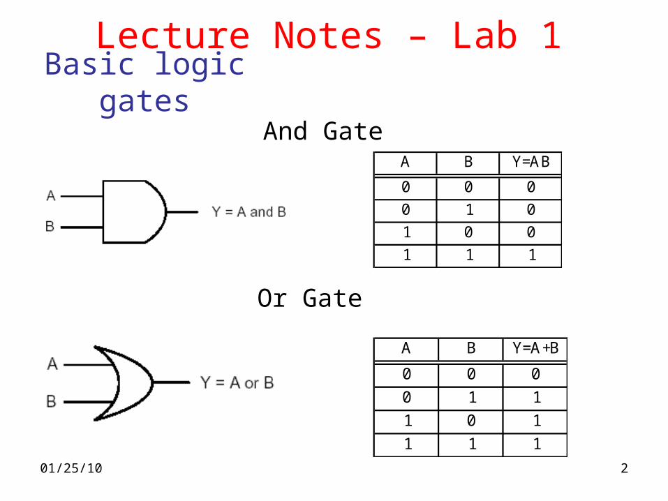
Basic logic gates
And Gate
Or Gate
A B Y=A+B
0 0 0
0 1 1
1 0 1
1 1 1
A B Y=AB
0 0 0
0 1 0
1 0 0
1 1 1
Lecture Notes – Lab 1
01/25/10 3
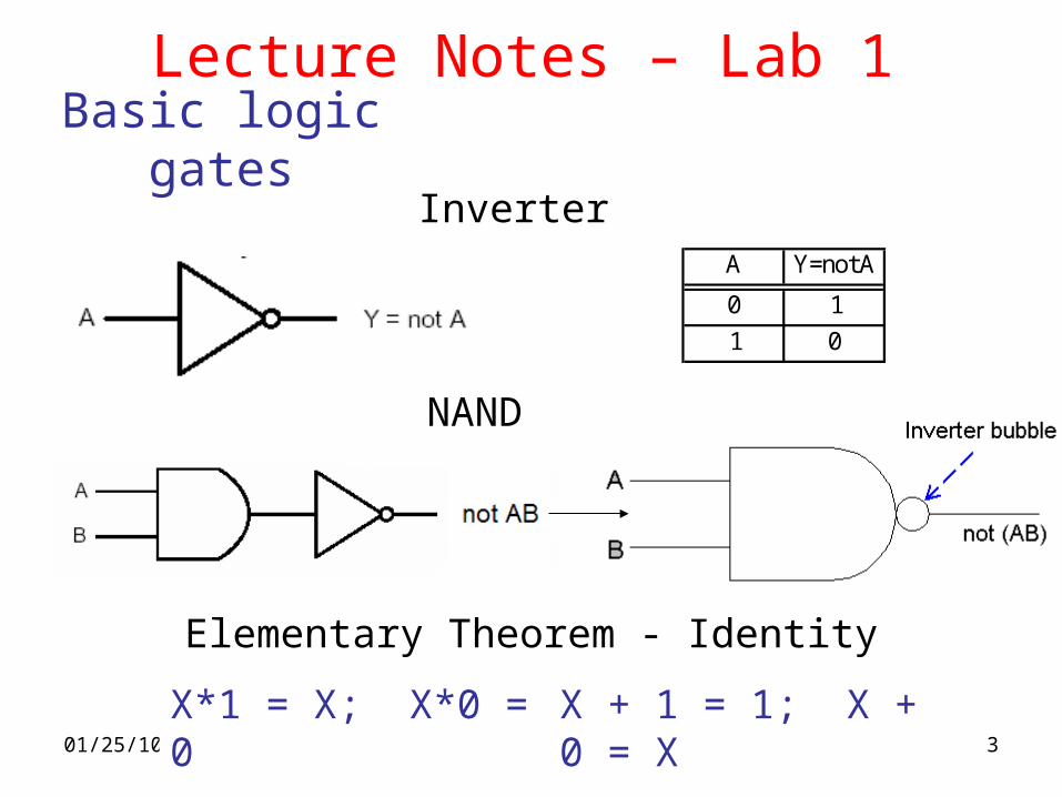
InverterA Y=notA
0 1
1 0
Elementary Theorem - Identity
X*1 = X; X*0 = 0 X + 1 = 1; X + 0 = X
NAND
Lecture Notes – Lab 1Basic logic gates
01/25/10 4
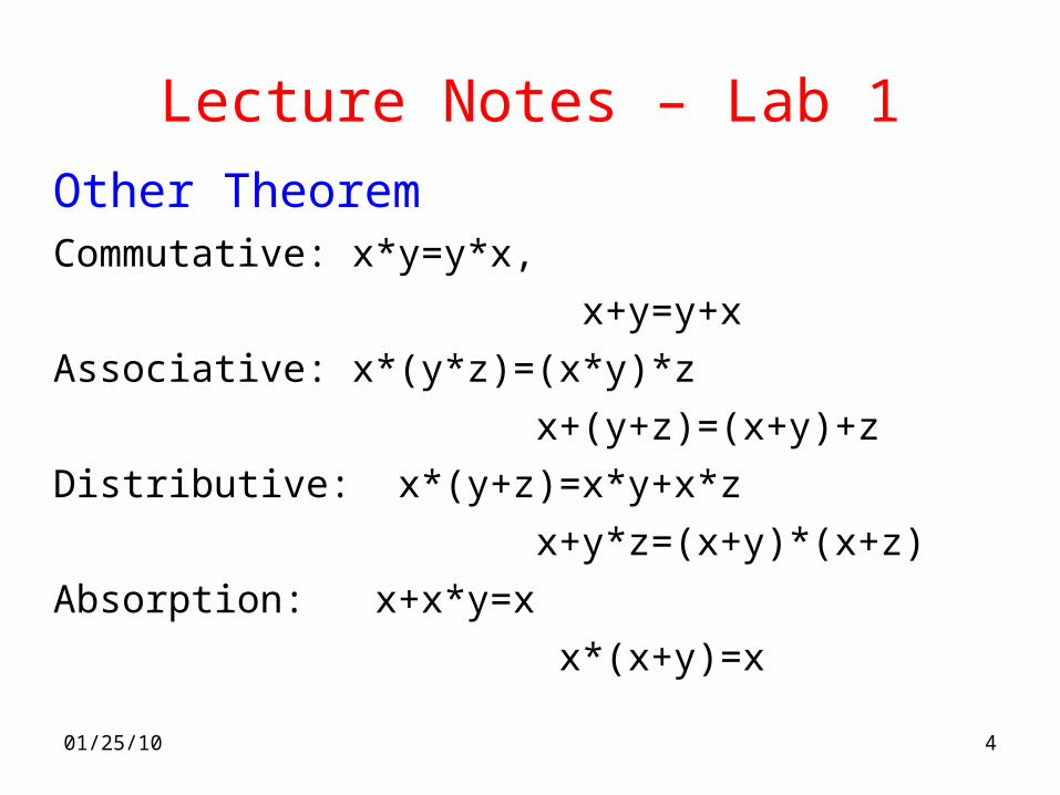
Lecture Notes – Lab 1Other TheoremCommutative: x*y=y*x,
x+y=y+x
Associative: x*(y*z)=(x*y)*z
x+(y+z)=(x+y)+z
Distributive: x*(y+z)=x*y+x*z
x+y*z=(x+y)*(x+z)
Absorption: x+x*y=x
x*(x+y)=x

01/25/10 5
Lecture Notes – Lab 1Other TheoremCombining: x*y+x*y'=x,
(x+y)(x+y')=x
DeMorgan's theorem:(x*y)'=x'+y'
(x+y)'=x'+y'
x+x'y=x+y
x(x'+y)=xy
Consensus: xy+yz+x'z=xy+x'z
(x+y)(y+z)(x'+z)=(x+y)(x'+z)
01/25/10 6
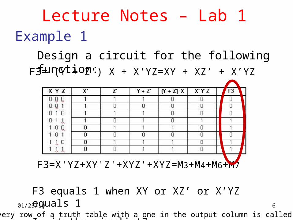
F3= (Y + Z') X + X'YZ=XY + XZ’ + X’YZ
Design a circuit for the following function:
F3=X'YZ+XY'Z'+XYZ'+XYZ=M3+M4+M6+M7
F3 equals 1 when XY or XZ’ or X’YZ equals 1
Is it the simplist?
Example 1
Lecture Notes – Lab 1
Note: every row of a truth table with a one in the output column is called a minterm
01/25/10 7
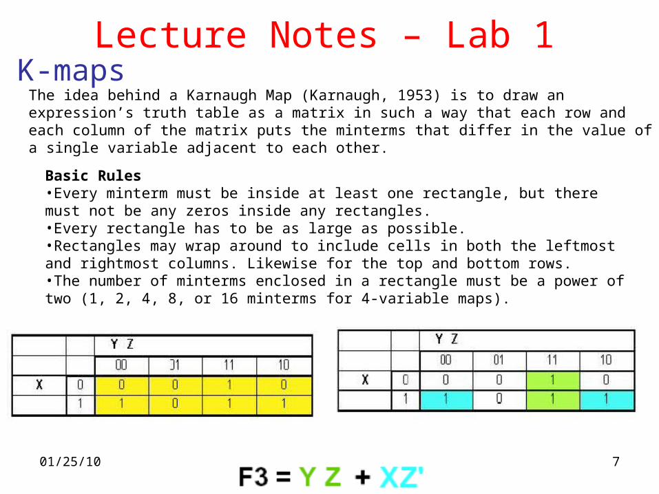
K-mapsLecture Notes – Lab 1
The idea behind a Karnaugh Map (Karnaugh, 1953) is to draw an expression’s truth table as a matrix in such a way that each row and each column of the matrix puts the minterms that differ in the value of a single variable adjacent to each other.
Basic Rules•Every minterm must be inside at least one rectangle, but there must not be any zeros inside any rectangles. •Every rectangle has to be as large as possible. •Rectangles may wrap around to include cells in both the leftmost and rightmost columns. Likewise for the top and bottom rows. •The number of minterms enclosed in a rectangle must be a power of two (1, 2, 4, 8, or 16 minterms for 4-variable maps).
01/25/10 8
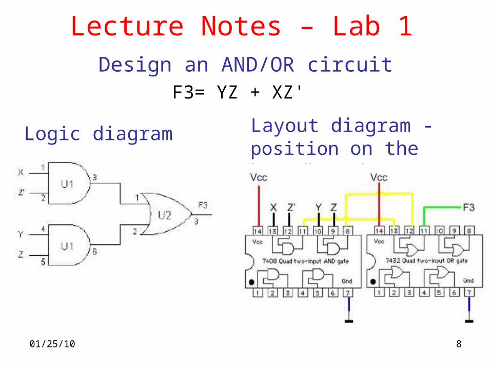
F3= YZ + XZ'
Logic diagram Layout diagram - position on the breadboard
Design an AND/OR circuit
Lecture Notes – Lab 1
01/25/10 9
Lecture Notes – Lab 1
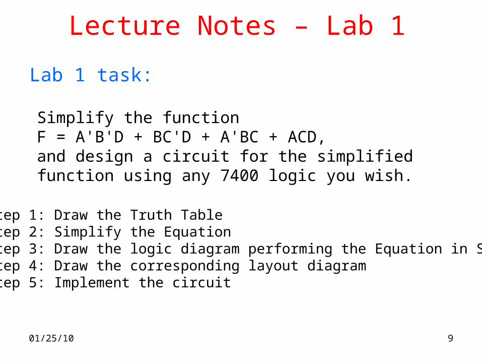
Simplify the function F = A'B'D + BC'D + A'BC + ACD,and design a circuit for the simplified function using any 7400 logic you wish.
Step 1: Draw the Truth TableStep 2: Simplify the EquationStep 3: Draw the logic diagram performing the Equation in Step 2Step 4: Draw the corresponding layout diagramStep 5: Implement the circuit
Lab 1 task:
01/25/10 10
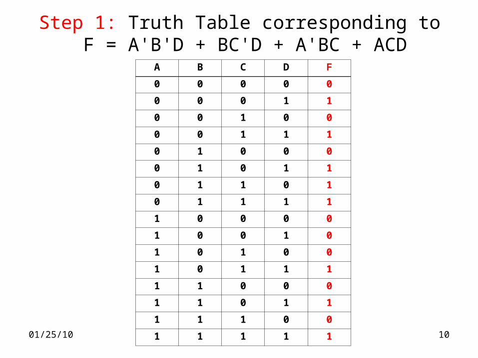
Step 1: Truth Table corresponding to F = A'B'D + BC'D + A'BC + ACD
A B C D F
0 0 0 0 0
0 0 0 1 1
0 0 1 0 0
0 0 1 1 1
0 1 0 0 0
0 1 0 1 1
0 1 1 0 1
0 1 1 1 1
1 0 0 0 0
1 0 0 1 0
1 0 1 0 0
1 0 1 1 1
1 1 0 0 0
1 1 0 1 1
1 1 1 0 0
1 1 1 1 1
01/25/10 11
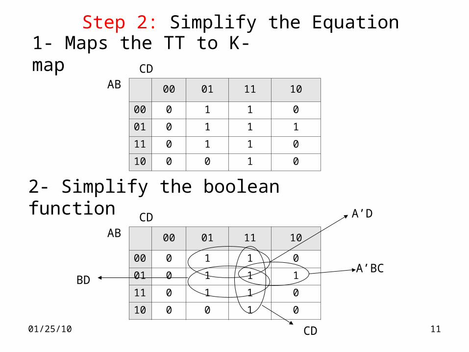
Step 2: Simplify the Equation1- Maps the TT to K-map
2- Simplify the boolean function
00 01 11 10
00 0 1 1 0
01 0 1 1 1
11 0 1 1 0
10 0 0 1 0
ABCD
00 01 11 10
00 0 1 1 0
01 0 1 1 1
11 0 1 1 0
10 0 0 1 0
ABCD
BD
A’D
CD
A’BC
01/25/10 12
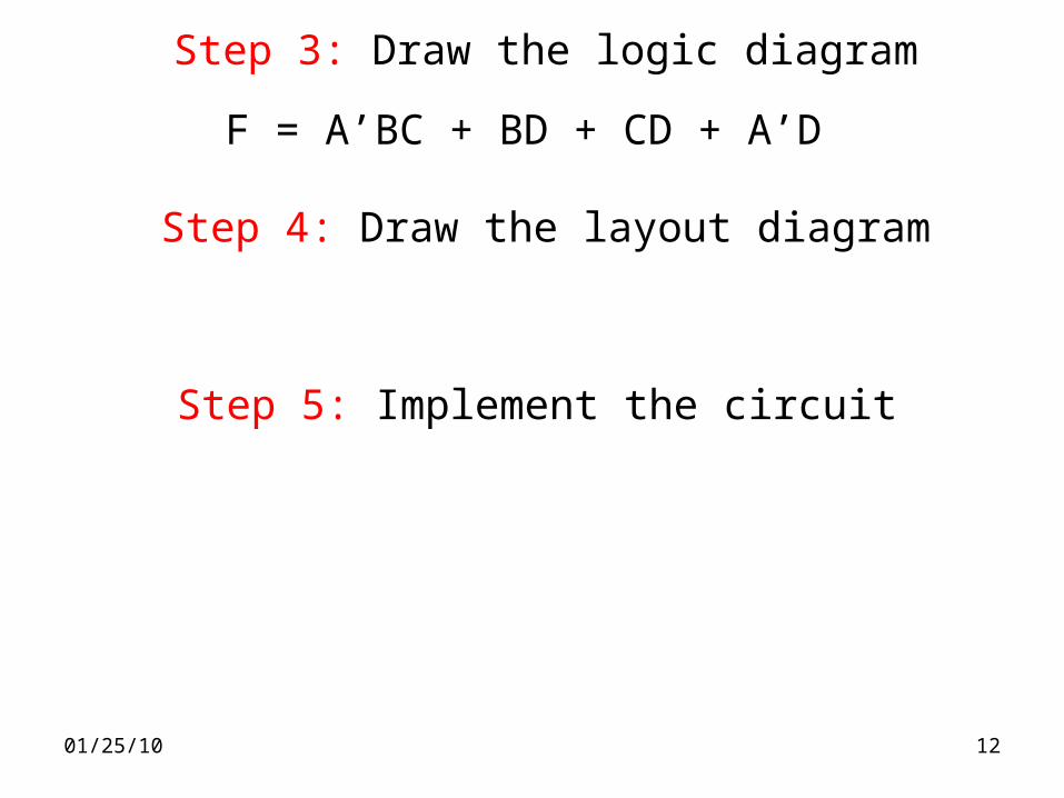
Step 3: Draw the logic diagram
F = A’BC + BD + CD + A’D
Step 4: Draw the layout diagram
Step 5: Implement the circuit