
ECAM Ethernet communications adapter module Modbus ... · 4 Instruction Booklet IL0131127EN...
36
Instruction Leaflet IL0131127EN Effective October 2018 Contents Description Page 1 Introduction 2 11 Reference documents 2 12 Definitions 2 2 Modbus communications 2 21 Modbus TCP 2 22 Modbus RTU via USB 2 23 Modbus function codes 2 24 Modbus slave/device address 2 ECAM Ethernet communications adapter module Modbus reference manual PXR-ECAM – MTCP: ethernet communication adapter module with Modbus TCP/IP Description Page 25 Register number vs register address 2 26 Exception codes 2 3 Modbus register map 3 31 Real-time data object registers 3 32 Input status (discrete inputs) 8 33 Setpoint registers 8 34 Event registers 26 Figure 1. Left = front view, right = side view CAM-PXR Link 24 VDC Mounting foot CAM expansion port USB conf port CAM-PXR link status LED Power Ok status Ethernet E1 w link/speed LEDs Ethernet E2 w link/speed LEDs DIN Relay CAM-Link Status Mounting foot Spring clip 99 mm (39”) 18 mm (71”) 35 mm (14”) DIN rail mount
Transcript of ECAM Ethernet communications adapter module Modbus ... · 4 Instruction Booklet IL0131127EN...

Instruction Leaflet IL0131127EN Effective October 2018
ContentsDescription Page
1 Introduction . . . . . . . . . . . . . . . . . . . . . . . . . . . . 21 .1 Reference documents . . . . . . . . . . . . . . . . . 21 .2 Definitions . . . . . . . . . . . . . . . . . . . . . . . . . . 2
2 Modbus communications . . . . . . . . . . . . . . . . . . 22 .1 Modbus TCP . . . . . . . . . . . . . . . . . . . . . . . . . 22 .2 Modbus RTU via USB . . . . . . . . . . . . . . . . . 22 .3 Modbus function codes . . . . . . . . . . . . . . . . 22 .4 Modbus slave/device address . . . . . . . . . . . 2
ECAM Ethernet communications adapter moduleModbus reference manual
PXR-ECAM – MTCP: ethernet communication adapter module with Modbus TCP/IP
Description Page
2 .5 Register number vs . register address . . . . . 22 .6 Exception codes . . . . . . . . . . . . . . . . . . . . . . 2
3 Modbus register map . . . . . . . . . . . . . . . . . . . . . 33 .1 Real-time data object registers . . . . . . . . . . 3
3 .2 Input status (discrete inputs) . . . . . . . . . . 83 .3 Setpoint registers . . . . . . . . . . . . . . . . . . . . . 83 .4 Event registers . . . . . . . . . . . . . . . . . . . . . . 26
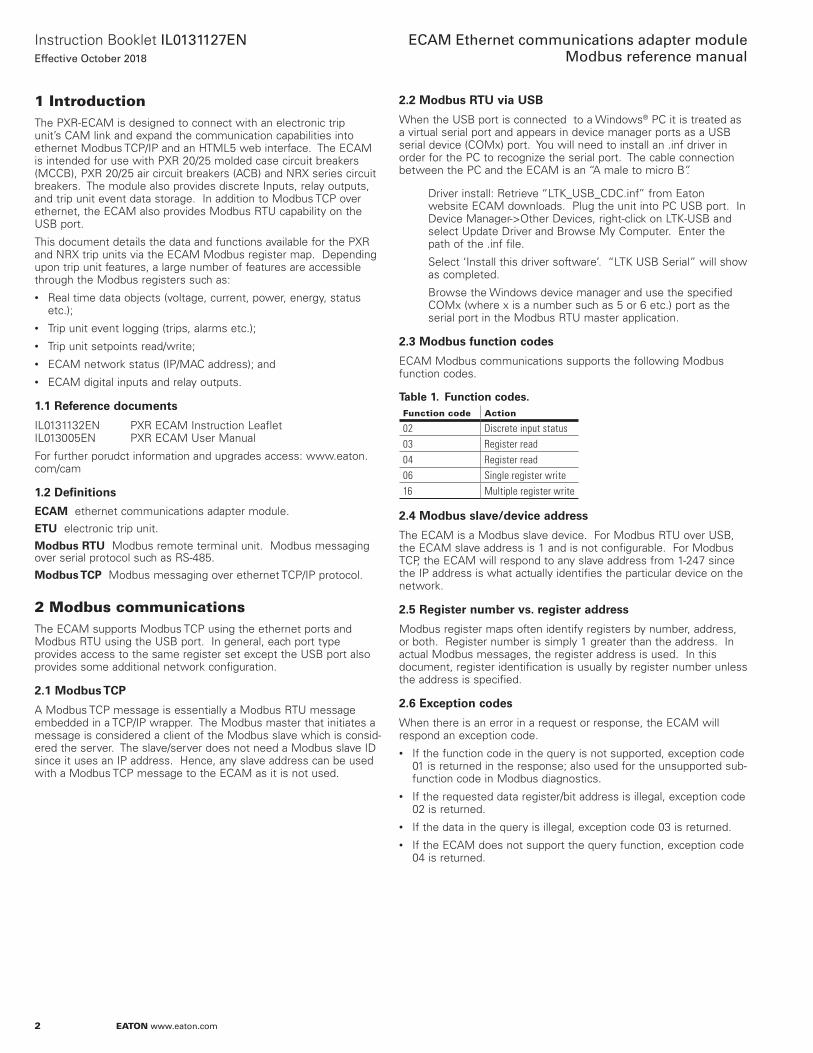
Figure 1. Left = front view, right = side view
CAM-PXR Link 24 VDC Mounting foot
CAM expansion port
USB conf . port
CAM-PXR link status LED
Power Ok status
Ethernet E1 w link/speed LEDs
Ethernet E2 w link/speed LEDs
DIN Relay
CAM-Link Status
Mounting foot
Spring clip
99 mm (3 .9”)
18 mm ( .71”)
35 mm (1 .4”)DIN rail mount
2
Instruction Booklet IL0131127ENEffective October 2018
ECAM Ethernet communications adapter module Modbus reference manual
EATON www.eaton.com
1 IntroductionThe PXR-ECAM is designed to connect with an electronic trip unit’s CAM link and expand the communication capabilities into ethernet Modbus TCP/IP and an HTML5 web interface . The ECAM is intended for use with PXR 20/25 molded case circuit breakers (MCCB), PXR 20/25 air circuit breakers (ACB) and NRX series circuit breakers . The module also provides discrete Inputs, relay outputs, and trip unit event data storage . In addition to Modbus TCP over ethernet, the ECAM also provides Modbus RTU capability on the USB port .
This document details the data and functions available for the PXR and NRX trip units via the ECAM Modbus register map . Depending upon trip unit features, a large number of features are accessible through the Modbus registers such as:• Real time data objects (voltage, current, power, energy, status
etc .);• Trip unit event logging (trips, alarms etc .);• Trip unit setpoints read/write;• ECAM network status (IP/MAC address); and• ECAM digital inputs and relay outputs .
1.1 Reference documents
IL0131132EN PXR ECAM Instruction Leaflet IL013005EN PXR ECAM User Manual
For further porudct information and upgrades access: www .eaton .com/cam
1.2 Definitions
ECAM ethernet communications adapter module .
ETU electronic trip unit .
Modbus RTU Modbus remote terminal unit . Modbus messaging over serial protocol such as RS-485 .
Modbus TCP Modbus messaging over ethernet TCP/IP protocol .
2 Modbus communicationsThe ECAM supports Modbus TCP using the ethernet ports and Modbus RTU using the USB port . In general, each port type provides access to the same register set except the USB port also provides some additional network configuration .
2.1 Modbus TCP
A Modbus TCP message is essentially a Modbus RTU message embedded in a TCP/IP wrapper . The Modbus master that initiates a message is considered a client of the Modbus slave which is consid-ered the server . The slave/server does not need a Modbus slave ID since it uses an IP address . Hence, any slave address can be used with a Modbus TCP message to the ECAM as it is not used .
2.2 Modbus RTU via USB
When the USB port is connected to a Windows® PC it is treated as a virtual serial port and appears in device manager ports as a USB serial device (COMx) port . You will need to install an .inf driver in order for the PC to recognize the serial port . The cable connection between the PC and the ECAM is an “A male to micro B” .
Driver install: Retrieve “LTK_USB_CDC .inf” from Eaton website ECAM downloads . Plug the unit into PC USB port . In Device Manager->Other Devices, right-click on LTK-USB and select Update Driver and Browse My Computer . Enter the path of the .inf file .
Select ‘Install this driver software’ . “LTK USB Serial” will show as completed .
Browse the Windows device manager and use the specified COMx (where x is a number such as 5 or 6 etc .) port as the serial port in the Modbus RTU master application .
2.3 Modbus function codes
ECAM Modbus communications supports the following Modbus function codes .
Table 1. Function codes.Function code Action
02 Discrete input status03 Register read04 Register read06 Single register write16 Multiple register write
2.4 Modbus slave/device address
The ECAM is a Modbus slave device . For Modbus RTU over USB, the ECAM slave address is 1 and is not configurable . For Modbus TCP, the ECAM will respond to any slave address from 1-247 since the IP address is what actually identifies the particular device on the network .
2.5 Register number vs. register address
Modbus register maps often identify registers by number, address, or both . Register number is simply 1 greater than the address . In actual Modbus messages, the register address is used . In this document, register identification is usually by register number unless the address is specified .
2.6 Exception codes
When there is an error in a request or response, the ECAM will respond an exception code .• If the function code in the query is not supported, exception code
01 is returned in the response; also used for the unsupported sub-function code in Modbus diagnostics .
• If the requested data register/bit address is illegal, exception code 02 is returned .
• If the data in the query is illegal, exception code 03 is returned .• If the ECAM does not support the query function, exception code
04 is returned .
3
Instruction Booklet IL0131127ENEffective October 2018
ECAM Ethernet communications adapter module Modbus reference manual
EATON www.eaton.com
3 Modbus register map3.1 Real-time data object registers
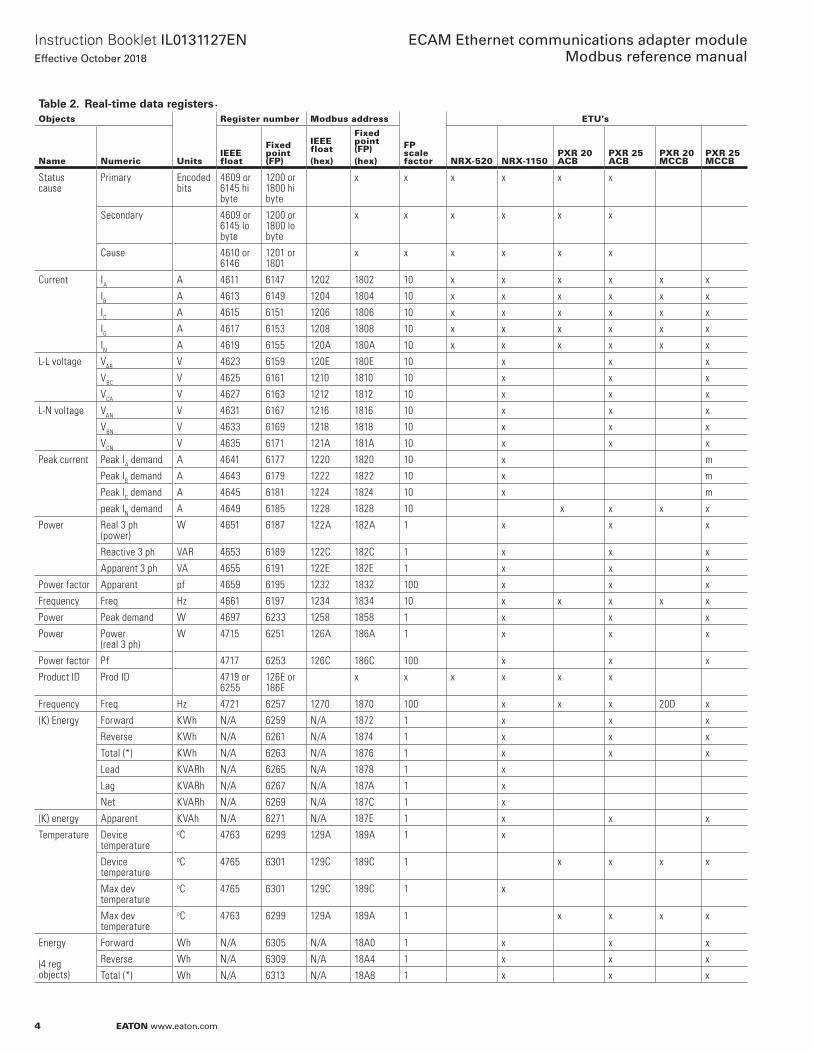
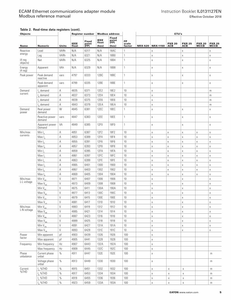
Real-time objects such as current, voltage, power, energy and so on are shown in Table 2 below . Most real-time data can be obtained either in IEEE floating point or in fixed-point format . Energy objects can be only obtained in fixed-point format . For data shown in fixed-point format, each result would be the real-time data multiplied by the scale factor shown in that column .
3.1.1 Energy objects
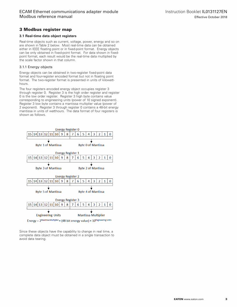
Energy objects can be obtained in two-register fixed-point data format and four-register encoded format but not in floating point format . The two-register format is presented in units of kilowatt-hours .
The four registers encoded energy object occupies register 3 through register 0 . Register 3 is the high order register and register 0 is the low order register . Register 3 high byte contains value corresponding to engineering units (power of 10 signed exponent) . Register 3 low byte contains a mantissa multiplier value (power of 2 exponent) . Register 3 through register 0 contains a 48-bit energy mantissa in units of watthours . The data format of four registers is shown as follows .
Since these objects have the capability to change in real time, a complete data object must be obtained in a single transaction to avoid data tearing .
4
Instruction Booklet IL0131127ENEffective October 2018
ECAM Ethernet communications adapter module Modbus reference manual
EATON www.eaton.com
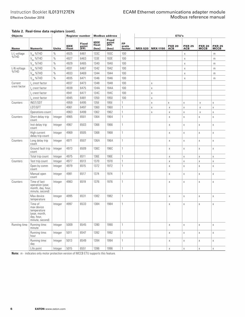
Table 2. Real-time data registers (cont).Objects
Units
Register number Modbus address
FP scale factor
ETU’s
Name NumericIEEEfloat
Fixedpoint(FP)
IEEEfloat (hex)
Fixedpoint (FP)(hex) NRX-520 NRX-1150
PXR 20 ACB
PXR 25 ACB
PXR 20 MCCB
PXR 25 MCCB
Statuscause
Primary Encoded bits
4609 or 6145 hi byte
1200 or 1800 hi byte
x x x x x x
Secondary 4609 or 6145 lo byte
1200 or 1800 lo byte
x x x x x x
Cause 4610 or 6146
1201 or 1801
x x x x x x
Current IA A 4611 6147 1202 1802 10 x x x x x x
IB A 4613 6149 1204 1804 10 x x x x x x
IC A 4615 6151 1206 1806 10 x x x x x x
IG A 4617 6153 1208 1808 10 x x x x x x
IN A 4619 6155 120A 180A 10 x x x x x x
L-L voltage VAB V 4623 6159 120E 180E 10 x x x
VBC V 4625 6161 1210 1810 10 x x x
VCA V 4627 6163 1212 1812 10 x x x
L-N voltage VAN V 4631 6167 1216 1816 10 x x x
VBN V 4633 6169 1218 1818 10 x x x
VCN V 4635 6171 121A 181A 10 x x x
Peak current Peak IA demand A 4641 6177 1220 1820 10 x m
Peak IB demand A 4643 6179 1222 1822 10 x m
Peak IC demand A 4645 6181 1224 1824 10 x m
peak IN demand A 4649 6185 1228 1828 10 x x x x
Power Real 3 ph (power)
W 4651 6187 122A 182A 1 x x x
Reactive 3 ph VAR 4653 6189 122C 182C 1 x x x
Apparent 3 ph VA 4655 6191 122E 182E 1 x x x
Power factor Apparent pf 4659 6195 1232 1832 100 x x x
Frequency Freq Hz 4661 6197 1234 1834 10 x x x x x
Power Peak demand W 4697 6233 1258 1858 1 x x x
Power Power (real 3 ph)
W 4715 6251 126A 186A 1 x x x
Power factor Pf 4717 6253 126C 186C 100 x x x
Product ID Prod ID 4719 or 6255
126E or 186E
x x x x x x
Frequency Freq Hz 4721 6257 1270 1870 100 x x x 20D x
(K) Energy Forward KWh N/A 6259 N/A 1872 1 x x x
Reverse KWh N/A 6261 N/A 1874 1 x x x
Total (*) KWh N/A 6263 N/A 1876 1 x x x
Lead KVARh N/A 6265 N/A 1878 1 x
Lag KVARh N/A 6267 N/A 187A 1 x
Net KVARh N/A 6269 N/A 187C 1 x
(K) energy Apparent KVAh N/A 6271 N/A 187E 1 x x x
Temperature Device temperature
oC 4763 6299 129A 189A 1 x
Device temperature
oC 4765 6301 129C 189C 1 x x x x
Max dev temperature
oC 4765 6301 129C 189C 1 x
Max dev temperature
oC 4763 6299 129A 189A 1 x x x x
Energy (4 reg objects)
Forward Wh N/A 6305 N/A 18A0 1 x x x
Reverse Wh N/A 6309 N/A 18A4 1 x x x
Total (*) Wh N/A 6313 N/A 18A8 1 x x x
.
5
Instruction Booklet IL0131127ENEffective October 2018
ECAM Ethernet communications adapter module Modbus reference manual
EATON www.eaton.com
Table 2. Real-time data registers (cont).Objects
Units
Register number Modbus address
FP scale factor
ETU’s
Name NumericIEEEfloat
Fixedpoint(FP)
IEEEfloat (hex)
Fixedpoint (FP)(hex) NRX-520 NRX-1150
PXR 20 ACB
PXR 25 ACB
PXR 20 MCCB
PXR 25 MCCB
Reactive energy (4 reg objects)
Lead VARh N/A 6317 N/A 18AC 1 x x x
Lag VARh N/A 6321 N/A 18B0 1 x x x
Net VARh N/A 6325 N/A 18B4 1 x x x
Energy (4 reg)
Apparent VAh N/A 6329 N/A 18B8 1 x x x
Peak power Peak demand reactive
vars 4797 6333 12BC 18BC 1 x x x
Peak demand apparent
vars 4799 6335 12BE 18BE 1 x x x
Demandcurrent
IA demand A 4835 6371 12E2 18E2 10 x m
IB demand A 4837 6373 12E4 18E4 10 x m
IC demand A 4839 6375 12E6 18E6 10 x m
IN demand A 4843 6379 12EA 18EA 10 x m
Demandpower
Real power demand
W 4845 6381 12EC 18EC 1 x x x
Reactive power demand
vars 4847 6383 12EE 18EE 1 x x x
Apparent power Demand
VA 4849 6385 12F0 18F0 1 x x x
Min/maxcurrents
Min IA A 4851 6387 12F2 18F2 10 x x x x x
Max IA A 4853 6389 12F4 18F4 10 x x x x x
Min IB A 4855 6391 12F6 18F6 10 x x x x x
Max IB A 4857 6393 12F8 18F8 10 x x x x x
Min IC A 4859 6395 12FA 18FA 10 x x x x x
Max IC A 4861 6397 12FC 18FC 10 x x x x x
Min IG A 4863 6399 12FE 18FE 10 x x x x x
Max IG A 4865 6401 1300 1900 10 x x x x x
Min IN A 4867 6403 1302 1902 10 x x x x x
Max IN A 4869 6405 1304 1904 10 x x x x x
Min/maxL-L voltage
Min VAB V 4871 6407 1306 1906 10 x x x
Max VAB V 4873 6409 1308 1908 10 x x x
Min VBC V 4875 6411 130A 190A 10 x x x
Max VBC V 4877 6413 130C 190C 10 x x x
Min VCA V 4879 6415 130E 190E 10 x x x
Max VCA V 4881 6417 1310 1910 10 x x x
Min/maxL-N voltage
Min VAN V 4883 6419 1312 1912 10 x x x
Max VAN V 4885 6421 1314 1914 10 x x x
Min VBN V 4887 6423 1316 1916 10 x x x
Max VBN V 4889 6425 1318 1918 10 x x x
Min VCN V 4891 6427 131A 191A 10 x x x
Max VCN V 4893 6429 131C 191C 10 x x x
Powerfactor
Min apparent pf 4903 6439 1326 1926 100 x
Max apparent pf 4905 6441 1328 1928 100 x
Frequency
Min frequency Hz 4907 6443 132A 192A 100 x
Max frequency Hz 4909 6445 132C 192C 100 x
Phaseunbalance
Current phase unbal
% 4911 6447 132E 192E 100 x m
Voltage phase unbal
% 4913 6449 1330 1930 100 x m
Current%THD
IA %THD % 4915 6451 1332 1932 100 x x x m
IB %THD % 4917 6453 1334 1934 100 x x x m
IC %THD % 4919 6455 1336 1936 100 x x x m
IN %THD % 4923 6459 133A 193A 100 x x x m
Table 2. Real-time data registers (cont.).
6
Instruction Booklet IL0131127ENEffective October 2018
ECAM Ethernet communications adapter module Modbus reference manual
EATON www.eaton.com
Table 2. Real-time data registers (cont).Objects
Units
Register number Modbus address
FP scale factor
ETU’s
Name NumericIEEEfloat
Fixedpoint(FP)
IEEEfloat (hex)
Fixedpoint (FP)(hex) NRX-520 NRX-1150
PXR 20 ACB
PXR 25 ACB
PXR 20 MCCB
PXR 25 MCCB
L-L voltage%THD
VAB %THD % 4925 6461 133C 193C 100 x m
VBC %THD % 4927 6463 133E 193E 100 x m
VCA %THD % 4929 6465 1340 1940 100 x m
L-N voltage%THD
VAN %THD % 4931 6467 1342 1942 100 x m
VBN %THD % 4933 6469 1344 1944 100 x m
VCN %THD % 4935 6471 1346 1946 100 x m
Currentcrest factor
IA crest factor 4937 6473 1348 1948 100 x
IB crest factor 4939 6475 134A 194A 100 x
IC crest factor 4941 6477 134C 194C 100 x
IN crest factor 4945 6481 1350 1950 100 x Counters INST/SDT 4959 6495 135E 195E 1 x x x x x
LDT/GFT 4961 6497 1360 1960 1 x x x x xOperations count 4963 6499 1362 1962 1 x x x x x
Counters Short delay trip count
Integer 4965 6501 1364 1964 1 x x x x
Inst delay trip count
Integer 4967 6503 1366 1966 1 x x x x
High current delay trip count
Integer 4969 6505 1368 1968 1 x x x x
Counters Long delay trip count
Integer 4971 6507 136A 196A 1 x x x x
Ground fault trip count
Integer 4973 6509 136C 196C 1 x x x x
Total trip count Integer 4975 6511 136E 196E 1 x x x xCounters Test trip count Integer 4977 6513 1370 1970 1 x x x x
Open by comm count
Integer 4979 6515 1372 1972 1 x x x x
Manual open count
Integer 4981 6517 1374 1974 1 x x x x
Counters Time of last operation (year, month, day, hour, minute, second)
Integer 4983 6519 1376 1976 1 x x x x
Max device temperature
Integer 4995 6531 1382 1982 1 x x x x
Time of max device temperature (year, month, day, hour, minute, second)
Integer 4997 6533 1384 1984 1 x x x x
Running time Running time: minute
Integer 5009 6545 1390 1990 1 x x x x
Running time: hour
Integer 5011 6547 1392 1992 1 x x x x
Running time: day
Integer 5013 6549 1394 1994 1 x x x x
Life point Integer 5015 6551 1396 1996 1 x x x x
Note: m - indicates only motor protection version of MCCB ETU supports this feature.
7
Instruction Booklet IL0131127ENEffective October 2018
ECAM Ethernet communications adapter module Modbus reference manual
EATON www.eaton.com
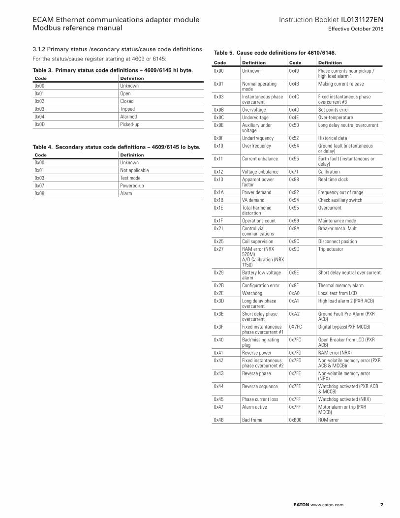
3.1.2 Primary status /secondary status/cause code definitions
For the status/cause register starting at 4609 or 6145:
Table 3. Primary status code definitions – 4609/6145 hi byte.Code Definition
0x00 Unknown0x01 Open 0x02 Closed 0x03 Tripped 0x04 Alarmed0x0D Picked-up
Table 4. Secondary status code definitions – 4609/6145 lo byte.Code Definition
0x00 Unknown0x01 Not applicable0x03 Test mode 0x07 Powered-up0x08 Alarm
Table 5. Cause code definitions for 4610/6146.
Code Definition Code Definition
0x00 Unknown 0x49 Phase currents near pickup / high load alarm 1
0x01 Normal operating mode
0x4B Making current release
0x03 Instantaneous phase overcurrent
0x4C Fixed instantaneous phase overcurrent #3
0x0B Overvoltage 0x4D Set points error0x0C Undervoltage 0x4E Over-temperature0x0E Auxiliary under
voltage0x50 Long delay neutral overcurrent
0x0F Underfrequency 0x52 Historical data0x10 Overfrequency 0x54 Ground fault (instantaneous
or delay)0x11 Current unbalance 0x55 Earth fault (instantaneous or
delay)0x12 Voltage unbalance 0x71 Calibration0x13 Apparent power
factor0x88 Real time clock
0x1A Power demand 0x92 Frequency out of range0x1B VA demand 0x94 Check auxiliary switch0x1E Total harmonic
distortion0x95 Overcurrent
0x1F Operations count 0x99 Maintenance mode0x21 Control via
communications0x9A Breaker mech. fault
0x25 Coil supervision 0x9C Disconnect position0x27 RAM error (NRX
520M)A/D Calibration (NRX 1150)
0x9D Trip actuator
0x29 Battery low voltage alarm
0x9E Short delay neutral over current
0x2B Configuration error 0x9F Thermal memory alarm0x2E Watchdog 0xA0 Local test from LCD0x3D Long delay phase
overcurrent0xA1 High load alarm 2 (PXR ACB)
0x3E Short delay phase overcurrent
0xA2 Ground Fault Pre-Alarm (PXR ACB)
0x3F Fixed instantaneous phase overcurrent #1
0X7FC Digital bypass(PXR MCCB)
0x40 Bad/missing rating plug
0x7FC Open Breaker from LCD (PXR ACB)
0x41 Reverse power 0x7FD RAM error (NRX)0x42 Fixed instantaneous
phase overcurrent #20x7FD Non-volatile memory error (PXR
ACB & MCCB)r0x43 Reverse phase 0x7FE Non-volatile memory error
(NRX)0x44 Reverse sequence 0x7FE Watchdog activated (PXR ACB
& MCCB)0x45 Phase current loss 0x7FF Watchdog activated (NRX)0x47 Alarm active 0x7FF Motor alarm or trip (PXR
MCCB)0x48 Bad frame 0x800 ROM error
8
Instruction Booklet IL0131127ENEffective October 2018
ECAM Ethernet communications adapter module Modbus reference manual
EATON www.eaton.com
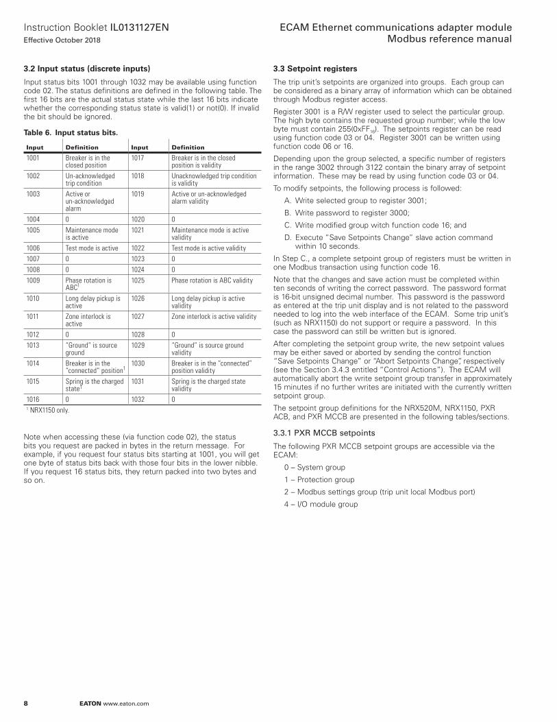
3.2 Input status (discrete inputs)
Input status bits 1001 through 1032 may be available using function code 02 . The status definitions are defined in the following table . The first 16 bits are the actual status state while the last 16 bits indicate whether the corresponding status state is valid(1) or not(0) . If invalid the bit should be ignored .
Table 6. Input status bits.
Input Definition Input Definition
1001 Breaker is in the closed position
1017 Breaker is in the closed position is validity
1002 Un-acknowledged trip condition
1018 Unacknowledged trip condition is validity
1003 Active or un-acknowledged alarm
1019 Active or un-acknowledged alarm validity
1004 0 1020 01005 Maintenance mode
is active1021 Maintenance mode is active
validity1006 Test mode is active 1022 Test mode is active validity1007 0 1023 01008 0 1024 01009 Phase rotation is
ABC11025 Phase rotation is ABC validity
1010 Long delay pickup is active
1026 Long delay pickup is active validity
1011 Zone interlock is active
1027 Zone interlock is active validity
1012 0 1028 01013 “Ground” is source
ground1029 “Ground” is source ground
validity1014 Breaker is in the
“connected” position11030 Breaker is in the “connected”
position validity1015 Spring is the charged
state11031 Spring is the charged state
validity1016 0 1032 01 NRX1150 only.
Note when accessing these (via function code 02), the status bits you request are packed in bytes in the return message . For example, if you request four status bits starting at 1001, you will get one byte of status bits back with those four bits in the lower nibble . If you request 16 status bits, they return packed into two bytes and so on .
3.3 Setpoint registers
The trip unit’s setpoints are organized into groups . Each group can be considered as a binary array of information which can be obtained through Modbus register access .
Register 3001 is a R/W register used to select the particular group . The high byte contains the requested group number; while the low byte must contain 255(0xFF16) . The setpoints register can be read using function code 03 or 04 . Register 3001 can be written using function code 06 or 16 .
Depending upon the group selected, a specific number of registers in the range 3002 through 3122 contain the binary array of setpoint information . These may be read by using function code 03 or 04 .
To modify setpoints, the following process is followed:
A . Write selected group to register 3001;
B . Write password to register 3000;
C . Write modified group witch function code 16; and
D . Execute “Save Setpoints Change” slave action command within 10 seconds .
In Step C ., a complete setpoint group of registers must be written in one Modbus transaction using function code 16 .
Note that the changes and save action must be completed within ten seconds of writing the correct password . The password format is 16-bit unsigned decimal number . This password is the password as entered at the trip unit display and is not related to the password needed to log into the web interface of the ECAM . Some trip unit’s (such as NRX1150) do not support or require a password . In this case the password can still be written but is ignored .
After completing the setpoint group write, the new setpoint values may be either saved or aborted by sending the control function “Save Setpoints Change” or “Abort Setpoints Change”, respectively (see the Section 3 .4 .3 entitled “Control Actions”) . The ECAM will automatically abort the write setpoint group transfer in approximately 15 minutes if no further writes are initiated with the currently written setpoint group .
The setpoint group definitions for the NRX520M, NRX1150, PXR ACB, and PXR MCCB are presented in the following tables/sections .
3.3.1 PXR MCCB setpoints
The following PXR MCCB setpoint groups are accessible via the ECAM:
0 – System group
1 – Protection group
2 – Modbus settings group (trip unit local Modbus port)
4 – I/O module group

9
Instruction Booklet IL0131127ENEffective October 2018
ECAM Ethernet communications adapter module Modbus reference manual
EATON www.eaton.com
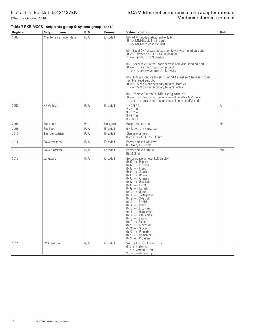
Table 7. PXR MCCB - setpoints group 0: system group.Register Setpoint name R/W Format Value definition Unit
3000 Password W “0000” (factory default). See Section 3.3.3001 Group 0 = system R/W 0x00FF3002 Rating information R Encoded 25 --> 25 A
40 --> 40 A 60 --> 60 A 63 --> 63 A 90 --> 90 A 100 --> 100 A 125 --> 125 A 140 --> 140 A 150 --> 150 A 160 --> 160 A 200 --> 200 A 220 --> 220 A 225 --> 225 A 250 --> 250 A 300 --> 300 A 350 --> 350 A 400 --> 400 A 450 --> 450 A 550 --> 550 A 600 --> 600 A 630 --> 630 A800 --> 800 A 875 --> 875 A 1000 --> 1000 A 1200 --> 1200 A 1250 --> 1250 A 1400 --> 1400 A 1600 --> 1600 A 2000 --> 2000 A 2500 --> 2500 A
A
3003 Break frame R Encoded 00 --> NRX NF 01 --> NRX RF 02 --> Magnum std. 03 --> Magnum narrow 04 --> Magnum double wide 05 --> Magnum double narrow 06 --> MCCB 11 --> NZM2 12 --> NZM3 13 --> NZM4 21 --> PD2 22 --> PD3-A 23 --> PD3-B 24 --> PD4 25 --> PD5 26 --> PD6
3004 Style1 R Encoded 0 = false 1 = true
b0 --> LdSel: with long delay protection b1 --> SdSel: with short delay protection b2 --> InstSel: with Inst protection b3 --> GfSel: with ground fault protection b4 --> ARMSel: with maintenance mode b5 --> OvrideSel: with override protection b6 --> RCDSel: with ground fault RCD b7 --> MotorSel: with motor protection b8 --> NeuSenorSel: with neutral sensor b9 --> ThermalSel: with thermal memory b12 --> VoltSel: with voltage sampling feature b13 --> ExtADCSel: with external AD7779
3005 Style2 R Encoded 0 = false 1 = true
b0 --> ModbusSel: with integrated Modbus b1 --> CAMSel: with CAM RS422 port b2 --> IOModuleSel: with IO module port b3 --> RelaySel: with relay b4 --> ZSISel: with ZSI b5 --> LCDSel: with LCD display feature = 1
10
Instruction Booklet IL0131127ENEffective October 2018
ECAM Ethernet communications adapter module Modbus reference manual
EATON www.eaton.com
Register Setpoint name R/W Format Value definition Unit
3006 Maintenance mode: state R/W Encoded b8 - ARMs mode status, read-only bit. 0 --> MM disabled in trip unit 1 --> MM enabled in trip unit b7 - “Local ON” shows the position MM switch, read-only bit. 0 <--> switch on OFF/REMOTE position 1 <--> switch on ON position b6 - “Local MM Switch” position valid or invalid, read-only bit. 0 <--> rotary switch position is valid 1 <--> rotary switch position is invalid b1 - “MM pin” shows the status of MM signal sent from secondary terminal, read-only bit. 0 <--> MM pin on secondary terminal inactive 1 <--> MM pin on secondary terminal active b0 - “Remote Control” of MM, configurable bit. 0 <--> remote communication channel disables MM mode 1 <--> remote communication channel enables MM mode
3007 ARMs level R/W Encoded 1 = 2.5 * In 2 = 4 * In 3 = 6 * In 4 = 8 * In 5 = 10 * In
A
3008 Frequency R Unsigned Range: 50, 60, 400 Hz3009 Rev Feed R/W Encoded 0 = forward 1 = reverse3010 Sign convention R/W Encoded Sign convention:
0 = IEC, 1 = IEEE, 2 = IEEEalt3011 Power window R/W Encoded Power demand window:
0 = fixed, 1 = sliding3012 Power interval R/W Encoded Power demand interval:
[5…60] minmin
3013 Language R/W Encoded Set language on local LCD display 0x01 --> English 0x02 --> German 0x03 --> French 0x04 --> Spanish 0x05 --> Italian 0x06 --> Chinese 0x07 --> Russian 0x08 --> Dutch 0x09 --> Danish 0x10 --> Greek 0x11 --> Portuguese 0x12 --> Swedish 0x13 --> Finnish 0x14 --> Czech 0x15 --> Estonian 0x16 --> Hungarian 0x17 --> Lithuanian 0x18 --> Latvian 0x19 --> Polish 0x20 --> Slovenian 0x21 --> Slovak 0x22 --> Bulgarian 0x23 --> Romanian 0x24 --> Croatian
3014 LCD_Rotation R/W Encoded Setting LCD display direction. 0 <--> horizontal 1 <--> vertical – left 2 <--> vertical – right
Table 7 PXR MCCB - setpoints group 0: system group (cont.).

11
Instruction Booklet IL0131127ENEffective October 2018
ECAM Ethernet communications adapter module Modbus reference manual
EATON www.eaton.com
Register Setpoint name R/W Format Value definition Unit
301530163017
Relay_Config1Relay_Config2Relay_Config3
R/WR/WR/W
EncodedEncodedEncoded
Relay 1/2/3 function configuration: OFF_RELAY 0x0000TRIP_OVERLOAD_RELAY 0x0001TRIP_NEUTRAL_RELAY 0x0002TRIP_SHORTCIRCUIT_RELAY 0x0003TRIP_SHORTDELAY_RELAY 0x0004TRIP_INST_RELAY 0x0005TRIP_GROUND_RELAY 0x0006TRIP_MM_RELAY 0x0007TRIP_ALL_RELAY 0x0008TRIP_OV_RELAY 0x0009TRIP_UV_RELAY 0x000ATRIP_VUNB_RELAY 0x000BTRIP_IUNB_RELAY 0x000CTRIP_REVPOWER_RELAY 0x000DTRIP_PHASESEQ_RELAY 0x000ETRIP_PHASELOSS_RELAY 0x000FAUX_RELAY 0x0020BELL_RELAY 0x0021MM_ACTIVE_RELAY 0x0022ZSI_ACTIVE_RELAY 0x0023ZSI_INPUT_RELAY 0x0024ZSI_OUTPUT_RELAT 0x0025COMM_OPEN_RBK_RELAY 0x0026COMM_CLOSE_BRK_RELAY 0x0027OUTPUT_1_RELAY 0x0028ALARM_HL_ALARM_RELAY 0x0040ALARM_HL_LOAD_RELAY 0x0041ALARM_HIGHTEMP_RELAY 0x0042ALARM_GROUND_RELAY 0x0043ALARM_THERMAL_RELAY 0x0044ALARM_WATCHDOG_RELAY 0x0045ALARM_LOW_BAT_RELAY 0x0046ALARM_INTERNAL_FAULT_RELAY 0x0047RESERVED 0x0048ALARM_BRK_HEALTH_RELAY 0x0049 ALARM_COMM_FAULT_RELAY 0x004AALARM_ALL_RELAY 0x004BALARM_OV_RELAY 0x004CALARM_UV_RELAY 0x004DALARM_VUNB_RELAY 0x004EALARM_IUNB_RELAY 0x004FALARM_REVPOWER_RELAY 0x0050ALARM_PHASESEQ_RELAY 0x0051ALARM_PHASELOSS_RELAY 0x0052
3018 Pole location - phase A(1) R/W Encoded Pole location - phase A(1)0 - left1 - right
3019 (Future) current demand window
R/W Encoded 0 - fixed 1 - sliding
3020 (Future) current demand window
R/W Unsigned [5…60] step 1 min
3021 Breaker health alarm R/W Unsigned [50…100] step 1 %
Table 7 PXR MCCB - setpoints group 0: system group (cont.).
12
Instruction Booklet IL0131127ENEffective October 2018
ECAM Ethernet communications adapter module Modbus reference manual
EATON www.eaton.com
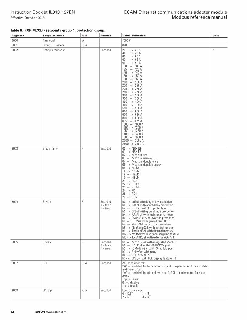
Table 8. PXR MCCB - setpoints group 1: protection group.Register Setpoint name R/W Format Value definition Unit
3000 Password W “0000”3001 Group 0 = system R/W 0x00FF3002 Rating information R Encoded 25 --> 25 A
40 --> 40 A60 --> 60 A63 --> 63 A90 --> 90 A100 --> 100 A125 --> 125 A140 --> 140 A150 --> 150 A160 --> 160 A200 --> 200 A220 --> 220 A225 --> 225 A250 --> 250 A300 --> 300 A350 --> 350 A400 --> 400 A450 --> 450 A550 --> 550 A600 --> 600 A630 --> 630 A800 --> 800 A875 --> 875 A1000 --> 1000 A 1200 --> 1200 A1250 --> 1250 A1400 --> 1400 A1600 --> 1600 A2000 --> 2000 A2500 --> 2500 A
A
3003 Break frame R Encoded 00 --> NRX NF01 --> NRX RF02 --> Magnum std.03 --> Magnum narrow04 --> Magnum double wide05 --> Magnum double narrow06 --> MCCB11 --> NZM212 --> NZM313 --> NZM421 --> PD222 --> PD3-A23 --> PD3-B24 --> PD425 --> PD526 --> PD6
3004 Style 1 R Encoded0 = false1 = true
b0 --> LdSel: with long delay protectionb1 --> SdSel: with short delay protection b2 --> InstSel: with Inst protectionb3 --> GfSel: with ground fault protection b4 --> ARMSel: with maintenance mode b5 --> OvrideSel: with override protection b6 --> RCDSel: with ground fault RCD b7 --> MotorSel: with motor protectionb8 --> NeuSenorSel: with neutral sensor b9 --> ThermalSel: with thermal memory b12 --> VoltSel: with voltage sampling feature b13 --> ExtADCSel: with external AD7779
3005 Style 2 R Encoded0 = false1 = true
b0 --> ModbusSel: with integrated Modbusb1 --> CAMSel: with CAM RS422 portb2 --> IOModuleSel: with IO module portb3 --> RelaySel: with relayb4 --> ZSISel: with ZSIb5 - -> LCDSel: with LCD display feature = 1
3007 ZSI R/W Encoded ZSI, zone interlock*When enabled, for trip unit with G, ZSI is implemented for short delay and ground fault.*When enabled, for trip unit without G, ZSI is implemented for short delay.Trip unit side:0 <--> disable1 <--> enable
3008 LD_Slp R/W Encoded Long delay slope:0 = I0.5T 1 = IT2 = I2T 3 = I4T
13
Instruction Booklet IL0131127ENEffective October 2018
ECAM Ethernet communications adapter module Modbus reference manual
EATON www.eaton.com
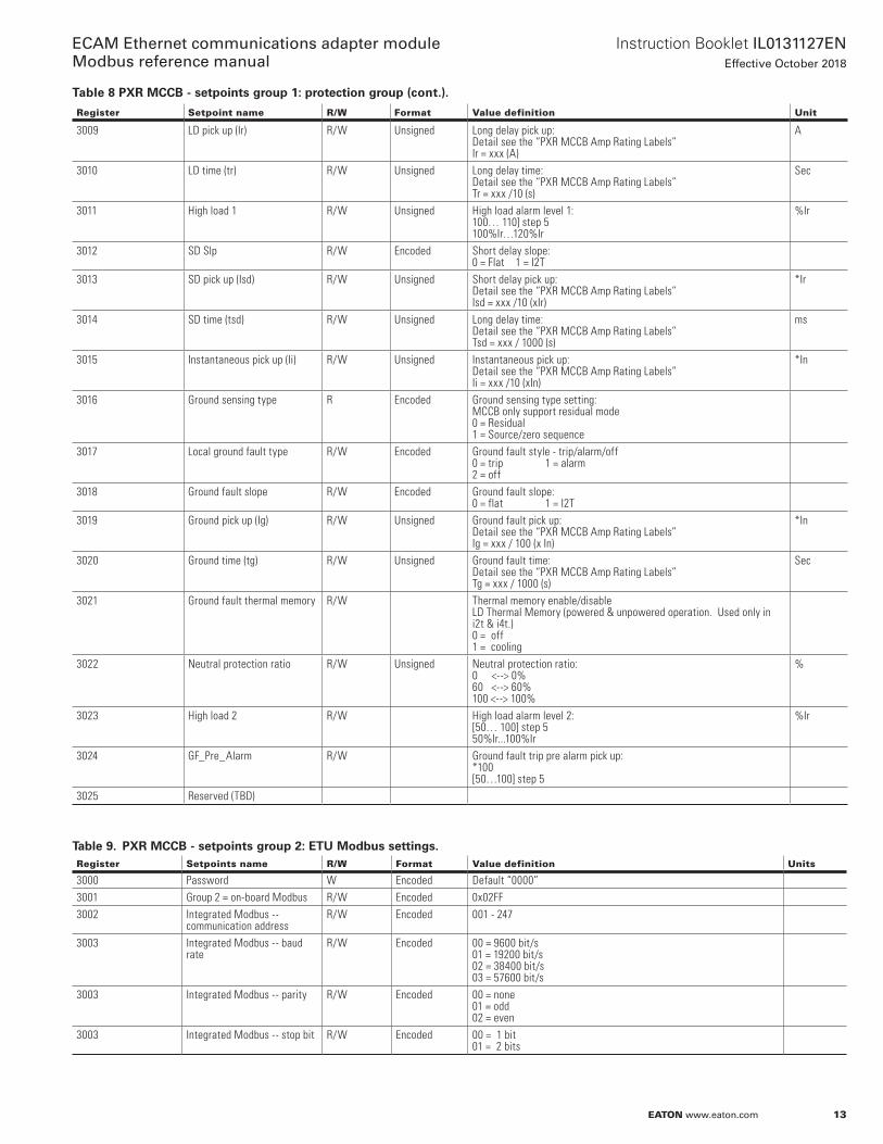
Register Setpoint name R/W Format Value definition Unit
3009 LD pick up (Ir) R/W Unsigned Long delay pick up:Detail see the “PXR MCCB Amp Rating Labels”Ir = xxx (A)
A
3010 LD time (tr) R/W Unsigned Long delay time:Detail see the “PXR MCCB Amp Rating Labels”Tr = xxx /10 (s)
Sec
3011 High load 1 R/W Unsigned High load alarm level 1:100… 110] step 5 100%Ir…120%Ir
%Ir
3012 SD Slp R/W Encoded Short delay slope: 0 = Flat 1 = I2T
3013 SD pick up (Isd) R/W Unsigned Short delay pick up:Detail see the “PXR MCCB Amp Rating Labels”Isd = xxx /10 (xIr)
*Ir
3014 SD time (tsd) R/W Unsigned Long delay time:Detail see the “PXR MCCB Amp Rating Labels”Tsd = xxx / 1000 (s)
ms
3015 Instantaneous pick up (Ii) R/W Unsigned Instantaneous pick up:Detail see the “PXR MCCB Amp Rating Labels”Ii = xxx /10 (xIn)
*In
3016 Ground sensing type R Encoded Ground sensing type setting:MCCB only support residual mode0 = Residual1 = Source/zero sequence
3017 Local ground fault type R/W Encoded Ground fault style - trip/alarm/off0 = trip 1 = alarm2 = off
3018 Ground fault slope R/W Encoded Ground fault slope:0 = flat 1 = I2T
3019 Ground pick up (Ig) R/W Unsigned Ground fault pick up:Detail see the “PXR MCCB Amp Rating Labels”Ig = xxx / 100 (x In)
*In
3020 Ground time (tg) R/W Unsigned Ground fault time:Detail see the “PXR MCCB Amp Rating Labels”Tg = xxx / 1000 (s)
Sec
3021 Ground fault thermal memory R/W Thermal memory enable/disableLD Thermal Memory (powered & unpowered operation. Used only in i2t & i4t.)0 = off1 = cooling
3022 Neutral protection ratio R/W Unsigned Neutral protection ratio:0 <--> 0%60 <--> 60%100 <--> 100%
%
3023 High load 2 R/W High load alarm level 2:[50… 100] step 550%Ir...100%Ir
%Ir
3024 GF_Pre_Alarm R/W Ground fault trip pre alarm pick up: *100[50…100] step 5
3025 Reserved (TBD)
Table 9. PXR MCCB - setpoints group 2: ETU Modbus settings.Register Setpoints name R/W Format Value definition Units
3000 Password W Encoded Default “0000”3001 Group 2 = on-board Modbus R/W Encoded 0x02FF3002 Integrated Modbus --
communication address R/W Encoded 001 - 247
3003 Integrated Modbus -- baud rate
R/W Encoded 00 = 9600 bit/s01 = 19200 bit/s02 = 38400 bit/s03 = 57600 bit/s
3003 Integrated Modbus -- parity R/W Encoded 00 = none01 = odd02 = even
3003 Integrated Modbus -- stop bit R/W Encoded 00 = 1 bit01 = 2 bits
Table 8 PXR MCCB - setpoints group 1: protection group (cont.).

14
Instruction Booklet IL0131127ENEffective October 2018
ECAM Ethernet communications adapter module Modbus reference manual
EATON www.eaton.com
Table 10. PXR MCCB - setpoints group 4: I/O module group.Register Setpoints name R/W Format Value definition
3000 Password W Encoded Default “0000”3001 I/O module Cfg R/W Encoded 0x04FF3002 Validity flags 0….15 R/W Encoded For each bit:
0: corresponding parameter inactive1: corresponding parameter activee.g. Bit 8 = 1 ==> parameter 8 = active
3003 Validity flags 16….31 R/W Encoded For each bit: 0: corresponding parameter inactive1: corresponding parameter activee.g. Bit 8 = 1 ==> parameter 8 = active
3004 0: digital output 0 R/W Encoded3005 1: digital output 1 R/W Encoded3006 2: digital output 2 R/W Encoded3007 3: digital output 3 R/W Encoded3008 4: S0 channel 0 type R/W 0: ouput disabled
1: sends pulses based on active energy2: sends pulses based on reactive energy3: sends pulses based on apparent energy
3009 5: S0 channel 0 scale R/W 0: sends a pulse every 1 W1: sends a pulse every 10 W2: sends a pulse every 100 W3: sends a pulse every 1000 W
3010 6: S0 channel 0 pulse R/W pulse duration x *10 msrange: 1…50 ==> 10…500 ms
3011 7: S0 channel 1 type R/W 0: output disabled1: sends pulses based on active energy2: sends pulses based on reactive energy3: sends pulses based on apparent energy
3012 8: S0 channel 1 scale R/W 0: sends a pulse every 1 W1: sends a pulse every 10 W2: sends a pulse every 100 W3: sends a pulse every 1000 W
3013 9: S0 channel 1 pulse R/W Pulse duration x *10 mRange: 1…50 ==> 10…500 ms s
3014 10: Modbus address R/W Modbus ID (= device address)Permitted range: 1…255
3015 11: Modbus baud rate R/W 0: 9600 bit/1: 19200 bit/s2: 38400 bit/s3: 57600 bit/s s4:115200 bit/s ( TBD, not used in code)
3016 12: Modbus parity R/W Modbus parity / Stop bits:0: no parity / 2 stop bits1: even parity, 1 stop bit2: odd parity, 1 stop bit
3017 Reserved 13018 Reserved 23019 Reserved 33020 Reserved 43021 Reserved 53022 Reserved 63023 Reserved 73024 Reserved 83025 Reserved 93026 Reserved 10
15
Instruction Booklet IL0131127ENEffective October 2018
ECAM Ethernet communications adapter module Modbus reference manual
EATON www.eaton.com
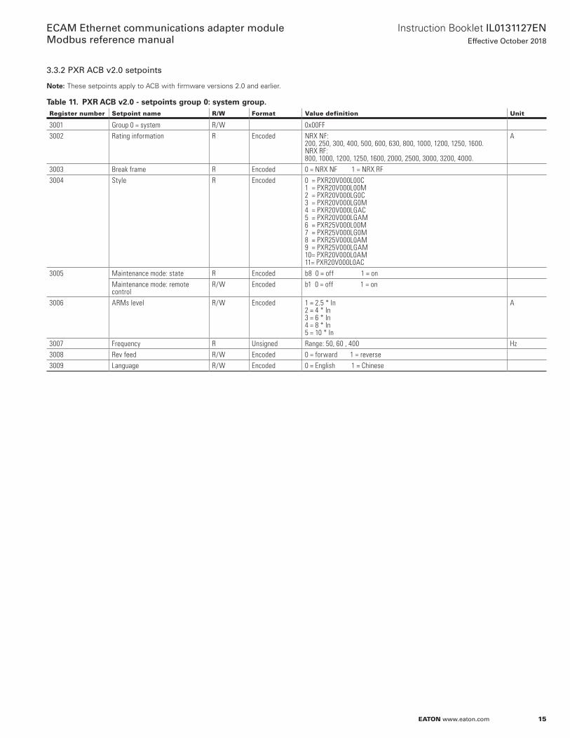
3.3.2 PXR ACB v2.0 setpoints
ote:N These setpoints apply to ACB with firmware versions 2 .0 and earlier .
Table 11. PXR ACB v2.0 - setpoints group 0: system group.Register number Setpoint name R/W Format Value definition Unit
3001 Group 0 = system R/W 0x00FF3002 Rating information R Encoded NRX NF:
200, 250, 300, 400, 500, 600, 630, 800, 1000, 1200, 1250, 1600.NRX RF: 800, 1000, 1200, 1250, 1600, 2000, 2500, 3000, 3200, 4000.
A
3003 Break frame R Encoded 0 = NRX NF 1 = NRX RF3004 Style R Encoded 0 = PXR20V000L00C
1 = PXR20V000L00M2 = PXR20V000LG0C3 = PXR20V000LG0M4 = PXR20V000LGAC5 = PXR20V000LGAM6 = PXR25V000L00M7 = PXR25V000LG0M8 = PXR25V000L0AM9 = PXR25V000LGAM10= PXR20V000L0AM11= PXR20V000L0AC
3005 Maintenance mode: state R Encoded b8 0 = off 1 = onMaintenance mode: remote control
R/W Encoded b1 0 = off 1 = on
3006 ARMs level R/W Encoded 1 = 2.5 * In2 = 4 * In3 = 6 * In4 = 8 * In5 = 10 * In
A
3007 Frequency R Unsigned Range: 50, 60 , 400 Hz3008 Rev feed R/W Encoded 0 = forward 1 = reverse3009 Language R/W Encoded 0 = English 1 = Chinese
16
Instruction Booklet IL0131127ENEffective October 2018
ECAM Ethernet communications adapter module Modbus reference manual
EATON www.eaton.com
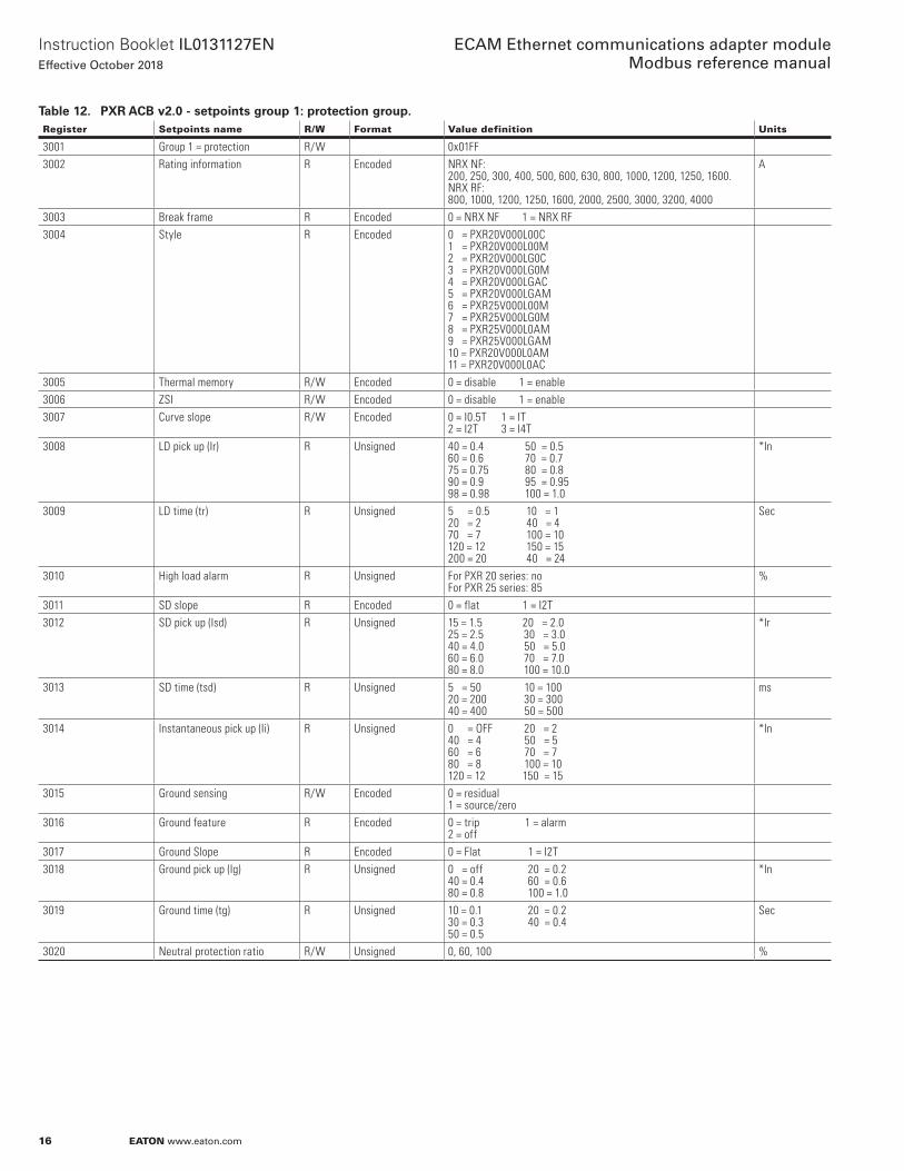
Table 12. PXR ACB v2.0 - setpoints group 1: protection group.Register Setpoints name R/W Format Value definition Units
3001 Group 1 = protection R/W 0x01FF3002 Rating information R Encoded NRX NF:
200, 250, 300, 400, 500, 600, 630, 800, 1000, 1200, 1250, 1600.NRX RF: 800, 1000, 1200, 1250, 1600, 2000, 2500, 3000, 3200, 4000
A
3003 Break frame R Encoded 0 = NRX NF 1 = NRX RF3004 Style R Encoded 0 = PXR20V000L00C
1 = PXR20V000L00M2 = PXR20V000LG0C3 = PXR20V000LG0M4 = PXR20V000LGAC5 = PXR20V000LGAM6 = PXR25V000L00M7 = PXR25V000LG0M8 = PXR25V000L0AM9 = PXR25V000LGAM10 = PXR20V000L0AM11 = PXR20V000L0AC
3005 Thermal memory R/W Encoded 0 = disable 1 = enable3006 ZSI R/W Encoded 0 = disable 1 = enable3007 Curve slope R/W Encoded 0 = I0.5T 1 = IT
2 = I2T 3 = I4T3008 LD pick up (Ir) R Unsigned 40 = 0.4 50 = 0.5
60 = 0.6 70 = 0.7 75 = 0.75 80 = 0.8 90 = 0.9 95 = 0.95 98 = 0.98 100 = 1.0
*In
3009 LD time (tr) R Unsigned 5 = 0.5 10 = 1 20 = 2 40 = 470 = 7 100 = 10 120 = 12 150 = 15200 = 20 40 = 24
Sec
3010 High load alarm R Unsigned For PXR 20 series: noFor PXR 25 series: 85
%
3011 SD slope R Encoded 0 = flat 1 = I2T3012 SD pick up (Isd) R Unsigned 15 = 1.5 20 = 2.0
25 = 2.5 30 = 3.040 = 4.0 50 = 5.0 60 = 6.0 70 = 7.0 80 = 8.0 100 = 10.0
*Ir
3013 SD time (tsd) R Unsigned 5 = 50 10 = 100 20 = 200 30 = 300 40 = 400 50 = 500
ms
3014 Instantaneous pick up (Ii) R Unsigned 0 = OFF 20 = 2 40 = 4 50 = 5 60 = 6 70 = 7 80 = 8 100 = 10 120 = 12 150 = 15
*In
3015 Ground sensing R/W Encoded 0 = residual 1 = source/zero
3016 Ground feature R Encoded 0 = trip 1 = alarm 2 = off
3017 Ground Slope R Encoded 0 = Flat 1 = I2T3018 Ground pick up (Ig) R Unsigned 0 = off 20 = 0.2
40 = 0.4 60 = 0.6 80 = 0.8 100 = 1.0
*In
3019 Ground time (tg) R Unsigned 10 = 0.1 20 = 0.2 30 = 0.3 40 = 0.4 50 = 0.5
Sec
3020 Neutral protection ratio R/W Unsigned 0, 60, 100 %
17
Instruction Booklet IL0131127ENEffective October 2018
ECAM Ethernet communications adapter module Modbus reference manual
EATON www.eaton.com
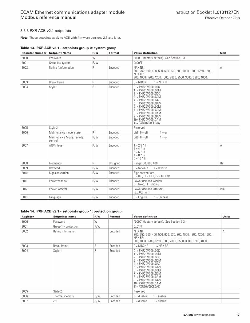
3.3.3 PXR ACB v2.1 setpoints
ote:N These setpoints apply to ACB with firmware versions 2 .1 and later .
Table 13. PXR ACB v2.1 - setpoints group 0: system group.Register Number Setpoint Name R/W Format Value Definition Unit
3000 Password W “0000” (factory default). See Section 3.3.3001 Group 0 = system R/W 0x00FF3002 Rating I\information R Encoded NRX NF:
200, 250, 300, 400, 500, 600, 630, 800, 1000, 1200, 1250, 1600.NRX RF: 800, 1000, 1200, 1250, 1600, 2000, 2500, 3000, 3200, 4000.
A
3003 Break frame R Encoded 0 = NRX NF 1 = NRX RF3004 Style 1 R Encoded 0 = PXR20V000L00C
1 = PXR20V000L00M2 = PXR20V000LG0C3 = PXR20V000LG0M4 = PXR20V000LGAC5 = PXR20V000LGAM6 = PXR25V000L00M7 = PXR25V000LG0M8 = PXR25V000L0AM9 = PXR25V000LGAM10= PXR20V000L0AM11= PXR20V000L0AC
3005 Style 2 Reserved3006 Maintenance mode: state R Encoded bit8 0 = off 1 = on
Maintenance Mode: remote control
R/W Encoded bit0 0 = off 1 = on
3007 ARMs level R/W Encoded 1 = 2.5 * In2 = 4 * In3 = 6 * In4 = 8 * In5 = 10 * In
A
3008 Frequency R Unsigned Range: 50, 60 , 400 Hz3009 Rev feed R/W Encoded 0 = forward 1 = reverse3010 Sign convention R/W Encoded Sign convention:
0 = IEC, 1 = IEEE, 2 = IEEEalt3011 Power window R/W Encoded Power demand window
0 = fixed, 1 = sliding:3012 Power interval R/W Encoded Power demand interval:
[5…60] minmin
3013 Language R/W Encoded 0 = English 1 = Chinese
Table 14. PXR ACB v2.1 - setpoints group 1: protection group.Register Setpoints name R/W Format Value definition Units
3000 Password W “0000” (factory default). See Section 3.3.3001 Group 1 = protection R/W 0x01FF3002 Rating information R Encoded NRX NF:
200, 250, 300, 400, 500, 600, 630, 800, 1000, 1200, 1250, 1600.NRX RF: 800, 1000, 1200, 1250, 1600, 2000, 2500, 3000, 3200, 4000.
A
3003 Break frame R Encoded 0 = NRX NF 1 = NRX RF3004 Style 1 R Encoded 0 = PXR20V000L00C
1 = PXR20V000L00M2 = PXR20V000LG0C3 = PXR20V000LG0M4 = PXR20V000LGAC5 = PXR20V000LGAM6 = PXR25V000L00M7 = PXR25V000LG0M8 = PXR25V000L0AM9 = PXR25V000LGAM10= PXR20V000L0AM11= PXR20V000L0AC
3005 Style 2 Reserved3006 Thermal memory R/W Encoded 0 = disable 1 = enable3007 ZSI R/W Encoded 0 = disable 1 = enable

18
Instruction Booklet IL0131127ENEffective October 2018
ECAM Ethernet communications adapter module Modbus reference manual
EATON www.eaton.com
Register Setpoints name R/W Format Value definition Units
3008 Curve slope R/W Encoded 0 = I0.5T 1 = IT 2 = I2T 3 = I4T
3009 LD pick up (Ir) R Unsigned 40 = 0.4 50 = 0.5 60 = 0.6 70 = 0.7 75 = 0.75 80 = 0.8 90 = 0.9 95 = 0.95 98 = 0.98 100 = 1.0
*In
3010 LD time (tr) R Unsigned 5 = 0.5 10 = 1 20 = 2 40 = 470 = 7 100 = 10 120 = 12 150 = 15200 = 20 240 = 24
Sec
3011 High load alarm R Unsigned For PXR 20 series: NoFor PXR 25 series: 85
%
3012 SD slope R Encoded 0 = Flat 1 = I2T3013 SD pick up (Isd) R Unsigned 15 = 1.5 20 = 2.0
25 = 2.5 30 = 3.040 = 4.0 50 = 5.0 60 = 6.0 70 = 7.0 80 = 8.0 100 = 10.0
*Ir
3014 SD time (tsd) R Unsigned 5 = 50 10 = 100 20 = 200 30 = 300 40 = 400 50 = 500
ms
3015 Instantaneous pick up (Ii) R Unsigned 0 = off 20 = 2 40 = 4 50 = 5 60 = 6 70 = 7 80 = 8 100 = 10 120 = 12 150 = 15
*In
3016 Ground sensing R/W Encoded 0 = residual 1 = source/zero
3017 Ground fault type R Encoded 0 = trip 1 = alarm 2 = off
3018 Ground slope R Encoded 0 = flat 1 = I2T3019 Ground pick up (Ig) R Unsigned 0 = off 20 = 0.2
40 = 0.4 60 = 0.6 80 = 0.8 100 = 1.0
*In
3020 Ground time (tg) R Unsigned 10 = 0.1 20 = 0.2 30 = 0.3 40 = 0.4 50 = 0.5
Sec
3021 Ground fault thermal memory R/W Thermal memory enable/disable.LD thermal memory (powered & unpowered operation. Used only in i2t & i4t)0 = off1 = cooling
3022 Neutral protection ratio R/W Unsigned 0, 60, 100 %3023 High load 2 R/W High load alarm level 2:
[50… 100] step 550%Ir...100%Ir
%Ir
3024 GF_Pre_Alarm R/W Ground fault trip pre alarm pick up: *100[50…100] step 5
3025 Reserved (TBD)
Table 14. PXR ACB v2.1 - setpoints group 1: protection group (cont.).
19
Instruction Booklet IL0131127ENEffective October 2018
ECAM Ethernet communications adapter module Modbus reference manual
EATON www.eaton.com
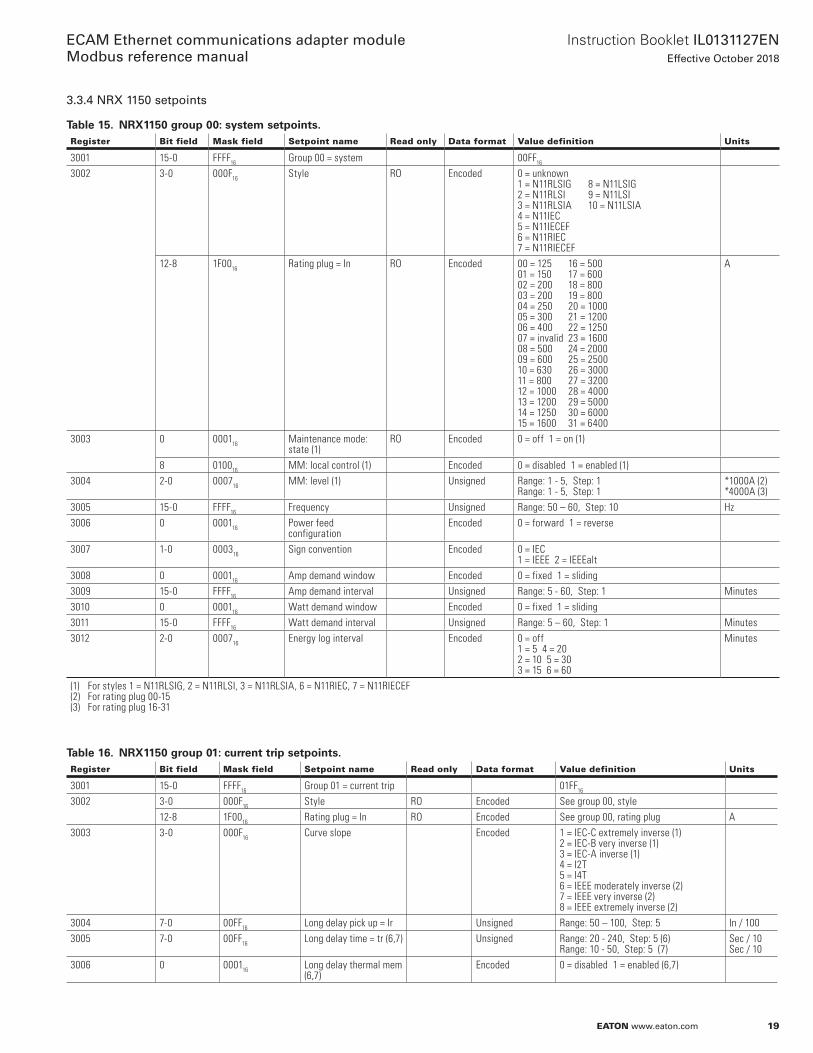
3.3.4 NRX 1150 setpoints
Table 15. NRX1150 group 00: system setpoints.Register Bit field Mask field Setpoint name Read only Data format Value definition Units
3001 15-0 FFFF16 Group 00 = system 00FF16
3002 3-0 000F16 Style RO Encoded 0 = unknown 1 = N11RLSIG 8 = N11LSIG2 = N11RLSI 9 = N11LSI3 = N11RLSIA 10 = N11LSIA4 = N11IEC5 = N11IECEF6 = N11RIEC7 = N11RIECEF
12-8 1F0016 Rating plug = In RO Encoded 00 = 125 16 = 50001 = 150 17 = 60002 = 200 18 = 80003 = 200 19 = 80004 = 250 20 = 100005 = 300 21 = 120006 = 400 22 = 125007 = invalid 23 = 160008 = 500 24 = 200009 = 600 25 = 250010 = 630 26 = 300011 = 800 27 = 320012 = 1000 28 = 400013 = 1200 29 = 500014 = 1250 30 = 600015 = 1600 31 = 6400
A
3003 0 000116 Maintenance mode: state (1)
RO Encoded 0 = off 1 = on (1)
8 010016 MM: local control (1) Encoded 0 = disabled 1 = enabled (1)3004 2-0 000716 MM: level (1) Unsigned Range: 1 - 5, Step: 1
Range: 1 - 5, Step: 1*1000A (2)*4000A (3)
3005 15-0 FFFF16 Frequency Unsigned Range: 50 – 60, Step: 10 Hz3006 0 000116 Power feed
configurationEncoded 0 = forward 1 = reverse
3007 1-0 000316 Sign convention Encoded 0 = IEC1 = IEEE 2 = IEEEalt
3008 0 000116 Amp demand window Encoded 0 = fixed 1 = sliding3009 15-0 FFFF16 Amp demand interval Unsigned Range: 5 - 60, Step: 1 Minutes3010 0 000116 Watt demand window Encoded 0 = fixed 1 = sliding3011 15-0 FFFF16 Watt demand interval Unsigned Range: 5 – 60, Step: 1 Minutes3012 2-0 000716 Energy log interval Encoded 0 = off
1 = 5 4 = 202 = 10 5 = 303 = 15 6 = 60
Minutes
(1) For styles 1 = N11RLSIG, 2 = N11RLSI, 3 = N11RLSIA, 6 = N11RIEC, 7 = N11RIECEF(2) For rating plug 00-15(3) For rating plug 16-31
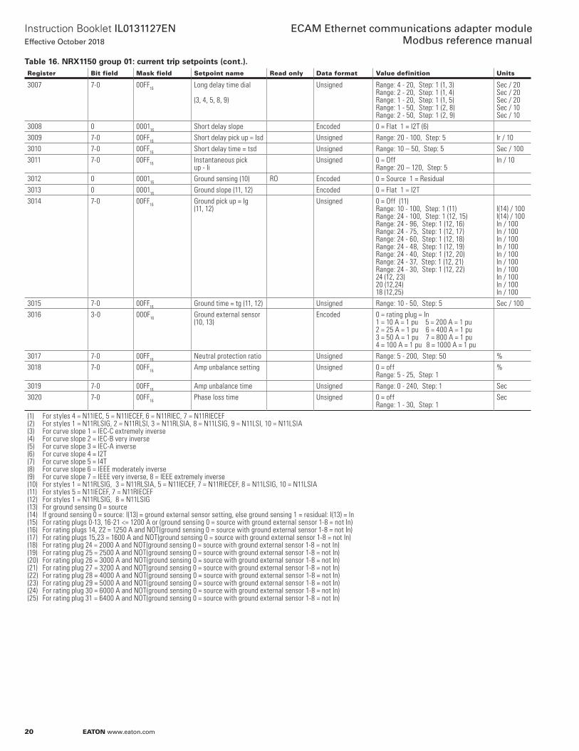
Table 16. NRX1150 group 01: current trip setpoints.Register Bit field Mask field Setpoint name Read only Data format Value definition Units
3001 15-0 FFFF16 Group 01 = current trip 01FF16
3002 3-0 000F16 Style RO Encoded See group 00, style12-8 1F0016 Rating plug = In RO Encoded See group 00, rating plug A
3003 3-0 000F16 Curve slope Encoded 1 = IEC-C extremely inverse (1)2 = IEC-B very inverse (1)3 = IEC-A inverse (1)4 = I2T 5 = I4T 6 = IEEE moderately inverse (2)7 = IEEE very inverse (2)8 = IEEE extremely inverse (2)
3004 7-0 00FF16 Long delay pick up = Ir Unsigned Range: 50 – 100, Step: 5 In / 1003005 7-0 00FF16 Long delay time = tr (6,7) Unsigned Range: 20 - 240, Step: 5 (6)
Range: 10 - 50, Step: 5 (7)Sec / 10Sec / 10
3006 0 000116 Long delay thermal mem (6,7)
Encoded 0 = disabled 1 = enabled (6,7)
20
Instruction Booklet IL0131127ENEffective October 2018
ECAM Ethernet communications adapter module Modbus reference manual
EATON www.eaton.com
Register Bit field Mask field Setpoint name Read only Data format Value definition Units
3007 7-0 00FF16 Long delay time dial
(3, 4, 5, 8, 9)
Unsigned Range: 4 - 20, Step: 1 (1, 3)Range: 2 - 20, Step: 1 (1, 4)Range: 1 - 20, Step: 1 (1, 5)Range: 1 - 50, Step: 1 (2, 8)Range: 2 - 50, Step: 1 (2, 9)
Sec / 20Sec / 20Sec / 20Sec / 10Sec / 10
3008 0 000116 Short delay slope Encoded 0 = Flat 1 = I2T (6)3009 7-0 00FF16 Short delay pick up = Isd Unsigned Range: 20 - 100, Step: 5 Ir / 103010 7-0 00FF16 Short delay time = tsd Unsigned Range: 10 – 50, Step: 5 Sec / 1003011 7-0 00FF16 Instantaneous pick
up - IiUnsigned 0 = Off
Range: 20 – 120, Step: 5In / 10
3012 0 000116 Ground sensing (10) RO Encoded 0 = Source 1 = Residual3013 0 000116 Ground slope (11, 12) Encoded 0 = Flat 1 = I2T3014 7-0 00FF16 Ground pick up = Ig
(11, 12)Unsigned 0 = Off (11)
Range: 10 - 100, Step: 1 (11)Range: 24 - 100, Step: 1 (12, 15)Range: 24 - 96, Step: 1 (12, 16)Range: 24 - 75, Step: 1 (12, 17)Range: 24 - 60, Step: 1 (12, 18)Range: 24 - 48, Step: 1 (12, 19)Range: 24 - 40, Step: 1 (12, 20)Range: 24 - 37, Step: 1 (12, 21)Range: 24 - 30, Step: 1 (12, 22)24 (12, 23)20 (12,24)18 (12,25)
I(14) / 100I(14) / 100In / 100In / 100In / 100In / 100In / 100In / 100In / 100In / 100In / 100In / 100
3015 7-0 00FF16 Ground time = tg (11, 12) Unsigned Range: 10 - 50, Step: 5 Sec / 1003016 3-0 000F16 Ground external sensor
(10, 13)Encoded 0 = rating plug = In
1 = 10 A = 1 pu 5 = 200 A = 1 pu2 = 25 A = 1 pu 6 = 400 A = 1 pu3 = 50 A = 1 pu 7 = 800 A = 1 pu4 = 100 A = 1 pu 8 = 1000 A = 1 pu
3017 7-0 00FF16 Neutral protection ratio Unsigned Range: 5 - 200, Step: 50 %3018 7-0 00FF16 Amp unbalance setting Unsigned 0 = off
Range: 5 - 25, Step: 1%
3019 7-0 00FF16 Amp unbalance time Unsigned Range: 0 - 240, Step: 1 Sec3020 7-0 00FF16 Phase loss time Unsigned 0 = off
Range: 1 - 30, Step: 1Sec
(1) For styles 4 = N11IEC, 5 = N11IECEF, 6 = N11RIEC, 7 = N11RIECEF(2) For styles 1 = N11RLSIG, 2 = N11RLSI, 3 = N11RLSIA, 8 = N11LSIG, 9 = N11LSI, 10 = N11LSIA(3) For curve slope 1 = IEC-C extremely inverse(4) For curve slope 2 = IEC-B very inverse(5) For curve slope 3 = IEC-A inverse(6) For curve slope 4 = I2T(7) For curve slope 5 = I4T(8) For curve slope 6 = IEEE moderately inverse(9) For curve slope 7 = IEEE very inverse, 8 = IEEE extremely inverse(10) For styles 1 = N11RLSIG, 3 = N11RLSIA, 5 = N11IECEF, 7 = N11RIECEF, 8 = N11LSIG, 10 = N11LSIA(11) For styles 5 = N11IECEF, 7 = N11RIECEF(12) For styles 1 = N11RLSIG, 8 = N11LSIG(13) For ground sensing 0 = source(14) If ground sensing 0 = source: I(13) = ground external sensor setting, else ground sensing 1 = residual: I(13) = In(15) For rating plugs 0-13, 16-21 <= 1200 A or (ground sensing 0 = source with ground external sensor 1-8 = not In)(16) For rating plugs 14, 22 = 1250 A and NOT(ground sensing 0 = source with ground external sensor 1-8 = not In)(17) For rating plugs 15,23 = 1600 A and NOT(ground sensing 0 = source with ground external sensor 1-8 = not In)(18) For rating plug 24 = 2000 A and NOT(ground sensing 0 = source with ground external sensor 1-8 = not In)(19) For rating plug 25 = 2500 A and NOT(ground sensing 0 = source with ground external sensor 1-8 = not In)(20) For rating plug 26 = 3000 A and NOT(ground sensing 0 = source with ground external sensor 1-8 = not In)(21) For rating plug 27 = 3200 A and NOT(ground sensing 0 = source with ground external sensor 1-8 = not In)(22) For rating plug 28 = 4000 A and NOT(ground sensing 0 = source with ground external sensor 1-8 = not In)(23) For rating plug 29 = 5000 A and NOT(ground sensing 0 = source with ground external sensor 1-8 = not In)(24) For rating plug 30 = 6000 A and NOT(ground sensing 0 = source with ground external sensor 1-8 = not In)(25) For rating plug 31 = 6400 A and NOT(ground sensing 0 = source with ground external sensor 1-8 = not In)
Table 16. NRX1150 group 01: current trip setpoints (cont.).
21
Instruction Booklet IL0131127ENEffective October 2018
ECAM Ethernet communications adapter module Modbus reference manual
EATON www.eaton.com
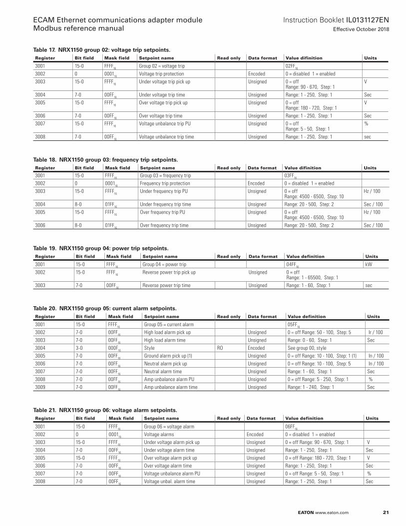
Table 17. NRX1150 group 02: voltage trip setpoints.Register Bit field Mask field Setpoint name Read only Data format Value difinition Units
3001 15-0 FFFF16 Group 02 = voltage trip 02FF16
3002 0 000116 Voltage trip protection Encoded 0 = disabled 1 = enabled3003 15-0 FFFF16 Under voltage trip pick up Unsigned 0 = off
Range: 90 - 670, Step: 1V
3004 7-0 00FF16 Under voltage trip time Unsigned Range: 1 - 250, Step: 1 Sec3005 15-0 FFFF16 Over voltage trip pick up Unsigned 0 = off
Range: 180 - 720, Step: 1V
3006 7-0 00FF16 Over voltage trip time Unsigned Range: 1 - 250, Step: 1 Sec3007 15-0 FFFF16 Voltage unbalance trip PU Unsigned 0 = off
Range: 5 - 50, Step: 1%
3008 7-0 00FF16 Voltage unbalance trip time Unsigned Range: 1 - 250, Step: 1 sec
Table 18. NRX1150 group 03: frequency trip setpoints.Register Bit field Mask field Setpoint name Read only Data format Value difinition Units
3001 15-0 FFFF16 Group 03 = frequency trip 03FF16
3002 0 000116 Frequency trip protection Encoded 0 = disabled 1 = enabled3003 15-0 FFFF16 Under frequency trip PU Unsigned 0 = off
Range: 4500 - 6500, Step: 10Hz / 100
3004 8-0 01FF16 Under frequency trip time Unsigned Range: 20 - 500, Step: 2 Sec / 1003005 15-0 FFFF16 Over frequency trip PU Unsigned 0 = off
Range: 4500 - 6500, Step: 10Hz / 100
3006 8-0 01FF16 Over frequency trip time Unsigned Range: 20 - 500, Step: 2 Sec / 100
Table 19. NRX1150 group 04: power trip setpoints.Register Bit field Mask field Setpoint name Read only Data format Value definition Units
3001 15-0 FFFF16 Group 04 = power trip 04FF16 kW3002 15-0 FFFF16 Reverse power trip pick up Unsigned 0 = off
Range: 1 - 65500, Step: 13003 7-0 00FF16 Reverse power trip time Unsigned Range: 1 - 60, Step: 1 sec
Table 20. NRX1150 group 05: current alarm setpoints.Register Bit field Mask field Setpoint name Read only Data format Value definition Units
3001 15-0 FFFF16 Group 05 = current alarm 05FF16
3002 7-0 00FF16 High load alarm pick up Unsigned 0 = off Range: 50 - 100, Step: 5 Ir / 1003003 7-0 00FF16 High load alarm time Unsigned Range: 0 - 60, Step: 1 Sec3004 3-0 000F16 Style RO Encoded See group 00, style3005 7-0 00FF16 Ground alarm pick up (1) Unsigned 0 = off Range: 10 - 100, Step: 1 (1) In / 1003006 7-0 00FF16 Neutral alarm pick up Unsigned 0 = off Range: 10 - 100, Step: 5 In / 1003007 7-0 00FF16 Neutral alarm time Unsigned Range: 1 - 60, Step: 1 Sec3008 7-0 00FF16 Amp unbalance alarm PU Unsigned 0 = off Range: 5 - 250, Step: 1 %3009 7-0 00FF16 Amp unbalance alarm time Unsigned Range: 1 - 240, Step: 1 Sec
Table 21. NRX1150 group 06: voltage alarm setpoints.Register Bit field Mask field Setpoint name Read only Data format Value definition Units
3001 15-0 FFFF16 Group 06 = voltage alarm 06FF16 3002 0 000116 Voltage alarms Encoded 0 = disabled 1 = enabled3003 15-0 FFFF16 Under voltage alarm pick up Unsigned 0 = off Range: 90 - 670, Step: 1 V3004 7-0 00FF16 Under voltage alarm time Unsigned Range: 1 - 250, Step: 1 Sec3005 15-0 FFFF16 Over voltage alarm pick up Unsigned 0 = off Range: 180 - 720, Step: 1 V3006 7-0 00FF16 Over voltage alarm time Unsigned Range: 1 - 250, Step: 1 Sec3007 7-0 00FF16 Voltage unbalance alarm PU Unsigned 0 = off Range: 5 - 50, Step: 1 %3008 7-0 00FF16 Voltage unbal. alarm time Unsigned Range: 1 - 250, Step: 1 Sec

22
Instruction Booklet IL0131127ENEffective October 2018
ECAM Ethernet communications adapter module Modbus reference manual
EATON www.eaton.com
Table 22. NRX1150 group 07: frequency alarm setpoints.Register Bit field Mask field Setpoint name Read only Data format Value definition Units
3001 15-0 FFFF16 Group 07 = frequency alarm 07FF16
3002 0 000116 Frequency trip protection Encoded 0 = disabled 1 = enabled3003 15-0 FFFF16 Under frequency trip PU Unsigned 0 = off
Range: 4500 - 6500, Step: 10 Hz / 100
3004 15-0 FFFF16 Under frequency trip time Unsigned Range: 20 - 500, Step: 2 Sec / 1003005 15-0 FFFF16 Over frequency trip PU Unsigned 0 = off
Range: 4500 - 6500, Step: 10 Hz / 100
3006 15-0 FFFF16 Over frequency trip time Unsigned Range: 20 - 500, Step: 2 Sec / 100
Table 23. NRX1150 group 08: power alarms setpoints.Register Bit field Mask field Setpoint name Read only Data format Value definition Units
3001 15-0 FFFF16 Group 08 = power alarms 08FF16
3002 0 000116 Power alarms Encoded 0 = disabled 1 = enabled3003 15-0 FFFF16 Watt demand alarm pick up Unsigned 0 = off
Range: 1 - 65500, Step: 1 kW
3004 7-0 00FF16 Watt demand alarm time Unsigned Range: 1 - 60, Step: 1 Sec3005 15-0 FFFF16 VA demand alarm pick up Unsigned 0 = off
Range: 1 - 65500, Step: 1 kVA
3006 7-0 00FF16 VA demand alarm time Unsigned Range: 1 - 60, Step: 1 Sec 3007 15-0 FFFF16 Reverse power alarm pick up Unsigned 0 = 0ff
Range: 1 - 65500, Step: 1kW
3008 7-0 00FF16 Reverse power alarm time Unsigned Range: 1 - 60, Step: 1 Sec 3009 15-0 FFFF16 Low PF alarm pick up Unsigned 0 = 0ff
Range: 50 - 95, Step: 5 / 100
3010 7-0 00FF16 Low PF alarm time Unsigned Range: 1 - 60, Step: 1 Sec
Table 24. NRX1150 group 09: other alarm setpoints.Register Bit field Mask field Setpoint name Read only Data format Value definition Units
3001 15-0 FFFF16 Group 09 = other alarm 09FF16
3002 7-0 00FF16 THD alarm pick up Unsigned 0 = off Range: 10 - 30, Step: 1
%
3003 7-0 00FF16 THD alarm time Unsigned Range: 1 - 60, Step: 1 Sec3004 1-0 000316 Phase rotation alarm setting Encoded 0 = off
1 = on ABC 2 = on CBA
3005 15-0 FFFF16 Operations Cnt alarm setting Unsigned 0 = off Range: 1 - 12500, Step: 1
23
Instruction Booklet IL0131127ENEffective October 2018
ECAM Ethernet communications adapter module Modbus reference manual
EATON www.eaton.com
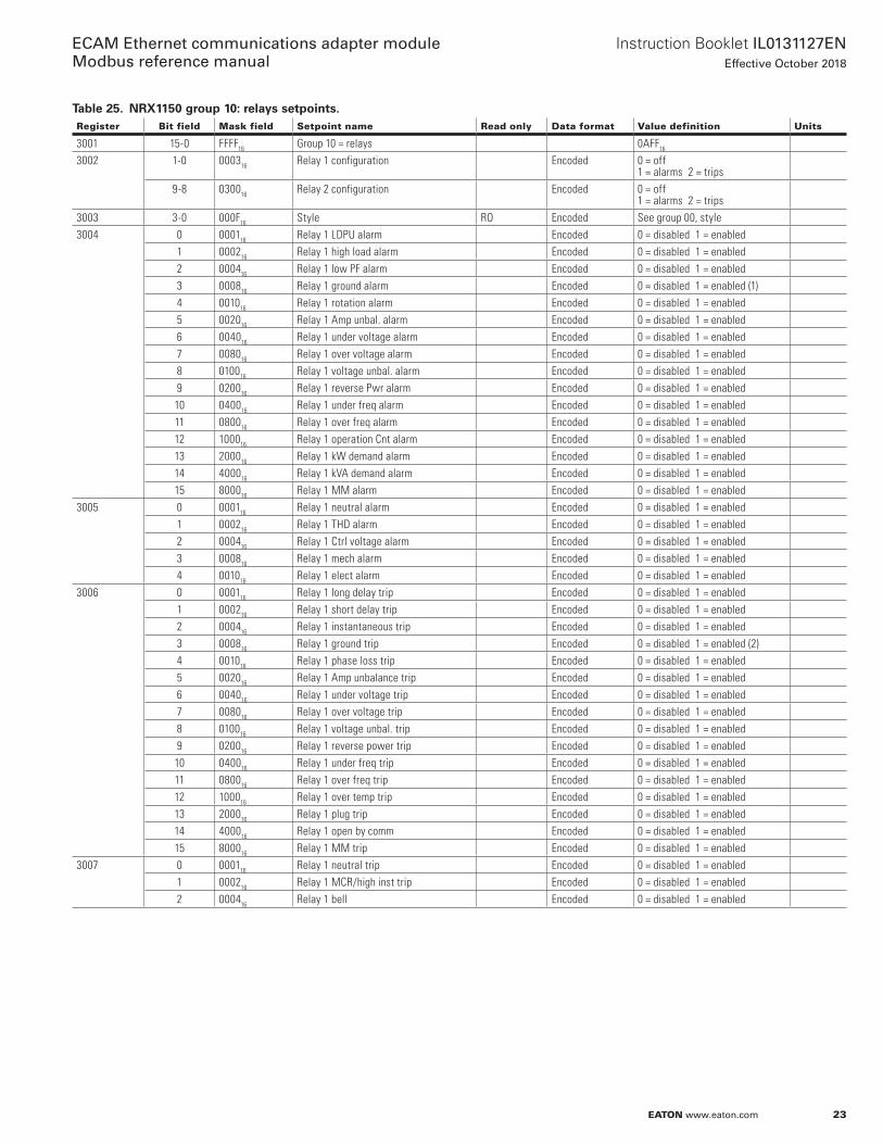
Table 25. NRX1150 group 10: relays setpoints.Register Bit field Mask field Setpoint name Read only Data format Value definition Units
3001 15-0 FFFF16 Group 10 = relays 0AFF16
3002 1-0 000316 Relay 1 configuration Encoded 0 = off 1 = alarms 2 = trips
9-8 030016 Relay 2 configuration Encoded 0 = off 1 = alarms 2 = trips
3003 3-0 000F16 Style RO Encoded See group 00, style3004 0 000116 Relay 1 LDPU alarm Encoded 0 = disabled 1 = enabled
1 000216 Relay 1 high load alarm Encoded 0 = disabled 1 = enabled2 000416 Relay 1 low PF alarm Encoded 0 = disabled 1 = enabled3 000816 Relay 1 ground alarm Encoded 0 = disabled 1 = enabled (1)4 001016 Relay 1 rotation alarm Encoded 0 = disabled 1 = enabled5 002016 Relay 1 Amp unbal. alarm Encoded 0 = disabled 1 = enabled6 004016 Relay 1 under voltage alarm Encoded 0 = disabled 1 = enabled7 008016 Relay 1 over voltage alarm Encoded 0 = disabled 1 = enabled8 010016 Relay 1 voltage unbal. alarm Encoded 0 = disabled 1 = enabled9 020016 Relay 1 reverse Pwr alarm Encoded 0 = disabled 1 = enabled10 040016 Relay 1 under freq alarm Encoded 0 = disabled 1 = enabled11 080016 Relay 1 over freq alarm Encoded 0 = disabled 1 = enabled12 100016 Relay 1 operation Cnt alarm Encoded 0 = disabled 1 = enabled13 200016 Relay 1 kW demand alarm Encoded 0 = disabled 1 = enabled14 400016 Relay 1 kVA demand alarm Encoded 0 = disabled 1 = enabled15 800016 Relay 1 MM alarm Encoded 0 = disabled 1 = enabled
3005 0 000116 Relay 1 neutral alarm Encoded 0 = disabled 1 = enabled1 000216 Relay 1 THD alarm Encoded 0 = disabled 1 = enabled2 000416 Relay 1 Ctrl voltage alarm Encoded 0 = disabled 1 = enabled3 000816 Relay 1 mech alarm Encoded 0 = disabled 1 = enabled4 001016 Relay 1 elect alarm Encoded 0 = disabled 1 = enabled
3006 0 000116 Relay 1 long delay trip Encoded 0 = disabled 1 = enabled1 000216 Relay 1 short delay trip Encoded 0 = disabled 1 = enabled2 000416 Relay 1 instantaneous trip Encoded 0 = disabled 1 = enabled3 000816 Relay 1 ground trip Encoded 0 = disabled 1 = enabled (2)4 001016 Relay 1 phase loss trip Encoded 0 = disabled 1 = enabled5 002016 Relay 1 Amp unbalance trip Encoded 0 = disabled 1 = enabled6 004016 Relay 1 under voltage trip Encoded 0 = disabled 1 = enabled7 008016 Relay 1 over voltage trip Encoded 0 = disabled 1 = enabled8 010016 Relay 1 voltage unbal. trip Encoded 0 = disabled 1 = enabled9 020016 Relay 1 reverse power trip Encoded 0 = disabled 1 = enabled10 040016 Relay 1 under freq trip Encoded 0 = disabled 1 = enabled11 080016 Relay 1 over freq trip Encoded 0 = disabled 1 = enabled12 100016 Relay 1 over temp trip Encoded 0 = disabled 1 = enabled13 200016 Relay 1 plug trip Encoded 0 = disabled 1 = enabled14 400016 Relay 1 open by comm Encoded 0 = disabled 1 = enabled15 800016 Relay 1 MM trip Encoded 0 = disabled 1 = enabled
3007 0 000116 Relay 1 neutral trip Encoded 0 = disabled 1 = enabled1 000216 Relay 1 MCR/high inst trip Encoded 0 = disabled 1 = enabled2 000416 Relay 1 bell Encoded 0 = disabled 1 = enabled
24
Instruction Booklet IL0131127ENEffective October 2018
ECAM Ethernet communications adapter module Modbus reference manual
EATON www.eaton.com
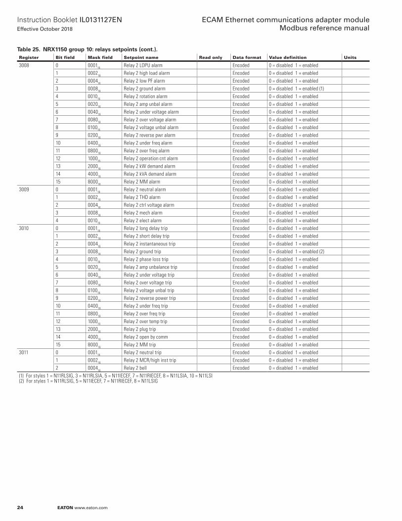
Table 25. NRX1150 group 10: relays setpoints (cont.).Register Bit field Mask field Setpoint name Read only Data format Value definition Units
3008 0 000116 Relay 2 LDPU alarm Encoded 0 = disabled 1 = enabled1 000216 Relay 2 high load alarm Encoded 0 = disabled 1 = enabled2 000416 Relay 2 low PF alarm Encoded 0 = disabled 1 = enabled3 000816 Relay 2 ground alarm Encoded 0 = disabled 1 = enabled (1)4 001016 Relay 2 rotation alarm Encoded 0 = disabled 1 = enabled5 002016 Relay 2 amp unbal alarm Encoded 0 = disabled 1 = enabled6 004016 Relay 2 under voltage alarm Encoded 0 = disabled 1 = enabled7 008016 Relay 2 over voltage alarm Encoded 0 = disabled 1 = enabled8 010016 Relay 2 voltage unbal alarm Encoded 0 = disabled 1 = enabled9 020016 Relay 2 reverse pwr alarm Encoded 0 = disabled 1 = enabled10 040016 Relay 2 under freq alarm Encoded 0 = disabled 1 = enabled11 080016 Relay 2 over freq alarm Encoded 0 = disabled 1 = enabled12 100016 Relay 2 operation cnt alarm Encoded 0 = disabled 1 = enabled13 200016 Relay 2 kW demand alarm Encoded 0 = disabled 1 = enabled14 400016 Relay 2 kVA demand alarm Encoded 0 = disabled 1 = enabled15 800016 Relay 2 MM alarm Encoded 0 = disabled 1 = enabled
3009 0 000116 Relay 2 neutral alarm Encoded 0 = disabled 1 = enabled1 000216 Relay 2 THD alarm Encoded 0 = disabled 1 = enabled2 000416 Relay 2 ctrl voltage alarm Encoded 0 = disabled 1 = enabled3 000816 Relay 2 mech alarm Encoded 0 = disabled 1 = enabled4 001016 Relay 2 elect alarm Encoded 0 = disabled 1 = enabled
3010 0 000116 Relay 2 long delay trip Encoded 0 = disabled 1 = enabled1 000216 Relay 2 short delay trip Encoded 0 = disabled 1 = enabled2 000416 Relay 2 instantaneous trip Encoded 0 = disabled 1 = enabled3 000816 Relay 2 ground trip Encoded 0 = disabled 1 = enabled (2)4 001016 Relay 2 phase loss trip Encoded 0 = disabled 1 = enabled5 002016 Relay 2 amp unbalance trip Encoded 0 = disabled 1 = enabled6 004016 Relay 2 under voltage trip Encoded 0 = disabled 1 = enabled7 008016 Relay 2 over voltage trip Encoded 0 = disabled 1 = enabled8 010016 Relay 2 voltage unbal trip Encoded 0 = disabled 1 = enabled9 020016 Relay 2 reverse power trip Encoded 0 = disabled 1 = enabled10 040016 Relay 2 under freq trip Encoded 0 = disabled 1 = enabled11 080016 Relay 2 over freq trip Encoded 0 = disabled 1 = enabled12 100016 Relay 2 over temp trip Encoded 0 = disabled 1 = enabled13 200016 Relay 2 plug trip Encoded 0 = disabled 1 = enabled14 400016 Relay 2 open by comm Encoded 0 = disabled 1 = enabled15 800016 Relay 2 MM trip Encoded 0 = disabled 1 = enabled
3011 0 000116 Relay 2 neutral trip Encoded 0 = disabled 1 = enabled1 000216 Relay 2 MCR/high inst trip Encoded 0 = disabled 1 = enabled2 000416 Relay 2 bell Encoded 0 = disabled 1 = enabled
(1) For styles 1 = N11RLSIG, 3 = N11RLSIA, 5 = N11IECEF, 7 = N11RIECEF, 8 = N11LSIA, 10 = N11LSI(2) For styles 1 = N11RLSIG, 5 = N11IECEF, 7 = N11RIECEF, 8 = N11LSIG

25
Instruction Booklet IL0131127ENEffective October 2018
ECAM Ethernet communications adapter module Modbus reference manual
EATON www.eaton.com
3.3.5 NRX 520 setpoints
Table 26. NRX520M group 00: setpoints.Register Bit field Mask field Setpoint name Read only Data format Value definition Units
3001 15-0 FFFF16 Group 00 00FF16
3002 2-0 000716 Style RO Encoded 0 = N5MLSI1 = N5MLSIA2 = N5MLSIG3 = N5MRLSI4 = N5MRLSIA5 = N5MRLSIG6 = N5MWLSIG7 = N5MWRLSIG
3003 2-0 000716 Instantaneous RO Encoded 0 = 2 4 = 81 = 3 5 = 102 = 4 6 = 123 = 6 7 = off
A
10-8 070016 Long delay time RO Encoded 0 = 2 4 = 121 = 4 5 = 152 = 7 6 = 203 = 10 7 = 24
Sec
3004 2-0 000716 Long delay pick up = Ir RO Encoded 0 = 0.5 4 = 0.81 = 0.6 5 = 0.92 = 0.7 6 = 0.953 = 0.75 7 = 1.0
A
10-8 070016 Short delay time RO Encoded 0 = 0.1 4 = 0.51 = 0.2 5 = 0.1*2 = 0.3 6 = 0.3*3 = 0.4 7 = 0.5*
sec
3005 2-0 000716 Short delay pick up RO Encoded 0 = 2.0 4 = 6.01 = 3.0 5 = 7.02 = 4.0 6 = 8.03 = 5.0 7 = 10.0
A
8 010016 Maintenance mode RO Encoded 0 = off 1 = on3006 0 000116 Source/residual ground RO Encoded 0 = source 1 = residual
12-8 1F0016 Rating plug = In RO Encoded 00 = 125 16 = 50001 = 150 17 = 60002 = 200 18 = 80003 = 200 19 = 80004 = 250 20 = 100005 = 300 21 = 120006 = 400 22 = 125007 = 400 23 = 160008 = 500 24 = 200009 = 600 25 = 250010 = 630 26 = 300011 = 800 27 = 320012 = 1000 28 = 400013 = 1200 29 = 500014 = 1250 30 = 600015 = 1600 31 = 6400
A
3007 0 000116 Long delay slope RO Encoded 0 = flat 1 = I2T8 010016 Short delay slope RO Encoded 0 = flat 1 = I2T
3008 0 000116 Thermal memory RO Encoded 0 = disabled 1 = enabled8 010016 Frequency RO Encoded 0 = 50 1 = 60 Hz
3009 2-0 000716 Ground fault pick up RO Encoded 0 = 0.25 4 = 0.51 = 0.3 5 = 0.62 = 0.35 6 = 0.753 = 0.4 7 = 1.0
A
10-8 070016 Ground fault time RO Encoded 0 = 0.1 4 = 0.51 = 0.2 5 = 0.1*2 = 0.3 6 = 0.3*3 = 0.4 7 = 0.5*
Sec
3010 0 000116 Ground slope RO Encoded 0 = flat 1 = I2T10-8 070016 Ground fault alarm RO Encoded 0 = 0.25 4 = 0.5
1 = 0.3 5 = 0.62 = 0.35 6 = 0.753 = 0.4 7 = 1.0
A
26
Instruction Booklet IL0131127ENEffective October 2018
ECAM Ethernet communications adapter module Modbus reference manual
EATON www.eaton.com
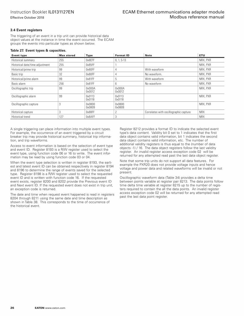
3.4 Event registers
The triggering of an event in a trip unit can provide historical data object values at the instance in time the event occurred . The ECAM groups the events into particular types as shown below .
Table 27. Event types & capacities.Event type Max stored Type Format ID Note ETU
Historical summary 255 0x8EFF 0, 1, 5-13 NRX, PXRHistorical date/time adjustment 255 0x85FF 1 NRX, PXRHistorical/prime trip 99 0x80FF 4 With waveform NRX, PXRBasic trip 32 0x80FF 4 No waveform. NRX, PXRHistorical/prime alarm 99 0x81FF 5 With waveform NRX, PXRBasic alarm 256 0x81FF 6 No waveform NRX, PXROscillographic trip 99 0x000A
0x00120x000A0x0012
NRX, PXR
Oscillographic alarm 99 0x01130x0118
0x01130x0118
NRX, PXR
Oscillographic capture 3 0x08000x0809
0x08000x0809
NRX, PXR
Historical capture 3 0x88FF 2 Correlates with oscillographic capture NRXHistorical trend 127 0x8AFF 3 NRX
A single triggering can place information into multiple event types . For example, the occurrence of an event triggered by a circuit breaker trip may provide historical summary, historical trip informa-tion, and trip waveforms .
Access to event information is based on the selection of event type and event ID . Register 8193 is a R/W register used to select the event type, using function code 06 or 16 to write . The event infor-mation may be read by using function code 03 or 04 .
When the event type selection is written in register 8193, the earli-est and latest event ID can be obtained respectively in register 8194 and 8196 to determine the range of events saved for the selected type . Register 8198 is a R/W register used to select the requested event ID and is written with function code 16 . If the requested event exists, register 8200 and 8202 provide the Previous event ID and Next event ID . If the requested event does not exist in trip unit, an exception code is returned .
The date and time when request event happened is read in registers 8204 through 8211 using the same date and time description as shown in Table 38 . This corresponds to the time of occurrence of the historical event .
Register 8212 provides a format ID to indicate the selected event type’s data content . Validity bit 0 set to 1 indicates that the first data object contains valid information, bit 1 indicates the second data object contains valid information, etc . The number of additional validity registers is thus equal to the (number of data objects -1) / 16 . The data object registers follow the last validity register . An invalid register access exception code 02 will be returned for any attempted read past the last data object register .
Note that some trip units do not support all data features . For example the PXR20 does not provide voltage inputs and hence voltage and power data and related waveforms will be invalid or not present .
Oscillographic waveform data (Table 34) provides a delta time between points variable at register pair 8213 . The data points follow time delta time variable at register 8215 up to the number of regis-ters required to contain the all the data points . An invalid register access exception code 02 will be returned for any attempted read past the last data point register .
27
Instruction Booklet IL0131127ENEffective October 2018
ECAM Ethernet communications adapter module Modbus reference manual
EATON www.eaton.com
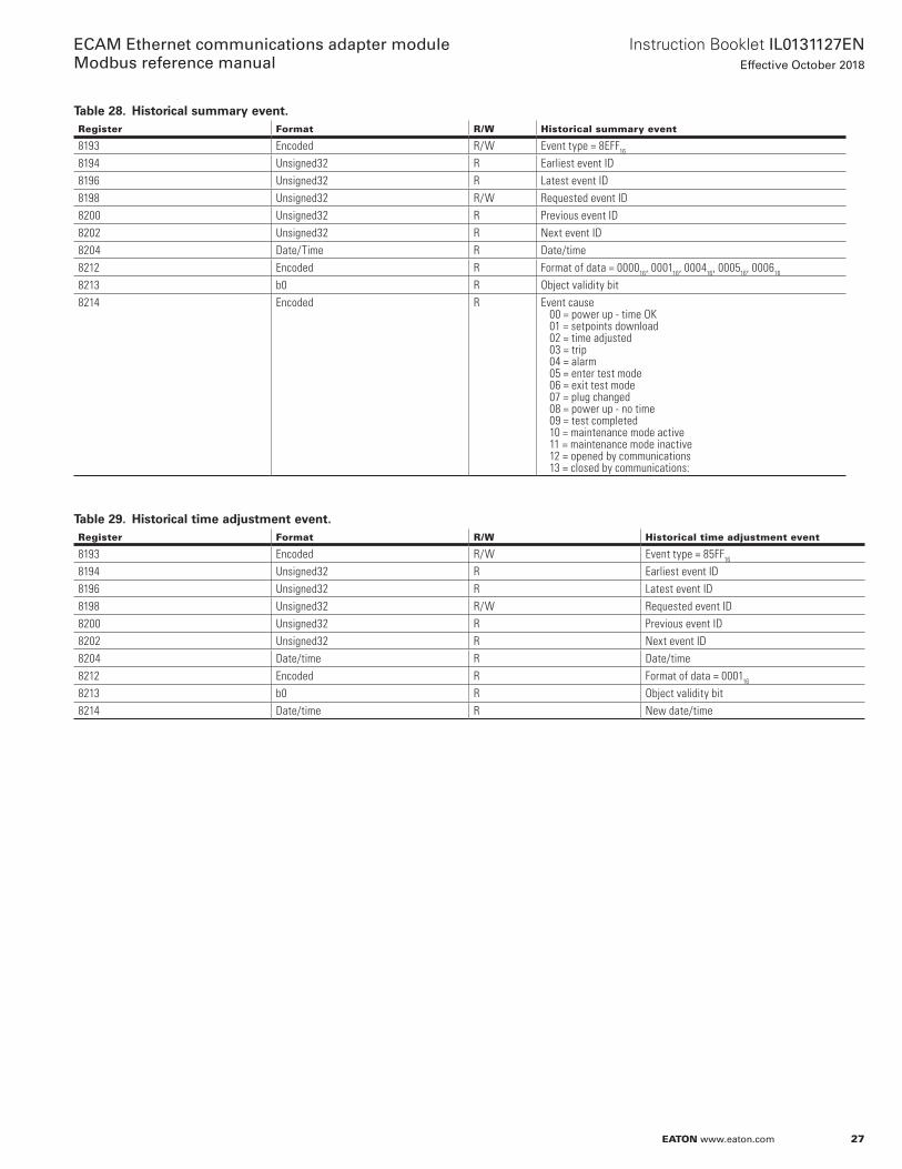
Table 28. Historical summary event.Register Format R/W Historical summary event
8193 Encoded R/W Event type = 8EFF16
8194 Unsigned32 R Earliest event ID8196 Unsigned32 R Latest event ID8198 Unsigned32 R/W Requested event ID8200 Unsigned32 R Previous event ID8202 Unsigned32 R Next event ID8204 Date/Time R Date/time8212 Encoded R Format of data = 000016, 000116, 000416, 000516, 000616
8213 b0 R Object validity bit8214 Encoded R Event cause
00 = power up - time OK 01 = setpoints download 02 = time adjusted 03 = trip 04 = alarm 05 = enter test mode 06 = exit test mode 07 = plug changed 08 = power up - no time 09 = test completed 10 = maintenance mode active 11 = maintenance mode inactive 12 = opened by communications 13 = closed by communications:
Table 29. Historical time adjustment event.Register Format R/W Historical time adjustment event
8193 Encoded R/W Event type = 85FF16
8194 Unsigned32 R Earliest event ID8196 Unsigned32 R Latest event ID8198 Unsigned32 R/W Requested event ID8200 Unsigned32 R Previous event ID8202 Unsigned32 R Next event ID8204 Date/time R Date/time8212 Encoded R Format of data = 000116
8213 b0 R Object validity bit8214 Date/time R New date/time

28
Instruction Booklet IL0131127ENEffective October 2018
ECAM Ethernet communications adapter module Modbus reference manual
EATON www.eaton.com
Table 30. Historical capture event - NRX1150 only.Register Format R/W Historical capture event Units
8193 Encoded R/W Event type = 88FF16
8194 Unsigned32 R Earliest event ID8196 Unsigned32 R Latest event ID8198 Unsigned32 R/W Requested event ID8200 Unsigned32 R Previous event ID8202 Unsigned32 R Next event ID8204 Date/time R Date/time8212 Encoded R Format of data = 000216
8213 b10 – b0 R Object validity bits8214 Encoded R Cause of capture: 00 = network, 01 = display8215 Unsigned16[31] R IA harmonic content: fundamental through 31st harmonic %8246 Unsigned16[31] R IB harmonic content: fundamental through 31st harmonic %8277 Unsigned16[31] R IC harmonic content: fundamental through 31st harmonic %8308 Unsigned16[31] R IN harmonic content: fundamental through 31st harmonic %8339 Unsigned16[31] R VAN harmonic content: fundamental through 31st harmonic %8370 Unsigned16[31] R VBN harmonic content: fundamental through 31st harmonic %8401 Unsigned16[31] R VCN harmonic content: fundamental through 31st harmonic %8432 Unsigned16[31] R VAB harmonic content: fundamental through 31st harmonic %8263 Unsigned16[31] R VBC harmonic content: fundamental through 31st harmonic %8294 Unsigned16[31] R VCA harmonic content: fundamental through 31st harmonic %
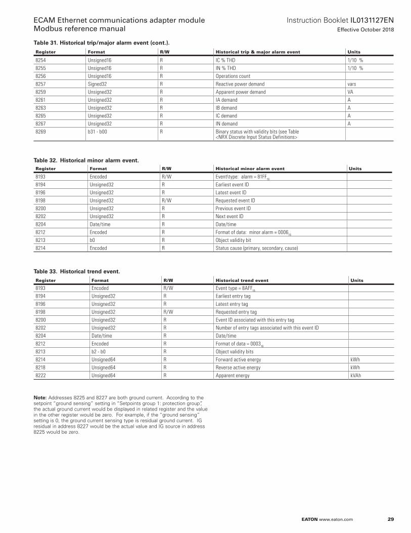
Table 31. Historical trip/major alarm event.Register Format R/W Historical trip & major alarm event Units
8193 Encoded R/W Event Type: Trip = 80FF16 Alarm = 81FF16
8194 Unsigned32 R Earliest event ID8196 Unsigned32 R Latest event ID8198 Unsigned32 R/W Requested event ID8200 Unsigned32 R Previous event ID8202 Unsigned32 R Next event ID8204 Date/time R Date/time8212 Encoded R Format of data: trip = 000416 major alarm = 000516
8213 b15 - b00 R Object validity bits8214 b31 - b16 R Object validity bits8215 Encoded R Status cause (primary, secondary, cause)8217 Unsigned32 R IA A8219 Unsigned32 R IB A8221 Unsigned32 R IC A8223 Unsigned32 R IN A8225 Unsigned32 R IG source A8227 Unsigned32 R IG residual A8229 Unsigned32 R VAB V8231 Unsigned32 R VBC V8233 Unsigned32 R VCA V8235 Unsigned32 R VAN V8237 Unsigned32 R VBN V8239 Unsigned32 R VCN V8241 Signed32 R Real 3 phase power W8243 Signed32 R Real 3 Phase Power Demand W8245 Unsigned32 R Apparent 3 phase power VA8247 Signed16 R Device temperature 1/10 oC8248 Unsigned16 R Frequency 1/10 Hz8249 Signed32 R Reactive 3 phase power vars8251 Signed16 R Apparent power factor 1/100 pf8252 Unsigned16 R IA % THD 1/10 %8253 Unsigned16 R IB % THD 1/10 %
29
Instruction Booklet IL0131127ENEffective October 2018
ECAM Ethernet communications adapter module Modbus reference manual
EATON www.eaton.com
Register Format R/W Historical trip & major alarm event Units
8254 Unsigned16 R IC % THD 1/10 %8255 Unsigned16 R IN % THD 1/10 %8256 Unsigned16 R Operations count8257 Signed32 R Reactive power demand vars8259 Unsigned32 R Apparent power demand VA8261 Unsigned32 R IA demand A8263 Unsigned32 R IB demand A8265 Unsigned32 R IC demand A8267 Unsigned32 R IN demand A8269 b31 - b00 R Binary status with validity bits (see Table
<NRX Discrete Input Status Definitions>
Table 32. Historical minor alarm event.Register Format R/W Historical minor alarm event Units
8193 Encoded R/W Event\type: alarm = 81FF16
8194 Unsigned32 R Earliest event ID8196 Unsigned32 R Latest event ID8198 Unsigned32 R/W Requested event ID8200 Unsigned32 R Previous event ID8202 Unsigned32 R Next event ID8204 Date/time R Date/time8212 Encoded R Format of data: minor alarm = 000616
8213 b0 R Object validity bit8214 Encoded R Status cause (primary, secondary, cause)
Table 33. Historical trend event.
Register Format R/W Historical trend event Units
8193 Encoded R/W Event type = 8AFF16
8194 Unsigned32 R Earliest entry tag8196 Unsigned32 R Latest entry tag8198 Unsigned32 R/W Requested entry tag8200 Unsigned32 R Event ID associated with this entry tag8202 Unsigned32 R Number of entry tags associated with this event ID8204 Date/time R Date/time8212 Encoded R Format of data = 000316
8213 b2 - b0 R Object validity bits8214 Unsigned64 R Forward active energy kWh8218 Unsigned64 R Reverse active energy kWh8222 Unsigned64 R Apparent energy kVAh
ote:N Addresses 8225 and 8227 are both ground current . According to the setpoint “ground sensing” setting in “Setpoints group 1: protection group”, the actual ground current would be displayed in related register and the value in the other register would be zero . For example, if the “ground sensing” setting is 0, the ground current sensing type is residual ground current . IG residual in address 8227 would be the actual value and IG source in address 8225 would be zero .
Table 31. Historical trip/major alarm event (cont.).

30
Instruction Booklet IL0131127ENEffective October 2018
ECAM Ethernet communications adapter module Modbus reference manual
EATON www.eaton.com
Table 34. Oscillographic waveform events.
Register Encoded R/W Oscillographic event type Data format
Number of points NRX/PXR-ACB/PXR-MCCB Units
8193 00xx16 = trip event01xx16 = alarm event 08xx16 = capture event 0016 = IA captured waveform 0116 = IB captured waveform 0216 = IC captured waveform 0316 = IN captured waveform 0416 = VAN captured waveform 0516 = VBN captured waveform 0616 = VCN captured waveform 0716 = VAB captured waveform 0816 = VBC captured waveform 0916 = VCA captured waveform 0A16 = IA trip waveform 0B16 = IB trip waveform 0C16 = IC trip waveform 0D16 = IN trip waveform 0E16 = IG source trip waveform 0F16 = IG residual trip waveform 1016 = VAB trip waveform 1116 = VBC trip waveform 1216 = VCA trip waveform 1316 = IA alarm waveform 1416 = IB alarm waveform 1516 = IC alarm waveform 1616 = IN alarm waveform 1716 = IG source alarm waveform 1816 = IG residual alarm waveform1916 = VAB alarm waveform 1A16 = VBC alarm waveform 1B16 = VCA alarm waveform
IEEE floatIEEE floatIEEE floatIEEE floatIEEE floatIEEE floatIEEE floatIEEE floatIEEE floatIEEE floatIEEE floatIEEE floatIEEE floatIEEE floatIEEE floatIEEE floatIEEE floatIEEE floatIEEE floatIEEE floatIEEE floatIEEE floatIEEE floatIEEE floatIEEE floatIEEE floatIEEE floatIEEE float
64/64/7264/64/7264/64/7264/64/7264/64/7264/64/7264/64/7264/64/7264/64/7264/64/72640/384/720640/384/720640/384/720640/384/720640/384/720640/384/720640/384/720640/384/720640/384/720384/64/72384/64/72384/64/72384/64/72384/64/72384/64/72384/64/72384/64/72384/64/72
AAAAVVVVVVAAAAAAVVVAAAAAAVVV
8194 Unsigned32 R Earliest event ID8196 Unsigned32 R Latest event ID8198 Unsigned32 R/W Requested event ID8200 Unsigned32 R Previous event ID8202 Unsigned32 R Next event ID8204 Date/time R Date/time8212 Encoded R Format of data (= event type)8213 IEEE float R Delta time between points sec8215 Data format [xx] R Data points
Note: Voltage waveforms are not available on PXR20 models.
3.4.1 Block of registers
A block of registers can be established to remap the data object registers to different register addresses . The block of registers is stored in non-volatile memory and is retained between power cycles .
Function code 16 is used to load the object assignments for the block of registers . The block assignments are stored beginning at 1001/20481 . Only the first data object register address is assigned within the block of registers . For example, although data object IA occupies register 4611 and 4612, only register 4611 is loaded into the block of assignment registers . Verification of this block of assignment registers can be read from trip unit with a function code 03 or 04 from these 1001/20481 registers .
Data pertaining to the objects configured in the block of assign-ment registers is mapped into registers starting at 1201/20737 and continuing in successive order for each object assigned . The number of objects and their placement order in this data block of registers is dependent on the configuration of the block of assignment registers . The total number of data block of registers is limited to 100 .
The data can be obtained from the data block of registers by a read function code 03 or 04 . The address of the starting object must be aligned with a starting address of an object within the data block of registers . The number of registers to obtain must align with an ending address of an object within the data block of registers .
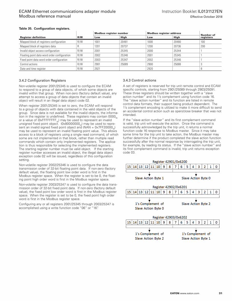
31
Instruction Booklet IL0131127ENEffective October 2018
ECAM Ethernet communications adapter module Modbus reference manual
EATON www.eaton.com
Table 35. Configuration registers.
Register definition R/W
Modbus register number Modbus register addressNumber of registersLow High Low High
Mapped block of registers configuration R/W 1001 20481 1000 20480 100Mapped block of registers data R 1201 20737 1200 20736 200Invalid object access configuration R/W 2001 25345 2000 25344 1Floating point data word order configuration R/W 2002 25346 2001 25345 1Fixed point data word order configuration R/W 2003 25347 2002 25346 1Control actions R/W 2901 25089 2900 25088 3Date and time register R/W 2921 2920 8
3.4.2 Configuration Registers
Non-volatile register 2001/25345 is used to configure the ECAM to respond to a group of data objects, of which some objects are invalid within that group . When non-zero (factory default value), any attempt to access a group of data objects that contain an invalid object will result in an illegal data object code 02 .
When register 2001/25345 is set to zero, the ECAM will respond to a group of objects with data contained in the valid objects of the group . Since data is not available for the invalid objects, the informa-tion in the register is undefined . These registers may contain 000016 or a value of (0xFFFFFFFF16) may be used to represent an invalid unsigned fixed point object . (0x8000000016) may be used to repre-sent an invalid signed fixed point object and (NAN = 0x7FF2000016) may be used to represent an invalid floating point value . This allows access to a block of registers using a single read command, of which some are not implemented in that block, rather than multiple read commands which contain only implemented registers . The applica-tion is thus responsible for selecting the implemented registers . The starting register number must be valid object . If the starting register number accesses an invalid object, the illegal data object exception code 02 will be issued, regardless of this configuration setting .
Non-volatile register 2002/25346 is used to configure the data transmission order of 32-bit floating point data . If non-zero (factory default value), the floating point low order word is first in the Modbus register space . When the register is set to be 0, the float-ing point high order word is first in the Modbus register space .
Non-volatile register 2003/25347 is used to configure the data trans-mission order of 32-bit fixed point data . If non-zero (factory default value), the fixed point low order word is first in the Modbus register space . When the register is set to be 0, the fixed point high order word is first in the Modbus register space .
Configuring any or all registers 2001/25345 through 2003/25347 is accomplished using a write function code “06” or “16” .
3.4.3 Control actions
A set of registers is reserved for trip unit remote control and ECAM specific controls, starting from 2901/25089 through 2903/25091 . These three registers should be written together with a “slave action number” and its 1’s complement using function code 16 . The “slave action number” and its function are listed in remote control data formats, their support being product dependent . The 1’s complement encoding is utilized to make it more difficult to send an accidental control action such as open/close breaker that was not intended .
If the “slave action number” and its first complement command is valid, trip unit will execute the action . Once the command is successfully acknowledged by the trip unit, it returns a normal function code 16 response to Modbus master . Since it may take some time for the trip unit to take action, the Modbus master may further determine if the product completed the slave action function successfully after the normal response by interrogating the trip unit, for example, by reading its status . If the “slave action number” and its first complement command is invalid, trip unit returns exception code 03 .
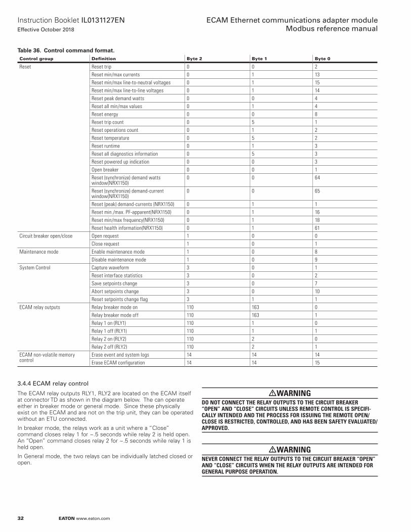
32
Instruction Booklet IL0131127ENEffective October 2018
ECAM Ethernet communications adapter module Modbus reference manual
EATON www.eaton.com
Table 36. Control command format.Control group Definition Byte 2 Byte 1 Byte 0
Reset Reset trip 0 0 2Reset min/max currents 0 1 13Reset min/max line-to-neutral voltages 0 1 15Reset min/max line-to-line voltages 0 1 14Reset peak demand watts 0 0 4Reset all min/max values 0 1 4Reset energy 0 0 8Reset trip count 0 5 1Reset operations count 0 1 2Reset temperature 0 5 2Reset runtime 0 1 3Reset all diagnostics information 0 5 3Reset powered up indication 0 0 3Open breaker 0 0 1Reset (synchronize) demand watts window(NRX1150)
0 0 64
Reset (synchronize) demand-current window(NRX1150)
0 0 65
Reset (peak) demand-currents (NRX1150) 0 1 1Reset min./max. PF-apparent(NRX1150) 0 1 16Reset min/max frequency(NRX1150) 0 1 18Reset health information(NRX1150) 0 1 61
Circuit breaker open/close Open request 1 0 0Close request 1 0 1
Maintenance mode Enable maintenance mode 1 0 8Disable maintenance mode 1 0 9
System Control Capture waveform 3 0 1Reset interface statistics 3 0 2Save setpoints change 3 0 7Abort setpoints change 3 0 10Reset setpoints change flag 3 1 1
ECAM relay outputs Relay breaker mode on 110 163 0Relay breaker mode off 110 163 1Relay 1 on (RLY1) 110 1 0Relay 1 off (RLY1) 110 1 1Relay 2 on (RLY2) 110 2 0Relay 2 off (RLY2) 110 2 1
ECAM non-volatile memory control
Erase event and system logs 14 14 14Erase ECAM configuration 14 14 15
3.4.4 ECAM relay control
The ECAM relay outputs RLY1, RLY2 are located on the ECAM itself at connector TD as shown in the diagram below . The can operate either in breaker mode or general mode . Since these physically exist on the ECAM and are not on the trip unit, they can be operated without an ETU connected .
In breaker mode, the relays work as a unit where a “Close” command closes relay 1 for ~ .5 seconds while relay 2 is held open . An “Open” command closes relay 2 for ~ .5 seconds while relay 1 is held open .
In General mode, the two relays can be individually latched closed or open .
mWARNINGDO NOT CONNECT THE RELAY OUTPUTS TO THE CIRCUIT BREAKER “OPEN” AND “CLOSE” CIRCUITS UNLESS REMOTE CONTROL IS SPECIFI-CALLY INTENDED AND THE PROCESS FOR ISSUING THE REMOTE OPEN/CLOSE IS RESTRICTED, CONTROLLED, AND HAS BEEN SAFETY EVALUATED/APPROVED.
mWARNINGNEVER CONNECT THE RELAY OUTPUTS TO THE CIRCUIT BREAKER “OPEN” AND “CLOSE” CIRCUITS WHEN THE RELAY OUTPUTS ARE INTENDED FOR GENERAL PURPOSE OPERATION.
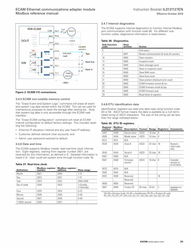
33
Instruction Booklet IL0131127ENEffective October 2018
ECAM Ethernet communications adapter module Modbus reference manual
EATON www.eaton.com
Figure 2. ECAM I/O connections.
3.4.5 ECAM non-volatile memory control
The “Erase Event and System Logs” command will erase all event and system Log data stored within the ECAM . This can be used for maintenance purposes to reset the storage after testing etc . Note that system log data is only accessible through the ECAM web interface .
The “Erase ECAM configuration” command will reset all ECAM internal configuration to default factory settings . This includes reset-ting the following:• Ethernet IP allocation method and any user fixed IP address;• Customer defined network User accounts; and• Admin user password restored to default .
3.4.6 Date and time
The ECAM supports Modbus master read real-time clock informa-tion . Eight registers, starting from register number 2921, are reserved for this information, as defined in 0 . Detailed information is listed in 0 . User could set system time through function code 16 .
Table 37. Real-time clock.
DefinitionModbus register number
Modbus register address Data range
Month 2921 2920 1-12Day 2922 2921 1-31Year 2923 2922 2000-2099Day of week 2924 2923 1=Sunday…
7=SaturdayHour 2925 2924 0-23Minute 2926 2925 0-59Second 2927 2926 0-591/100th second 2928 2927
3.4.7 Internal diagnostics
The ECAM supports internal diagnostics to monitor internal Modbus port communication with function code 08 . For different sub-function codes, diagnostics information is listed below .
Table 38. Diagnostics.Sub-function code
Data written Action
0 Echo query1 00FF Restart communication & reset all counters10 0000 Clear counters13 0000 Exception count14 0000 Slave message count15 0000 Slave no response count16 0000 Slave NAK count17 0000 Slave busy count21 0000 Slave product checksum error count26 0000 ECAM firmware version & rev27 0000 ECAM firmware month & day28 0000 ECAM firmware year29 0000 Reset block of registers
3.4.8 ETU identification data
Identification registers are read only data read using function code 03 or 04 . ASCII format means the data is available as a null termi-nated string of ASCII characters . The size of the string can be less than the range indicated below .
Table 39. ETU ID registers.Register number
Modbus address Description Format Range Registers Comments
4497 4496 Device name ASCII 16 char 84505 4504 Model name ASCII 16 char 84513 4512 N/A4529 4528 Style # ASCII 32 char 16 Numeric
style code only
4545 4544 Serial # ASCII 32 char 164561 4560 N/A4567 4566 Firmware
version 1ASCII 16 char 8 Example
version of 01.02.0033
4575 4574 N/A4583 4582 N/A4591 4590 Reserved 16
… Reserved4606 4605 Reserved4607 4606 Product ID Bit map 32-bit 2 ppppppvvvv
dddddd1
1 D5-D0=>Division Code; V3-V0 =>ComVersion; P5-P0 =>Product ID code P5 | P4 | P3 | P2 | P1 | P0 | V3 | V2 | V1 | V0 | D5 | D4 | D3 | D2 | D1 | D0
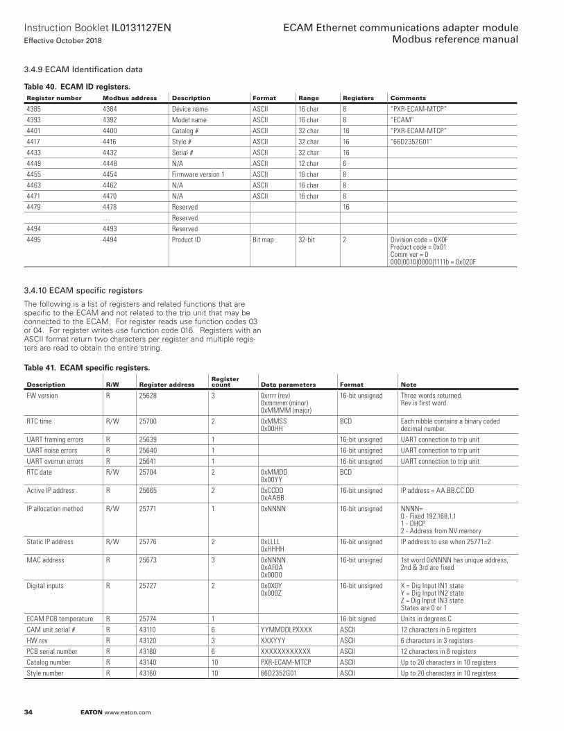
34
Instruction Booklet IL0131127ENEffective October 2018
ECAM Ethernet communications adapter module Modbus reference manual
EATON www.eaton.com
3.4.9 ECAM Identification data
Table 40. ECAM ID registers.Register number Modbus address Description Format Range Registers Comments
4385 4384 Device name ASCII 16 char 8 “PXR-ECAM-MTCP”4393 4392 Model name ASCII 16 char 8 “ECAM”4401 4400 Catalog # ASCII 32 char 16 “PXR-ECAM-MTCP”4417 4416 Style # ASCII 32 char 16 “66D2352G01”4433 4432 Serial # ASCII 32 char 164449 4448 N/A ASCII 12 char 64455 4454 Firmware version 1 ASCII 16 char 84463 4462 N/A ASCII 16 char 84471 4470 N/A ASCII 16 char 84479 4478 Reserved 16
… Reserved4494 4493 Reserved4495 4494 Product ID Bit map 32-bit 2 Division code = 0X0F
Product code = 0x01Comm ver = 0000|0010|0000|1111b = 0x020F
3.4.10 ECAM specific registers
The following is a list of registers and related functions that are specific to the ECAM and not related to the trip unit that may be connected to the ECAM . For register reads use function codes 03 or 04 . For register writes use function code 016 . Registers with an ASCII format return two characters per register and multiple regis-ters are read to obtain the entire string .
Table 41. ECAM specific registers.
Description R/W Register addressRegister count Data parameters Format Note
FW version R 25628 3 0xrrrr (rev) 0xmmmm (minor) 0xMMMM (major)
16-bit unsigned Three words returned. Rev is first word.
RTC time R/W 25700 2 0xMMSS0x00HH
BCD Each nibble contains a binary coded decimal number.
UART framing errors R 25639 1 16-bit unsigned UART connection to trip unitUART noise errors R 25640 1 16-bit unsigned UART connection to trip unitUART overrun errors R 25641 1 16-bit unsigned UART connection to trip unitRTC date R/W 25704 2 0xMMDD
0x00YYBCD
Active IP address R 25665 2 0xCCDD0xAABB
16-bit unsigned IP address = AA.BB.CC.DD
IP allocation method R/W 25771 1 0xNNNN 16-bit unsigned NNNN=0 - Fixed 192.168.1.11 - DHCP2 - Address from NV memory
Static IP address R/W 25776 2 0xLLLL0xHHHH
16-bit unsigned IP address to use when 25771=2
MAC address R 25673 3 0xNNNN0xAF0A 0x00D0
16-bit unsigned 1st word 0xNNNN has unique address, 2nd & 3rd are fixed
Digital inputs R 25727 2 0x0X0Y0x000Z
16-bit unsigned X = Dig Input IN1 stateY = Dig Input IN2 stateZ = Dig Input IN3 stateStates are 0 or 1
ECAM PCB temperature R 25774 1 16-bit signed Units in degrees CCAM unit serial # R 43110 6 YYMMDDLPXXXX ASCII 12 characters in 6 registersHW rev R 43120 3 XXXYYY ASCII 6 characters in 3 registersPCB serial number R 43180 6 XXXXXXXXXXXX ASCII 12 characters in 6 registersCatalog number R 43140 10 PXR-ECAM-MTCP ASCII Up to 20 characters in 10 registersStyle number R 43160 10 66D2352G01 ASCII Up to 20 characters in 10 registers
35
Instruction Booklet IL0131127ENEffective October 2018
ECAM Ethernet communications adapter module Modbus reference manual
EATON www.eaton.com
3.4.11 IP address
The active IP address can be read from two registers starting at address 25665 . This is helpful if the IP address cannot be read from the trip unit display .
For example:
If 0x0ED8 is read from 25665 and 0x0A82 is read from 25666 this represents IP address 10 .130 .14 .216
Table 42. ECAM IP address example decodeRegister 25665 (low word= 3rd & 4th octets)
Register 25666 (high word = 1st & 2nd octets)
Hex 0E D8 0A 82Decimal 14 216 10 130
3.4.12 IP address allocation (USB port only)
The IP address allocation method is set by writing to register 25771 and selecting either fixed IP address or dynamic (DHCP):
0 - Fixed default 192 .168 .1 .1;
1 - DHCP - network assigned;
2 - Address from NV memory .
For example, to set a fixed IP address:
1 . Write desired IP address to 25776 as two words (low word/octets first) .
2 . Write a 2 to register address 25771 ( take address from NV memory) .
3 . Reboot ECAM (power cycle) .
To set for dynamic/DHCP IP:
1 . Write a 1 to register address 25771 (dynamic allocation) .
2 . Reboot ECAM (power cycle) .
3.4.13 Dig inputs description
The ECAM 24 V digital inputs IN1, IN2, and IN3 are available at connector at TD pins 4, 3, 2 respectively (see Figure 2 . ECAM I/O connections) . They physically exist on the ECAM and are not related to the ETU . To activate an input, 24 Vdc is applied between the input pin and the common return at TD .1 . The table below indicates the read register values expected for the possible states of the 3 inputs .
Table 43. Dig inputs truth table.
IN3 (TD.4)
IN2 (TD.3)
IN1 (TD.2)
IN4 (TD.1)
Register 25727 reading
Register 25728 reading
0 0 0 Gnd 0x0000 0x00000 0 24 Gnd 0x0001 0x00000 24 0 Gnd 0x0100 0x00000 24 24 Gnd 0x0101 0x000024 0 0 Gnd 0x0000 0x000124 0 24 Gnd 0x0001 0x000124 24 0 Gnd 0x0100 0x000124 24 24 Gnd 0x0101 0x0001

Eaton1000 Eaton BoulevardCleveland, OH 44122United StatesEaton .com
© 2018 EatonAll Rights ReservedPrinted in USAPublication No . IL0131127EN / TBG 001410October 2018
Eaton is a registered trademark.
All other trademarks are property of their respective owners.
ECAM Ethernet communications adapter module Modbus reference manual
Instruction Booklet IL0131127ENEffective October 2018
DISCLAIMER OF WARRANTIES AND LIMITATION OF LIABILITY
The information, recommendations, descriptions and safety nota-tions in this document are based on Eaton Corporation’s (“Eaton”) experience and judgment and may not cover all contingencies . If further information is required, an Eaton sales office should be consulted . Sale of the product shown in this literature is subject to the terms and conditions outlined in appropriate Eaton selling policies or other contractual agreement between Eaton and the purchaser .
THERE ARE NO UNDERSTANDINGS, AGREEMENTS, WARRANTIES, EXPRESSED OR IMPLIED, INCLUDING WARRANTIES OF FITNESS FOR A PARTICULAR PURPOSE OR MERCHANTABILITY, OTHER THAN THOSE SPECIFICALLY SET OUT IN ANY EXISTING CONTRACT BETWEEN THE PARTIES . ANY SUCH CONTRACT STATES THE ENTIRE OBLIGATION OF EATON . THE CONTENTS OF THIS DOCUMENT SHALL NOT BECOME PART OF OR MODIFY ANY CONTRACT BETWEEN THE PARTIES .
In no event will Eaton be responsible to the purchaser or user in contract, in tort (including negligence), strict liability or other-wise for any special, indirect, incidental or consequential damage or loss whatsoever, including but not limited to damage or loss of use of equipment, plant or power system, cost of capital, loss of power, additional expenses in the use of existing power facilities, or claims against the purchaser or user by its customers resulting from the use of the information, recommendations and descriptions contained herein . The information contained in this manual is subject to change without notice .


![DPU2000/1500R/2000R MODBUS / MODBUS PLUS … · DPU2000/1500R/2000R Modbus/Modbus Plus Automation Guide i DPU2000/1500R/2000R MODBUS / MODBUS PLUS ... [Catalog 587XXX00-XXX0 or 587XXXX6-XXX4]](https://static.fdocuments.us/doc/165x107/5acb9eac7f8b9a73128bdc42/dpu20001500r2000r-modbus-modbus-plus-modbusmodbus-plus-automation-guide.jpg)


