

EBA-12 EBA-12 S - beveling machines and bevel heads · 2 1.1 General notes on safety This operation...
13
www.beveltools.com 01-2014 EBA-12 EBA-12 S Instruction Manual
Transcript of EBA-12 EBA-12 S - beveling machines and bevel heads · 2 1.1 General notes on safety This operation...
1
Content
1.1 General Notes of safety 1.2 Use of the machine for purposes for which it is intended 1.3 Incorrect use 1.4 CE declaration of conformity 1.5 Symbol legend 2.1 Prior to taking the machine into service 2.2 Taking the machine into service 2.3 Rating data 2.4 Operating conditions 3.1 Protection devices 3.2 Beveling tool 3.3 Working instructions 4.1 Preventive maintenance 4.2 Repair 4.3 Warranty 4.4 Storage 4.5 Disposal / Environmental compatibility 4.6 Maintenance and wearing parts

2
1.1 General notes on safety This operation manual is applicable for the machines EBA-12 EBA-12S The machines may only be handled by personnel who are qualified. Hold power tools by insulated gripping surfaces when performing an operation where the cutting tool may contact hidden wiring or its own cord. Contact with a «live» wire will make exposed metal parts of the tool «live» and shock the operator. WARNING Read all safety warnings and all instructions. Failure to follow the warnings and instructions may result in electric shock, fire and/or serious injury. Save all warnings and instructions for future reference. 1.2 Use of the machine for purposes for which it is intended The machines are intended for the purpose of beveling of metal and plastic materials without the use of water. 1.3 Incorrect use All uses other than those described under section 1.2 are regarded as incorrect use and are therefore not admissible. 1.4 CE declaration of conformity Beveltools BV of P.O.box 190, 6880 AD Velp Gld, hereby declares under sole responsibility that the product with the serial or batch no. (see reverse side) complies with the requirements under the Directive 2004/108/EC, 2006/42/EC, 2011/65/EU. Applied standards: EN ISO 12100, EN 60745, EN 55014-1, EN 55014-2, EN 61000-3-2, EN 61000-3-3. Document Agent: J.E. Hofman, July 2014 J.E. Hofman Managing Director 1.5 Symbol legend Attention! Make sure to read! This information is very important for ensuring correct operation of the product. Failure to observe this information can result in a defect. Note on safety / Warning This information serves to achieve safe operation. Failure to observe this information may compromise the operator‘s safety. Information This information serves for a good understanding of the operation of the product, thereby permitting full exploitation of the operational potential of the product. Technical Document Read the technical document prior to commissioning. Safety glasses and ear protection. Wear safety glasses and ear protection.

3
Disposal Friendly-to-the-environment disposal. Power connector Before any work is carried out on the machine, disconnect the power connector. 2.1 Prior to taking the machine into service Before connecting tool to a power source, be sure the voltage supplied is the same as specified on the name plate of the tool. The power supply should not vary more than 10% above or below the voltage indicated on the nameplate. Working with worn or damaged router heads will cause the machine to fail. • Check beveling tool prior to use. • Sharp beveling tools will increase cutting speed and machine life. • Beveling tools must be changed regularly. • The beveling tool must be mounted centrally and positioned against the limit stop. • The maximum allowable speed of the tool and of the chuck may not be exceeded under any circumstances. • Observe national regulations. 2.2 Taking the machine into service
Preselect speed with adjusting wheel according to speed table.
Adjusting wheel increment Min-1 / rpm
1 4.200
2 5.200
3 6.400
4 7.600
5 8.800
6 10.000
During operation never increase the speed of the machine to above that of the maximum admissible speed of the grinding tool!

4
2.2.1 Turn on
• Make sure you always have a firm footing when working with the machine. • Whatever the position of the machine, always use two hands to control the machine. • Never touch the milling head when the machine is running. • Never use the machine above head height. • The machine should only be used for conventional up‐cut milling. • To turn the machine on, push the ON/OFF switch toward the front. • Bring the machine slowly into contact with the work piece only after the selected tool speed has been reached. • When cutting a bevel always move the machine from left to right against the direction of rotation of the milling head. • When machining bore holes, always work in a clockwise direction. 2.2.2 Turn off • Take Beveling machine from work peace and turn off. • Motor stops. 2.3 Rating data
Power voltage (cf. replacement parts list) 120/230V; 50/60 Hz; 120/230V
Power Input 1530 W
Power Output 1000 W
No-load speed 10500 min-1/rpm
Max. wheel diameter 45 mm
Grinding spindle thread M8
Sound pressure level according to EN 60745 89 dB (A) K = 3 dB
Noise emission level 100 dB (A) K = 3 dB
Vibration according to EN 60745 <2.5 m/s2 K = 1.5m/s2
Weight w/o cord set 4.3 kg
Protection class / II
The specified vibration value was measured with a standardized test procedure. It can be used to compare products or to make an initial assessment of the exposure. The vibration emissions may differ from the specified value, depending on how the power tool is used. Operating personnel must be protected with defined safety measures based on the estimated exposure under the actual conditions of use (these must take into account all phases of the operating cycle, e.g. the times when the power tool is switched OFF and the times it is switched ON, but is not under load).

5
2.4 Operating conditions Temperature range during operation: 0 to +50°C Relative air humidity: 95% at +10°C not condensed 3.1 Protective devices The machine may only be operated with the Flange head and the additional handle fitted! 3.1.1 Flange head
Adapt Flange head • Turn the Flange head until it has reached the right depth. • Rotate the guide plate until the required bevel height has been set as shown by the fixed main scale. Cleaning depth mechanism • Remove guide bearing and bevel head. • Turn the Flange head until it comes off. • Clean all parts and replace defective parts. • Lubricate the thread with Teflon spray and gears with a little multi-purpose grease. • Re‐assemble in reverse order. 3.1.2 Additional handle
The additional handle must be screwed in at the left and right with the supplied screws.
6
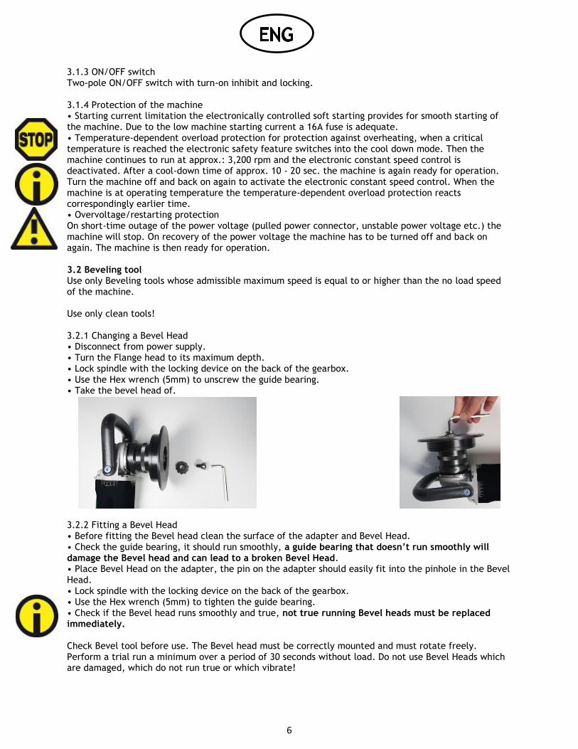
3.1.3 ON/OFF switch Two-pole ON/OFF switch with turn-on inhibit and locking. 3.1.4 Protection of the machine • Starting current limitation the electronically controlled soft starting provides for smooth starting of the machine. Due to the low machine starting current a 16A fuse is adequate. • Temperature-dependent overload protection for protection against overheating, when a critical temperature is reached the electronic safety feature switches into the cool down mode. Then the machine continues to run at approx.: 3,200 rpm and the electronic constant speed control is deactivated. After a cool-down time of approx. 10 - 20 sec. the machine is again ready for operation. Turn the machine off and back on again to activate the electronic constant speed control. When the machine is at operating temperature the temperature-dependent overload protection reacts correspondingly earlier time. • Overvoltage/restarting protection On short-time outage of the power voltage (pulled power connector, unstable power voltage etc.) the machine will stop. On recovery of the power voltage the machine has to be turned off and back on again. The machine is then ready for operation. 3.2 Beveling tool Use only Beveling tools whose admissible maximum speed is equal to or higher than the no load speed of the machine. Use only clean tools! 3.2.1 Changing a Bevel Head • Disconnect from power supply. • Turn the Flange head to its maximum depth. • Lock spindle with the locking device on the back of the gearbox. • Use the Hex wrench (5mm) to unscrew the guide bearing. • Take the bevel head of.
3.2.2 Fitting a Bevel Head • Before fitting the Bevel head clean the surface of the adapter and Bevel Head. • Check the guide bearing, it should run smoothly, a guide bearing that doesn’t run smoothly will damage the Bevel head and can lead to a broken Bevel Head. • Place Bevel Head on the adapter, the pin on the adapter should easily fit into the pinhole in the Bevel Head. • Lock spindle with the locking device on the back of the gearbox. • Use the Hex wrench (5mm) to tighten the guide bearing. • Check if the Bevel head runs smoothly and true, not true running Bevel heads must be replaced immediately. Check Bevel tool before use. The Bevel head must be correctly mounted and must rotate freely. Perform a trial run a minimum over a period of 30 seconds without load. Do not use Bevel Heads which are damaged, which do not run true or which vibrate!

7
3.3 Working instructions • To achieve an optimum Bevel result, move Bevel tool uniformly with light pressure. • The electronic constant control maintains the speed nearly constant during idling and work under load and assures a uniform result. • Excessive pressure lessens the working capability of the machine, as well as the life of the Bevel tool. • The machine is equipped with an electronic control and integrated overload protection. • If the machine is overloaded, the speed will drop drastically. Immediately take the load off the machine and allow to run for a short time without load. Maximum depth per cut, on steel, no more than 4mm with a maximum Power-on time of 50%. 4.1 Preventive maintenance • To work effectively and surely keep the machine and the ventilation slots clean at all times. • After approx. 200 operating hours check carbon brushes and replace if necessary. Clean motor housing and replenish grease filling in gearbox housing. When the brushes are spent, the machine will stop automatically. • To maintain the protective insulation the machine must be subjected to a technical safety inspection. This work must be done exclusively by a specialized electrical workshop. • When working on metal under extreme working conditions conductive dust deposits can occur inside the machine, thereby impairing the protective insulation of the machine. In such cases the use of a stationary vacuuming system, frequent blowing out of the ventilation slots and protection by a fault current protection switch are advised. 4.1.1 Changing the carbon brushes The Automatic-Stop feature protects the machine from defects due to excessively consumed carbon brushes. The machine is equipped with two carbon brushes, i.e. one is installed in each handle half. The carbon brushes must be changed as follows:
• Unscrew four screws and remove the handle halves. • Lift spring with screwdriver and remove brush. Install new brushes. Clean carbon brush holders, making absolutely sure not to change the arrangement of the elements of the carbon brush assembly. • Fit handle halves and fasten with four screws. • Repeat this change on the opposite side, making absolutely sure to avoid both handle halves from being opened at the same time.

8
4.2 Repair
If despite strict observance of the manufacturing and testing method the tool should happen to fail, it
must be repaired by an authorized agency. Any replacement needed for the connecting line must be
installed by the manufacturer or its agent if safety risks are to be eliminated.
4.3 Warranty In the event of the tool being improperly handled, used for purposes for which it is not intended and/or of the service and maintenance instructions not being observed by non-authorized persons, no warranty shall be in effect for damages/consequential damages. Complaints can only be honoured if the machine is returned in the undissembled condition. 4.4 Storage
Temperature range during operation -15°C upto +50°C
Max. relative air humidity 90 % at + 30°C 65 % at + 50°C
4.5 Disposal / environmental compatibility This machine consists of materials which can be disposed of in a recycling process. Before disposal, render the machine unusable. Do not throw the machine into the garbage collection. According to national regulations this machine must be disposed of in an environmentally compatible recycling process.

9
4.6 Maintenance and wearing parts

10
1 Armature with fan 230 Volt 30002482 100 Retaining ring 30001757
1 Armature with fan 230 Volt 30002483 102 Return line 30001754
17 Stator complete 230 Volt 30000900 103 Pinion gear 30001753
17 Stator complete 120 Volt 30000913 104 Nut 30001752
34 Stator Housing 30000761 105 Angle head 30002125
35 Carbon brush holder 30000702 106 Blocking bolt 30001748
37 Ball bearing 2768413 107 O-Ring 30001749
38 Ball bearing 30001755 108 Spring 30001750
39 Auto cut-out carbon brush 30000700 109 Button 30001751
39 Carbon brush USA 30000808 110 Needle bush 30001745
40 Stator screw fastening 30001138 111 Screw 30002489
41 Anti-kink guard 2802901 112 Screw 30001733
42 Special self-tapping screw 2801901 113 Spring lockwasher 30001734
43 Damping ring 5793701 114 Ball 30001735
44 Support ring 30000894 115 Ring 30001736
45 Annular magnet 5728701 116 Washer 30001737
46 Washer 5728901 117 Spindle 30001738
47 Countersunk head screw 2813401 118 Screw 30001739
49 Fan cover 30000791 119 Bearing cover 30001740
50 Eye protection 30000790 120 Washer 30001741
52 Half-shell handle left 30000814 121 O-Ring 30001742
53 Half-shell handle right 30000815 123 Bevel gear 30001744
54 PT screw 2799712 129 Two-hole nut drive 1244601
55 PT screw 2799516 130 Felt ring 30001841
56 Switch 30000816 131 Adapter
57 Cable clip 3518301 132 Flange Head
58 Power cable compl. 30001131 133 Ball bearing
58 Power cable compl. USA 30001884 134 Guide plate
61 Electronic control 30000699
61 Electronic control USA 30000904
69 Ratings plate 30001840
69 Ratings plate 30002387

11

12
P.O. Box 190
6880 AD Velp
The Netherlands
T: +31(0)26 369 92 22
F: +31(0)26 369 92 23
[email protected] www.beveltools.com
2302 Centerline Ind. Dr.
St. Louis, MO 63146
United States of America
T: +1 855 882 3835
F: +1 314 567 0124