Eastman Chemical Company's 'Chemicals from Coal' …web.anl.gov/PCS/acsfuel/preprint...
35
Eastman Chemical Company’s “Chemicals From Coal” Program: The First Quarter Century Joseph R. Zoeller Eastman Chemical Company Research Laboratories, B-150B P.O. Box 1972 Kingsport, TN 37662 Introduction Part of the driving force for starting Eastman Chemical Company in Kingsport, TN was proximity to a large reservoir of wood and mid-Appalachian coal which provided raw materials and energy, respectively, for the new facility. Throughout Eastman’s history, coal has continued to constitute the major energy source for the very large, diversified chemical production facility in Kingsport. However, during the mid-1970’s, Eastman Chemical Company recognized the value of turning to coal not only as an energy source, but as a feedstock in place of natural gas. Work began in 1975 on a process to convert its ethylene based largest acetic anhydride process, which represented its largest volume, most energy intensive chemical, with a coal based process. This resulted in the start-up of the first modern chemicals from coal facility in 1983, which generated four chemical entities: methanol, methyl acetate, acetic acid, and acetic anhydride entirely from coal. Work on additional chemicals from coal has not ceased with the realization of the acetic anhydride process. Eastman’s overall philosophy from the outset was that, in principle, methods could be developed to use coal based synthesis gas to generate the full menu of C-1 through C-4 oxygenated products currently generated from natural gas components. Eastman’s continued efforts have resulted in potentially commercially viable, coal based, processes for acetaldehyde, vinyl acetate, propionic acid, methacrylates, acrylates, propionic acid. Key breakthroughs which allowed access to earlier acetic anhydride product and the key technologies enabling these new processes will be discussed below. Acetic Anhydride Process (Methanol, Methyl Acetate, Acetic Anhydride) 1-3 The generation of acetic anhydride from coal required a series of advances in coal gasification, esterification, and carbonylation. The chemical transformations are shown below: Coal + H 2 O + O 2 CO + H 2 + CO 2 + H 2 O CO + 2 H 2 MeOH AcOH + MeOH MeOAc + H 2 O (AcOH recycled from esterification processes) MeOAc + CO Ac 2 O An excellent overview of the development of the process is provided by Agreda, et. al. 1 As described below, it entailed a multitude of breakthroughs. Gasification. The gasification of coal using Texaco gasifiers had only been demonstrated for a period of several days. Subsequent work over the last 25 years has resulted in a design that can stay on- line for months before maintenance. Further, the gasifier was designed to allow isolation of carbon dioxide (which can permit sequestration if desired) and for the complete removal of heavy metals, including mercury. Methanol. Although the original plant used a Lurgi methanol plant, a second methanol plant has been installed using a licensed Air Products Liquid Phase Methanol® process which permits coproduction of dimethyl ether and methanol if desired. This represents the first demonstration of this technology on a commercial scale. Methyl Acetate. Using technology available at the outset of this project, the esterification of acetic acid would have required 7 units of operation due to the presence of multiple azeotropes. Reactive distillation of methanol with acetic acid reduced the process to a single unit of operation. Although reactive distillation had been a theoretical concept in engineering for some time, no large scale application was demonstrated until this process was brought on-line and it is now a common practice. Acetic Anhydride. The subsequent carbonylation of methyl acetate to acetic anhydride entailed carbonylation using a homogeneous Rh-Li catalyst. Although this resembles the earlier Monsanto Rh catalyst, the catalyst described by Monsanto fails to accomplish the transformation because the process requires two components. The first component, Li, is required to activate methyl acetate to generate a methyl iodide intermediate. In its absence the reaction proceeds very slowly and generates excessive amounts of tar. The second component, Rh is present as Rh(CO)I 2 - and effectively catalyzes the subsequent transformation of methyl iodide to generate acetic anhydride. A further modification was required. In the Monsanto system, Rh is continually reduced by water gas shift and remains active. In the anhydrous system, there is no access to this reduction and the Rh deactivates by oxidation to Rh(3+). Small amounts of hydrogen are required to maintain the reduced state. A third complication is the generation of tar. The generation of high molecular weight by-products (tar) is inherent to operating an acetic anhydride process at high temperature but unfortunately the Rh catalyst has a very high affinity for this tar. Eastman devised a proprietary process for the continuous separation and recovery of Rh from the tar rendering a process which consumes negligible amounts of Rh. The acetic anhydride generated from the process is used in various esterification processes in the facility, including cellulose acetate, and produces an acetic acid by-product. The by-product acetic acid is recycled to the esterification facility. The facility has been a resounding success and has been in operation for 21 years. Acetaldehyde (AcH) and Vinyl Acetate (VAM) Processes. 4 Several companies have attempted the generation of vinyl acetate from synthesis gas but have failed commercially based on a conceptual flaw. Earlier attempts utilized a reaction scheme entailing 2 CO + 4 H 2 2 MeOH 2 MeOH + 2 AcOH 2 MeOAc + 2 H 2 O MeOAc + CO + H2 Ac 2 O Ac 2 O + AcH EDA EDA VAM + AcOH (EDA = ethylidene diacetate (1,1-diacetoxy ethane), VAM = vinyl acetate monomer) The very large acetic acid recycle stream in these processes led to enormous plant sizes, which translates to untenable capital requirements. Eastman’s concepts were directed at eliminating this excessive recycle stream. Several concepts were developed in parallel. The best process emerging from this work started with dimethyl ether and took advantage of the easy access to dimethyl ether afforded by Liquid Phase MeOH® and consisted of the following steps: 2 CO + 4 H 2 Me 2 O + H 2 O Me 2 O + CO Ac 2 O Ac 2 O + AcH VAM + AcOH AcOH + H 2 AcH (to feed prior step) Prepr. Pap.-Am. Chem. Soc., Div. Fuel Chem. 2004, 49(2), 623
Transcript of Eastman Chemical Company's 'Chemicals from Coal' …web.anl.gov/PCS/acsfuel/preprint...
Eastman Chemical Company’s “Chemicals From Coal” Program: The First Quarter Century
Joseph R. Zoeller
Eastman Chemical Company
Research Laboratories, B-150B P.O. Box 1972
Kingsport, TN 37662 Introduction
Part of the driving force for starting Eastman Chemical Company in Kingsport, TN was proximity to a large reservoir of wood and mid-Appalachian coal which provided raw materials and energy, respectively, for the new facility. Throughout Eastman’s history, coal has continued to constitute the major energy source for the very large, diversified chemical production facility in Kingsport. However, during the mid-1970’s, Eastman Chemical Company recognized the value of turning to coal not only as an energy source, but as a feedstock in place of natural gas. Work began in 1975 on a process to convert its ethylene based largest acetic anhydride process, which represented its largest volume, most energy intensive chemical, with a coal based process. This resulted in the start-up of the first modern chemicals from coal facility in 1983, which generated four chemical entities: methanol, methyl acetate, acetic acid, and acetic anhydride entirely from coal.
Work on additional chemicals from coal has not ceased with the realization of the acetic anhydride process. Eastman’s overall philosophy from the outset was that, in principle, methods could be developed to use coal based synthesis gas to generate the full menu of C-1 through C-4 oxygenated products currently generated from natural gas components. Eastman’s continued efforts have resulted in potentially commercially viable, coal based, processes for acetaldehyde, vinyl acetate, propionic acid, methacrylates, acrylates, propionic acid. Key breakthroughs which allowed access to earlier acetic anhydride product and the key technologies enabling these new processes will be discussed below. Acetic Anhydride Process (Methanol, Methyl Acetate, Acetic Anhydride)1-3
The generation of acetic anhydride from coal required a series of advances in coal gasification, esterification, and carbonylation. The chemical transformations are shown below:
Coal + H2O + O2 CO + H2 + CO2 + H2O CO + 2 H2 MeOH AcOH + MeOH MeOAc + H2O
(AcOH recycled from esterification processes) MeOAc + CO Ac2O An excellent overview of the development of the process is
provided by Agreda, et. al.1 As described below, it entailed a multitude of breakthroughs.
Gasification. The gasification of coal using Texaco gasifiers had only been demonstrated for a period of several days. Subsequent work over the last 25 years has resulted in a design that can stay on-line for months before maintenance. Further, the gasifier was designed to allow isolation of carbon dioxide (which can permit sequestration if desired) and for the complete removal of heavy metals, including mercury.
Methanol. Although the original plant used a Lurgi methanol plant, a second methanol plant has been installed using a licensed Air Products Liquid Phase Methanol® process which permits coproduction of dimethyl ether and methanol if desired. This
represents the first demonstration of this technology on a commercial scale.
Methyl Acetate. Using technology available at the outset of this project, the esterification of acetic acid would have required 7 units of operation due to the presence of multiple azeotropes. Reactive distillation of methanol with acetic acid reduced the process to a single unit of operation. Although reactive distillation had been a theoretical concept in engineering for some time, no large scale application was demonstrated until this process was brought on-line and it is now a common practice.
Acetic Anhydride. The subsequent carbonylation of methyl acetate to acetic anhydride entailed carbonylation using a homogeneous Rh-Li catalyst. Although this resembles the earlier Monsanto Rh catalyst, the catalyst described by Monsanto fails to accomplish the transformation because the process requires two components. The first component, Li, is required to activate methyl acetate to generate a methyl iodide intermediate. In its absence the reaction proceeds very slowly and generates excessive amounts of tar. The second component, Rh is present as Rh(CO)I2
- and effectively catalyzes the subsequent transformation of methyl iodide to generate acetic anhydride. A further modification was required.
In the Monsanto system, Rh is continually reduced by water gas shift and remains active. In the anhydrous system, there is no access to this reduction and the Rh deactivates by oxidation to Rh(3+). Small amounts of hydrogen are required to maintain the reduced state.
A third complication is the generation of tar. The generation of high molecular weight by-products (tar) is inherent to operating an acetic anhydride process at high temperature but unfortunately the Rh catalyst has a very high affinity for this tar. Eastman devised a proprietary process for the continuous separation and recovery of Rh from the tar rendering a process which consumes negligible amounts of Rh.
The acetic anhydride generated from the process is used in various esterification processes in the facility, including cellulose acetate, and produces an acetic acid by-product. The by-product acetic acid is recycled to the esterification facility. The facility has been a resounding success and has been in operation for 21 years.
Acetaldehyde (AcH) and Vinyl Acetate (VAM) Processes.4
Several companies have attempted the generation of vinyl acetate from synthesis gas but have failed commercially based on a conceptual flaw. Earlier attempts utilized a reaction scheme entailing
2 CO + 4 H2 2 MeOH 2 MeOH + 2 AcOH 2 MeOAc + 2 H2O MeOAc + CO + H2 Ac2O Ac2O + AcH EDA EDA VAM + AcOH
(EDA = ethylidene diacetate (1,1-diacetoxy ethane), VAM = vinyl acetate monomer)
The very large acetic acid recycle stream in these processes led
to enormous plant sizes, which translates to untenable capital requirements. Eastman’s concepts were directed at eliminating this excessive recycle stream. Several concepts were developed in parallel. The best process emerging from this work started with dimethyl ether and took advantage of the easy access to dimethyl ether afforded by Liquid Phase MeOH® and consisted of the following steps:
2 CO + 4 H2 Me2O + H2O Me2O + CO Ac2O Ac2O + AcH VAM + AcOH AcOH + H2 AcH (to feed prior step)
Prepr. Pap.-Am. Chem. Soc., Div. Fuel Chem. 2004, 49(2), 623

This approach is less capital intensive since it is shorter and eliminates the massive acetic acid recycle loop, but required the development of a new acetic acid hydrogenation procedure and an improved process for the acetylation of acetaldehyde to VAM. To address these needs. Eastman was able to develop a unique Pd-Fe2O3 catalyst for the hydrogenation of acetic acid which can produce >2000 g/L-h of AcH at 40% conversion with 77% selectivity when operated at 18 atm. and 300ºC. (The remaining by product is primarily over reduction to EtOH. The ethanol can be either back oxidized or sold as a by-product.) It was critical that the hydrogenation be operated without excessive hydrogen, as prior carboxylic acid catalysts did, in order to recover the AcH product.
The esterification of acetaldehyde with acetic anhydride also required breakthrough technology and to address this need, Eastman developed a reactive distillation of AcH with Ac2O, which represented a significant breakthrough since it entailed several key features which reactive distillation had never dealt with before including a more volatile starting material than product, two equilibria, and a high boiling intermediate (EDA) which is the most favored product. However, with proper feed ratios (an excess of acetaldehyde) in the presence of a sulfonic acid catalyst, VAM can be produced directly in a single column, in very high yields, although pure VAM requires a second distillation column to remove the excess acetaldehyde and a small amount of acetic acid. The reactive distillation reduced the earlier known conversions of acetaldehyde and acetic acid from 5-6 units of operation to just 2 units of operation.
The process was nearly competitive with Gulf Coast based VAM processes in the mid-1990’s and likely represents a viable process for the future as natural gas based ethylene processes become increasingly expensive. Propionic Acid, Methacrylic Acid, and Acrylic Acid Processes.5
Acrylic and methacrylic acids and esters are critical components in emulsion polymers and plastics. Eastman originally targeted methacrylic acid because the existing process, hydrocyanation of acetone, was not only a petroleum based process, but generated a stoichiometric ammonium waste stream and involved a hazardous reagent (hydrogen cyanide.) The methodology is shown below: H2C=CH2 + CO + ROH EtCO2OR MeOH CH2=O + H2 CO2R EtCO2R H2C=C + H2O Me Although Eastman had developed proprietary technology for the homologation of acetic acid to propionic acid, the technology was not superior to using ethylene either generated from methanol or syngas or derived from petroleum resources. To conduct the carbonylation of ethylene, Eastman developed a low pressure, highly efficient low cost Mo(CO)6 based catalyst which operates under a unique free radical mechanism that converts normally inactive 18e- Mo complexes to highly active 17e-/19e- Mo species and represents a general method for the acid, ester, and anhydride derivatives of propionic acid.6, 7 The subsequent condensation was accomplished of the propionate intermediate was found to be achievable over Nb supported on silica. The process is normally run in the presence of excess propionate at temperatures of 300ºC and 2 atm. of pressure. Methyl propionate, propionic acid, and propionic anhydride were tested as feedstocks and it was found that the free carboxylic acid was slightly superior to the anhydride and both were markedly better than the ester. The catalyst is prone to deactivation by coking but can be reactivated by
oxidizing the coke off the surface. In principle, acrylic acid can be generated by substituting acetic acid for propionic acid in this process.8 Economics are similar to processes entailing the oxidation of isobutylene. Consistent with this claim is the announcement by Davy/Lucite that they intend to build a plant based on this reaction scheme, albeit with different catalysts for the carbonylation and condensation steps.9 Conclusions: The Future
As these 3 processes indicate, it is feasible to displace large volume organic chemicals currently produced from natural gas or natural gas liquids with coal based synthesis gas. As natural gas becomes increasingly more expensive relative to more abundant coal and as the United States seeks a hydrogen based economy and energy independence, Eastman Chemical Company believes that coal gasification should play a critical role in the transition and continues to research improved gasification and chemical generation using coal as a feedstock. Improvements in coal gasification that Eastman has made over the course of its 21 years of gasifier operation indicate that coal gasification is a clean process with the potential of allowing access to energy with reduced greenhouse gases since the gasification process permits ready sequestration of CO2 as a part of its operation. In a parallel to the petrochemical industry, where large scale oil refineries directed primarily directed toward fuel production for transportation and heating gave birth to a dependent petrochemical industry, one can easily envision an analogous emergence of a “coal chemical” industry wherein widespread, large scale coal gasification units dedicated primarily to the production of electrical power and transportation fuels would provide the economies of scale for the synthesis gas feedstocks that can make chemicals from coal a realistic, widespread alternative to most of the chemicals now derived from natural gas components and petroleum resources.
Acknowledgement. The support of the US Dept. of Energy for funding the work on vinyl acetate, acetaldehyde, propionic acid, and methacrylic acid is thankfully acknowledged. References (1) Agreda, V. H., Pond, D. M, Zoeller, J. R. Chemtech, 1992, 22,
172. (2) Zoeller, J R., Agreda V. H., Cook, S. L., Lafferty, N. L.,
Polichnowski, S. W., Pond, D. M., Catalysis Today, 1992, 13, 73.
(3) Zoeller, J. R., Cloyd, J. D., Lafferty, N. L., Nicely, V. A., Polichnowski, S. W., Cook, S. L., Adv. In Chem., 1992, 230, 377.
(4) Tustin, G. C., Colberg, R. D., Zoeller, J. R., Catalysis Today, 2000, 58, 281.
(5) Spivey, J. J., Gogate, M. R., Zoeller, J. R., Colberg, R. D., Ind. & Eng. Chem. Res., 1997, 36, 4600.
(6) Zoeller, J. R., Blakely, E. M., Moncier, R. M., Dickson, T. J., Catalysis Today, 1997, 36, 227.
(7) Zoeller, J. R., Buchanan, N. L., Dickson, T. J., Ramming, K. K., Catalysis Today, 1999, 49, 431.
(8) Gogate, M. R., Spivey, J. J., Zoeller, J. R., Catalysis Today, 1997, 36, 243.
(9) Kane, L. Romanow, S., Hydrocarbon Processing, 2003 (August), 25.
Prepr. Pap.-Am. Chem. Soc., Div. Fuel Chem. 2004, 49(2), 624

CO-COKING: DISTILLABLE OIL ANALYSIS
María M. Escallón and Harold H. Schobert
The Energy Institute, The Pennsylvania State University, University Park, PA 16802
Introduction
Advanced jet fuels need to be resistant to degradation at temperature above 450°C where the pyrolytic regime occurs. Thermal stability is crucial because the degradation of the fuel lead to the formation of solid deposition 1. This problem is magnified at higher speeds 2.
It has been reported that coal-derived components bring more pyrolytic stability to the jet fuel compared to the traditional petroleum-derived fuels. The compounds that provide stability are cycloalkanes and hydroaromatics 3,4.
The strategies to produce coal-derived and coal-based liquids are coal conversion and use of coal/petroleum blends. Coal conversion (e.g.. direct liquefaction) produces coal-derived liquids, meaning that the liquids are produced entirely from coal; while coal and petroleum blends (i.e. coal tar and petroleum stream blends, co-processing and co-coking) form coal-based liquids, meaning that the liquids are not produced entirely from coal but also contain petroleum components.
Butnark5 reported a high production of tetralin yields by blending hydrotreated light cycle oil (LCO), a product of catalytic cracking and refined chemical oil (RCO), a fraction from coal tar. The results show a great improvement in the thermal stability.
Direct liquefaction and co-processing are processes that need hydrogen, thus having the disadvantage of an increase in the cost. Co-coking involves the simultaneous thermal treatment of a bituminous coal and a petroleum product, such as decant oil. Co-coking has been developed at our Institute; although the liquid yield is low, the by-product credit for a high-value carbon could help pay for the processing of the jet fuel.
The current paper provides additional analytical data for the liquids present in the co-coking process, extending the information published in a previous paper 6. The aim is to show the change of the liquid as a function of reaction time. Experimental
Samples. The decant oil was obtained from Seadrift Coke in Texas and was selected because it is a material used to make premium coke. A number of compatible coals with regard to thermoplastic properties, ash and sulfur values were evaluated in past investigations;7 that work led to the selection of Powellton coal. Powellton coal was mined in Boone County, West Virginia. It is hypothesized that the interaction between decant oil and coal is facilitated by the fluid state that coal undergoes at its maximum fluidity. Therefore, at temperatures of the coking process the coal-petroleum interaction occurs between two liquid phases rather than one liquid and one solid.
Procedure. The reactor was described in previous work 6. Approximately 20 g of the decant oil / coal (2:1) mixture, decant oil (100%), or coal (100%) was added to the tubing bomb. The purpose of the experiments with only coal or only decant oil was to establish the coal’s contribution to the total liquids. Experiments were conducted by varying the reaction time from 2 to 12h in 2-hour increments.
When the reaction was completed at each specific time interval, the tubing bomb was cooled to room temperature and the apparatus was disconnected. Each test was run in triplicate to provided
sufficient material for necessary analytical procedures and report accurate yield values.
Simulated distillation by gas chromatography (SimDist GC) was utilized to determine the boiling-cut distributions of the distillates from co-coking decant oil alone and coal alone. A Hewlett Packard HP 5890GC Series II model was used.
GC/MS was utilized to observe the main differences between decant oil and coal distillable oils.
1H NMR was carried out on a Bruker AMX 360 NMR. Distillates were dissolved in CDCl3 for analysis.
Results and Discussion
GC/MS. The results obtained by a chromatogram comparison give a general view of the co-coking distillable oils. The fact that the decant oil contains hundreds of compounds results in a chromatogram in which peaks of individual compounds overlap, making the identification difficult. Table 1 shows approximately the main differences in composition among the three distillates at produced at 6h: from coal, decant oil and blend.
Table 1: Main differences in composition among the three distillates at 6 hours: Coal, decant oil and blend
Coal 100% Decant oil 100%
Blend DO/coal 2:1
Small ring aromatics (i.e. toluene, phenol)
High amount. Presence of di-
aromatics
Traces Moderate
Polyaromatic and long chain alkanes region
Not observed. High amount
Moderate
Alkanes/alkenes
Alkenes (one or two double bonds) (C8-C14)
Alkanes (C8-C26)
Alkanes (C6-C14)
1H NMR. Since GC/MS alone could not provide enough information about the coal contribution to the total liquid due the overlapping of the peaks, NMR was used to establish differences between decant oil and blend distillable oils.
The ∑poly/single aromatic ratio with reaction time for the blend and decant oil was obtained and is shown in Figure 1. The chemical shift information was obtained by following the peaks integration suggested by Rodriguez et al 8.
0.00.51.01.52.02.53.03.54.04.5
2 6 12
Reaction time (h)
Σpol
y/si
ngle
aro
mat
ic r
atio
Blend Decant oil
Figure 1. Σ poly/single aromatic ratio ( H NMR) comparison for the blend and decant oil’s distillable oil at different reaction times
1
Prepr. Pap.-Am. Chem. Soc., Div. Fuel Chem. 2004, 49(2), 625

It is observed in Figure 1 that poly/single ring aromatic ratio is
higher for the decant oil than for the blend at the three different reaction times. This shows that coal and/or coal-decant oil interaction provides less heavy fractions to the total distillable oil (co-coking).
Evidence of the decant oil/coal interaction by analyzing the product yield distribution. By calculating the actual amount of products, based on boiling point and co-coking yields, the experimental value and theoretical value for the distillable oil were compared.
Calculation example: To determine the amount of products, a basis of 1 metric ton distillable oil –DO, 1 metric ton distillable oil –COAL and 1 metric ton distillable oil –BLEND was used to obtain the actual amount of products present in the different boiling point ranges. The calculation was done in order to determine the possible contribution from the coal to each boiling point range.
If no interaction takes place, the following linear combination equation would determine the yield of the blend:
EQ: Decant oil (0.67) + Coal (0.33%) = Blend (theoretical value) Blend (theor.)= {[1*(0.01*0.2061)]*0.33}+
{[1*(0.608*0.1659)]*0.67}*1000 = 68.3 kg
Table 2 shows an example for the jet fuel fraction at 12h reaction time. The actual amount was calculated based on the yield (wt%) and the percentage of compounds present in any given boiling point range.
Table 2: Calculation example. 12h reaction time (co-coking) for
the jet fuel fraction (175-300°C) Sample Yield
(Wt %) 175-300°C (%)
(simulated distillation)
kg
Decant oil (exp.) 60.8 16.59 100.9
Coal (exp.) 1.0 20.0 2.0
Blend (exp.) 40.7 19.72 80.3
Blend (theor.) --- --- 68.3
exp.=experimental; theor=theoretical Theoretical value and experimental value of the blend were
compared. A higher experimental value compared to the theoretical suggests that coal being in the process stream is giving coal-derived compounds to the total distillates. Figure 2 was plotted to indicate coal’s contribution to the final liquids, based on these calculations
Summary and conclusions • In some boiling point cuts, the blend’s experimental value is
higher than the blend’s theoretical value; this suggests that coal and/or the result of coal and decant oil interaction produces coal-based liquids. The contribution from coal is mainly in the <175°C and 175-300°C (jet fuel) fractions. No coal contribution has been observed at 300-500°C. This is shown in Figure 2.
• Based on NMR it is observed that there is more polyaromaticity present in liquids from the decant oil than from the coal.
Figure 2. Coal contribution to the boiling point cuts in the distillable oil fraction
Acknowledgements. The authors are pleased to acknowledge the financial support for this work provided by the Air Force Office of Scientific Research. We thank Seadrift Coke for the sample of decant oil used in this work. Thanks to David Clifford and Brian Senger for his help with the GC/MS. We also thank Dr. Leslie Rudnick for useful scientific discussions.
References (1) Strohm, J. J.; Butnark, S.; Keyser, T. L.; Andrésen, J. M.; Badger, M. W.; Schobert, H. H.; Song, C. Fuel Chemistry Division Preprints 2002, 47, 177-178. (2) Chin, J.; Lefebvre, A.; Sun, F.-Y. Journal of Engineering for Gas Turbines and Power 1992, 114, 353. (3) Song, C.; Eser, S.; Schobert, H. H.; Hatcher, P. G. Energy and Fuels 1993, 7, 234-243. (4) Butnark, S. MSc Thesis, The Pennsylvania State University, 1999. (5) Butnark, S. PhD Thesis, The Pennsylvania State University, 2003. (6) Escallon, M. M.; Venkataraman, R.; Clifford, D. J.; Schobert, H. H. Petroleum Chemistry Division Preprints 2003, 48, 147-149. (7) Fickinger, A. E. Master Thesis, The Pennsylvania State University, 2000. (8) Rodriguez, J.; W, T. J.; Irving, W. Fuel 1994, 73.
Prepr. Pap.-Am. Chem. Soc., Div. Fuel Chem. 2004, 49(2), 626

COAL EXTRACTION USING LIGHT CYCLE OIL: A FACTORIAL DESIGN STUDY OF PROCESS
PARAMETERS Josefa M. Griffith, Caroline E. Burgess Clifford, Leslie R. Rudnick,
Harold H. Schobert, Pedro D. Martín†
The Energy Institute, The Pennsylvania State University, University Park, PA 16802
† Centro de Petróleo y Catálisis, Escuela de Química, Facultad de Ciencias, Universidad Central de Venezuela.
Introduction
Researchers at Penn State University have been involved in the development of a jet fuel JP-900 for the last ten years.1 The JP-900 program has three components: production, stabilization and combustion. The focus of fuel production is to incorporate coal or coal-derived materials into existing oil refinery operations.2 Currently, there are two processes under investigation, and the most advanced involves the blending of coal tar distillates with petroleum refinery streams.
Refined Chemical Oil (RCO) is a distillate produced from the refining of coal tar (a by-product of metallurgical coke industry) and it represents around 10% of the coal tar yield. RCO consists mainly of a mixture of naphthalene (70%), indene and their derivatives. It is of special interest to current research at PSU as it is blended with Light Cycle Oil (LCO) coming from catalytic cracking of petroleum, for further processing. Upon hydroprocessing, it is converted to tetralin and decalin, streams that are used to formulate a thermally stable jet fuel.3,4 Unfortunately, the problem is that by-product coke ovens are being closed down in the United States, and it is very unlikely that any new ones will be built to replace the older unit, thus creating a shortage of RCO.
It is important to consider alternative ways to produce RCO from coal in a very inexpensive process. Direct coal liquefaction would not be considered as an option, because there is no indication that this process would be economically competitive with petroleum processes. In order for the process to be economic, it should be able to be integrated into a refinery. Therefore, it should use operation units, chemical reagents and/or solvents that are used or produced in a refinery. In this sense, the processes expected to be used are those that do not require expensive chemical reagents (in particular catalysts and consumption of hydrogen) and do not consume high quantities of energy. The processes that could possibly produce useful two-ring compounds from coal and meet these criteria are some form of solvent extraction of coal.
This study shows the results of coal extraction using LCO as a solvent. The LCO/coal extractions were carried out in on a relatively large-scale using a 165-mL stirred batch reactor. In order to determine the best conditions to extract the coal, it was decided carry out the LCO/coal extractions following an experimental design. An experimental design is a series of tests in which deliberates changes are made to the input variables of a process or system so that it may observe and identify the reasons for changes in the output response.5 The previous classical approaches used before rely upon a strategy to alter one factor at a time. All factors except the one under investigation are fixed, and the factor under investigation is varied along some predetermined grid. Experimental
Samples. Pittsburgh coal ground at to –60 mesh (250 µm) was used in this work, with the ultimate and proximate analyses shown in Table 1. The LCO to be used as a solvent to extract organic components from this coal was obtained from PARC Technical
Services (100 William Pitt Way, Pittsburgh, PA, 15238). The properties of this solvent are listed in Table 2.
Experimental Design. Factorial designs permit estimation of factor and higher-order (interactions) effects of several factors simultaneously. These designs are widely used in the cases where it is necessary to study the joint effect of the several factors on a response or where it is known or assumed that the response is approximately linear over the range of the factor levels chosen, thus, only a few levels for each factor are needed. The LCO/coal extractions were studied by means of a Four-Factors Two-Levels Factorial Design (24). The four factors of this experimental design were temperature, LCO/coal ratio, time and pressure. The two levels of this experimental design are shown in the Table 3.
Table 1. Ultimate and Proximate Analyses for Pittsburgh
Pittsburgh Ultimate Analyses (dry)
% Carbon 74.8 % Hydrogen 5.1 % Nitrogen 1.2 % Sulphur 1.1
Proximate Analyses (dry) % Ash 10.3
% Volatile matter 36.0 % Fixed Carbon 53.7
Table 2. LCO Properties
Propertiesa API Gravity @ 60 °F, ASTM D-287 10.3
Specific Gravity (gr/mL), ASTM D-1298 0.9979 Sulfur (wt %), ASTM D-5453 1.92
Nitrogen (ppm), ASTM D-5762 535 Distillation (° C) ASTM D-86 ASTM D-2887
IBP 220 146 10 266 249 20 277 271 30 286 279 50 296 301 70 313 324 80 324 341 90 336 359
FBP 354 396 a Received from PARC Technical Services
Table 3. Two Levels for the Factorial Design
Temperature (°C)
LCO/coal Ratio
Time (h)
Pressure (psi)
Low Level 150 5 1 100 High Level 350 10 3 1000 The pattern and the code of this design are shown in the Table 4.
It can be noticed that the high numbered factors have long sequences where they were at their low or high levels. This pattern is poor because of the potential time-related bias error. There are two strategies to deal with this, randomization and blocking. For randomization, the order is scrambled so that any bias present will become a part of the random variation. For blocking, the test
Prepr. Pap.-Am. Chem. Soc., Div. Fuel Chem. 2004, 49(2), 627
sequence is broken into smaller groups, each of which is reasonably short, so that bias within a block is negligible.
In this case, the blocks were built into the design to take into account that the experiments were carried out daily during a two week period. Each week represents a block in the experimental design. After this, a randomized sequence was taken from the charts published for this purpose.
Table 4. Pattern and Coding of the Experimental Design
Pattern Design Code Design Randomized and Blocked Design
X1 X2 X3 X4Trial No X1 X2 X3 X4 Temperature
(°C) LCO/coal
Ratio Time (h)
Pressure (psi)
Block Random Order
1 - - - - 150 5 1 100 2 10
2 + - - - 350 5 1 100 1 3
3 - + - - 150 10 1 100 1 5
4 + + - - 350 10 1 100 2 14
5 - - + - 150 5 3 100 1 1
6 + - + - 350 5 3 100 2 16
7 - + + - 150 10 3 100 2 13
8 + + + - 350 10 3 100 1 8
9 - - - + 150 5 1 1000 1 6
10 + - - + 350 5 1 1000 2 9
11 - + - + 150 10 1 1000 2 11
12 + + - + 350 10 1 1000 1 7
13 - - + + 150 5 3 1000 2 12
14 + - + + 350 5 3 1000 1 4
15 - + + + 150 10 3 1000 1 2
16 + + + + 350 10 3 1000 2 15
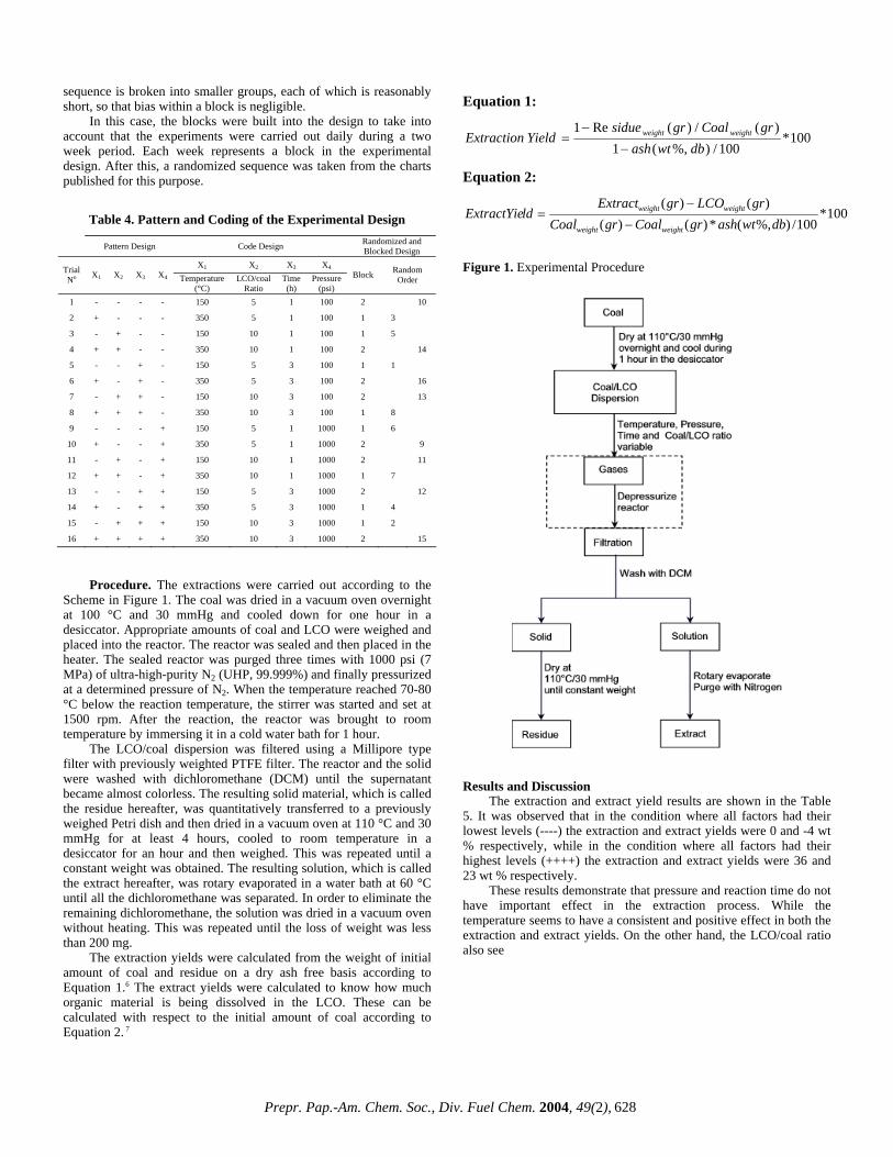
Procedure. The extractions were carried out according to the
Scheme in Figure 1. The coal was dried in a vacuum oven overnight at 100 °C and 30 mmHg and cooled down for one hour in a desiccator. Appropriate amounts of coal and LCO were weighed and placed into the reactor. The reactor was sealed and then placed in the heater. The sealed reactor was purged three times with 1000 psi (7 MPa) of ultra-high-purity N2 (UHP, 99.999%) and finally pressurized at a determined pressure of N2. When the temperature reached 70-80 °C below the reaction temperature, the stirrer was started and set at 1500 rpm. After the reaction, the reactor was brought to room temperature by immersing it in a cold water bath for 1 hour.
The LCO/coal dispersion was filtered using a Millipore type filter with previously weighted PTFE filter. The reactor and the solid were washed with dichloromethane (DCM) until the supernatant became almost colorless. The resulting solid material, which is called the residue hereafter, was quantitatively transferred to a previously weighed Petri dish and then dried in a vacuum oven at 110 °C and 30 mmHg for at least 4 hours, cooled to room temperature in a desiccator for an hour and then weighed. This was repeated until a constant weight was obtained. The resulting solution, which is called the extract hereafter, was rotary evaporated in a water bath at 60 °C until all the dichloromethane was separated. In order to eliminate the remaining dichloromethane, the solution was dried in a vacuum oven without heating. This was repeated until the loss of weight was less than 200 mg.
The extraction yields were calculated from the weight of initial amount of coal and residue on a dry ash free basis according to Equation 1.6 The extract yields were calculated to know how much organic material is being dissolved in the LCO. These can be calculated with respect to the initial amount of coal according to Equation 2. 7
Equation 1:
100*100/)%,(1
)(/)(Re1dbwtash
grCoalgrsidueYieldExtraction weightweight
−
−=
Equation 2:
100*100/)%,(*)()(
)()(dbwtashgrCoalgrCoal
grLCOgrExtractldExtractYie
weightweight
weightweight
−
−=
Figure 1. Experimental Procedure
Results and Discussion
The extraction and extract yield results are shown in the Table 5. It was observed that in the condition where all factors had their lowest levels (----) the extraction and extract yields were 0 and -4 wt % respectively, while in the condition where all factors had their highest levels (++++) the extraction and extract yields were 36 and 23 wt % respectively.
These results demonstrate that pressure and reaction time do not have important effect in the extraction process. While the temperature seems to have a consistent and positive effect in both the extraction and extract yields. On the other hand, the LCO/coal ratio also see
Prepr. Pap.-Am. Chem. Soc., Div. Fuel Chem. 2004, 49(2), 628
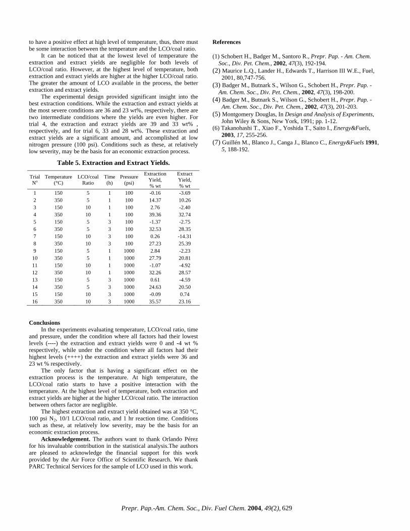
to have a positive effect at high level of temperature, thus, there must be some interaction between the temperature and the LCO/coal ratio.
It can be noticed that at the lowest level of temperature the extraction and extract yields are negligible for both levels of LCO/coal ratio. However, at the highest level of temperature, both extraction and extract yields are higher at the higher LCO/coal ratio. The greater the amount of LCO available in the process, the better extraction and extract yields.
The experimental design provided significant insight into the best extraction conditions. While the extraction and extract yields at the most severe conditions are 36 and 23 wt%, respectively, there are two intermediate conditions where the yields are even higher. For trial 4, the extraction and extract yields are 39 and 33 wt% , respectively, and for trial 6, 33 and 28 wt%. These extraction and extract yields are a significant amount, and accomplished at low nitrogen pressure (100 psi). Conditions such as these, at relatively low severity, may be the basis for an economic extraction process.
Table 5. Extraction and Extract Yields.
Trial No
Temperature (°C)
LCO/coal Ratio
Time (h)
Pressure (psi)
Extraction Yield, % wt
Extract Yield, % wt
1 150 5 1 100 -0.16 -3.69 2 350 5 1 100 14.37 10.26 3 150 10 1 100 2.76 -2.40 4 350 10 1 100 39.36 32.74 5 150 5 3 100 -1.37 -2.75 6 350 5 3 100 32.53 28.35 7 150 10 3 100 0.26 -14.31 8 350 10 3 100 27.23 25.39 9 150 5 1 1000 2.84 -2.23 10 350 5 1 1000 27.79 20.81 11 150 10 1 1000 -1.07 -4.92 12 350 10 1 1000 32.26 28.57 13 150 5 3 1000 0.61 -4.59 14 350 5 3 1000 24.63 20.50 15 150 10 3 1000 -0.09 0.74 16 350 10 3 1000 35.57 23.16
Conclusions In the experiments evaluating temperature, LCO/coal ratio, time
and pressure, under the condition where all factors had their lowest levels (----) the extraction and extract yields were 0 and -4 wt % respectively, while under the condition where all factors had their highest levels (++++) the extraction and extract yields were 36 and 23 wt % respectively.
The only factor that is having a significant effect on the extraction process is the temperature. At high temperature, the LCO/coal ratio starts to have a positive interaction with the temperature. At the highest level of temperature, both extraction and extract yields are higher at the higher LCO/coal ratio. The interaction between others factor are negligible.
The highest extraction and extract yield obtained was at 350 °C, 100 psi N2, 10/1 LCO/coal ratio, and 1 hr reaction time. Conditions such as these, at relatively low severity, may be the basis for an economic extraction process.
Acknowledgement. The authors want to thank Orlando Pérez for his invaluable contribution in the statistical analysis.The authors are pleased to acknowledge the financial support for this work provided by the Air Force Office of Scientific Research. We thank PARC Technical Services for the sample of LCO used in this work.
References
(1) Schobert H., Badger M., Santoro R., Prepr. Pap. - Am. Chem. Soc., Div. Pet. Chem., 2002, 47(3), 192-194.
(2) Maurice L.Q., Lander H., Edwards T., Harrison III W.E., Fuel, 2001, 80,747-756.
(3) Badger M., Butnark S., Wilson G., Schobert H., Prepr. Pap. - Am. Chem. Soc., Div. Pet. Chem., 2002, 47(3), 198-200.
(4) Badger M., Butnark S., Wilson G., Schobert H., Prepr. Pap. - Am. Chem. Soc., Div. Pet. Chem., 2002, 47(3), 201-203.
(5) Montgomery Douglas, In Design and Analysis of Experiments, John Wiley & Sons, New York, 1991; pp. 1-12.
(6) Takanohashi T., Xiao F., Yoshida T., Saito I., Energy&Fuels, 2003, 17, 255-256.
(7) Guillén M., Blanco J., Canga J., Blanco C., Energy&Fuels 1991, 5, 188-192.
Prepr. Pap.-Am. Chem. Soc., Div. Fuel Chem. 2004, 49(2), 629

CO-COKING OF HEAVY SOLUBLE FRACTIONS FROM COAL LIQUEFACTION AND PETROLEUM
VACUUM RESID: GAS, LIQUID AND SOLID DISTRIBUTION
Parvana Gafarova†*, Arif Hesenov*, Omer Gul†, Harold H. Schobert†
Oktay Erbatur*,
†The Energy Institute, The Pennsylvania State University, University Park, PA 16802
*Cukurova Universitesi, Fen-Edebiyat Fakultesi, Kimya Bolumu. 01330 Adana, Turkey
Introduction With the price of oil currently at an all time high, alternative fuels from coal have again come to the forefront. Direct catalytic coal liquefaction can be achieved technically, but has not been shown to be an economic process1. One attempt to render liquids from coal economically is to co-process coals and petroleum resids in delayed cokers already present in petroleum refineries. Not only could a liquid product be made, but it is also expected that high-grade carbon could be produced, thus contributing to the economic feasibility2,3,4. One of the problems with using raw coal in the coker is that it still contains mineral matter that is not desirable in coke. One way to eliminate the mineral matter is to pre-process the coal using direct catalytic hydrogenation. The present study focuses on catalytically hydrogenating coal and using the heavier liquid products in a delayed coking process. By using this process, the mineral matter is removed and the coal has begun to depolymerize. Use of this material as a feed to the coker could enhance the quality of the carbons produced from the coker because of the relatively high content of aromatics and polycondensed structures in the heavy oil fractions. Experimental
Material. Two coals were liquefied in this work. The first coal selected was a Pennsylvania coal from the Pittsburgh seam. This coal was selected from Penn State Coal Sample Bank and Database and was denoted as DECS 12. The second coal chosen was Cayirhan lignite from Beypazari, Turkey. This coal was selected because of its high liquefaction yield5,6. The ultimate analysis data are given in Table 1. Following catalytic hydrogenation of coals (details were given elsewhere5,6), oil fractions were removed by Soxhlet extraction using n-pentane and the heavier fraction was removed by extracting with tetrahydrofuran (THF). The material extracted by THF was called asphaltene + preasphaltene fraction and coded as ap. Specifically, the fraction obtained from Pittsburgh coal was coded as Pap and from Cayirhan as Cap. These materials, following removal of THF under reduced pressure were used in co-coking experiments.
Petroleum vacuum resid was received from the Aliaga-Izmir Petroleum Refinery of the Turkish Petroleum Refineries, Co. and has been coded as VR in this study. The elemental analysis of VR together with the elemental analysis of Pap and Cap are given in Table 2. NMR data for VR are also given in Table 3.
Coking experiments. All coking experiments were performed in a small tubing reactor system (25 mL volume). In a typical experiment, approximately 2.0 g of sample was charged into the reactor. After sealing the reactor, air inside the reactor was swept out by pressurizing (6.9 MPa) with nitrogen gas and then depressurizing the system. This procedure was repeated four more times and then the reactor was left at atmospheric pressure prior to coking treatment. While the reactor was under pressure, a leak test was performed. The reactor was then placed in a temperature controlled pre-heated
fluidized sand bath. The duration in all coking experiments was two hours.
Table 1. Analytical data of coals. DECS 12 Cayirhan
Rank hVAb Lignite Location USA-PA TURKEY-Beypazari Moisture 2.4 13.8
Ash 10.0 32.7 Elemental Analysis (wt % Dafa)
%C 83.3 73.1 %H 5.7 4.7 %N 1.4 1.9 %S 1.3 7.5 %Ob 8.4 12.8
a Daf: dry, ash-free. b Calculated from difference Following the two-hour treatment, the reactor was removed from the sand bath and quenched in a cold water bath. The weight of the tubing bomb reactor before and after discharging the gaseous products in a gas bag were recorded so as to determine the mass of gaseous products.
Table 2. Elemental analysis of petroleum vacuum resid and the heavy soluble fractions of hydrogenated coals, dafa.
VR Cap Pap %C 85.31 82.40 85.05 %H 10.17 9.20 7.58 %N 0.32 2.48 1.50 %S 4.70 2.88 0.53 %Ob 0.0 3.04 5.34 H/C 1.43 1.34 1.07
a Daf: dry, ash-free. b Calculated from difference: VR:Vacuum Resid, Cap: Cayirhan asphaltene + Preasphaltene, Pap: Pittsburgh asphaltene + preasphaltene.
Table 3. NMR results of petroleum vacuum resid. VR
Aromatic C 21.25 Aliphatic C 78.75 Aromatic H 6.00 Aliphatic H 94.23
fa 0.21 fa
H 0.060 The reactor was rinsed out with n-pentane into an extraction thimble and successively extracted in a Soxhlet apparatus with n-pentane and tetrahydrofuran. Oil and ap were the material solubilized in these two solvents, respectively. The solid part remaining in the ceramic thimble after THF extraction was denoted as the solid product. The mass of oil products was calculated by subtracting the total mass of gas+ap+solid from the mass of original reactant. The blends of VR:Pap and VR:Cap (with the mass ratios of 1:1, 1:2, and 2:1) and the individual VR, Pap, and Cap samples were coked as described above. Three different temperatures (450°C, 475°C and 500°C) were applied in the coking experiments. Coking of each type of sample was run in triplicate.
Prepr. Pap.-Am. Chem. Soc., Div. Fuel Chem. 2004, 49(2), 630
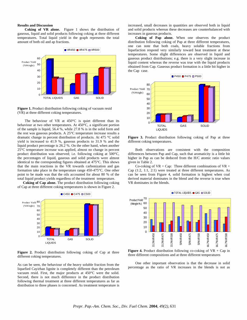
Results and Discussion Coking of VR alone. Figure 1 shows the distribution of
gaseous, liquid and solid products following coking at three different temperatures. Total liquid yield in the graph represents the total amount of both oil and ap fractions.
0
10
20
30
40
50
60Product Yield
(%Weight)
TOTAL LIQUIDS GAS SOLID
VR450 VR475 VR500
Figure 1. Product distribution following coking of vacuum resid (VR) at three different coking temperatures.
The behaviour of VR at 450°C is quiet different than its behaviour at two other temperatures. At 450°C, a significant portion of the sample is liquid, 56.4 %, while 27.8 % is in the solid form and the rest was gaseous products. A 25°C temperature increase results a dramatic change in percent distribution of products. At 475 °C solid yield is increased to 41.9 %, gaseous products to 31.9 % and the liquid product percentage is 26.2 %. On the other hand, when another 25°C temperature increase was applied, almost no change in percent product distribution was observed; i.e. following coking at 500°C, the percentages of liquid, gaseous and solid products were almost identical to the corresponding figures obtained at 475°C. This shows that the main reactions in the VR towards carbonization and gas formation take place in the temperature range 450-475°C. One other point to be made was that the oils accounted for about 80 % of the total liquid product yields regardless of the treatment temperature. Coking of Cap alone. The product distribution following coking of Cap at three different coking temperatures is shown in Figure 2.
0
10
2030
4050
6070
80Product Yield (%Weight)
TOTALLIQUIDS
GAS SOLID
C450 C475 C500
Figure 2. Product distribution following coking of Cap at three different coking temperatures. As can be seen, the behaviour of the heavy soluble fraction from the liquefied Cayirhan lignite is completely different than the petroleum vacuum resid. First, the major products at 450°C were the solid. Second, there is not much difference in the product distribution following thermal treatment at three different temperatures as far as distribution to three phases is concerned. As treatment temperature is
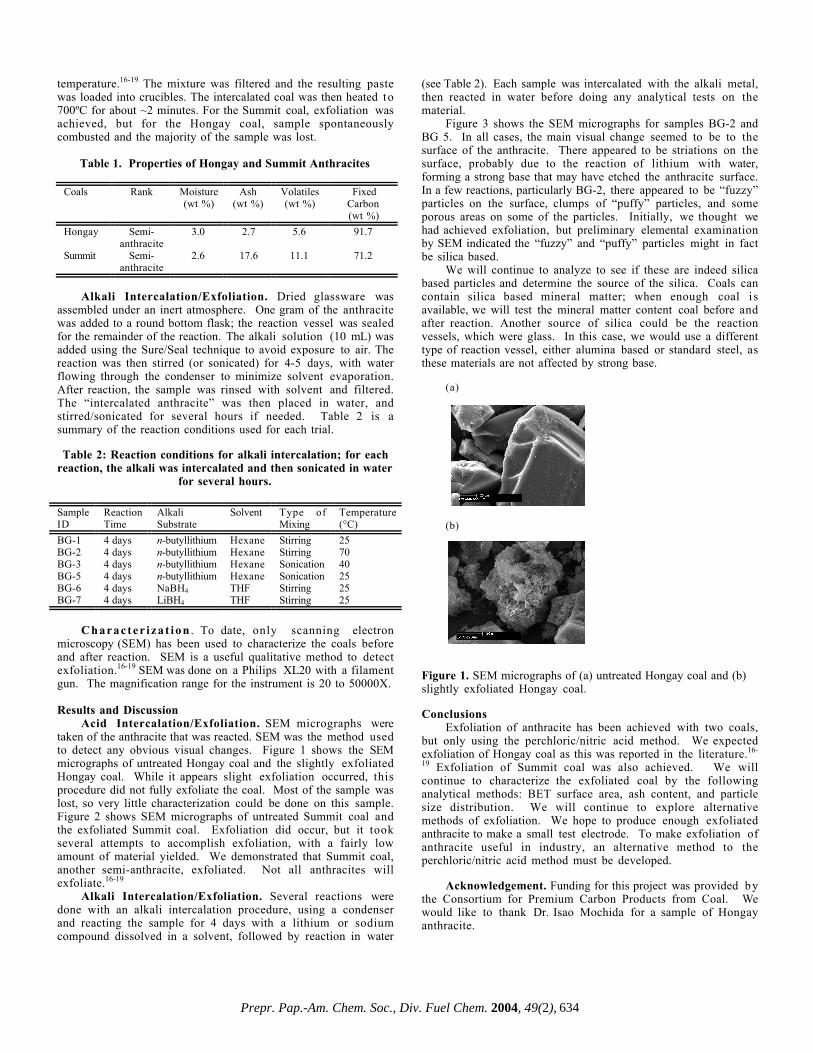
increased, small decreases in quantities are observed both in liquid and solid products whereas these decreases are counterbalanced with increases in gaseous products. Coking of Pap alone. When one observes the product distribution following coking of Pap at three different temperatures, one can note that both coals, heavy soluble fractions from liquefaction respond very similarly toward heat treatment at these temperatures. Some slight differences are observed in liquid and gaseous product distributions; e.g. there is a very slight increase in liquid content whereas the reverse was true with the liquid products obtained from Cap. Gaseous product formation is a little bit higher in the Cap case.
010
20304050
607080
Product Yield (%Weight)
TOTALLIQUIDS
GAS SOLID
P450 P475 P500
Figure 3. Product distribution following coking of Pap at three different coking temperatures.
Both observations are consistent with the composition differences between Pap and Cap, such that aromaticity is a little bit higher in Pap as can be deduced from the H/C atomic ratio values given in Table 2.
Co-coking of VR + Cap: Three different combinations of VR + Cap (1:2, 1:1, 2:1) were treated at three different temperatures. As can be seen from Figure 4, solid formation is highest when coal derived material dominates in the blend and the reverse is true when VR dominates in the blends.
010203040506070
33.3%
VR45
0
33.3%
VR47
5
33.3%
VR50
0
50%
VR45
0
50%
VR47
5
50%
VR50
0
66.7%
VR45
0
66.7%
VR47
5
66.7%
VR50
0
Product Yield (Weight % )
TOTAL LIQUIDS GAS SOLID
Figure 4. Product distribution following co-coking of VR + Cap in three different compositions and at three different temperatures
One other important observation is that the decrease in solid percentage as the ratio of VR increases in the blends is not as
Prepr. Pap.-Am. Chem. Soc., Div. Fuel Chem. 2004, 49(2), 631

dramatic as expected. As usual, higher treatment temperatures result in higher gas yields and this change is mainly counterbalanced with lower liquid yields. Co-coking of VR + Pap: The general trend of product distribution changes following coking of VR + Pap is similar to that of VR + Cap. The solid products ratios following the heat treatments at 450 °C and 475 °C are a little higher than the corresponding values obtained from VR + Cap, but at 500 °C the corresponding values are almost identical.
010203040506070
33.3
%V
R45
0
33.3
%V
R47
5
33.3
%V
R50
0
50%
VR
450
50%
VR
475
50%
VR
500
66.7
%V
R45
0
66.7
%V
R47
5
66.7
%V
R50
0
Product Yield (Weight %)
TOTAL LIQUIDS GAS SOLID
Figure 5. Product distribution following co-coking of VR + Pap in three different compositions and at three different temperatures
The relationship between gaseous and liquid products is almost the same for both VR + Pap and VR + Cap except in a few cases. When the liquid yield is compared with the corresponding liquid yield obtained from co-coking of original Pittsburgh coal with petroleum resid7, one can notice a higher yield in the former case. This is consistent with the differences of the original coal and its hydrogenated heavy soluble fraction, such that there are certainly more hydrogen-donating moieties in the latter case which can quench radicals and increase the formation of liquid products. Conclusions
This research is a work in progress. The best conclusions can be derived following investigating the compositions of liquid products and the structure of the carbons (solid products) that are formed under different conditions and with different blend compositions. Acknowledgement. This study has been supported by The Scientific and Technical Research Council of Turkey (TUBITAK). The authors are pleased to acknowledge the financial support for this work provided by the U. S. Air Force, Office of Scientific Research for portions of this work. HHS also acknowledges financial support from NATO for a collaborative visit to Çukurova University. References (1) Elliot, M.A.(Ed.), in “Chemistry of Coal Utilization
Secondary Supplementary Volume”, Wiley-Interscience Publication, New York, (1981).
(2) Olmstead, W.N., and Bearden, Jr., R., US Patent 5228981, July 20, 1993.
(3) Goval, S.K.; Kolstad, J.L.; Hauschildt, F.W.; Venardos, D.G.; Joval, C.L.M. US Patent 5286371, 1994.
(4) Moore, A.W.; Volk, H.F.; Merrow, J.K. US Patent 4061600, 1977.
(5) Gözmen, B.; Artok, L.; Erbatur, G.; Erbatur, O. Energy & Fuels 2002, 16, 1040-1047.
(6) Hesenov, A. Master Thesis, The Çukurova University, 2000. (7) Fickinger, A.E. Master Thesis, The Pennsylvania State
University, 2000.
Prepr. Pap.-Am. Chem. Soc., Div. Fuel Chem. 2004, 49(2), 632

EXFOLIATION OF ANTHRACITE: INDUSTRIALLYACHIEVABLE?
Caroline E. Burgess Clifford, Amy Beil, Erin Boland,and Laurie Grove
The Energy Institute, The Pennsylvania State University,University Park, PA 16802
IntroductionAnthracite is an abundant and inexpensive natural resource
that has not been fully exploited as a useful material. Historically,anthracite coal has been used as a slow-burning, high heatingvalue fuel that had a use for domestic heating and cooking as wellas industrial applications in iron smelting.1 More recently,anthracite has found a market as a water filter medium, but onlyanthracite obtained as-mined is used because of the difficulty(and expense) in grinding.
Anthracite is an intriguing feedstock for premium carbonmaterials. Most anthracites contain 92–98% carbon, virtually allof which is present as aromatic carbon in large polycyclic sheets.2
These sheets may contain thirty or more fused aromatic rings,3,4
resulting in extraordinary properties such as highly orderedcarbon that also exhibits a high ultra-microporosity pore volume.Exploiting one or more of these properties of anthracite toproduce value-added products offers the potential for developingnew markets for this resource.
Because anthracite has potential to be a valuable resource,research initiatives at PSU focused on exploiting the carbonproperties of anthracite. Several projects explored graphitizinganthracite for use as feedstock in electrodes.2,5-7 Pappano et al.examined the potential of anthracite as a filler for graphiteproduction, to determine if it behaved similarly to petroleumcoke (i.e., graphitization behavior, if material produced hasproperties suitable for industrial applications).2,5 Atria et al.examined the graphitization of several Pennsylvania anthracitesmixed with hydroaromatic hydrogen donor compounds (i.e.,dihydrophenanthrene). The hydrogen donor was used to helpbreak crosslinks in the anthracitic structure to enable the aromaticsheets to rearrange more easily into a graphitic structure.6,7 Atriaet al. suggested the hydrogen donor hydrogenated anthracite;therefore, another project explored the hydrogenation of smallparticles of anthracite for transforming coal into a pitch likematerial.8 Several projects explored making activated carbonsfrom anthracite.9-13 Most recently, anthracite was investigated as afeedstock in an aluminum-smelting anode.15 While the anodemade from anthracite exhibited superior properties in mostinstances, the anode did not meet industrial standards due themineral matter incorporated from coal. In all of these applications,a common factor was the anthracite was required to have a smallparticle size distribution and low mineral matter content,something not easily and inexpensively achieved byconventional methods.
Recently, the exfoliation of anthracite, a method to cause“flaking”, “expansion,” or “breaking apart” of the anthracite, wasexplored. The expectation is that exfoliation will open up thepores, reduce the particle size, and liberate mineral matter that i s“trapped” in the organic matter of coal that cannot be liberated byconventional methods.
Previous investigations have demonstrated anthraciteexfoliation.16-19 Perchloric acid and perchloric/nitric acidmixtures have been intercalated into the anthracite; the resultingintercalated carbons were thermally shocked in order to produce aprecursor for activated carbons.16-19
So, if anthracite can be exfoliated, why isn’t exfoliation ofanthracite occurring at the same level as other carbons? There area few problems that must be examined and solved to exfoliate thisextraordinary material and add value to it.
One major problem is the explosive nature of perchloricacid.20 Perchloric acid can be extremely explosive, and very smallquantities can cause extreme damage. For an industrial process tobe developed to exfoliate anthracite, a safer way must be found todo so. While perchloric/nitric acids are the only materials to dateto demonstrate anthracite exfoliation, there are severalcompounds that have been intercalated into graphites thatproduce exfoliation upon additional treatment.
In the literature, several methods have been reported forgraphite exfoliation.16-19,21,22 The most common method requiredintercalation of a mixture of concentrated nitric and sulfuric acids,followed by a thermal shock in an atmospheric muffle furnace tocause exfoliation.2 3 Reversible exfoliation of graphite wasachieved using bromine gas.2 3 Recently, graphite was exfoliatedusing potassium metal as the intercalate and reacting the resultingintercalated material with ethanol.2 4 Alkali metals, such as Li andNa, can be intercalated into carbon, but have not been shown toexfoliate upon reaction with water.25-28 However, molybdenum andtungsten sulfide exfoliation was accomplished using n-butyllithium as the substrate to intercalate lithium, followed byreaction in water to cause exfoliation.29-32 Very recently, graphitewas exfoliated using supercritical CO2 extraction.3 3
Even if exfoliation of anthracite can be achieved, safely, forwhat applications is it best suited? Exfoliated carbons are used toproduce a specialized gasket material. Anthracites were exfoliatedto produce a precursor for activated carbons.16-19 Historically,anthracites along with metallurgical coke and petroleum cokewere used as the main material in cathodes for aluminum and steelsmelting.34 Anthracites were attractive because of their abrasionresistance, but semi-graphite and other materials replacedanthracite because of superior electrical properties. The carbonmaterials used have evolved in recent years to using electricallycalcined anthracites, electrographite, semi-graphite, and a varietyof mixtures using these materials, mainly to reduce the electricalresistivity and increase the thermal conductivity of the electrode.Future electrodes will most likely include these carbons mixedwith hard metals in order to continue lowering the electricalresistivity and increasing the thermal conductivity.33 Anexfoliated anthracite may have improved electrical propertiescompared to a raw anthracite, while still maintaining its abrasionresistance. Exfoliation, which ix expected to open up the porestructure, will certainly improve the possibility of makinganthracite a medium to make activated carbons or an adsorptionmaterial.
The overall goal of the project is to develop a method ofexfoliation that would be less explosive than the nitric/perchloricacid method. The following describes the methods of exfoliationtested and the extent of exfoliation achieved.
ExperimentalMaterials. Two coals have been chosen to test in this
application. Proximate analysis information is provided in Table1. The rank of these coals is semi-anthracite. Hongay coal was thecoal shown to exfoliate in the literature, and is of semi-anthraciterank.16-19 The other coal was chosen because it was shown tographitize and was characterized extensively here at PSU.5
A c i d s w e r e p u r c h a s e d f r o m S i g m a -Aldrich. n-Butyllithium in hexane, LiBH4 in THF, and NaBH4 inTHF were also purchased from Sigma-Aldrich.
Acid Intercalation/Exfoliation. Coals were mixed with50/50 mixtures of perchloric/nitric acids for 2 hours at room
Prepr. Pap.-Am. Chem. Soc., Div. Fuel Chem. 2004, 49(2), 633
temperature.16-19 The mixture was filtered and the resulting pastewas loaded into crucibles. The intercalated coal was then heated to700ºC for about ~2 minutes. For the Summit coal, exfoliation wasachieved, but for the Hongay coal, sample spontaneouslycombusted and the majority of the sample was lost.
Table 1. Properties of Hongay and Summit Anthracites
Coals Rank Moisture(wt %)
Ash(wt %)
Volatiles(wt %)
FixedCarbon(wt %)
Hongay Semi-anthracite
3.0 2.7 5.6 91.7
Summit Semi-anthracite
2.6 17.6 11.1 71.2
Alkali Intercalation/Exfoliation. Dried glassware wasassembled under an inert atmosphere. One gram of the anthracitewas added to a round bottom flask; the reaction vessel was sealedfor the remainder of the reaction. The alkali solution (10 mL) wasadded using the Sure/Seal technique to avoid exposure to air. Thereaction was then stirred (or sonicated) for 4-5 days, with waterflowing through the condenser to minimize solvent evaporation.After reaction, the sample was rinsed with solvent and filtered.The “intercalated anthracite” was then placed in water, andstirred/sonicated for several hours if needed. Table 2 is asummary of the reaction conditions used for each trial.
Table 2: Reaction conditions for alkali intercalation; for eachreaction, the alkali was intercalated and then sonicated in water
for several hours.
SampleID
ReactionTime
AlkaliSubstrate
Solvent Type ofMixing
Temperature(°C)
BG-1 4 days n-butyllithium Hexane Stirring 25BG-2 4 days n-butyllithium Hexane Stirring 70BG-3 4 days n-butyllithium Hexane Sonication 40BG-5 4 days n-butyllithium Hexane Sonication 25BG-6 4 days NaBH4 THF Stirring 25BG-7 4 days LiBH4 THF Stirring 25
Character izat ion . To date, only scanning electronmicroscopy (SEM) has been used to characterize the coals beforeand after reaction. SEM is a useful qualitative method to detectexfoliation.16-19 SEM was done on a Philips XL20 with a filamentgun. The magnification range for the instrument is 20 to 50000X.
Results and DiscussionAcid Intercalation/Exfoliation. SEM micrographs were
taken of the anthracite that was reacted. SEM was the method usedto detect any obvious visual changes. Figure 1 shows the SEMmicrographs of untreated Hongay coal and the slightly exfoliatedHongay coal. While it appears slight exfoliation occurred, thisprocedure did not fully exfoliate the coal. Most of the sample waslost, so very little characterization could be done on this sample.Figure 2 shows SEM micrographs of untreated Summit coal andthe exfoliated Summit coal. Exfoliation did occur, but it tookseveral attempts to accomplish exfoliation, with a fairly lowamount of material yielded. We demonstrated that Summit coal,another semi-anthracite, exfoliated. Not all anthracites willexfoliate.16-19
Alkali Intercalation/Exfoliation. Several reactions weredone with an alkali intercalation procedure, using a condenserand reacting the sample for 4 days with a lithium or sodiumcompound dissolved in a solvent, followed by reaction in water
(see Table 2). Each sample was intercalated with the alkali metal,then reacted in water before doing any analytical tests on thematerial.
Figure 3 shows the SEM micrographs for samples BG-2 andBG 5. In all cases, the main visual change seemed to be to thesurface of the anthracite. There appeared to be striations on thesurface, probably due to the reaction of lithium with water,forming a strong base that may have etched the anthracite surface.In a few reactions, particularly BG-2, there appeared to be “fuzzy”particles on the surface, clumps of “puffy” particles, and someporous areas on some of the particles. Initially, we thought wehad achieved exfoliation, but preliminary elemental examinationby SEM indicated the “fuzzy” and “puffy” particles might in factbe silica based.
We will continue to analyze to see if these are indeed silicabased particles and determine the source of the silica. Coals cancontain silica based mineral matter; when enough coal i savailable, we will test the mineral matter content coal before andafter reaction. Another source of silica could be the reactionvessels, which were glass. In this case, we would use a differenttype of reaction vessel, either alumina based or standard steel, asthese materials are not affected by strong base.
(a)
(b)
Figure 1. SEM micrographs of (a) untreated Hongay coal and (b)slightly exfoliated Hongay coal.
ConclusionsExfoliation of anthracite has been achieved with two coals,
but only using the perchloric/nitric acid method. We expectedexfoliation of Hongay coal as this was reported in the literature.16-
19 Exfoliation of Summit coal was also achieved. We willcontinue to characterize the exfoliated coal by the followinganalytical methods: BET surface area, ash content, and particlesize distribution. We will continue to explore alternativemethods of exfoliation. We hope to produce enough exfoliatedanthracite to make a small test electrode. To make exfoliation ofanthracite useful in industry, an alternative method to theperchloric/nitric acid method must be developed.
Acknowledgement. Funding for this project was provided bythe Consortium for Premium Carbon Products from Coal. Wewould like to thank Dr. Isao Mochida for a sample of Hongayanthracite.
Prepr. Pap.-Am. Chem. Soc., Div. Fuel Chem. 2004, 49(2), 634

(a)
(b)
Figure 2. SEM micrographs of (a) untreated Summit coal and (b)exfoliated Summit coal.
(a)
(b)
Figure 3. SEM micrographs of Hongay anthracite after reaction (a)“puffy” particles and (b) striations.
References(1 ) Wallace, A.F.C., St. Clair: A Nineteenth Century Town’s
Experience with a Disaster Prone Industry. Alfred Knopf,New York, 1987.
(2 ) Pappano, P.J., Mathews, J.P., Schobert, H.H., Preprints,Amer. Chem. Soc. Div. Fuel Chem. 1999, 44, 567.
(3) Gerstein, B.C., Murphy, P.D., Ryan, L.M., In: Coal Structure.Academic Press, New York, 1982, Chapter 4.
( 4 ) van Krevelen, D.W., Coal: Typology–Chemistry–Physics–Constitution. Elsevier, Amsterdam, 1981.
( 5 ) Pappano, P.J., M.S. Thesis. The Pennsylvania StateUniversity, University Park, PA, 2001.
(6) Atria, J.V., M.S. Thesis. The Pennsylvania State University,University Park, PA, 1995.
( 7 ) Atria, J.V., Zeng, S., Rusinko, F., and Schobert, H.H.,Preprints, Amer. Chem. Soc. Div. Fuel Chem. 1994, 39, ??.
(8) Zengel, J.J., Schobert, H.H., Burgess, C.E., Andrésen, J.M.,Proc. 17th. Int. Pittsburgh Coal Conf., 2000, Paper 11-03.pdf(CD-ROM).
(9) Walker Jr., P.L., Almagro, A., Carbon, 1995, 33, 239.(10) Walker Jr., P.L., Imperial, G.R., Fuel, 1995, 74, 179.(11) Gergova, K., Eser, S., Schobert, H.H., Energy Fuels, 1 9 9 3 ,
7, 661.(12) Gergova, K., Eser, S., Schobert, H.H., Klimkiewicz, M.,
Brown, P.W., Fuel, 1995, 74, 1042.(13) Maroto-Valer, M.M., Andrésen, J.M., Schobert, H.H. Proc.
1st World Conf. Carbon, 2000, 1, 115.(14) Maroto-Valer, M.M., Taulbee, D., Schobert, H.H.. Preprints,
Amer. Chem. Soc. Div. Fuel Chem., 1999, 44, 101.(15) Badger, M., Mitchell, G., Katacen, O., Herman, N., Senger,
B., Adams, A., and Schobert, H.H., “Co-coking Process forAnodes for Aluminum Electrolysis,” DOE/CPCPC FinalReport, June, 2001.
(16) Pettijean, D., Klatt, M., Furdin, G., and Hérold, A., Carbon,1994, 32 (3), 461.
( 1 7 ) Albiniak, A., Furdin, G., Begin, D., Mareche, J.F.,Kaczmarczyk, J., and Broniek, E., Carbon, 1996 , 34 (11),1329.
(18) Furdin, G., Fuel, 1998, 77 (6) 479.(19) Daulan, C, Lyubchik, S.B., Rouzaud, J-N., and Béguin, F.,
Fuel, 1998, 77 (6), 495.(20) http://www.auburn.edu/administration/safety/crcperchloric.h
tml and references therein.(21) Toyoda, M., Katoh, H., and Inagaki, M., Carbon, 2001, 39,
2231-2237.(22) Frackowiak, E., Polish J. Chem., 1993, 67, 469-474.(23) Chung, D.D.L., J. Mat. Sci, 1987, 22 (12), 4190 and reference
therein.(24) Viculis, L.M., Mack, J.J., Kaner, R.B., Science, 2003 , 299,
5611.(25) Xheng, T., Xing, W., and Dahn, J.R., Carbon, 1 9 9 6 ,
34(12), 1501-1507.(26) Flandrois, S. and Simon, B., Carbon, 1999, 37, 165-180.(27) Sandi, G., Winans, RE and Carrado, KA, J. Electrochemical
Soc., 1996, 143 (5), L95-L98.(28) Mochida, I., Kim, Y-J., Ku, C-H., Yoon, S-H. and Korai, Y.,
Preprints, Amer. Chem. Soc. Div. Fuel Chem., 2 0 0 1 , 46(2),584.
(29) Dines, M.B., Mat. Res. Bull., 1975, 10, 287.(30) Murphy, D.W., Di Salvo, F.J., Hull, G.W., and Waszczak,
J.V., Inorg. Chem., 1976, 15 (1), 17.(31) Kosidowski, L. and Powell, A.V., Chem. Commun., 1 9 9 8 ,
2201.(32) Golub, A.S., Shumilova, I.B., Zubavichus, Y.V., Jahncke,
M., Süss-Fink, G, Danot, M, Novikov, Y.N., J. Mater.Chem., 1997, 7 (1), 163.
(33) Kaschak, D.M., Reynolds, III, R.A., Krassowski, D.W.,Ford, B.M., U.S. Patent, “Graphite intercalation andexfoliation process,” #20040033189, February 19, 2004.
(34) Sørlie, M. and Øye, H.A., Cathodes in aluminum electrolysis,Aluminum-Verlag GmbH: Dusseldorf, 1994, pp. 1-20.
Prepr. Pap.-Am. Chem. Soc., Div. Fuel Chem. 2004, 49(2), 635

COMPARISON OF ALTERNATIVE COAL DERIVED BINDER PITCHES FOR CARBON MATERIALS
Uthaiporn Suriyapraphadilok, Colin Jennis-McGroarty and
John M. Andresen
The Energy Institute, Pennsylvania State University
407 Academic Activities Bldg., University Park, PA 16802 Introduction
Carbon anodes are manufactured from calcined petroleum coke, butt fillers and coal tar pitch. Since the demand of the coal tar pitch in the aluminum industry accounts for about 75% of the pitch market [1] and the production of coal tars is rapidly decreasing in the United States as well as throughout the world [2], the development of alternative binders were considered in this work. Coal tar binder pitches are traditionally obtained from coal tars that are the by-product of bituminous coal coking process used to make coke for blast furnaces in iron production. During the manufacturing of carbon anodes coal tar pitch is mixed with calcined petroleum coke, where petroleum coke is the by-product from the delayed coker in a refinery. Remaining parts of spent anodes from the aluminum production, namely butts, are also crushed and used as filler [3].
This work is focused on the development of alternative binders from various sources of pitches, namely, petroleum pitch (PP), coal-extracted pitch (WVU), and gasification pitch (GP). Petroleum pitch is a residue produced from heat-treatment and distillation of petroleum fractions. A production of coal-extracted pitch involves a prehydrogenation of coal followed by extraction using a dipolar solvent. Gasification pitches are distilled by-product tars produced from the coal gasification process. Each alternative pitch was mixed with a standard coal tar pitch (SCTP) at various mixtures and laboratory-scale test anodes were formed and studied. Experimental Materials. Four types of pitch were used in this study: two standard coal tar binder pitches (SCTP1 and -2), a petroleum pitch (PP), a coal-extraction pitch (WVU5), and a gasification pitch (GP1). The properties of each pitch are summarized in Table 1. Petroleum coke and recycled anode butts were crushed and aggregated into three different sizes: (i) Fines: >200 Tyler mesh size; (ii) Intermediate: 60-200 Tyler mesh size; and (iii) Coarse: <60 Tyler mesh size
Table 1. Properties of pitches Property SCTP1 SCTP2 PP WVU5 GP1
Softening Point (°C) 112.5 111.9 111.9 112.2
115 Quinoline Insol.
(wt%) 13.6 15.9 0.1 N.A.
<0.1
Toluene Insol. (wt%) 27.8 30.9 3.2 N.A.
N.A. Coking Value (wt%) N.A. 57.9 47 50.3 N.A. Ash Content (wt%) N.A. 0.29 0.08 0.2 N.A. Specific Gravity @
25°C N.A. 1.34 1.246 1.25
N.A. Compositions. All experimental-scale anodes in this work were made using the following compositions:
Pitch:Butt:Coke = 22:29:49 Fine:Intermediate:Coarse = 40:35:25
Mixing and Forming. The aggregate fillers and binders, which weighed about 15 grams in total, were mixed at about 50°C above
the softening point of the pitch mixture. The CARVER cylindrical mold with an inside diameter of 28.58 mm was preheated to about 10°C above the softening point of the pitch mixture. The hot mix was placed into the mold and rapidly pressed at 9,000 psi for 2.5 minutes. The final green anode was cylindrical in shape with typically 28.60 mm. in diameter and 13.00-14.00 mm in height. Baking. The green anodes were baked with a low heating rate to about 1075°C over a period of 5-6 days prior to cooling. The temperature profile was 25°C/hr from 25°C to 125°C; 3.5°C/hr from 125 to 575°C; 100°C/hr from 575 to 1075°C; hold at the temperatures between 950 and 1075°C for 6 hours; and cool down in the furnace to room temperature. Measured Properties. The green and baked anodes were weighed to the nearest 0.001 gram and their dimensions were measured by a caliper to the nearest 0.01 millimeter. The apparent densities of both green and baked anodes were calculated by a ratio of mass and volume. The amount of pitch loss after baking was calculated by assuming that all the weight loss was resulting from the pyrolysis of pitch. Finally, the volume change of the baked anodes relative to the green ones was calculated. Results and Discussion Each type of pitch was mixed with the standard coal tar pitch (SCTP) at various percentages while maintaining the total pitch content of 22 wt% for the anode aggregate. Figures 1-3 show the apparent and baked densities of the green and baked anodes, %pitch loss and %volume change of the experimental-scale anodes of the SCTP2+PP, SCTP2+WVU5 and SCTP1+GP1 mixtures, respectively. The addition of PP gives an improvement in apparent densities for both green and baked anodes (Figure 1(a)). For PP the green apparent density increases from 1.719 g/cm3 for the SCTP2 only to 1.736 g/cm3 for the PP only, while the baked apparent density increases from 1.542 g/cm3 for the SCTP2 only to 1.561 g/cm3 for the PP only. However, these trends do not keep up for the addition of WVU5 and GP1. The addition of WVU5 gave slightly poorer densities of the green anode and the baked anodes (Figure 2(a)) and . The green apparent density of the SCTP2+WVU5 decreases from 1.719 g/cm3 for the SCTP2 only to 1.703 g/cm3 for the WVU5 only, while the baked apparent density decreases from 1.542 g/cm3 for the SCTP2 only to 1.491 g/cm3 for the WVU-5 only. For GP1, the green apparent density of the SCTP1+GP1 increases from 1.71 g/cm3 for the SCTP1 only to 1.73 g/cm3 for the GP1 only, while the baked apparent density decreases from 1.60 g/cm3 for the SCTP1 only to 1.54 g/cm3 for the GP1 only. The main factor for the reduction in baked density is due to the increased loss of binder during baking as shown in Figures 1(b), 2(b) and 3(b). The pitch loss is defined as a reduction in anode weight over initial pitch content (22%) since the weight loss of the coke material can be neglected. The addition of GP1 to the SCTP1 tends to give the highest pitch loss among all three mixtures (Figure 3(b)), while the addition of PP gives a slightly increase in pitch loss compared to the SCTP2 only (Figure 1(b)). Also, for all SCTP + alternative pitch studied here, the addition of the alternative pitch gives a lower volume change of the baked anodes compared to the baked anodes with SCTP only as shown in Figures 1(c), 2(c), and 3(c).
Of all pitch mixtures studied here, the addition of an alternative pitch shows quite similar trends, i.e. SCTP gives a lower pitch loss and higher volume change compared to the pure alternative pitches. Among all three alternative pitches, the addition of WVU5 and GP1 shows poorer properties of the anodes among all three mixtures, i.e. high pitch loss and low baked densities, while the addition of PP shows little impact on the properties of the anodes for most SCTP-PP compositions. The addition of GP1 and WVU5 also gives
Prepr. Pap.-Am. Chem. Soc., Div. Fuel Chem. 2004, 49(2), 636
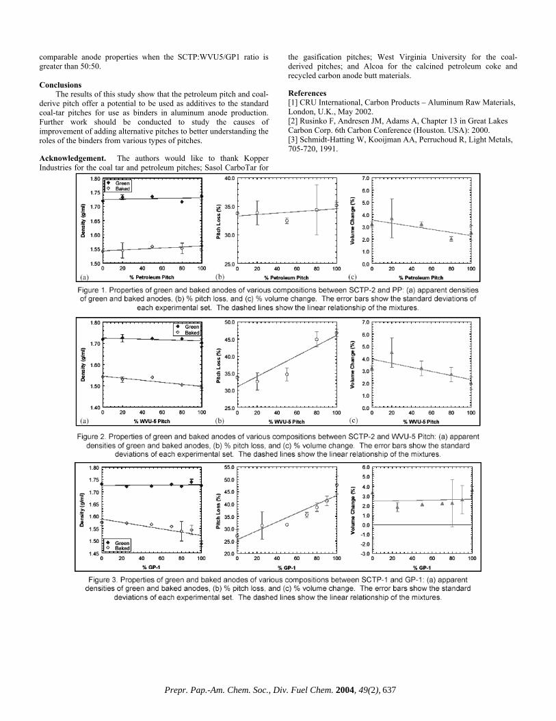
comparable anode properties when the SCTP:WVU5/GP1 ratio is greater than 50:50.
Conclusions
The results of this study show that the petroleum pitch and coal-derive pitch offer a potential to be used as additives to the standard coal-tar pitches for use as binders in aluminum anode production. Further work should be conducted to study the causes of improvement of adding alternative pitches to better understanding the roles of the binders from various types of pitches. Acknowledgement. The authors would like to thank Kopper Industries for the coal tar and petroleum pitches; Sasol CarboTar for
the gasification pitches; West Virginia University for the coal-derived pitches; and Alcoa for the calcined petroleum coke and recycled carbon anode butt materials. References [1] CRU International, Carbon Products – Aluminum Raw Materials, London, U.K., May 2002. [2] Rusinko F, Andresen JM, Adams A, Chapter 13 in Great Lakes Carbon Corp. 6th Carbon Conference (Houston. USA): 2000. [3] Schmidt-Hatting W, Kooijman AA, Perruchoud R, Light Metals, 705-720, 1991.
Prepr. Pap.-Am. Chem. Soc., Div. Fuel Chem. 2004, 49(2), 637
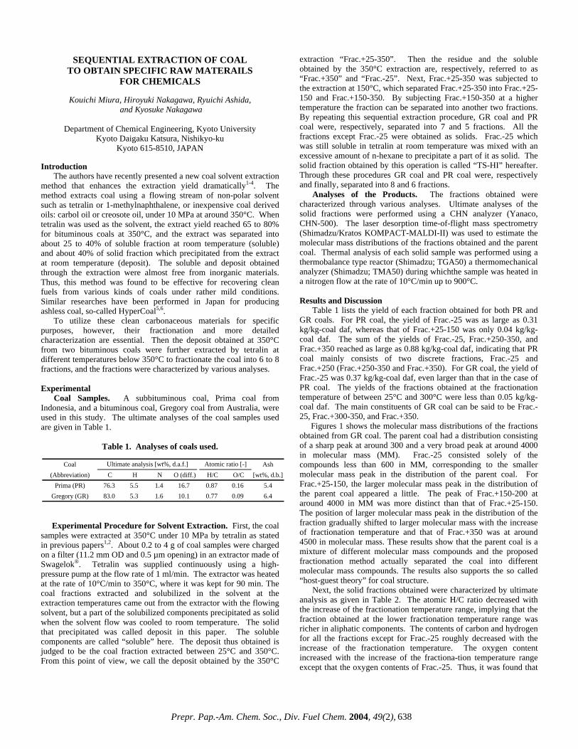
SEQUENTIAL EXTRACTION OF COAL TO OBTAIN SPECIFIC RAW MATERAILS
FOR CHEMICALS
Kouichi Miura, Hiroyuki Nakagawa, Ryuichi Ashida, and Kyosuke Nakagawa
Department of Chemical Engineering, Kyoto University
Kyoto Daigaku Katsura, Nishikyo-ku Kyoto 615-8510, JAPAN
Introduction
The authors have recently presented a new coal solvent extraction method that enhances the extraction yield dramatically1-4. The method extracts coal using a flowing stream of non-polar solvent such as tetralin or 1-methylnaphthalene, or inexpensive coal derived oils: carbol oil or creosote oil, under 10 MPa at around 350°C. When tetralin was used as the solvent, the extract yield reached 65 to 80% for bituminous coals at 350°C, and the extract was separated into about 25 to 40% of soluble fraction at room temperature (soluble) and about 40% of solid fraction which precipitated from the extract at room temperature (deposit). The soluble and deposit obtained through the extraction were almost free from inorganic materials. Thus, this method was found to be effective for recovering clean fuels from various kinds of coals under rather mild conditions. Similar researches have been performed in Japan for producing ashless coal, so-called HyperCoal5,6.
To utilize these clean carbonaceous materials for specific purposes, however, their fractionation and more detailed characterization are essential. Then the deposit obtained at 350°C from two bituminous coals were further extracted by tetralin at different temperatures below 350°C to fractionate the coal into 6 to 8 fractions, and the fractions were characterized by various analyses. Experimental Coal Samples. A subbituminous coal, Prima coal from Indonesia, and a bituminous coal, Gregory coal from Australia, were used in this study. The ultimate analyses of the coal samples used are given in Table 1.
Table 1. Analyses of coals used.
Experimental Procedure for Solvent Extraction. First, the coal
samples were extracted at 350°C under 10 MPa by tetralin as stated in previous papers1,2. About 0.2 to 4 g of coal samples were charged on a filter (11.2 mm OD and 0.5 µm opening) in an extractor made of Swagelok®. Tetralin was supplied continuously using a high-pressure pump at the flow rate of 1 ml/min. The extractor was heated at the rate of 10°C/min to 350°C, where it was kept for 90 min. The coal fractions extracted and solubilized in the solvent at the extraction temperatures came out from the extractor with the flowing solvent, but a part of the solubilized components precipitated as solid when the solvent flow was cooled to room temperature. The solid that precipitated was called deposit in this paper. The soluble components are called “soluble” here. The deposit thus obtained is judged to be the coal fraction extracted between 25°C and 350°C. From this point of view, we call the deposit obtained by the 350°C
extraction “Frac.+25-350”. Then the residue and the soluble obtained by the 350°C extraction are, respectively, referred to as “Frac.+350” and “Frac.-25”. Next, Frac.+25-350 was subjected to the extraction at 150°C, which separated Frac.+25-350 into Frac.+25-150 and Frac.+150-350. By subjecting Frac.+150-350 at a higher temperature the fraction can be separated into another two fractions. By repeating this sequential extraction procedure, GR coal and PR coal were, respectively, separated into 7 and 5 fractions. All the fractions except Frac.-25 were obtained as solids. Frac.-25 which was still soluble in tetralin at room temperature was mixed with an excessive amount of n-hexane to precipitate a part of it as solid. The solid fraction obtained by this operation is called “TS-HI” hereafter. Through these procedures GR coal and PR coal were, respectively and finally, separated into 8 and 6 fractions.
Analyses of the Products. The fractions obtained were characterized through various analyses. Ultimate analyses of the solid fractions were performed using a CHN analyzer (Yanaco, CHN-500). The laser desorption time-of-flight mass spectrometry (Shimadzu/Kratos KOMPACT-MALDI-II) was used to estimate the molecular mass distributions of the fractions obtained and the parent coal. Thermal analysis of each solid sample was performed using a thermobalance type reactor (Shimadzu; TGA50) a thermomechanical analyzer (Shimadzu; TMA50) during whichthe sample was heated in a nitrogen flow at the rate of 10°C/min up to 900°C.
Results and Discussion
Table 1 lists the yield of each fraction obtained for both PR and GR coals. For PR coal, the yield of Frac.-25 was as large as 0.31 kg/kg-coal daf, whereas that of Frac.+25-150 was only 0.04 kg/kg-coal daf. The sum of the yields of Frac.-25, Frac.+250-350, and Frac.+350 reached as large as 0.88 kg/kg-coal daf, indicating that PR coal mainly consists of two discrete fractions, Frac.-25 and Frac.+250 (Frac.+250-350 and Frac.+350). For GR coal, the yield of Frac.-25 was 0.37 kg/kg-coal daf, even larger than that in the case of PR coal. The yields of the fractions obtained at the fractionation temperature of between 25°C and 300°C were less than 0.05 kg/kg-coal daf. The main constituents of GR coal can be said to be Frac.-25, Frac.+300-350, and Frac.+350.
Figures 1 shows the molecular mass distributions of the fractions obtained from GR coal. The parent coal had a distribution consisting of a sharp peak at around 300 and a very broad peak at around 4000 in molecular mass (MM). Frac.-25 consisted solely of the compounds less than 600 in MM, corresponding to the smaller molecular mass peak in the distribution of the parent coal. For Frac.+25-150, the larger molecular mass peak in the distribution of the parent coal appeared a little. The peak of Frac.+150-200 at around 4000 in MM was more distinct than that of Frac.+25-150. The position of larger molecular mass peak in the distribution of the fraction gradually shifted to larger molecular mass with the increase of fractionation temperature and that of Frac.+350 was at around 4500 in molecular mass. These results show that the parent coal is a mixture of different molecular mass compounds and the proposed fractionation method actually separated the coal into different molecular mass compounds. The results also supports the so called “host-guest theory” for coal structure.
Coal Ash(Abbreviation) C H N O (diff.) H/C O/C [wt%, d.b.]
Prima (PR) 76.3 5.5 1.4 16.7 0.87 0.16 5.4Gregory (GR) 83.0 5.3 1.6 10.1 0.77 0.09 6.4
Ultimate analysis [wt%, d.a.f.] Atomic ratio [-]
Next, the solid fractions obtained were characterized by ultimate analysis as given in Table 2. The atomic H/C ratio decreased with the increase of the fractionation temperature range, implying that the fraction obtained at the lower fractionation temperature range was richer in aliphatic components. The contents of carbon and hydrogen for all the fractions except for Frac.-25 roughly decreased with the increase of the fractionation temperature. The oxygen content increased with the increase of the fractiona-tion temperature range except that the oxygen contents of Frac.-25. Thus, it was found that
Prepr. Pap.-Am. Chem. Soc., Div. Fuel Chem. 2004, 49(2), 638

this method could separate coal into the fractions which have different elemental compositions and so might have different chemical structures. Most of ash in the parent coal was retained in Frac.+350 as reported in the previous papers 1-4. The other fractions, containing less than 0.6wt% ash for PR coal or less than 1.4wt% ash for GR coal, were rather clean, suggesting that these fractions could be utilized as starting materials of various carbon materials. The solubility parameter, δ, is calculated by using Painter’s correlation7 given for each fraction for GR coal as reference. It increased with increasing fractionation temperature as expected.
Figure 2 shows TG curve for each fraction for GR coal. The volatile yield decreased with the increase of the fractionation temperature range and the volatile yields of the Frac.-25 (TS-HI) and Frac.+25-150 were larger than the yield of the parent coal. Figure 3 shows thermomechanical analysis curve of each fraction obtained from GR coal. The softening temperatures can be estimated from these curves to be 240ºC for Frac.-25, 268ºC for Frac.+25-150, 318ºC for Frac.+150-200, and 349ºC for Frac.+200-250. The softening temperature of the fraction increased with the increase of the fractionation temperature, which means that coal was well fractionated in terms of fusibility by the proposed method. curves of Frac.-25 and Frac.+25-150 were rather close to the displacement curve of a naphthalene-based anisotropic pitch synthesized for producing high per-formance carbon mate-rials. This result suggests a possibility of uti-lizing the fraction as a feedstock of high performance carbon materials.
Acknowledgement. The supports from the Ministry of Education of Japan (Grant No.737) and Kobe Steel, Ltd. are acknowledged.
References 1. Miura, K.; Shimada, M.; Mae, K., 15th Pittsburgh Int. Coal Conf.,
Paper No.30-1, Pittsburgh, 1998. 2. Miura, K.; Shimada, M.; Mae, K.; Huan, Y.S., Fuel, 2001. 80,
1573-1582. 3. Miura, K.; Mae, K.; Shindo, H.; Ashida, R.; Ihara, T., J. Chem.
Eng. Japan, 2003, 36, 742-750. 4. Miura, K.; Nakagawa, H.; Ashida, R.; Ihara, T., Fuel, 2004, 83,
733-738. 5. Okuyama, N.; Inoue, Y.; Shigehisa, T.; Shinozaki, S., Proc. 39th
Conf. Coal Science (in Japanese), p.93, 2002. 6. Yoshida, T.; Takanohashi, T.; Sakanishi, K.; Saito, I.; Fujita, M.;
Mashimo, K., Fuel, 2002, 81, 1463-1469. 7. Painter, P.C.; Graf, J.; Michael, M.C., EnergyFuels, 1990, 4, 379-
384.
600050004000300020001000Mass/charge
Frac.+350
Frac.+300-350
Frac.+250-300
Frac.+200-250
Frac.+150-200
Frac.+25-150
Frac.-25
GR parent coal
Inte
nsity
[a.u
.]
600050004000300020001000Mass/charge
Frac.+350
Frac.+300-350
Frac.+250-300
Frac.+200-250
Frac.+150-200
Frac.+25-150
Frac.-25
GR parent coal
Inte
nsity
[a.u
.]
Figure 1. Molecilara mass distribu- tion of each fraction for GR coal.
1.0
0.8
0.6
0.4
0.2
0
Rel
ativ
e w
eigh
t [kg
/kg-
daf]
800600400200Temperature [°C]
Frac.+25-150
Frac.+150-200
Frac.+300-350
GR
Parent coal
Frac.-350
Frac.+350
Frac.-25 (TS-HI)
a = 10°C/min
Figure 2. TG curve of each fraction for GR coal.
-1.0
-0.8
-0.6
-0.4
-0.2
0.0
Nor
mal
ized
dis
plac
emen
t [-]
500400300200100Temperature [°C]
Parent coal
Frac.+300-350Frac.+250-300
Frac.+200-250
Frac.+150-200
Frac.+25-150
Frac.-350
Frac.+350Frac.-25 (TS-HI)
(b) GR
a = 10°C/min
Figure 3. TMA curve of each fraction for GR coal.
Prepr. Pap.-Am. Chem. Soc., Div. Fuel Chem. 2004, 49(2), 639

Yield δ Ash[kg/kg-coal daf] [MPa**0.5] C H N O (diff.) H/C O/C [wt%, d.b.]
Frac.-25 (calc.) 0.31 74.7 6.4 0.3 18.6 1.02 0.19 -Frac.+25-150 0.04 80.9 6.2 2.1 10.8 0.92 0.10 0.6Frac.+150-250 0.06 80.2 5.7 2.0 12.0 0.85 0.11 0.3Frac.+250-350 0.21 80.4 5.4 2.1 12.0 0.81 0.11 0.3Frac.+350 0.36 78.9 4.9 1.9 14.3 0.74 0.14 8.8Parent coal 76.3 5.5 1.4 16.7 0.86 0.16 5.4Frac.-25 (calc.) 0.37 22.46 81.1 5.4 0.8 12.7 0.80 0.12 0.2Frac.+25-150 0.01 23.21 85.4 5.9 2.1 6.5 0.82 0.06 0.3Frac.+150-200 0.05 24.44 84.5 5.5 2.1 7.9 0.78 0.07 0.6Frac.+200-250 0.02 24.42 84.1 5.5 2.2 8.2 0.78 0.07 1.2Frac.+250-300 0.01 25.19 83.5 5.3 2.0 9.2 0.75 0.08 1.1Frac.+300-350 0.10 25.57 84.0 5.1 2.0 8.9 0.73 0.08 1.4Frac.+350 0.44 25.46 84.0 5.2 2.1 8.7 0.74 0.08 12.9Parent coal 25.06 83.0 5.3 1.6 10.1 0.76 0.09 6.4
PR
GR
Table 2. Yield, ultimate analysis, and solubiliuty parameter of each fraction
Coal Fraction Ultimate analysis [wt%, d.a.f.] Atomic ratio [-]
Prepr. Pap.-Am. Chem. Soc., Div. Fuel Chem. 2004, 49(2), 640

DISTRIBUTION OF POLYCYCLIC AROMATIC HYDROCARBONS (PAHS) AND INORGANIC TRACE
ELEMENTS IN LIME SPRAY DRYER (LSD) ASH
Ping Sun, Panuwat Taerakul, Linda K. Weavers, Harold W. Walker, and Danold W Golightly
Department of Civil and Environmental Engineering
and Geodetic Science, The Ohio State University 470 Hitchcock Hall 2070 Neil Avenue
Columbus, OH, 43210 Introduction
Flue gas desulfurization (FGD) by-product is a residual material from processes used to remove sulfur dioxide from flue gas in coal combustion processes. Approximately 26 million metric tons of FGD by-products are produced in the United States every year with more than 18 million metric tons (72% of total production) sent to landfills1,2. To minimize landfilling, studies have been conducted to examine applications of FGD by-product, such as in construction, agriculture and mine reclamation3,4. Prior to reuse, FGD by-product must be characterized for potential environmental hazards.
The lime spray dryer (LSD) system is the most common dry FGD technique1. A fine spray of slaked lime (Ca(OH)2) is injected into the scrubber, reacting with sulfur oxides resulting in the formation of calcium sulfate or calcium sulfite. Moisture in the reacted lime is lost due to heat from the flue gas. The resulting dry calcium sulfite/sulfate mixture, along with fly ash, is later collected as “LSD ash” by electrostatic precipitation or a baghouse1.
PAHs are a class of organic compounds that are persistent in the environment5. Many PAHs are carcinogenic and/or mutagenic6. A major source of PAHs in the environment is from fossil fuel combustion processes (i.e., coal burning) 7 . Our previous work showed that PAH concentrations were related to organic carbon content in the LSD ash8. Studies on PAHs in fly ash samples also show that PAHs are mainly associated with carbonaceous materials, which was believed to be the dominant factor for adsorption of PAHs in fly ash9. High carbon content material such as unburned carbon has also been suggested to be an effective material for capturing volatile trace elements, such as As, Se and Hg in flue gas10.
The purpose of this study was to examine the hypothesis that PAHs and trace inorganic elements mainly partition to carbonaceous material in LSD ash. If this hypothesis is true, the concentration of PAHs and trace inorganic elements in LSD ash in the absence of carbonaceous material will be much lower and the environmental impact of LSD ash utilization will be correspondingly less.
Experimental
LSD ash sampling. LSD ash was sampled at boiler #8 at the McCracken Power Plant on The Ohio State University. Multiple grab samples were collected and subsequently stored at 4oC until the chemical measurements were performed.
LSD ash fractionation. A 140 mesh (106 µm) sieve was used to separate LSD ash samples into two fractions: >140 mesh and <140 mesh. Of the initial 10 g LSD ash sample, 1.5 g was retained on the top of 140 mesh sieve. This >140 mesh fraction was further separated using a lithiumheteropolytungstate (LST) solution with a specific gravity of 1.84 g/mL. 0.5 g of >140 mesh sample and 10 mL of LST solution were mixed in a glass centrifuge tube. The unburned carbon floated to the top of the centrifuge tube. The solids were decanted, collected on filter paper, and washed with 50 mL high purity water to remove the LST solution. Unburned carbon samples were then dried
in an oven at 60 ºC for 12 hours. Organic carbon content was measured as described elsewhere8.
PAH analysis. An ultrasonic probe with a 1.90 cm diameter titanium tip (Fisher Scientific), operating at 20 kHz, was used for ultrasonic extraction. In all experiments, the output control knob was set at 10 (full power) and pulse mode (energy on 50% of time and off 50% of time). Effective sonication time was 1.5 minutes. A 20g sample was weighed into the beaker and mixed with 100 mL toluene and spiked with a 16 PAH standard containing 1 µg of each PAH. The end of the probe tip was located 1.3 cm below the surface of the liquid but above the solid. After extraction, the extract was decanted, filtered through a Whatman GF/B filter in a Buchner funnel and then collected in a filtration flask. The ultrasonic extraction was repeated twice with two additional 100 mL aliquots of solvent. After the third extraction, all extracts were poured into the Buchner funnel and rinsed with 20~30 mL solvent. The collected extract was then condensed using a Kuderna-Danish (K-D) concentrator to less than 10 mL. High purity nitrogen gas (Praxair) was used to further blowdown the extract to 1mL for GC/MS analysis. Details of the GC/MS analysis method are stated elsewhere8. Twenty grams of LSD by-product sample without adding the PAH standard were also extracted by ultrasound (this is not a blank). Duplicate experiments were conducted to ensure reproducibility.
Inorganic analysis. Inorganic analyses were accomplished by digesting approximately 150 to 300 mg samples by a microwave heating method with a combination of 10 mL deionized water, 6-mL nitric acid, 2 mL hydrochloric acid, and 2 mL hydrofluoric acid. This was followed by a second microwave heating with 20 mL boric acid.
A Vista Pro simultaneous inductively coupled plasma optical emission spectrometer system was used to determine selected metals in sample solutions. As and Se were analyzed by a SpectrAA 880Z Zeeman graphite furnace atomic absorption (AA) spectrometer and Hg was determined by AA with a vapor generation accessory. All analyses included controls such as duplicates, blanks, and check standards for every fifteen samples or less.
Results and Discussion
Fractionation and characterization of LSD ash. Inorganic element concentration and organic carbon content of LSD ash on a weight percent for separated fractions are listed in Table 1. The results show that the organic carbon content of >140 mesh fraction was much higher than the parent LSD ash sample (e.g. 48.5% vs 7.0%), which indicates that sieving effectively enriched the carbonaceous fraction above the 140 mesh sieve. Compared to the >140 mesh fraction and parent LSD ash sample, the <140 mesh fraction had a much lower organic carbon content of 2.0%. Similar to organic carbon, the distribution of Al, Fe and Si concentrations was larger in the >140 mesh fraction which indicates enrichment of fly ash constituents. On the other hand, the Ca and S concentrations in the >140 mesh were much less than in the parent LSD ash, and the <140 mesh fraction was enriched in Ca. Results in Table 1 also show that unburned carbon was separated from the >140 mesh fraction using LST solution. The LST extract had an even higher carbon content (88.7%) compared to 48.5% for the >140 mesh fraction.
PAH Distribution in LSD ash. The concentration of total PAHs in parent LSD ash and the separated >140 mesh and <140 mesh fractions are listed in Table 2. The total PAH concentration was 78.7 µg/kg in >140 mesh fraction, which was higher than 14.1 µg/kg in parent LSD ash and 18.9 µg/kg in <140 mesh fraction. Since the mass percentage of the >140 mesh fraction was about 15% of the total LSD ash, the high concentration of PAHs in carbon-enriched fraction demonstrates that PAHs were mainly associated with the carbonaceous material in LSD ash.
Prepr. Pap.-Am. Chem. Soc., Div. Fuel Chem. 2004, 49(2), 641

Table 1. Major Constituents in Different Fractions >140 mesh Elements
/Parameter
Unit
Parent
LSD Ash
<140 mesh
>140 mesh >1.84
g/mL <1.84 g/mL
Ca % 30.9 30.5 11.7 15.2 0.4 S % 13.7 13.4 3.6 6.0 0.2 Si % 4.2 1.9 3.8 9.7 6.8 Fe % 2.6 2.1 6.3 10.5 1.2 Al % 1.6 1.0 2.8 4.9 2.4
Org.C % 7.0 2.0 48.5 26.2 88.7 Spec. S.A. m2/g 7.1 6.5 4.3 15.0 7.5
The preferential sorption of PAHs to the >140 mesh fraction
may be attributed to surface area, pore size, and surface chemistry of this fraction. The surface area of LSD ash and different fractions are shown in Table 1. The >140 mesh fraction had slightly lower surface area compared to the <140 mesh fraction perhaps since the particle size was larger. However, the SEM results of >140 mesh samples showed a lot of partially burned carbon with pores, which may have provided more adsorption sites for PAHs.
Table 2. PAHs, As, Se and Hg in Different Fractions
>140 mesh Inorg /Org
Comp. Unit
Parent
LSD Ash
<140 mesh
>140 mesh >1.84
g/mL <1.84 g/mL
As mg/kg 38.8 46.4 94.8 N/A N/A Se mg/kg 27.6 31.9 3.7 N/A N/A Hg µg/kg 507 552 615 550 540
Tot.PAHs µg/kg 14.1 18.9 78.7 N/A N/A N/A: not available The <140 mesh fraction had lower organic carbon content,
which should result in a lower PAH concentration if PAHs were mainly associated with carbon. However, the results show that PAH concentration on this fraction was approximately the same as that in the parent LSD ash. Thus, besides organic carbon content, other factors might affect PAHs on <140 mesh fraction. Mastral et al. showed that limestone helped to control the PAHs emission in gas phase by adsorption11. In LSD system, the fine spray of Ca(OH)2(s) may sorb PAHs in flue gas and result in PAH presence in the < 140 mesh fraction.
Inorganic Composition in LSD Ash. Hg concentrations in the three fractions were similar at around 500-600 µg/kg as shown in Table 2. Hg0(g) and HgCl2(g) have been reported to be captured on carbon surfaces via chemisorption 12 . It has also been found that Ca(OH)2(s) can effectively capture HgCl2(g) by physisorption13. Thus, both carbon and Ca(OH)2(s) are able to sorb Hg, which may be the reason that the Hg concentration in all three fractions were similar.
The concentration of As in the >140 mesh fraction was 94.8 mg/kg, which was much higher than concentrations in either the parent LSD ash or in the <140 mesh fraction, 38.8 and 46.4 mg/kg, respectively. A reason that As was preferentially associated with the >140 mesh fraction may due to the sorption of As onto fly ash particles prior to reaction with hydrated lime14.
Se is completely vaporized during combustion and could be removed in ash as oxides and sulfates15 . Therefore, Se would be expected to be primarily in the >140 mesh fraction. However, our study showed Se in the >140 mesh fraction was 3.7 mg/kg, much lower than found in both parent LSD ash and the < 140 mesh fraction.
A previous study showed that Se was effectively captured by hydrated lime at temperature of 400 to 600 °C, forming calcium selenite16 . This might explain why Se concentration was high in calcium enriched <140 mesh fraction. Conclusions
In this study, the collected LSD ash samples were separated into several fractions having different carbon contents. The results show that the concentration of PAHs and As were higher in >140 mesh fraction with high organic carbon content, while concentration of Se was high in <140 mesh fraction with a low organic carbon content. Hg was found at similar concentrations in all fractions including the unburned carbon fraction. In addition, the significant concentrations of PAHs, As, Se and Hg in the <140 mesh fraction showed that Ca(OH)2(s) may also sorb these compounds from the flue gas. Acknowledgement. The authors would like to thank the Ohio Coal Development Office (OCDO) and The Ohio State University for funding. Help from Mr. Kevin Jewell and C. M. Cheng are gratefully acknowledged. References 1. U.S. Environmental Protection Agency. Wastes form the
Combustion of Fossil Fuels, Volume 1 and 2- Methods, Findings, and Recommendations, Report to Congress, EPA 530-S-99-010, March 1999.
2. Kalyoncu R. Coal combustion products, U.S. Geological Survey Minerals Yearbook-1999, U.S. Geological Survey, Reston, VA., 1999.
3. Walker, H.; Taerakul, P.; Butalia, T.; Wolfe, W.; Dick, W.; Minimization and Use of Coal Combustion By-Products: Concepts and Applications. In: Ghassemi A. editors. The Handbook of Pollution Control and Waste Minimization, New York: Marcel Dekker, 2002.
4. Lamminen, M.; Wood, J.; Walker, H. W.; Chin, Y-P.; He, Y.; Traina, S.; J. Env. Quality 2001, 30, 1371.
5. Henner, M.; Schiavon, M.; Morel, J.; Lichtfouse, E.; Analusle 1997, 25, M51.
6. Denissenko, M.; Pao, A.; Tang, M-S.; Pfeifer, G.; Science 1996; 274, 430.
7. Mastral, A.; Callen, M.; Environ Sci Technol 2000, 34, 3051. 8. Sun, P.; Weavers, L. K. preprint of 225th American Chemical
Society Annual Conference, New Orleans, LA, March 23-27, 2003.
9. Low, G.K.C.; and Batley, G.E.; Environ. Sci. Technol. 1988, 22, 322
10. Hower, J.; Trimble, A.; Eble C.; Palmer C.; and Kolker A.; Energy Sources 1999, 21:511
11. Mastral, A..M.; Garcia, T.; Callen, M.S.; Lopez, J.M.; Murillo, R.; and Navarro, M.V.; Energy & Fuels 2001, 15, 1469.
12. Huggins, F.E; Huffman, G.P.; Energy& Fuel 1999, 13, 114. 13. Galbreath, K.C; Zygarlicke, C.J.; Fuel Proc. Tech. 2000, 65-
66, 289. 14. Sterling, R.O.; Helble, J.J.; Chemosphere 2003, 1111. 15. Querol, X.; Fernández-Turiel, J.L; López-Soler, A.; Fuel 1995,
74, 331. 16. Ghosh-Dastidar A.; Mahuli, S.; Agnihotri, R.; and Fan L-S.;
Environ. Sci. Technol. 1996, 30, 447.
Prepr. Pap.-Am. Chem. Soc., Div. Fuel Chem. 2004, 49(2), 642

COMPARISON OF TWO DIFFERENT APPROACHES FOR ENHANCEMENT OF CO2 REMOVAL BY
ADSORPTION ON CARBONS
C.E. Snape, K. M. Smith, A. Arenillas,, and T.C. Drage
Nottingham Fuel and Energy Centre, School of Chemical, Environmental and Mining Engineering, University of Nottingham,
NG7 2RD, UK. [email protected] Introduction
It is widely believed that emissions from the combustion of fossil fuels are contributing to a rise in the concentration of CO2 in the atmosphere, which in turn has raised concerns that these CO2 emissions may be causing global warming. Consequently, CO2 capture has recently received much attention as a potential means of mitigating fossil fuel CO2 emissions with adsorption in particular considered to be one of the most promising methods. Activated carbons are well known as adsorbents of gases and vapors. Although the textural properties of the adsorbent plays a key role in the adsorbate/adsorbent interactions, other features such as surface chemistry should also be taken into consideration(1).
The surface chemistry of activated carbon is governed by the presence of heteroatoms such as oxygen, nitrogen, etc. Sometimes the original chemistry of the activated carbon surface is not potent enough to enhance the specific adsorbate-adsorbent interactions or catalytic processes. In such cases the surface chemistry can be modified by the impregnation of an appropriate reagent. Alternatively, modifications can be engendered by the alteration of the surface chemistry of the carbon matrix via the incorporation of heteroatoms.
In this study, two different approaches of developing CO2 adsorbents are compared. Firstly, the modification of the surface chemistry of carbon concentrates from fly ash (PFA) with a series of nitrogen-containing reagents. Secondly, a range of high nitrogen content carbon matrix adsorbents have been developed by the carbonisation and subsequent activation of a series of sugar and N-compound mixtures. The results of both approaches for developing CO2 adsorbents will be discussed comparing both the adsorption capacity versus temperature and the ease of regeneration of the different adsorbents. Experimental
Materials. For the first approach the substrates comprise a high surface area (HS1) and two low surface area (LS1 and LS2) activated PFA-derived unburned carbon concentrates (PFA_ACC). The PFA_ACCs were steam activated in a vertical tube fixed bed furnace. This involved heating these in a stream of nitrogen to 800-850oC, whereupon steam was introduced for a set time interval while the furnace temperature was kept constant. For the impregnation of the substrates, three amines were used, namely poly-ethylenimine (PEI), di-ethanolamine (DEA) and tetra-ethylene-penta-amine-acrylonitrile (TEPAN). DEA and PEI were obtained from chemical suppliers, with both a low molecular mass (mm) and a high mm form of PEI being used, their mms being 600 and 1800 respectively. TEPAN was produced in the laboratory in accordance with a method devised by Birbara, et al. (2). The amine impregnation method was based on that used by Xu, et al. (3), and the amine loadings are expressed as a percentage of the sum total of the amine and substrate mass.
For the second approach used in this work, common sugar was used as the carbon matrix source for the adsorbents obtained. The nitrogen source comprised a series of nitrogen compounds with different nitrogen functionalities (i.e., acridine, proline, carbazole and urea), which were supplied by Fisher. In order to increase the char
yield, prior to the carbonisation process the mixtures at 50 wt% were pre-treated with sulphuric acid. The carbonisation step was performed by heating the samples in a closed reactor at 10°C min-1 up to 400°C under an inert atmosphere. The products of carbonisation were then activated with CO2 (100 mL min-1) for 0.5 hours at 900oC. The final adsorbents obtained after the activation step were denoted as MTA, MTC, MTP and MTU, corresponding to the pre-treated mixtures of sugar with acridine, carbazole, proline and urea, respectively.
Characterisation. The surface area, meso- and micro- pore volumes and average pore diameter of the substrates were calculated from N2 adsorption and desorption isotherms obtained at -196oC using a Micromeritics ASAP 2010 unit. The carbon and nitrogen content of the substrates and sorbents were determined using a using a Carlo Erba NA1500 elemental Analyzer. The thermal stability of the substrates was measured by heating them at a rate of 15oC/min in a Perkin-Elmer thermogravimetric analyzer (tga) from room temperature to 800oC in a stream of nitrogen.
The CO2 adsorption capacity of the prepared sorbents, which is expressed as the percentage of CO2 adsorbed by mass of the sorbent (on a dry basis), was measured using the tga. For the isothermal (75oC) tests, approximately 10 mg of the sample were placed into an alumina crucible and dried at 100oC for 30 minutes under a flow of N2 gas. The temperature was then decreased to 75oC and the gas flow, whilst being kept at a steady flow rate of 20 ml min-1, was shifted from N2 to CO2. After 40 minutes, the gas flow reverted to N2 while the temperature was maintained at 75oC. The temperature-programmed CO2 adsorption test differed from the isothermal CO2 adsorption test in that subsequent to the drying stage, the temperature was decreased to 25oC, following which the N2 gas flow was switched to CO2. These operating conditions were maintained for 2 h, after which time the temperature was increased at 0.25oC min-1 up to 100oC. Once the sample reached the final temperature (100oC), the gas flow was reverted to to N2 while the temperature was maintained at 100oC. Results and Discussion
CO2 adsorption at 75oC: Influence of amine and substrate. Table 1 lists the activation conditions and pore structure properties of the substrates. Figure 1 below displays the adsorption capacity at 75oC of the amine-impregnated forms of LS1 and LS2.
60wt.% TEPAN
40wt.% PEI
40wt.% PEI
60wt.% TEPAN60wt.% DEA
0
0.5
1
1.5
2
2.5
3
3.5
4
4.5
5
LS2 LS1
Substrate
CO
2 ads
orbe
d (w
t.%) a
t 75o C
Figure 1. CO2 uptake of impregnated substrates at 75oC
Of the three amines studied, TEPAN yielded the highest CO2 uptake. The optimum loading of PEI upon the PFA_ACCs, which was 40 wt.%, at a temperature of 75oC, yielded a CO2 uptake of approximately 3.5 wt.% whereas the highest CO2 uptake achieved with the same PFA_ACC (LS2) loaded with the optimum loading of TEPAN (60wt.%) was 4.7wt.%. The CO2 uptakes reported here
Prepr. Pap.-Am. Chem. Soc., Div. Fuel Chem. 2004, 49(2), 685

compare to those of ca. 10-12 wt.% with PEI impregnated on MCM-41(3) and on a series of mesoporous silicas which will be reported elsewhere.
Table 1. Textural characteristics and activation conditions of substrates
Columbian PFA_ACC HS1 800 7 55 472.1 2.9 4.7 0.160 136.3LS2 850 2 43.8 127.0 3.9 5.4 0.102 75.0LS1 800 7 53.92 166.46 4.3 5.4 0.160 118.6
Average pore
diameter (nm)
Sample name Activation temp (oC)
Substrate name
High Marnham PFA_ACC
Cumulative BJH
mesopore surface area
(m2/g)
BJH ave pore
diameter (nm)
Activation time (hrs)
Cumulative BJH Pore Volume of mesopores
(cm3/g)
Burnout of
carbon (wt.%)
BET surface
area (m2/g)
Generally, the highest uptake of CO2 by mass of amine would be expected to be achieved by PEI, owing to its greater ratio of CO2-attracting amine groups to carbons; for TEPAN and DEA the amine to carbon ratio is ca. 1:4, whereas for PEI it is 1:2. However, whereas a PEI loading of 40 wt.% produced the optimum CO2 uptake upon the PFA_ACCs, the same PFA_ACCs dosed with TEPAN yielded the optimum CO2 uptake at a loading of 60 wt.%. This tallies with TEPAN’s low mm – 311(4), as opposed to 1800 for PEI. The lower mm of the TEPAN molecule should enable it to achieve better penetration of the substrate and hence the substrate should be able to accommodate more TEPAN than PEI. The hypothesis that TEPAN’s lower mm causes it to have better penetration properties than PEI is corroborated by the fact that the highest CO2 uptake attained at 75oC using the PFA_ACCs (4.7 wt.%), was achieved with TEPAN.
Influence of PEI mm. Investigations were conducted to ascertain whether a lower molecular mass PEI might prove more effective in elevating the CO2 adsorption capacity of PFA_ACCs. The results of this work are displayed in Figure 2.
Figure 2. Comparison of CO2 uptake of substrates impregnated with PEI of mm 600 and 1800 respectively at 75oC
Figure 2 shows that overall PEI 600mm only produces a
significant improvement in the performance of HS1. However, it is worth noting that the 600mm PEI molecule has a mm that is nearly double that of TEPAN, therefore its mm might still prove prohibitive in facilitating high penetration of low mesoporosity substrates. What is also interesting to note from Figures 1 and 2 is that PFA_ACC LS2, despite, as shown in Table 1, having a considerably lower
mesopore volume and surface area and than either LS1 or HS1, has a far higher uptake of CO2 when impregnated with a PEI (1800mm) loading of 40wt.% (3.5wt.%, as opposed to 2.3wt.% and 1.5wt.% for LS1 and HS1 respectively). Potential explanations for this behaviour include its lower burnout of carbon and hence its higher ratio of unburned carbon to ash and additionally its higher activation temperature and the attendant alterations in its pore structure that this might engender.
Thermal stability. The thermal stability of PEI (1800mm), DEA and TEPAN was analyzed. A broad correlation between the temperatures at which the amines began to exhibit a high rate of evolution and their mms was found. These temperatures were ca. 320oC, 225oC and 185oC for PEI, TEPAN and DEA respectively. The thermal stability of these amines was found to drop when they were impregnated in substrates. The diminished temperature evolution is attributable to the fact that the amines are present as a film on the substrates, rather than being in a bulk form, thus increasing their surface area and hence susceptibility to evolution on heating.
CO2 adsorption of sugar-derived nitrogen enriched carbons. According to the results presented in Table 2 it can be said that carbazole is the N-compound that incorporates the least amount of nitrogen into the carbon, while urea yields the highest nitrogen-containing adsorbent.
Table 2. Chemical Characteristics of the Adsorbents Studied
Sample N (wt%) C (wt%) C/N ratio MTA 3.9 76.0 0.04 MTC 2.3 81.0 0.02 MTP 3.4 74.9 0.04 MTU 6.3 76.8 0.07
40wt.% 600mm PEI40wt.% 600mm PEI
40wt.% PEI
40wt.% PEI
0
0.5
1
1.5
2
2.5
3
LS1 HS1
Substrate
CO
2 ads
orbe
d (w
t.%) a
t 75o C
The adsorption capacities of the adsorbents studied are plotted against temperature in Figure 3. In Figure 3a the CO2 adsorption capacity is expressed as the percentage of CO2 adsorbed by mass of the sorbent. For these N-enriched carbons the highest adsorption capacity (i.e., highest weight uptake) occurs at room temperature, and a clear decrease is observed as the temperature increases. Furthermore, the process seems to be totally reversible, as the adsorbents reach the initial weight after switching the reactive gas (i.e., CO2) to N2 at 100ºC. In order to get a clearer picture of the N content effect, the adsorption capacities of these N-enriched carbons were normalised with respect to the BET surface area, taking into account the great influence of this parameter on the CO2 capture performance of the sorbents. Thus, the weight uptake during the temperature-programmed CO2 adsorption tests was normalised by the surface area of the adsorbent and the initial mass of the sample, giving a new parameter denoted as WS. The WS.profiles versus temperature are shown in Figure 3b. It is worth noting that in terms of WS, the sample with the highest content of nitrogen (i.e., MTU) has the lowest adsorption capacity and the sample obtained by co-pyrolysis with carbazole, MTC, although possessing a comparatively low nitrogen content (see Table 2), has the highest CO2 adsorption capacity. This indicates that it is not just the amount of nitrogen in the adsorbent, but also the nitrogen functionality that has a strong influence upon the performance of the carbons.
Prepr. Pap.-Am. Chem. Soc., Div. Fuel Chem. 2004, 49(2), 686
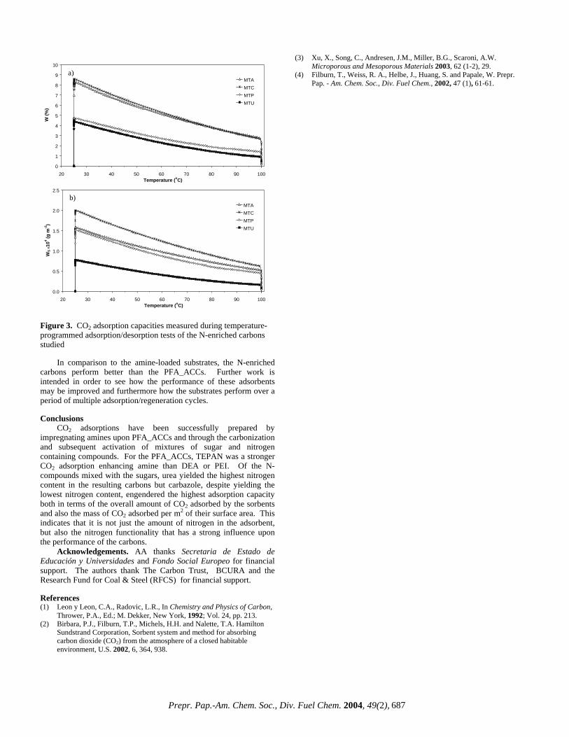
Figure 3. CO2 adsorption capacities measured during temperature-programmed adsorption/desorption tests of the N-enriched carbons studied
In comparison to the amine-loaded substrates, the N-enriched carbons perform better than the PFA_ACCs. Further work is intended in order to see how the performance of these adsorbents may be improved and furthermore how the substrates perform over a period of multiple adsorption/regeneration cycles. Conclusions
CO2 adsorptions have been successfully prepared by impregnating amines upon PFA_ACCs and through the carbonization and subsequent activation of mixtures of sugar and nitrogen containing compounds. For the PFA_ACCs, TEPAN was a stronger CO2 adsorption enhancing amine than DEA or PEI. Of the N-compounds mixed with the sugars, urea yielded the highest nitrogen content in the resulting carbons but carbazole, despite yielding the lowest nitrogen content, engendered the highest adsorption capacity both in terms of the overall amount of CO2 adsorbed by the sorbents and also the mass of CO2 adsorbed per m2 of their surface area. This indicates that it is not just the amount of nitrogen in the adsorbent, but also the nitrogen functionality that has a strong influence upon the performance of the carbons.
Acknowledgements. AA thanks Secretaria de Estado de Educación y Universidades and Fondo Social Europeo for financial support. The authors thank The Carbon Trust, BCURA and the Research Fund for Coal & Steel (RFCS) for financial support. References (1) Leon y Leon, C.A., Radovic, L.R., In Chemistry and Physics of Carbon,
Thrower, P.A., Ed.; M. Dekker, New York, 1992; Vol. 24, pp. 213. (2) Birbara, P.J., Filburn, T.P., Michels, H.H. and Nalette, T.A. Hamilton
Sundstrand Corporation, Sorbent system and method for absorbing carbon dioxide (CO2) from the atmosphere of a closed habitable environment, U.S. 2002, 6, 364, 938.
(3) Xu, X., Song, C., Andresen, J.M., Miller, B.G., Scaroni, A.W. Microporous and Mesoporous Materials 2003, 62 (1-2), 29.
0
1
2
3
4
5
6
7
8
9
10
20 30 40 50 60 70 80 90 100Temperature (oC)
W (%
)
MTAMTCMTPMTU
0.0
0.5
1.0
1.5
2.0
2.5
20 30 40 50 60 70 80 90 100Temperature (oC)
WS
x104 (g
m-2
)
MTAMTCMTPMTU
a) (4) Filburn, T., Weiss, R. A., Helbe, J., Huang, S. and Papale, W. Prepr. Pap. - Am. Chem. Soc., Div. Fuel Chem., 2002, 47 (1), 61-61.
b)
Prepr. Pap.-Am. Chem. Soc., Div. Fuel Chem. 2004, 49(2), 687
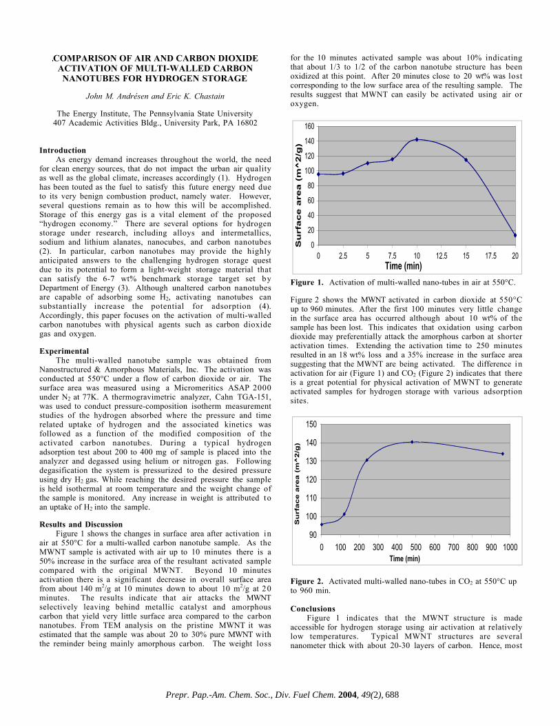
COMPARISON OF AIR AND CARBON DIOXIDEACTIVATION OF MULTI-WALLED CARBONNANOTUBES FOR HYDROGEN STORAGE
John M. Andrésen and Eric K. Chastain
The Energy Institute, The Pennsylvania State University407 Academic Activities Bldg., University Park, PA 16802
IntroductionAs energy demand increases throughout the world, the need
for clean energy sources, that do not impact the urban air qualityas well as the global climate, increases accordingly (1). Hydrogenhas been touted as the fuel to satisfy this future energy need dueto its very benign combustion product, namely water. However,several questions remain as to how this will be accomplished.Storage of this energy gas is a vital element of the proposed“hydrogen economy.” There are several options for hydrogenstorage under research, including alloys and intermetallics,sodium and lithium alanates, nanocubes, and carbon nanotubes(2). In particular, carbon nanotubes may provide the highlyanticipated answers to the challenging hydrogen storage questdue to its potential to form a light-weight storage material thatcan satisfy the 6-7 wt% benchmark storage target set byDepartment of Energy (3). Although unaltered carbon nanotubesare capable of adsorbing some H2, activating nanotubes cansubstantially increase the potential for adsorption (4).Accordingly, this paper focuses on the activation of multi-walledcarbon nanotubes with physical agents such as carbon dioxidegas and oxygen.
ExperimentalThe multi-walled nanotube sample was obtained from
Nanostructured & Amorphous Materials, Inc. The activation wasconducted at 550°C under a flow of carbon dioxide or air. Thesurface area was measured using a Micromeritics ASAP 2000under N2 at 77K. A thermogravimetric analyzer, Cahn TGA-151,was used to conduct pressure-composition isotherm measurementstudies of the hydrogen absorbed where the pressure and timerelated uptake of hydrogen and the associated kinetics wasfollowed as a function of the modified composition of theactivated carbon nanotubes. During a typical hydrogenadsorption test about 200 to 400 mg of sample is placed into theanalyzer and degassed using helium or nitrogen gas. Followingdegasification the system is pressurized to the desired pressureusing dry H2 gas. While reaching the desired pressure the sampleis held isothermal at room temperature and the weight change ofthe sample is monitored. Any increase in weight is attributed toan uptake of H2 into the sample.
Results and DiscussionFigure 1 shows the changes in surface area after activation in
air at 550°C for a multi-walled carbon nanotube sample. As theMWNT sample is activated with air up to 10 minutes there is a50% increase in the surface area of the resultant activated samplecompared with the original MWNT. Beyond 10 minutesactivation there is a significant decrease in overall surface areafrom about 140 m2/g at 10 minutes down to about 10 m2/g at 20minutes. The results indicate that air attacks the MWNTselectively leaving behind metallic catalyst and amorphouscarbon that yield very little surface area compared to the carbonnanotubes. From TEM analysis on the pristine MWNT it wasestimated that the sample was about 20 to 30% pure MWNT withthe reminder being mainly amorphous carbon. The weight loss
for the 10 minutes activated sample was about 10% indicatingthat about 1/3 to 1/2 of the carbon nanotube structure has beenoxidized at this point. After 20 minutes close to 20 wt% was lostcorresponding to the low surface area of the resulting sample. Theresults suggest that MWNT can easily be activated using air oroxygen.
0
20
40
60
80
100
120
140
160
0 2.5 5 7.5 10 12.5 15 17.5 20Time (min)
Su
rface
are
a (
m^
2/g
)
Figure 1. Activation of multi-walled nano-tubes in air at 550°C.
Figure 2 shows the MWNT activated in carbon dioxide at 550°Cup to 960 minutes. After the first 100 minutes very little changein the surface area has occurred although about 10 wt% of thesample has been lost. This indicates that oxidation using carbondioxide may preferentially attack the amorphous carbon at shorteractivation times. Extending the activation time to 250 minutesresulted in an 18 wt% loss and a 35% increase in the surface areasuggesting that the MWNT are being activated. The difference inactivation for air (Figure 1) and CO2 (Figure 2) indicates that thereis a great potential for physical activation of MWNT to generateactivated samples for hydrogen storage with various adsorptionsites.
90
100
110
120
130
140
150
0 100 200 300 400 500 600 700 800 900 1000Time (min)
Su
rfa
ce
are
a (
m^
2/g
)
Figure 2. Activated multi-walled nano-tubes in CO2 at 550°C upto 960 min.
ConclusionsFigure 1 indicates that the MWNT structure is made
accessible for hydrogen storage using air activation at relativelylow temperatures. Typical MWNT structures are severalnanometer thick with about 20-30 layers of carbon. Hence, most
Prepr. Pap.-Am. Chem. Soc., Div. Fuel Chem. 2004, 49(2), 688
of the carbon is therefore not accessible for hydrogen adsorptiondue to encapsulation by the outer layer. Further, the extremelength of the multi-walled carbon nanotubes compared to theirdiameter is limiting the storage of hydrogen within the MWNTthemselves. Hence, liberating the structure through partialoxidation as shown above can significantly introduce hydrogenadsorption sites in MWNT.
References[1] Schultz, M.G., Diehl, T., Brasseur, G.P., Zittel, W., Science, 302
(5645), 624-627, 2003[2] Dillon, A.C., Heben, M.J., Applied Physics A-Materials Science
& Processing, 72 (2), 133-142, 2001[3] Hynek, S., Fuller, W., Bentley, J., Int. J. Hydrogen Energy, 22,
601, 1997.[4] Smith, M.R., Bittner, E.W., Shi W., Johnson J.K., Bockrath B.C.,
J. Physical Chemistry B, 107 (16), 3752-3760, 2003
Prepr. Pap.-Am. Chem. Soc., Div. Fuel Chem. 2004, 49(2), 689
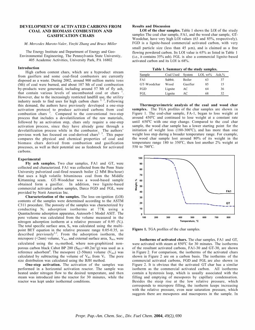
DEVELOPMENT OF ACTIVATED CARBONS FROMCOAL AND BIOMASS COMBUSTION AND
GASIFICATION CHARS
M. Mercedes Maroto-Valer, Yinzhi Zhang and Bruce Miller
The Energy Institute and Department of Energy and Geo-Environmental Engineering, The Pennsylvania State Universtiy,
405 Academic Activities, University Park, PA 16802
IntroductionHigh carbon content chars, which are a byproduct stream
from gasifiers and some coal-fired combustors are currentlydisposed as a waste. During 2002, around 900 million metric tons(Mt) of coal were burned, and about 107 Mt of coal combustionby-products were generated, including around 57 Mt of fly ash,that contain various levels of uncombusted coal or chars 1.However, due to the increasingly restricted landfill use, the utilityindustry needs to find uses for high carbon chars 2, 3. Followingthis demand, the authors have previously developed a one-stepactivation protocol to produce activated carbons from coalcombustion chars 3. Compared to the conventional two-stepprocess that includes a devolatilization of the raw materials,followed by an activation step, chars only require a one-stepactivation process, since they have already gone through adevolatilization process while in the combustor. The authors’previous work has focused on coal-derived chars2, 3. This papercompares the physical and chemical properties of coal andbiomass chars derived from combustion and gasificationprocesses, as well as their potential use as feedstock for activatedcarbons.
ExperimentalFly ash samples. Two char samples, FA1 and GT, were
collected and characterized. FA1 was collected from the Penn StateUniversity pulverized coal-fired research boiler (2 MM Btu/hour)that uses a high volatile bituminous coal from the MiddleKittanning seam. GT-Woodchar was a wood-based sampleobtained form a gasifier. In addition, two lignite-basedcommercial activated carbon samples, Darco FGD and FGL, wereprovided by Norit Americas Inc.
Characterization of the samples. The loss–on-ignition (LOI)contents of the samples were determined according to the ASTMC311 procedure. The porosity of the samples was characterized byconducting N2 adsorption isotherms at 77K using aQuantachrome adsorption apparatus, Autosorb-1 Model ASIT. Thepore volume was calculated from the volume measured in thenitrogen adsorption isotherm at a relative pressure of 0.95 (Vt).The total specific surface area, St, was calculated using the multi-point BET equation in the relative pressure range 0.05-0.35, asdescribed previously2,3. From the adsorption isotherm, themicropore (<2nm) volume, Vmi, and external surface area, Smi, werecalculated using the αS-method, where non-graphitized non-porous carbon black Cabot BP 280 (SBET=40.2m2/g) was used as areference adsorbent4. The mesopore (2-50nm) volume (Vme) wascalculated by subtracting the volume of Vmi from Vt. The poresize distribution was calculated using the BJH method.
One-step activation. The activation of the samples wasperformed in a horizontal activation reactor. The sample washeated under nitrogen flow to the desired temperature, and thensteam was introduced into the reactor for 30 minutes, while thereactor was kept under isothermal conditions.
Results and DiscussionLOI of the char samples. Table 1 shows the LOI of the study
samples The coal char sample, FA1, and the wood char sample, GT-Woodchar, have very high LOI values (63 and 85%, respectively). FGD is a lignite-based commercial activated carbon, with verysmall particle size (less than 45 µm), and is claimed as a freeflowing powdered carbon. Its LOI value is 65% as listed in Table 1(i.e., it contains 35% ash). FGL is also a commercial lignite-basedactivated carbon and its LOI is 68%.
Table 1. Summary of the study samples.
Sample Coal Used System LOI, wt% Ash,%
FA1 Subbit. Boiler 63 37GT-Woodchar Wood Gasifier 85 15FGD Lignite AC 64 36FGL Lignite AC 68 32
Thermogravimetric analysis of the coal and wood charsamples. The TGA profiles of the char samples are shown inFigure 1. The coal-char sample, FA-1, began to loss weight ataround 450oC and continued to lose weight at a constant rateuntil 650oC with one step change. Compared to the coal charsample, the wood char sample has a lower starting point for theinitiation of weight loss (180-300oC), and has more than oneweight loss step during a broader temperature range. For example,the wood char sample lost around 80% of its weight in thetemperature range 180 to 350oC, then lost another 2% weight at550 to 700oC.
0
10
20
30
40
50
60
70
80
90
100
100 200 300 400 500 600 700 800
Temperature, °C
Wei
gh
t, %
FA1
GT
Figure 1. TGA profiles of the char samples.
Isotherms of activated chars. The char samples, FA1 and GT,were activated with steam at 850oC for 30 minutes. The isothermsof the resultant activated carbons, FA1-30 and GT-30, are shownin Figure 2. For comparison, the isotherms of the activated charsshown in Figure 2 are on a carbon basis. The isotherms of thecommercial activated carbons, FGD and FGL are also shown inFigure 2. It is obvious that the activated GT char has a similarisotherm as the commercial activated carbon. All isothermscontain a hysteresis loop, which is usually associated with thefilling and emptying of mesopores by capillary condensation.Besides the steep rise at the low relative pressure, whichcorresponds to micropore filling, the isotherm keeps increasingwith the relative pressure, even near saturation pressure, whichsuggests there are mesopores and macropores in the sample. In
Prepr. Pap.-Am. Chem. Soc., Div. Fuel Chem. 2004, 49(2), 690

contrast, activated coal-based char, FA1-30, has a near type 1isotherm, which features a steep increase at low relative pressureand levels off at higher relative pressure. However, compared tothe raw char, both activated char samples (FA1-30 and GT-30)have much more developed porosity after the 30 minutes one-stepactivation process.
0
50
100
150
200
250
300
350
400
0.0 0.2 0.4 0.6 0.8 1.0
Relative Pressure, P/Po
Vo
lum
e A
dso
rbed
, m
l/g
C,
STP FA1-30 GT-30
FGD FGL
Figure 2. Isotherms of activated chars (FA1-30 and GT-30) andcommercial activated carbons (FGD and FGL)
Pore surface area and volume distribution of activatedchars. The surface area and pore volume distribution of thesamples were calculated from the isotherms presented in Figure 2using the alpha-s method and the results are presented in Figures3 and 4.
0
100
200
300
400
500
600
Su
rface A
rea,
m2/
g
GTI-30 FA1-30 FGD FGL
Mesopore area
Micropore area
Figure 3. The surface area distribution of the activated chars (GT-30 and FA-30) and commercial activated carbons (FGD and FGL)
The activated GT sample has the greatest surface area(564m2/g) on a carbon basis, of which 317m2/g is contributedfrom mesopores, which account for ≈56% of the total. Thecommercial activated carbon FGD has a surface area of 526m2/g,and ≈53% (275m2/g) is from mesopores. Corresponding to itsdifferent isotherm shape, activated FA1 has only 13% surface areathat is contributed from mesopores (54 vs. 409m2/g).
FGD has a total pore volume of 0.473 ml/g and 77% of thepore volume is from mesopores. GT-30 has a similar pore volumedistribution, with a total pore volume of 0.447ml/g of which≈73% is from mesopores. Activated FA1 has more micropores anda larger mesopore volume, but the mesopores only account for25% of the total pore volume.
0
0.05
0.1
0.15
0.2
0.25
0.3
0.35
0.4
0.45
0.5
Po
re V
olu
me,
ml/
g
GTI-30 FA130 FGD FGL
Micropore Volume Mesopore Volume
Figure 4. The pore volume distribution of the activated chars (GT-30 and FA-30) and commercial activated carbons (FGD and FGL)
ConclusionsOf the samples collected, the wood-based sample has higher
LOI than the coal-based samples. The lignite-based commercialactivated carbon, Darco FGD, contains 35% ash. The wood-basedsample has a lower starting point for weight loss (180-300oC vs.200-400oC) than the coal based char, and its thermal reaction i smore complex. Compared to the raw char (FA1 and GT), bothactivated char samples (FA1-30 and GTI-30) have much moredeveloped porosity after the 30 minutes one-step activationprocess. The activated GT sample has surface area as high as564m2/g on a carbon basis, which is comparable to thecommercial activated carbon FGD of 526m2/g. The mesoporosityof activated GT char is 56% on a surface basis or 73% on a volumebasis. This is comparable to the commercial activated carbonFGD, which is 53% is on a surface basis or 77% on a volume basis.Both samples have a porous structure containing a large amountof mesopores, suggesting that they will have good mass transferproperties.
Acknowledgements. The authors would like to acknowledgethe Consortium for Premium Carbon Products from Coal (DOEAward number: DE-FC26-98FT40350; Internal AgreementNumber: 2482-TPSU-DOE-0350) for financial support.
References(1) Kalyoncu RS. Coal Combustion Products, U.S. Geological
Survey Minerals Yearbook, 2000(2) Maroto-Valer MM, Schobert HH. Carbonaceous combustion
waste as precursor for activated carbons, 24th Biennial Conf.on Carbon, 1999, Charleston, 1, 588-589
(3) Zhang YZ, Lu Z, Maroto-Valer MM, Andresen JM, SchobertHH. Comparison of High-Unburned-Carbon Fly Ashes fromDifferent Combustor Types and Their Steam ActivatedProducts, Energy & Fuels, 2003:17, 369-377
(4) Kruk, M.; Jaroniec, M.; Gadkaree, K.P., J. Colloid InterfaceSci., 1997, 192, 250
Prepr. Pap.-Am. Chem. Soc., Div. Fuel Chem. 2004, 49(2), 691
EFFECT OF γ-IRRADIATION OF ACTIVATED CARBONS ON THE GENERATION OF NEW FREE
RADICALS AND POROSITY
Demet Erçin1, Mahmut Eken1, Zeki Aktas2, Sevil Çetinkaya3, Billur Sakintuna4 and Yuda Yürüm4
1Materials Research Department, Ankara Nuclear Research and
Training Center, Besevler, 06100 Ankara, Turkey 2Department of Chemical Engineering, Ankara University,
Besevler, 06100 Ankara, Turkey 3Department of Chemistry, Hacettepe University, Beytepe,
06532 Ankara, Turkey 4Faculty of Engineering and Natural Sciences, Sabanci
University, Tuzla, 34956 Istanbul, Turkey Introduction Ion beam irradiation is one approach that has been utilized to modify macromolecular materials primarily by alteration of the macromolecular structure or chemical composition of the carbon materials1. The erosion of polymer surfaces by high energy ions or particles is of interest for polymers used in space vehicles2,3. It is reported that little is known about the radiolysis of condensed organic materials with heavy ions4. The radiolysis of active carbons with γ-rays is not an extensively studied topic. Products of such an interaction should be a complex mixture of ions, free radicals and simple molecules and a solid restructured carbonaceous material. Originally present and/or newly created organic free radicals in carbonaceous solids have been shown to interact with paramagnetic gases such as oxygen5. The interactions between a paramagnetic gas and organic free radicals occur over short distances, typically on the order of a few nanometers and often result in measurable broadening of ESR spectral lines6. Because of this short interaction distance, free radicals accessible to oxygen are expected to be located on or just beneath the external and internal surfaces of carbonaceous solids. Such interactions thus are expected to form new structures on the surface of carbon materials In this paper the results of the surface treatment of activated carbons prepared from Turkish Elbistan lignite with γ-irradiation from a 60Co source are presented and associated modification of the structure of the activated carbon is discussed in terms of changes in surface area and free radical concentration. Experimental
Materials. Elbistan lignite was used in the study. Analysis of the Elbistan lignite is presented in Table 1. The lignite sample was ground under a nitrogen atmosphere to 100 µm size and stored under nitrogen.
Table 1. Proximate and Elemental Analysis of Elbistan
Lignite
Pyrolysis experiments. Coal samples were dried at 100°C
an inert atmosphere. 8.00 g sample was placed into a porcelain
crucible and then placed into a furnace purged with ultra high-purity nitrogen. Coal samples were heated to four different temperatures 500, 700, 800, 900 and 1000°C with a heating rate of 10°C/min, under a nitrogen flow of 100 ml/min for 120 minutes. After the pyrolysis experiments, chars were cooled to room temperature under the nitrogen flow.
Activation experiments. Chars were activated under a carbon dioxide flow of 100 ml/min at the final pyrolysis temperature for an additional two hours. System was cooled to room temperature under the nitrogen flow.
Irradiation experiments. A PX-γ-30 60Co gamma cell having a dose rate of 1.85 kGyh-1 at room temperature was used for γ-radiolysis. The dose rate profile of the gamma source was determined by Fricke dosimetry.
Surface analysis. Surface areas of activated carbons were measured by ASAP2000 Accelerated Surface Area and Porosimetry system manufactured by Micromeritics Co., USA. Surface area of the samples was determined by using BET equation in the relative pressure range of between 0.05 to 0.25, over five adsorption points.
FTIR spectrometry. FT-IR spectra of activated carbon samples were measured with a Bruker EQUINOX 55 FT-IR spectrometer. Activated carbon samples were dried under a nitrogen atmosphere at 110oC for 24 hours. KBr pellets were prepared by grinding 2.5 mg of dry sample with 200 mg of dried KBr. Spectra were obtained with 200 scans at a resolution 2 cm-1.
ESR spectroscopy. ESR spectra of the activated carbon samples, 20 mg, transferred into tubes of 4 mm i.d. were recorded using a Bruker EMX ESR spectrometer operating at 9.6 GHz, with a single cavity resonator, 3300 field set, 100 kHz field modulation, 0.50 G peak to peak modulation amplitude and 0.6 mW microwave power to determine the radical concentrations, signal intensities, linewidths and g values. All spin concentration measurements were performed using a standard DPPH sample in the cavity of the resonator. The intensity of the ESR signal is proportional to the number of free radicals in the sample and is, therefore, an indication of the spin density. Relative spin density Ns-rel is calculated from the ratio of the relative intensities of the samples to that of the raw lignite7.
Results and Discussion
BET areas of irradiated samples are measured to be greater than those of non-irradiated samples, shown in Figure 1. This might be considered as an indication to surface erosion by high energy ions and particles as it was observed by Young and Slemp2, on polymer surfaces. BET areas of both irradiated and non-irradiated samples of activated carbons increased up to 800oC. The BET areas of the samples produced at 900oC and 1000oC decreased to lower values than those of measured for samples obtained at 800oC. The reason for the decrease of BET areas in samples obtained at temperatures higher than 800oC might be the melting of the minerals originally present in the raw lignite samples and clogging of the porosity in the carbons by the glassy structures formed at these temperatures during pyrolysis and activation experiments.
Proximate Analysis %, dry Volatiles 44.8 Fixed Carbon 20.9 Ash 34.3 Elemental Analysis %, dmmf C 53.0 H 5.8 N 1.8 S 3.6 O (by difference) 35.8
Percent increase in BET areas of the irradiated samples relative to non-irradiated samples is presented in Figure 2. Surface erosion by high energy ions and particles seemed to increase as the temperature of activation was increased. A steady increase in the BET areas was observed in samples obtained in the range of 500-900oC. The effect was amplified in the irradiated sample obtained at 1000oC. While the percent difference was in the range of 5-22 for the samples obtained between 500oC and 900oC, the percent difference sharply increased to 372 between the non-irradiated and irradiated samples obtained at 1000oC.
ESR peak widths, (∆Hpp), g values and relative intensities of activated carbons were given in Table 2 and 3. ESR peak intensities increased between 700°C and 900°C.
Prepr. Pap.-Am. Chem. Soc., Div. Fuel Chem. 2004, 49(2), 692

Figure 1. Change of BET area with temperature of activation for non-irradiated and irradiated samples. Figure 2 een non-
Table 2. ESR Peak Width and G Values Before and After
Activation
ir n
wi values g
values
. Change of percent BET area increase betwirradiated and irradiated samples with activation temperature.
Irradiation of the Activated Carbons.
Peak Peak g Temp., oC width
before radiatio(∆Hpp), Gauss
dth afterirradiation
(∆Hpp), Gauss
before irradiation
after irradiation
Raw lignite 5.4 2.0041 2.0030 6.3 500 6.5 6.9 2.0035 2.0018 700 78.2 78.2 1.9869 2.1080 800 850.4 855.3 2.0481 2.0455 900 830.9 821.1 2.0560 2.0590 1000 909.1 1026.4 2.1330 2.1804
Table 3. ESR Relative Intensity Before and After Irradiation
Activation Temp.,
of the Activated Carbons.
Relative intensity Relative intensity oC before irradiation after irradiation
Raw lignite 1 1 500 5 5 700 27 19 800 39055 38403 900 47870 45903 1000 35943 44764
Radi l concentration was decreased in the temperatures high
13C NMR spectra of raw Elbistan lignite and irradiated activated carbons at different temperatures were shown in Figure 3 and Figure 4 respectively. According to Figure 4, peak intensities of C-H bonds in the NMR spectra, decreased with increasing temperature. sp, sp2 and sp3 hybridized carbons were observed in these spectra .
Figure 3. 13C NMR of Non-Irradiated, Original Elbistan Lignite Figure 4. A. 13C NMR of irradiated activated carbon at 500°C, B. at 700°C, C. at 800°C, D. at 900°C.
Figure 5. FTIR spectra of Raw Elbistan Lignite. FTIR spectra of raw Elbistan Lignite was shown in Figure 5. Both in irradiated and non-irradiated activated carbons, functional groups were increased with increasing temperature. With irradiation, peak intensities in FTIR spectrums were also increased. Porous carbon material have characteristic bands near 3500 cm-1, 1600 cm-1 and 1430 cm-1 are due to OH stretching, aromatic C-H absorption due to the aromatic structure of resultant carbon and C-O, C-C groups. References 1. M.Celina; H. Kudoh; T.J. Renk; K.T. Gillen; R.L. Clough
Radiat.Phys.Chem. 1998, 51, 191. 2. Young P.R.; Slemp W.S. Polymer Preparation 1990, 31, 353. 3. Young P.R.; Siochi E.J.; Slemp W.S. Polymer Preparation
1994, 35, 916. 4. LaVerne; J.A. Chang Z.; Araos M.S. Radiat.Phys.Chem. 2001,
60, 253. 5. Van Krevelen D.W.; Elsevier: Amsterdam, 1993. 6. Subczynski W.K.; Hyde J.S. Biophys. J. 1984, 45, 743. 7. Erçin D.; Tanyolaç A.; Korkmaz M.; Yurum, Y. Fuel
Processing Technology 2001, 69, 95-106. 8. Pilawa B.; Wieckkowski A.B.; Lewandowski M.; Reson M.
Chem. 1999, 37, 871-877..
0
50
100
150
200
250
0 200 400 600 800 1000 1200
Activation Temperature, oC
BE
T A
rea,
m2 /g
non-irradiatedirradiated
050
100150200250300350400
200 400 600 800 1000 1200Activation Temperature, oC
Incr
ease
in B
ET
Are
a, %
A
B
C
D
caer than 600oC. The g value of activated carbons was
increased at 600°C, similar to recombination reactions. Decreasing peak intensity and increasing g value at 1000°C was due to disappearing radical concentration. ESR peak widths were increased with increasing temperature. It is known that paramagnetic groups is increasing up to 550°C8. At high temperatures peak widths were increased. g values were increased with increasing temperature. ESR peak width (∆Hpp) and peak intensities of original Elbistan Lignite and activated carbons did not change after irradiated.
Prepr. Pap.-Am. Chem. Soc., Div. Fuel Chem. 2004, 49(2), 693

Investigation of The Structural Changes in Freeze-dried Low-rank Turkish Coals and in
Their Supercritical Extracts
Serkan Bas, Billur Sakintuna, Burak Birkan, Yusuf Menceloglu, Alpay Taralp, and Yuda Yürüm
Faculty of Engineering and Natural Sciences,
Sabanci University, Tuzla, Istanbul 34956, Turkey
Introduction Coal structure consists of asset of clusters attached by
groups containing bonds potentially capable of undergoing free rotation1. The clusters contain aromatic and hydroaromatic systems. Most of the clusters are divalent, that is covalently bonded to only two other clusters. Some portion of the clusters are tri- or higher valent so that tridimensional macromolecules exist in the coal structures. Their presence in the coal causes the whole system to be linked into one large molecule, one in which a chain of covalent bonds attaches any atom to all other atoms. In addition to the covalent branch points, many branch points exist because of hydrogen bonding. Strongly basic solvents can break coal-coal hydrogen bonds. The results of solvent swelling in strongly basic solvents would be quite different from those obtained with the solvents which do not break hydrogen bonds. Swelling experiments are useful in terms of investigation and modification of the coal structure1,2.
Lyophilizing is used to eliminate solvents in the interest of solute without destroying the structure reached after freezing. It is based on sublimation of freezed solvent under vacuum.
Turkish Beypazari and Elbistan lignite samples were swolen in ethylene diamine and dimethyl sulfoxide, in the present work. The change of surface area and morphology of the coal particles after swelling and lyophilization experiments were compared with those of untreated samples. Experimental
Beypazari and Elbistan lignite samples were used in the present work. Elemental analyses3 of these are given in the Table 1.
Table 1. Elemental Analysis of the Lignites Used, dmmf
Elements Beypazari Elbistan C 65.2 62.7 H 5.4 4.7 N 2.1 0.8 S (total) 5.4 4.0 O (by diff.) 21.9 27.8 The lignite samples were ground to –100 mesh size before
using. The swelling behavior of the lignite samples was studied by Liotta’s method4. Approximately 100 mg of a sample was placed in a 6 mm o.d. tube and centrifuged for 10 minutes at 5000 rev/min. The height of the sample was measured as h1. Excess ethylenediamine or dimethylsulfoxide (∼1 ml) was added into the tube and the contents of the tube were mixed and the tube was centrifuged after 24 hours and the height of the sample in the tube (h2) was measured. Swelling kinetics of dried coals were determined until equilibrium.
The swollen Elbistan and Beypazari lignite samples were frozen in two different ways before lyophilization. The first method was to freeze samples directly in liquid N2 . In the other method pre-cooled samples at -20oC were then frozen in liquid N2 as it was in the first method. The samples were lyophilized at room temperature and a pressure of 0.120 mbar by using a Christ
ALPHA 1-2 LD lyophilizer. The lyophilized and raw samples were examined with a Gemini scanning electron microscope. All samples were coated with gold before taking any image because of insufficient conducting of the lignite samples. The change in the structure after lyophilization was compared with those of the raw samples.
Lyophilized samples were treated with supercritical carbon dioxide in a Thermo Haake C35P supercritical system at 50 bar and 80oC. Raw samples and supercritically treated samples were extracted in tetrahydrofuran digestively, for 24h at 20oC and in 130 rpm. Extracts obtained were analyzed using a Shimadzu GC-17A GC-MS system. The surface area of the raw and treated samples were measured using an ASAP 2000 Accelerated Surface Area and Porosimetry system manufactured by Micromeritics Co., USA.
Results and Discussion
Swelling ratios of Beypazari and Elbistan lignites in dimethylsulfoxide and ethylenediamine were measured until equilibrium values were attained. The swelling ratio of Beypazari lignite sample in dimethylsulfoxide and of Elbistan lignite sample in ethylenediamine were measured as 1.42 and 1.46, respectively.
Figure 1. Micrograph of raw Elbistan lignite sample.
Figure 2. Micrograph of pre-cooled to –20oC and then cooled in liquid nitrogen and lyophilized Elbistan lignite sample.
Micrographs of raw and treated lignite samples (Figures 1-
6) indicated the presence of disintegrated particles in the solvent swollen and lyophilized samples. Particles seemed to develop new porosity on the surface. Surface areas of the treated samples increased compared to those of the raw samples. GC-MS analyses revealed differences in the composition of THF extracts obtained after supercritical carbon dioxide treated lyophilized lignite samples. The components present in the total ion chromatograms (TIC) of the raw lignite (Figure 7) seemed to contain fewer number of peaks compared to those of TIC’s of the extracts of treated lignite samples (Figure 8 and 9). Mass spectra of the components identified in the TIC’s indicated the presence of complex structures in the extracts.
Prepr. Pap.-Am. Chem. Soc., Div. Fuel Chem. 2004, 49(2), 694
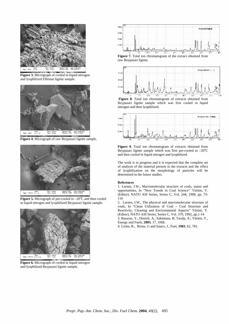
Figure 3. Micrograph of cooled in liquid nitrogen and lyophilized Elbistan lignite sample.
Figure 4. Micrograph of raw Beypazari lignite sample.
Figure 5. Micrograph of pre-cooled to –20oC and then cooled in liquid nitrogen and lyophilized Beypazari lignite sample.
Figure 6. Micrograph of cooled in liquid nitrogen and lyophilized Beypazari lignite sample.
Figure 7. Total ion chromatogram of the extract obtained from raw Beypazari lignite.
Figure 8. Total ion chromatogram of extracts obtained from Beypazari lignite sample which was first cooled in liquid nitrogen and then lyophilized.
Figure 9. Total ion chromatogram of extracts obtained from Beypazari lignite sample which was first pre-cooled to –20oC and then cooled in liquid nitrogen and lyophilized. The work is in progress and it is expected that the complete set of analysis of the material present in the extracts and the effect of lyophilization on the morphology of particles will be determined in the future studies. References 1. Larsen, J.W., Macromolecular structure of coals, status and opportunities, In “New Trends in Coal Science” Yürüm, Y. (Editor), NATO ASI Series, Series C, Vol. 244, 1988, pp. 73-116 2. Larsen, J.W., The physical and macromolecular structure of coals, In “Clean Utilization of Coal – Coal Structure and Reactivity, Cleaning and Environmental Aspects” Yürüm, Y. (Editor), NATO ASI Series, Series C, Vol. 370, 1992, pp.1-14 3. Basaran, Y.; Denizli, A.; Sakintuna, B; Taralp, A.; Yürüm, Y., Energy and Fuels, 2003, 17, 1068.4. Liotta, R., Brons, G and Isaacs, J., Fuel, 1983, 62, 781.
Prepr. Pap.-Am. Chem. Soc., Div. Fuel Chem. 2004, 49(2), 695
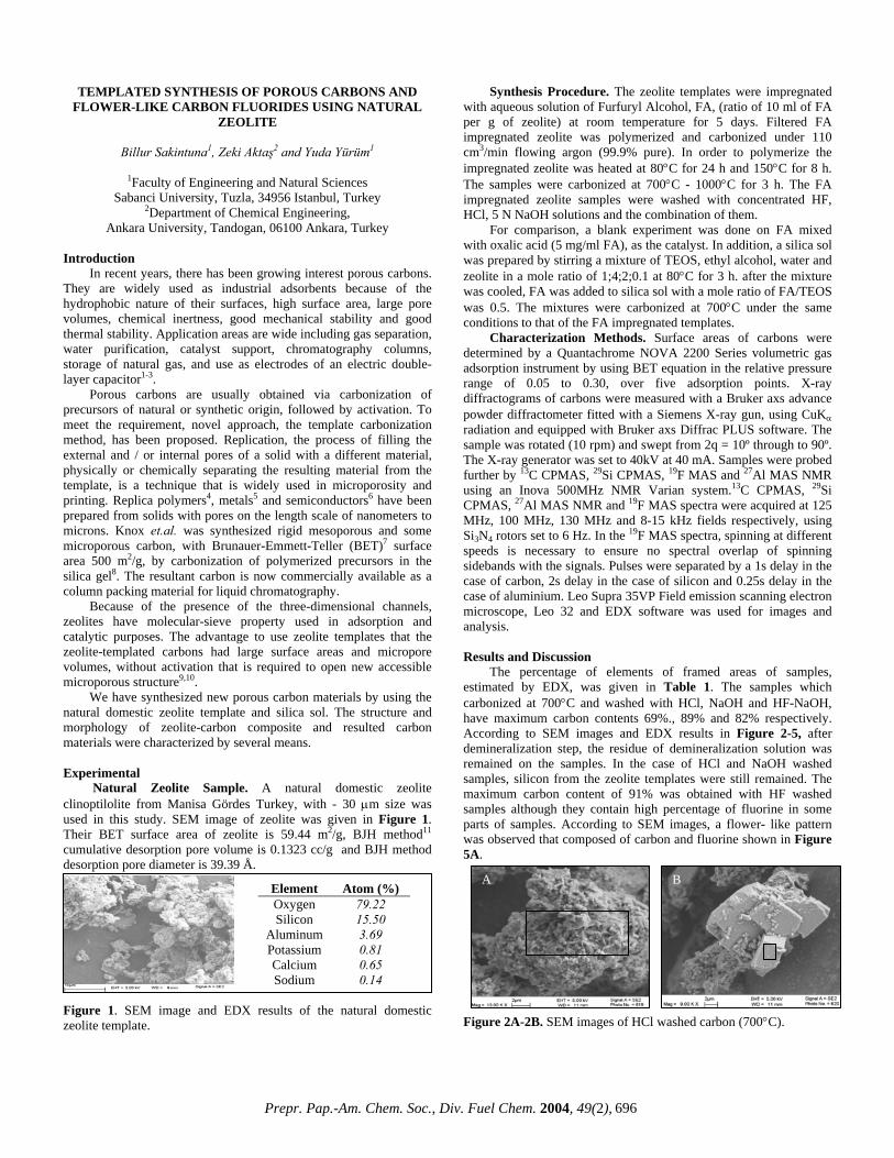
TEMPLATED SYNTHESIS OF POROUS CARBONS AND FLOWER-LIKE CARBON FLUORIDES USING NATURAL
ZEOLITE
Billur Sakintuna1, Zeki Aktaş2 and Yuda Yürüm1
1Faculty of Engineering and Natural Sciences
Sabanci University, Tuzla, 34956 Istanbul, Turkey 2Department of Chemical Engineering,
Ankara University, Tandogan, 06100 Ankara, Turkey Introduction
In recent years, there has been growing interest porous carbons. They are widely used as industrial adsorbents because of the hydrophobic nature of their surfaces, high surface area, large pore volumes, chemical inertness, good mechanical stability and good thermal stability. Application areas are wide including gas separation, water purification, catalyst support, chromatography columns, storage of natural gas, and use as electrodes of an electric double-layer capacitor1-3.
Porous carbons are usually obtained via carbonization of precursors of natural or synthetic origin, followed by activation. To meet the requirement, novel approach, the template carbonization method, has been proposed. Replication, the process of filling the external and / or internal pores of a solid with a different material, physically or chemically separating the resulting material from the template, is a technique that is widely used in microporosity and printing. Replica polymers4, metals5 and semiconductors6 have been prepared from solids with pores on the length scale of nanometers to microns. Knox et.al. was synthesized rigid mesoporous and some microporous carbon, with Brunauer-Emmett-Teller (BET)7 surface area 500 m2/g, by carbonization of polymerized precursors in the silica gel8. The resultant carbon is now commercially available as a column packing material for liquid chromatography.
Because of the presence of the three-dimensional channels, zeolites have molecular-sieve property used in adsorption and catalytic purposes. The advantage to use zeolite templates that the zeolite-templated carbons had large surface areas and micropore volumes, without activation that is required to open new accessible microporous structure9,10.
We have synthesized new porous carbon materials by using the natural domestic zeolite template and silica sol. The structure and morphology of zeolite-carbon composite and resulted carbon materials were characterized by several means. Experimental
Natural Zeolite Sample. A natural domestic zeolite clinoptilolite from Manisa Gördes Turkey, with - 30 µm size was used in this study. SEM image of zeolite was given in Figure 1. Their BET surface area of zeolite is 59.44 m2/g, BJH method11 cumulative desorption pore volume is 0.1323 cc/g and BJH method desorption pore diameter is 39.39 Å.
Figure 1. SEM image and EDX results of the natural domestic zeolite template.
Synthesis Procedure. The zeolite templates were impregnated with aqueous solution of Furfuryl Alcohol, FA, (ratio of 10 ml of FA per g of zeolite) at room temperature for 5 days. Filtered FA impregnated zeolite was polymerized and carbonized under 110 cm3/min flowing argon (99.9% pure). In order to polymerize the impregnated zeolite was heated at 80°C for 24 h and 150°C for 8 h. The samples were carbonized at 700°C - 1000°C for 3 h. The FA impregnated zeolite samples were washed with concentrated HF, HCl, 5 N NaOH solutions and the combination of them.
For comparison, a blank experiment was done on FA mixed with oxalic acid (5 mg/ml FA), as the catalyst. In addition, a silica sol was prepared by stirring a mixture of TEOS, ethyl alcohol, water and zeolite in a mole ratio of 1;4;2;0.1 at 80°C for 3 h. after the mixture was cooled, FA was added to silica sol with a mole ratio of FA/TEOS was 0.5. The mixtures were carbonized at 700°C under the same conditions to that of the FA impregnated templates.
Characterization Methods. Surface areas of carbons were determined by a Quantachrome NOVA 2200 Series volumetric gas adsorption instrument by using BET equation in the relative pressure range of 0.05 to 0.30, over five adsorption points. X-ray diffractograms of carbons were measured with a Bruker axs advance powder diffractometer fitted with a Siemens X-ray gun, using CuKα radiation and equipped with Bruker axs Diffrac PLUS software. The sample was rotated (10 rpm) and swept from 2q = 10º through to 90º. The X-ray generator was set to 40kV at 40 mA. Samples were probed further by 13C CPMAS, 29Si CPMAS, 19F MAS and 27Al MAS NMR using an Inova 500MHz NMR Varian system.13C CPMAS, 29Si CPMAS, 27Al MAS NMR and 19F MAS spectra were acquired at 125 MHz, 100 MHz, 130 MHz and 8-15 kHz fields respectively, using Si3N4 rotors set to 6 Hz. In the 19F MAS spectra, spinning at different speeds is necessary to ensure no spectral overlap of spinning sidebands with the signals. Pulses were separated by a 1s delay in the case of carbon, 2s delay in the case of silicon and 0.25s delay in the case of aluminium. Leo Supra 35VP Field emission scanning electron microscope, Leo 32 and EDX software was used for images and analysis. Results and Discussion
The percentage of elements of framed areas of samples, estimated by EDX, was given in Table 1. The samples which carbonized at 700°C and washed with HCl, NaOH and HF-NaOH, have maximum carbon contents 69%., 89% and 82% respectively. According to SEM images and EDX results in Figure 2-5, after demineralization step, the residue of demineralization solution was remained on the samples. In the case of HCl and NaOH washed samples, silicon from the zeolite templates were still remained. The maximum carbon content of 91% was obtained with HF washed samples although they contain high percentage of fluorine in some parts of samples. According to SEM images, a flower- like pattern was observed that composed of carbon and fluorine shown in Figure 5A. Figure 2A-2B. SEM images of HCl washed carbon (700°C).
Element Atom (%) Oxygen 79.22 Silicon 15.50
Aluminum 3.69 Potassium 0.81 Calcium 0.65 Sodium 0.14
A B
A B
Prepr. Pap.-Am. Chem. Soc., Div. Fuel Chem. 2004, 49(2), 696
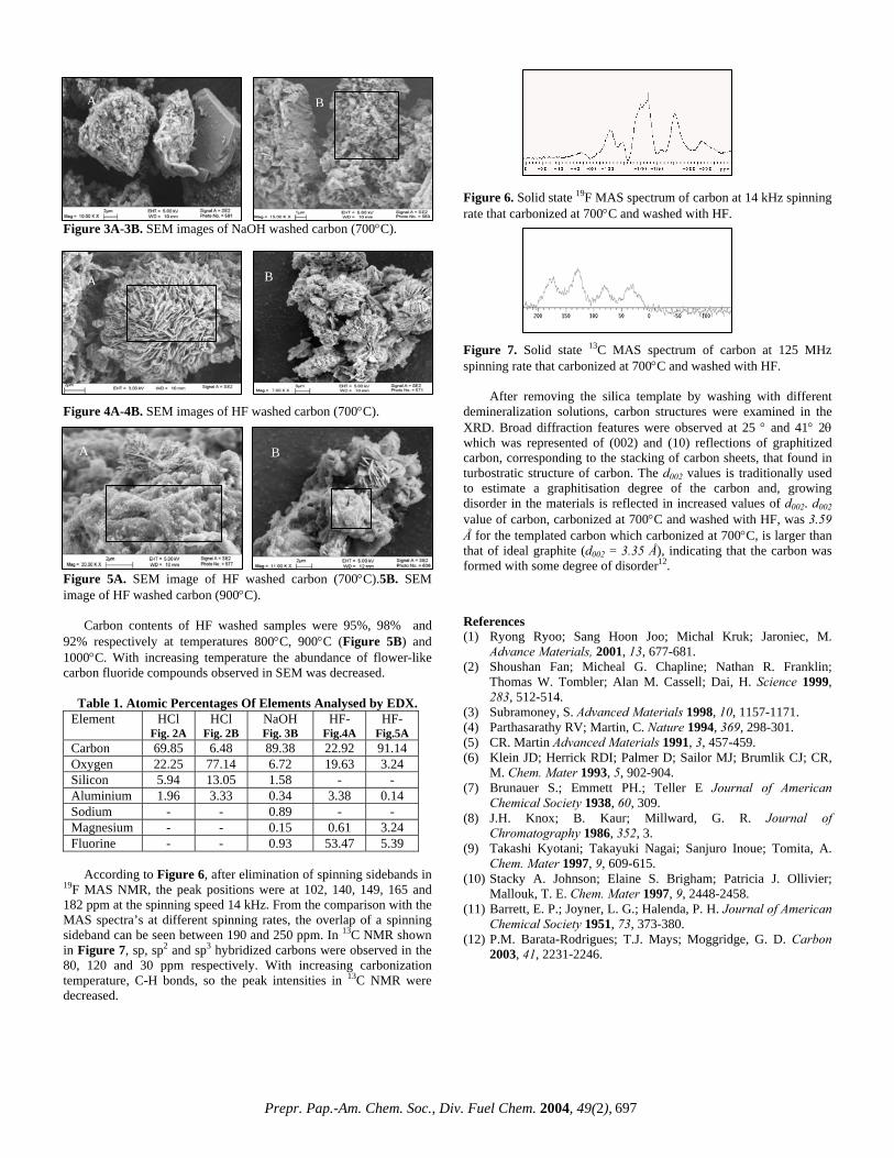
Figure 3A-3B. SEM images of NaOH washed carbon (700°C). Figure 4A-4B. SEM images of HF washed carbon (700°C). Figure 5A. SEM image of HF washed carbon (700°C).5B. SEM image of HF washed carbon (900°C). Carbon contents of HF washed samples were 95%, 98% and 92% respectively at temperatures 800°C, 900°C (Figure 5B) and 1000°C. With increasing temperature the abundance of flower-like carbon fluoride compounds observed in SEM was decreased.
Table 1. Atomic Percentages Of Elements Analysed by EDX. Element HCl
Fig. 2A HCl
Fig. 2B NaOH Fig. 3B
HF-Fig.4A
HF-Fig.5A
Carbon 69.85 6.48 89.38 22.92 91.14 Oxygen 22.25 77.14 6.72 19.63 3.24 Silicon 5.94 13.05 1.58 - - Aluminium 1.96 3.33 0.34 3.38 0.14 Sodium - - 0.89 - - Magnesium - - 0.15 0.61 3.24 Fluorine - - 0.93 53.47 5.39
According to Figure 6, after elimination of spinning sidebands in 19F MAS NMR, the peak positions were at 102, 140, 149, 165 and 182 ppm at the spinning speed 14 kHz. From the comparison with the MAS spectra’s at different spinning rates, the overlap of a spinning sideband can be seen between 190 and 250 ppm. In 13C NMR shown in Figure 7, sp, sp2 and sp3 hybridized carbons were observed in the 80, 120 and 30 ppm respectively. With increasing carbonization temperature, C-H bonds, so the peak intensities in 13C NMR were decreased.
AA B
Figure 6. Solid state 19F MAS spectrum of carbon at 14 kHz spinning rate that carbonized at 700°C and washed with HF. A B A Figure 7. Solid state 13C MAS spectrum of carbon at 125 MHz spinning rate that carbonized at 700°C and washed with HF.
After removing the silica template by washing with different demineralization solutions, carbon structures were examined in the XRD. Broad diffraction features were observed at 25 ° and 41° 2θ which was represented of (002) and (10) reflections of graphitized carbon, corresponding to the stacking of carbon sheets, that found in turbostratic structure of carbon. The d002 values is traditionally used to estimate a graphitisation degree of the carbon and, growing disorder in the materials is reflected in increased values of d002. d002 value of carbon, carbonized at 700°C and washed with HF, was 3.59 Å for the templated carbon which carbonized at 700°C, is larger than that of ideal graphite (d002 = 3.35 Å), indicating that the carbon was formed with some degree of disorder12.
A B
References (1) Ryong Ryoo; Sang Hoon Joo; Michal Kruk; Jaroniec, M.
Advance Materials, 2001, 13, 677-681. (2) Shoushan Fan; Micheal G. Chapline; Nathan R. Franklin;
Thomas W. Tombler; Alan M. Cassell; Dai, H. Science 1999, 283, 512-514.
(3) Subramoney, S. Advanced Materials 1998, 10, 1157-1171. (4) Parthasarathy RV; Martin, C. Nature 1994, 369, 298-301. (5) CR. Martin Advanced Materials 1991, 3, 457-459. (6) Klein JD; Herrick RDI; Palmer D; Sailor MJ; Brumlik CJ; CR,
M. Chem. Mater 1993, 5, 902-904. (7) Brunauer S.; Emmett PH.; Teller E Journal of American
Chemical Society 1938, 60, 309. (8) J.H. Knox; B. Kaur; Millward, G. R. Journal of
Chromatography 1986, 352, 3. (9) Takashi Kyotani; Takayuki Nagai; Sanjuro Inoue; Tomita, A.
Chem. Mater 1997, 9, 609-615. (10) Stacky A. Johnson; Elaine S. Brigham; Patricia J. Ollivier;
Mallouk, T. E. Chem. Mater 1997, 9, 2448-2458. (11) Barrett, E. P.; Joyner, L. G.; Halenda, P. H. Journal of American
Chemical Society 1951, 73, 373-380. (12) P.M. Barata-Rodrigues; T.J. Mays; Moggridge, G. D. Carbon
2003, 41, 2231-2246.
Prepr. Pap.-Am. Chem. Soc., Div. Fuel Chem. 2004, 49(2), 697
Plane of Zero Concentration in a Catalyst Slab with a Reacting Interface
Dr. Kal Renganathan Sharma PE
Formerly Principal, Sakthi Engineering College
Anna University Affilaited, (opp. MGR Gardens), Rampuram Chennai Tamil Nadu, India
Email: [email protected] Abstract The Cattaneo-Vernotte non-Fick diffusion and relaxation hyperbolic damped wave equation was solved for by transformation to the wave coordinates. The resulting equation was transformed using Laplace transform and the solution of composite Bessel function of the fist kind and zeroth order was found. An exponential decay in time for the concentration at the boundary of a semi-infinite medium was considered. The solution is damped oscillatory; u = exp(-τ/2) J0 (½ sqrt(Xτ - X2)) The plane of zero concentration occurs when 2.49 = Xτ - X2. This is much before the wave front. Introduction Morse & Feshbach (1) hypothesized and Cattaneo (2) and Vernotte (3) argued for a more physically reasonable wave speed equation to do better than the instantaneous propagation of thermal signals. Their expression for heat conduction as equation which when combined with the energy balance results in hyperbolic damped wave partial differential equation. By analogy the law for mass diffusion and relaxation may be generalized to a modified Fick’s law to; J = -D∂C/∂x - τr ∂J/∂t (1) Only few studies have been reported to evaluate the feasibility of this equation to a variety of transient processes such as fixed bed adsorption, chromatography, fluidized bed to surface heat transfer, simultaneous fast reaction and diffusion, nuclear runaway fission reactions, reversible polymerization reactions, CPU overheating, chemisorption and hydrogen storage, membrane separations, biotransport etc. Reviews have been provided by Osizik and Tzou (4), Joseph and Preziosi (5,6). Experimental evidence for hyperbolic wave propagative and relaxation heat equation was provided by Peshkov who measured a velocity of heat of 19 m/s in liquid helium at 1.4 K (7). Churchill and Brown (8) measured a second sound along with Chester (9). Mitra, Kumar, Vedavarz and Moellami (10) report relaxation time of the order of 20-30 seconds. Combined with the mass balance equation (6) was solved for the semi-infinite case by the method of Laplace transforms by Bausemeister and Hamill (11, 12) for the heat transfer at CWT. Their expression needs further integration prior to use. Taitel (13) had considered the problem in finite slab, in the framework of hyperbolic heat conduction. He obtained the transient temperature and pointed out that the absolute value of the temperature change may exceed the difference with the wall temperature. This was later analyzed by Barletta and Zanchini (14) using an entropic balance and the determination of conditions were the Clausius inequality is violated. Sharma (15) used the FINAL condition at steady state as the fourth condition to give a bounded solution in obeyance of Clausius inequality. The wave speed C was shown by Chester (9) as sqrt(α/τr) and by analogy for mass diffusion and relaxation as sqrt(D/τr). In this study an attempt is made to obtain an exact solution for the semi-infinite body problem subject to an exponential
Theory Consider a semi-infinite slab with an initial concentration at C0. It is assumed that at the interface of one of the faces of the slab a first order simple reaction is considered. An example is the combustion of volatiles evolved on coal gasification and reacting at the interface. The initial condition is given as follows t = 0, Vx, C = C0 (2) Boundary Conditions in Space t > 0, x = 0, C = C0 + (Cs - C0) exp(-t/2τr ) (3) t > 0, x = ∞, C = C0 (4) The fourth and final condition in time, t = ∞, Vx, C = C0 (5) The governing equation can be obtained by a 1 dimensional mass balance (in – out + reaction = accumulation). This is achieved by by eliminating Jx between equations (1) and the equation from mass balance (-∂J/∂x = ∂C/∂t). This is achieved by differentiating equation (1) with respect to x and the mass balance equation with respect to t and eliminating the second cross derivative of J with respect to r and time. Thus, τr ∂2 C/∂ t2 + ∂C/∂ t = D ∂2C/∂x2 (6) Obtaining the dimensionless variables; u = (C – C0 )/( Cs– C0) (7) τ = t/τr (8) X = x/sqrt( Dτr) (9) The governing equation in the dimensionless form is then; ∂u/∂τ + ∂2 u/∂τ2 = ∂2 u/∂X2 (10) The solution is obtained by the method of transformation to relativistic variables. Initially the damping term is eliminated using u = W exp(-nτ) (11) Substitution, Equation (10) then becomes Wxx = W ( - n + n2 ) + Wτ (1 – 2n) + Wττ (12) At n = ½ Wxx = -W /4 + Wττ (13) Equation (13) can be solved by the following transformations to the wave coordinates or canonical form; Let the transformation be as follows; η = τ + X (14) ξ = τ - X
decay in time at the boundary using the method of transformation to the wave coordinates after removal of the damping term.
Prepr. Pap.-Am. Chem. Soc., Div. Fuel Chem. 2004, 49(2), 698

Then equation (13) becomes; ∂2W/∂τ2 = ∂2W/ ∂η2 + ∂2W/ ∂ξ2 + 2∂2W/ ∂ξ∂η (15) ∂2W/∂X2 = ∂2W/ ∂η2 + ∂2W/ ∂ξ2 - 2∂2W/ ∂ξ∂η (16) 4 ∂2W/ ∂ξ∂η = W/4 (17) At this stage Laplace transforms is obtained in the ξ domain; dW/dη = W/16/s or the solution is W = C’ exp η/16s (18) At, ξ = 0, τ = X. This is at the wave front. The time taken at a point x in the medium to see the disturbance at the boundary traveling with a speed of sqrt(D/ τr ). Only for times greater than this the problem exists. For times equal to and less than this time, the initial concentration remain and thus W = u = 0. Using the boundary condition given by equation (3) W = exp(-τ/2)exp(τ/2) = 1 at η = τ. 1/s = C’ exp(τ/16s) or C’ = 1/s exp(-(τ/16s) (19)
Thus, W = 1/s exp(η- τ )/16s = 1/s exp(X )/16s (20)
The inversion of equation (20) is within the tables available (16). So, u = exp(-τ/2) J0 (½ sqrt(Xτ - X2)) (21) It can be seen that at infinite time the expression becomes zero as specified. The expression is valid only for times greater than the penetration time t > x/sqrt(D/τr ). For X = 0, the imposed boundary condition u = exp(-τ/2). The Bessel composite function of the first kind and zeroth order has many zeros and can be seen to be damped oscillatory. In order to amplify the wavy nature of the solution the exponential decay boundary condition was considered in this study.
The plane of zero concentration is when,
Xτ - X2 = 2.49 (22)
Thus X = (τ ± sqrt (τ2 - 9.96) )/2
Thus for example for τ = 10, X = 7.24 is a valid root of the quadratic equation and indicates the plane of zero concentration. This is before the wave front at X = 10.
References 1. P. M. Morse, H. Feshbach, 1953, Methods of Theoretical Physics, 1, McGraw Hill, New York, NY, USA. 2. C. Cattaneo, C., 1958, Comptes Rendus, 247, 431. 3. P. Vernotte, 1958, Les paradoxes de la theorie continue de l’equation de la chaleur, C. R. Hebd. Seanc. Acad. Sci. Paris, 246, 22, 3154. 4. M. N. Ozisik, D. Y. Tzou, 1994, ASME Journal of Heat Transfer, 116, 526-535. 5. D. D. Joseph, L. Preziosi, 1989, Reviews of Modern Physics, 61, 41-73. 6. D. D. Joseph, L. Preziosi, 1990, Reviews of Modern Physics, 62, 375 – 391. 7. V. Peshkov, 1944, Journal of Physics, USSR, 8, 381. 8. Brown, S. W. Churchill, 1989, AIChE Annual Meeting, San Francisco, CA, USA.
9. M. Chester, 1963, Physical Review, 131, 5, 2013-2015. 10. K. Mitra, S. Kumar, A. Vedavarz, A, M. K. Moallemi, Journal Of Heat Transfer-Transactions Of The ASME, 1995, l 117, 1, 6. 11. K. J. Baumeister, T. D. Hamill, 1969, 91, ASME Journal of Heat Transfer, 543 –548. 12. K. J. Baumeister, T. D. Hamill, 1971, 93, ASME Journal of Heat Transfer, 126 –128. 13. Y. Taitel, 1972, International Journal of of Heat and Mass Transfer, 15, 369 – 371. 14. A. Barletta, E. Zanchini, 1997, International Journal of Heat and Mass Transfer, 40, 5, 1007 -1016. 15. K. R. Sharma, 2003, Critical Radii of Zirconium Nuclear Fuel Rod Neither Greater than the Shape Limit Nor Less than Cycling Limit, AIChE Spring National Meeting, Presentation Record, New Orleans, LA, USA. 16. H. S. Mickley, T. S. Sherwood, C. E. Reed, 1975, Applied Mathematics in Chemical Engineering, Tata McGraw Hill, New Delhi, India.
Prepr. Pap.-Am. Chem. Soc., Div. Fuel Chem. 2004, 49(2), 699