Reading 1 A trip to the zoo north south west east north-west north-east south-west south-east.
1
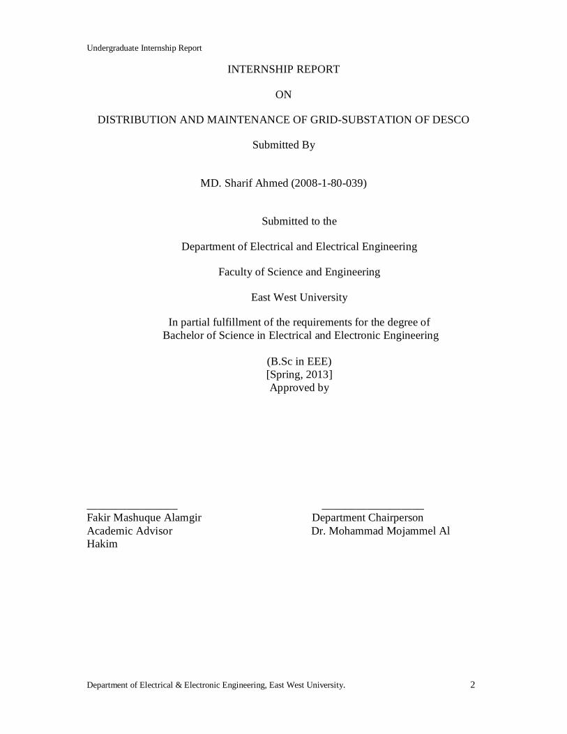
EAST WEST UNIVERSITY INTERNSHIP REPORT
ON
DISTRIBUTION AND MAINTENANCE OF GRID-SUBSTATION OF DESCO
Submitted By
MD. Sharif Ahmed (2008-1-80-039)
Submitted to the
Department of Electrical and Electrical Engineering
Faculty of Science and Engineering
East West University
In partial fulfillment of the requirements for the degree of Bachelor of Science in Electrical and Electronic Engineering
(B.Sc in EEE)
[Spring, 2013]
Undergraduate Internship Report
Department of Electrical & Electronic Engineering, East West University. 2
INTERNSHIP REPORT
ON
DISTRIBUTION AND MAINTENANCE OF GRID-SUBSTATION OF DESCO
Submitted By
MD. Sharif Ahmed (2008-1-80-039)
Submitted to the
Department of Electrical and Electrical Engineering
Faculty of Science and Engineering
East West University
In partial fulfillment of the requirements for the degree of Bachelor of Science in Electrical and Electronic Engineering
(B.Sc in EEE) [Spring, 2013] Approved by
________________ __________________ Fakir Mashuque Alamgir Department Chairperson Academic Advisor Dr. Mohammad Mojammel Al Hakim
Undergraduate Internship Report
Department of Electrical & Electronic Engineering, East West University. 3
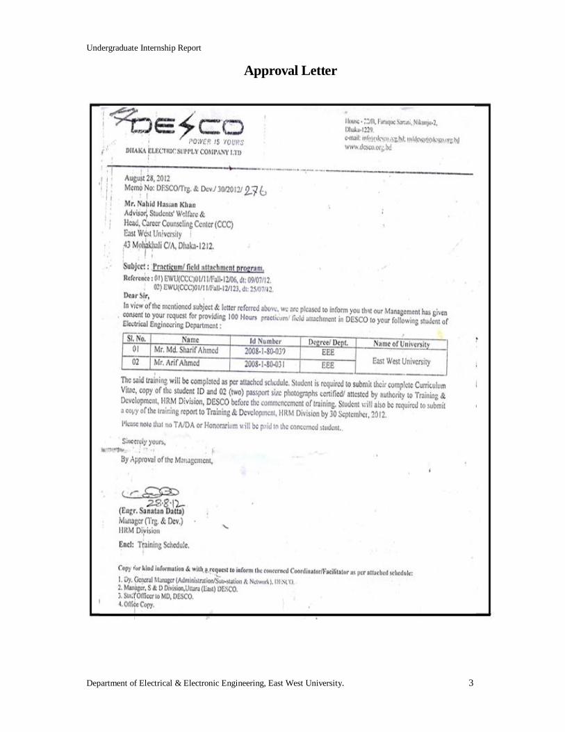
Approval Letter
Undergraduate Internship Report
Department of Electrical & Electronic Engineering, East West University. 4
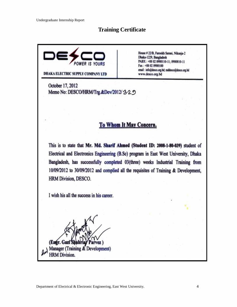
Training Certificate
Undergraduate Internship Report
Department of Electrical & Electronic Engineering, East West University. 5
Acknowledgement
First of all I would like to thank Engr. Gazi Shariar Parvez, Manager, training & development
Md. Taquiue Abdullah, Manager Administrating of DESCO, for allowing me to do internship
and work with them.
I would also like to thank my academic advisor Fakir Mashuque Alamgir, Lecturer,
Department of Electrical & Electronic Engineering, East West University, Bangladesh.
Then I would also like to mention the name of Dr. Mohammad Mojammel Al Hakim,
Chairperson & Professor of the Department of Electrical & Electronic Engineering. I am also
grateful to all our teachers and friends for their cooperation and encouragement throughout
my whole academic life at East West University. I would also like to thank Dr. Kazi Mujibur
Rahaman, Adjunct faculty at East West University. I would like to thank some persons who
had given me the opportunity to collect some information for my report and also helped me to
understand many related matters and gave me their precious time more than once. They are;
Engr. Md. Shahin Ibne Rafiq. Deputy Manager (Trang. & Div.), Md. Rasudur Rahnan DGM
(admin), S.M. Hasibul Islam, Jr. Assistant Manager (Uttara grid-substation), Engr.
Mohammad Kamruzzama, Manager (Uttara S.& D. Division) and Md. Rezaul Karim, Jr.
Assistant Manager (Kafrul substation).
Finally, I would to thank all my teachers, student and staffs of Department of Electrical and
Electronic Engineering at East West University and all of my family members and friends
whose names are not mentioned here.
Undergraduate Internship Report
Department of Electrical & Electronic Engineering, East West University. 6
Executive Summary
The power sector of Bangladesh have faced numerous problems characterized by lack of
supply capacity, frequent power cuts, unacceptable quality of supply and poor financial and
operational performance of the sector entities. There have been a number of reforms in the
power sector in Bangladesh since the independence. But most of these reforms failed to bring
the desired outcome in the power sector. Among the three main components of the power
system, recent reform activities were centered on generation and transmission. The most
pressing problems in the power sector have been with the distribution system, which is
characterized by heavy system loss and poor collection performance. However, the
distribution system seldom gets the priority in the reform initiatives.
To solve these problems, Government of Bangladesh has taken an initiative to unbundle the
power sector in the form of The Private Limited Companies. This report is based on my
internship activities which I have done at DESCO (Dhaka Electric Supply Company
Limited). This report focuses on the operation of DESCO, their vision, supply capacity,
financial condition, distribution of electricity and future planning. The Dhaka electric supply
company was created as a distribution company in 1996 under the companies act 1994 as a
public limited company with an authorized capital of TK. 5 million. At present, DESCO is
one of the main power distribution companies in Bangladesh. In total 75% shares of DESCO
are owned by Bangladesh Government and rests of the 25% shares are owned by Chairman
of DESCO and other shareholders.
Internship is such an opportunity to learn those activities that are related to our real
engineering world. During my internship period, I have been able to gather some knowledge
on grid-substation, transformer and their maintenance and the power factor improvement
which are closely related to my study materials. I have also observed their administrative
activities of control room; complain room operation, IT (Information & Technology) and one
point operation which will surely help me to visualize the effectiveness in my practical life.

Undergraduate Internship Report
Department of Electrical & Electronic Engineering, East West University. 7
Internship Schedule
Day Time duration Topics Mentor
Monday 10.09.2012
9 am to1.30 pm, 2.30pm to 5.00 pm
Introduction, service area, organization
Engr. MD.Shahin Ibne Rafiq Deputy Manager
Tuesday 11.09.2012
9 am to1.30 pm, 2.30pm to 5.00 pm
Administrative activities MD. Rashidur Rahman DGM (admin)
Wednesday 12.09.2012
9 am to1.30 pm, 2.30pm to 5.00 pm
Grid-substation, single line diagram and equipment’s.
S.M. Hasibul Islam Jr. Assistant Manager.
Friday 14.09.2012
9 am to1.30 pm, 3.00 pm to 5.00 pm
Transformer, its principal and component.
Suman Datta Jr. Assistant Manager.
Saturday 15.09.2012
9 am to1.30 pm, 3.00 pm to 5.00 pm
Transformer component, Protection and energy losses.
Md. Tamiz Uddin Jr. Assistant Manager.
Monday 17.09.2012
9 am to1.30 pm, 2.30pm to 5.00 pm
Substation auxiliary x-former and circuit breaker
S.M. Hasibul Islam Jr. Assistant Manager.
Tuesday 18.09.2012
9 am to1.30 pm, 2.30pm to 5.00 pm
Commercial activities. Engr.Mohammad Kamruzzaman Manager.
Wednesday 19.09.2012
9 am to1.30 pm, 2.30pm to 5.00 pm
Technical operation. Engr.Mohammad Kamruzzaman Manager.
Friday 21.09.2012
9 am to1.30 pm, 3.00 pm to 5.00 pm
VCB,PT,CT,LA MD. Mahumudur Rahman Jr. Assistant Manager.
Saturday 22.09.2012
9 am to1.30 pm, 3.00pm to 5.00 pm
Isolator, bus bar and Battery and battery charger.
MD. Mahumudur Rahman Jr. Assistant Manager.
Monday 24.09.2012
9 am to1.30 pm, 2.30pm to 5.00 pm
Maintenance and protection of Substation
Engr. Md Golam Mowla Deputy Manager.
Tuesday 25.09.2012
9 am to1.30 pm, 2.30pm to 5.00 pm
Transformer, fault detection and repairing.
MD. Monraj Khan Jr. Assistant Manager.
Wednesday 26.09.2012
9 am to1.30 pm, 2.30pm to 5.00 pm
Power factor monitoring and upgrading.
Md.Rezaul Karim Jr. Assistant Manager.
Friday 28.09.2012
9 am to1.30 pm, 3.00 pm to 5.00 pm
Control room activities. Md.Rezaul Karim Jr. Assistant Manager.
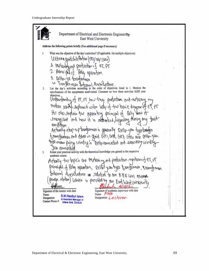
Monday 01.10.2012
9 am to1.30 pm, 2.30pm to 5.00 pm
Principal of relay operation and delta-y x-former.
S.M. Hasibul Islam Jr. Assistant Manager.
Total internship hours=103 hours
Undergraduate Internship Report
Department of Electrical & Electronic Engineering, East West University. 8
Table of Content
Approval Letter ..................................................................................................................3
Training Certificate ............................................................................................................4
Acknowledgement ...............................................................................................................5
Executive Summary ............................................................................................................6
Internship Schedule ............................................................................................................7
Table of Content .................................................................................................................8
List of Figures ................................................................................................................... 10
Chapter 1
Introduction ...................................................................................................................... 11
1.1 Background of DESCO ........................................................................................... 11
1.2 Organization and Service area of DESCO ................................................................ 11
1.3 Technical Operation ................................................................................................ 11
Chapter 2 Operation of Grid-Substation .......................................................................................... 13
2.1 Grid- Substation ...................................................................................................... 13
2.2 General Equipment .................................................................................................. 16
2.3 Operational Equipment ............................................................................................ 16
2.3.1 Transformer at DESCO ........................................................................................... 16
2.3.2 Transformer Specification ....................................................................................... 17
2.3.3 Transformer Component .......................................................................................... 18
2.3.4 Losses in Transformer ............................................................................................. 21
2.3.5 Protection Systems for transformer .......................................................................... 21
2.4 Auxiliary Transformers ........................................................................................... 22
2.5 Circuit Breaker ........................................................................................................ 22
2.5.1 SF6 Gas Circuit Breakers ........................................................................................ 22
2.5.2 Vacuum Circuit Breakers ......................................................................................... 23
2.6 Potential Transformers ............................................................................................ 23
2.7 Current Transformers .............................................................................................. 24
2.8 Lighting Arresters.................................................................................................... 24
2.9 Isolators ................................................................................................................... 25
2.10 Bus Bars and Bus Coupler ....................................................................................... 26
2.11 Battery and Battery Charger .................................................................................... 27
Chapter 3
Maintenance and Protection of Grid-Substation ............................................................. 28
3.1 Maintenance and Inspection of Substation ............................................................... 28
3.2 Transformer Maintenance ........................................................................................ 29
3.3 Transformer Fault Detection and Repairing ............................................................. 30
3.4 Power Factor Monitoring & Upgrading ................................................................... 31
3.5 Control Room Activity ............................................................................................ 31
3.6 Incoming Panels or Lines ........................................................................................ 32
3.7 The 33 KV Transformer Control Panels ................................................................... 33
3.8 Outgoing Feeders .................................................................................................... 35

Undergraduate Internship Report
Department of Electrical & Electronic Engineering, East West University. 9
Chapter 4 Conclusion ......................................................................................................................... 37
4.1 Discussion ............................................................................................................... 37
4.2 Problems ................................................................................................................. 37
4.3 Recommendation ............................................................ Error! Bookmark not defined. References ......................................................................................................................... 39
Appendix ........................................................................................................................... 40
Undergraduate Internship Report
Department of Electrical & Electronic Engineering, East West University. 10
List of Figures
Figure 2.1: Uttara grid-substation with bus-1, bus-2, insolator, PT and bus coupler. ..... 14
Figure 2.2: 132KV incoming source from Tongi and wave trap, PT and L.A. .............. 14
Figure 2.3: Single line diagram of Uttara grid-substation (132/33/11KV). .................... 15
Figure 2.4: 132/33 KV Power transformer (GT1) at Uttara grid-substation . ................ 16
Figure 2.5: 33/11KV power transformer (GT4) at Uttara grid-substation...................... 17
Figure 2.6: Nameplate of transformer main control box. .............................................. 17
Figure 2.7: Main tank with primary & secondary winding. ........................................... 18
Figure 2.8: Conservator tank at Uttara grid-substation.................................................. 19
Figure 2.9: Action of buchholz relay at Uttara grid-substation. ..................................... 19
Figure 2.10: Winding temperature and oil temperature indicator. ................................. 20
Figure 2.11: Tap changing mechanism ......................................................................... 20
Figure 2.12: Transformer breathing system (silica gel) used at DESCO. ...................... 21
Figure 2.13: Auxiliary transformer at Uttara grid-substation. ....................................... 22
Figure 2.14: SF6 gas circuit breakers at Uttara grid-substation. .................................... 23
Figure 2.15: Potential transformer at Uttara grid-substation. ........................................ 24
Figure 2.16: Current transformer at Uttara grid-substation. .......................................... 24
Figure 2.17: Lighting Arrester and GT-2 at Uttara grid-substation. .............................. 25
Figure 2.18: Lighting arrester indicator at Uttara grid-substation. ................................. 25
Figure 2.19: Line isolator at Uttara grid-substation. ..................................................... 26
Figure 2.20: 132 KV bus bars and bus coupler at Uttara grid-substation. ...................... 27
Figure 2.21: Battery back up system of 132/33/11KV Uttara grid-substation. .............. 27
Figure 3.1: Single line diagram of Kafrul (Mirpur) 33/11 KV substation. ..................... 28
Figure 3.2: Maintenance of Kafrul (Mirpur) 33/11 KV substation. ............................... 29
Figure 3.3: Transformer maintenances at Uttara grid-substation ................................... 29
Figure 3.4: The 11/.415KV distribution transformer..................................................... 30
Figure 3.5: PF dependence on the amplitude of KVA. .................................................. 31
Figure 3.6: Control room at Kafrul substation (33/11KV). .......................................... 32
Figure 3.7: The relay protection on 33KV incoming line at Kafrul substation. ............. 33
Figure 3.8: The digital relay protection on 33KV transformer panel. ............................ 34
Figure 3.9: The relay protection on 33KV transformer panel at Kafrul substation. ....... 35
Undergraduate Internship Report
Department of Electrical & Electronic Engineering, East West University. 11
Chapter 1 Introduction 1.1 Background of DESCO Dhaka Electric Supply Company Ltd (DESCO) was created as a distribution company on
November, 1996, under the company act 1994 as a Public Limited Company with an
authorized capital of Tk. 5.00 billion, due to improve power sector, to provide better service
and to improve revenue collection specially in Dhaka city. However, the operational activities
are at DESCO’s field level commenced on September 24, 1998 [1].
1.2 Organization and Service area of DESCO The company is run by a small management team headed by the Managing Director under the
guidance of a Board of Directors and six numbers of sales and distribution division and above
forty numbers of grid-substations. DESCO always visualizes running the system efficiently
and economically keeping minimum overhead cost with minimum number of skilled
manpower. The area is about 220 square kilometers comprises the areas bounded by the
Mirpur Road, Agargaon Road, Rokeya Sarani, Progati Sarani, New Airport Road,
Mymenshing Road, Mohakhali Jhee, Rampura Jheel connected with Balu River in the south ,
Balu River in the east and Turag River in the west and areas under Tongi Pourashava in the
north. It may be mentioned that “Purbachal Model Town” a Rajuk project, situated on the
east side of Balu River, adjacent to Dakkhinkhan area, has been decided to be included under
DESCO [1].
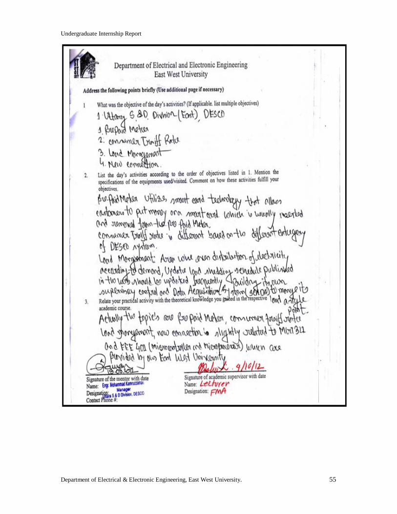
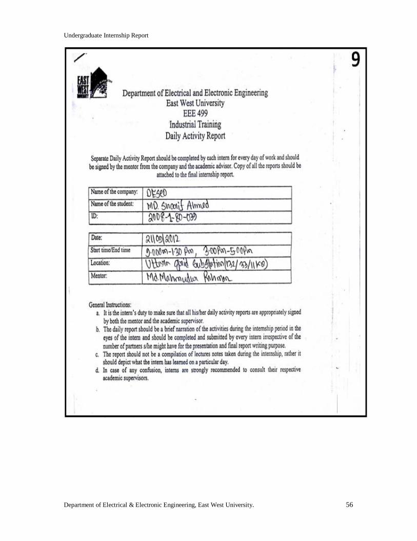
1.3 Technical Operation On September 19, 2012, I went to the Uttara sales & distribution division of DESCO to
understand technical operation, where Engr. Mohammad Kamruzzaman (Manager, Uttara
sales & distribution division, DESCO) explained me about the system operations of sales &
distribution, Pre-paid meter, consumer tariff rate, load management and new connection.
Prepaid meter utilizes smart card technology that allows customers to put money on a smart
card which is usually inserted and removed from the prepaid meter. The meter reads a chip in
the card and ensures that only the amount of electricity that has been paid for be available to
the customer. Customers can re-charge their smart cards of DESCO at vending stations. The
Undergraduate Internship Report
Department of Electrical & Electronic Engineering, East West University. 12
introduction of prepaid meters has helped to improve revenue collections as well as to reduce
system loss.
There are ten types of consumer tariff rates. These are as follows:
(a)A-Residential, (b)B-Irrigation, (c)C-Small industry, (d)D-Non-resident,(e)E-commercial
(f)F-11KV,(g)G-33/132KV(DPDC),(h)H-HT,(i)I-(I-1,I-2,I-3,I-4,I-5,I-6)-utility,(j)J-street
light.
Undergraduate Internship Report
Department of Electrical & Electronic Engineering, East West University. 13
Chapter 2 Operation of Grid-Substation
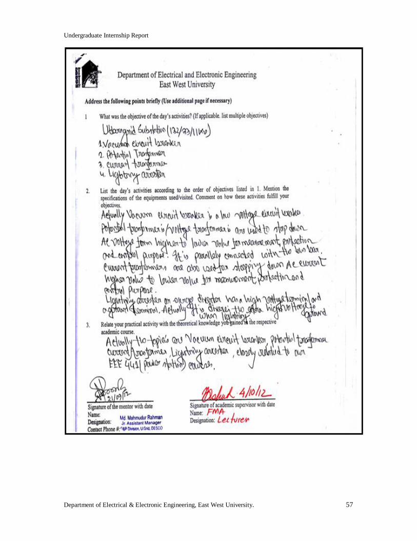
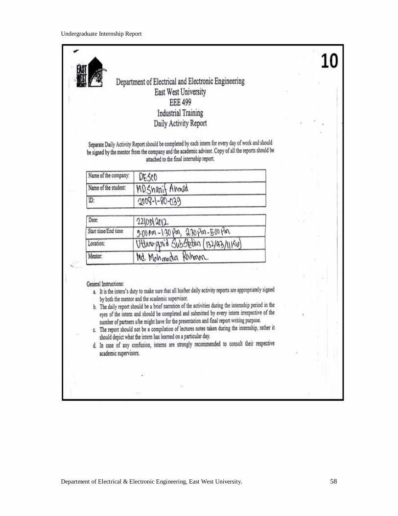
2.1 Grid- Substation During my internship period at DESCO, I have visited at four grid-substations. On September
12, I went to the Uttara grid-substation where Jr. Assistant Manager, S.M.Hasibul Islam,
explained me about the basic definition and the working principal of grid-substation, single
line diagram, general equipment and their operation. Actually super grid-substation voltage
level is about 230/132/33KV, grid-substation voltage level is about 132/33/11KV, and
substation voltage level is about 33/11KV. But grid-substation is an interrelated network for
delivering electricity from suppliers to consumers. The DESCO has no power plant.
Therefore, they purchase power and transmitted from Power Development Board (PDB) via
Power Grid Company of Bangladesh (PGCB) at different places of Dhaka city. A grid-
substation or substation transforms voltages from high to low or low to high by using power
transformers. A substation that has a step-up power transformer increases the voltage while
decreasing the current, while a step-down distribution transformer decreases the voltage
while increasing the current for domestic and commercial uses of electricity.
At DESCO, there are above forty numbers of grid-substations, but during my internship
period, I have visited only four grid-substations due to lack of time. These are as follows:
Uttara grid-substation (132KV/33KV/11KV).
Kafrul (Mirpur) substation (33KV/11KV).
Uttara East substation (33KV/11KV).
Nikunja substation (33KV/11 KV).
At Uttara grid-substation, there are two incoming sources from Mirpur and Tongi grid.
Undergraduate Internship Report
Department of Electrical & Electronic Engineering, East West University. 14
132KV bus-1, 132KV bus-2, bus PT-1 (potential transformer), bus PT-2 (potential
transformer), 132KV bus coupler and the insulator of Uttara grid-substation are shown in
figure (2.1).
Figure 2.1: Uttara grid-substation with bus-1, bus-2, insulator, PT and bus coupler.
The wave trap, potential transformer (PT), lighting arrester (L.A) and 132KV incoming source
from Tongi grid of Uttara grid-substation are shown in figure (2.2).
Figure 2.2: 132KV incoming source from Tongi grid, wave trap, PT and L.A.
Actually single line diagram is the basic configuration to understand the basic operation of
grid-substation. In figure (2.3), it is shown that how 132KV incoming sources are connected
to the Uttara urid-substation and then how it transforms from 132KV to 33KV. Also 33KV
transforms to 11KV. Initially 132KV incoming sources from Tongi grid and Mirpur grid are
connected to Uttara grid-substation via UG/OHL (UG means underground and OHL means

Undergraduate Internship Report
Department of Electrical & Electronic Engineering, East West University. 15
overhead line), then safety equipment L.A. (Lighting Arrester), potential transformer (PT),
wave trap, isolator, current transformer (CT), SF6 gas circuit breaker are connected to 132KV
bus-1. Then 132KV bus coupling is used to run or to keep active both 132KV bus-1 and
132KV bus-2. Then again PT, isolator, CT, L.A. and grid-transformer-1 which transforms the
voltages from 132KV to 33KV. Subsequently 33KV is also connected with 33KV bus via
SF6 gas circuit breaker. Here also 33KV bus coupling is used to run both 33KV bus-1 and
33KV bus-2. Last of all VCB (Vacuum Circuit Breaker) is also connected to 33KV bus and
then grid-transformer-3, which transforms the voltages from 33KV to 11 KV. Subsequently
11KV is also connected with 11KV bus via VCB and then active eight numbers of 11KV
outgoing feeders are connected to different sectors of Uttara. The single line diagram of
Uttara grid-substation is given in figure (2.3).
Figure 2.3: Single line diagram of Uttara grid-substation (132/33/11KV).
In our country, the voltage transmissions are 400KV, 230KV, 132KV respectively. But at
DESCO the step down transmission voltages are 132KV to 33KV, 33KV to 11KV and 11KV to
415V. At Uttara grid-substation the step down voltage is 132/33/11 KV.
Undergraduate Internship Report
Department of Electrical & Electronic Engineering, East West University. 16
2.2 General Equipment There are various equipment at Uttara grid-substation which I have observed and acquired
knowledge such as power transformer, switchgear/circuit breaker, SF6 gas circuit breaker,
vacuum circuit breaker, current transformer, potential transformer, isolator, line isolator,
earth switch, wave trap, lightening arrester, auxiliary transformer, bus bar (main bus bar and
reserve bus bar), battery and battery charger, control relay panel, ac & dc distribution panels
and voltage regulator etc.
2.3 Operational Equipment 2.3.1 Transformer at DESCO
Power Transformer: During my internship period at Uttara grid-substation (132/33/11KV), I
have acquired knowledge about transformer. Actually a transformer is a device which transforms
electric power from one circuit to another circuit without changing in frequency. The electric
power of transformer is created by electromagnetic induction between the windings or circuits.
Depending upon the size of the windings, values of voltage and current are changed from
primary (source) to secondary (load) with constant frequency. At DESCO, I have observed
power transformer to transform power from 132 KV to 33 KV and 33KV to 11KV where 132
KV is supplied by PGCB. Most of the power transformers are made by Energy Pack and
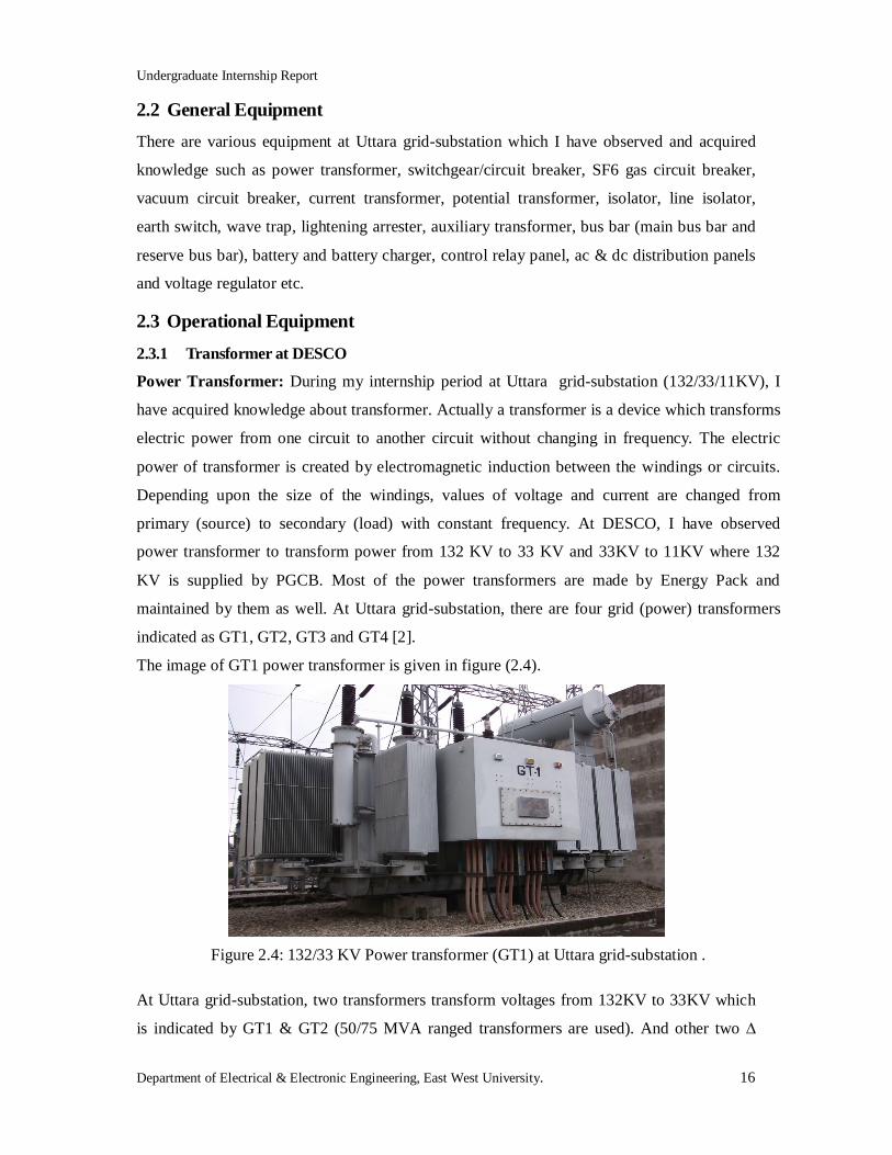
maintained by them as well. At Uttara grid-substation, there are four grid (power) transformers
indicated as GT1, GT2, GT3 and GT4 [2].
The image of GT1 power transformer is given in figure (2.4).
Figure 2.4: 132/33 KV Power transformer (GT1) at Uttara grid-substation .
At Uttara grid-substation, two transformers transform voltages from 132KV to 33KV which
is indicated by GT1 & GT2 (50/75 MVA ranged transformers are used). And other two ∆
Undergraduate Internship Report
Department of Electrical & Electronic Engineering, East West University. 17
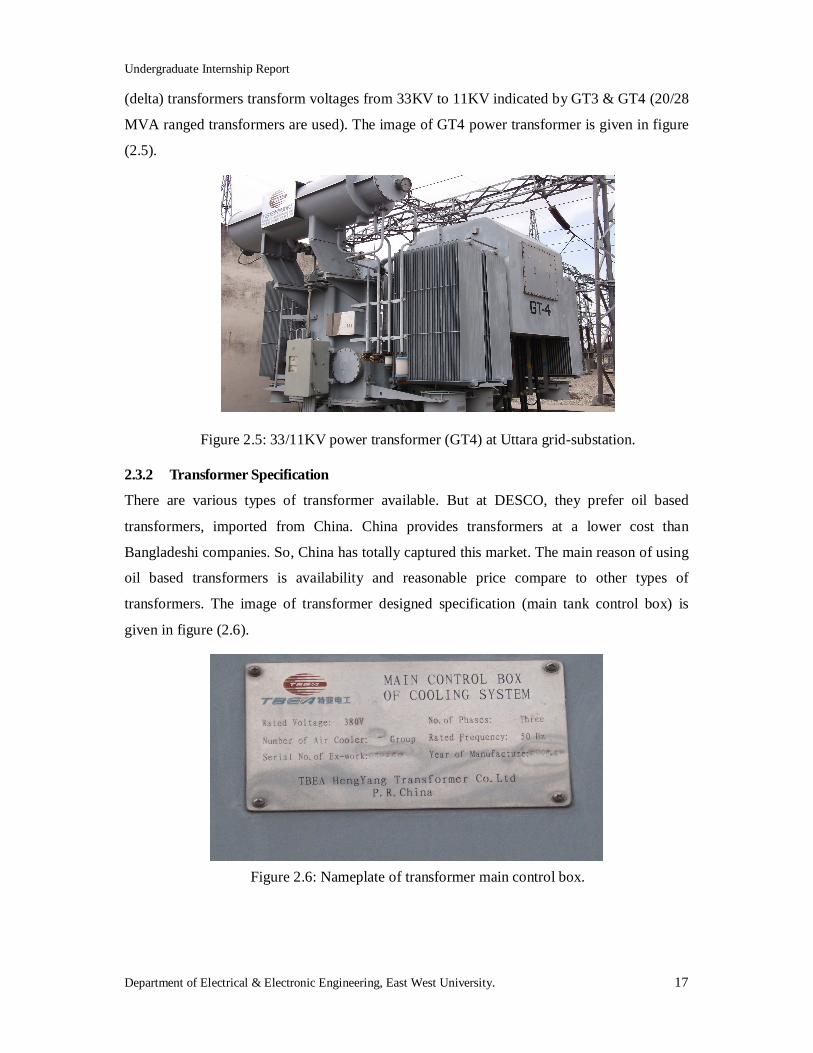
(delta) transformers transform voltages from 33KV to 11KV indicated by GT3 & GT4 (20/28
MVA ranged transformers are used). The image of GT4 power transformer is given in figure
(2.5).
Figure 2.5: 33/11KV power transformer (GT4) at Uttara grid-substation.
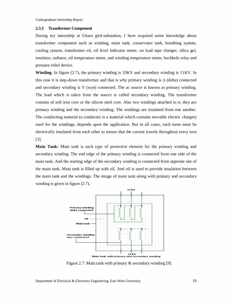
2.3.2 Transformer Specification
There are various types of transformer available. But at DESCO, they prefer oil based
transformers, imported from China. China provides transformers at a lower cost than
Bangladeshi companies. So, China has totally captured this market. The main reason of using
oil based transformers is availability and reasonable price compare to other types of
transformers. The image of transformer designed specification (main tank control box) is
given in figure (2.6).
Figure 2.6: Nameplate of transformer main control box.
Undergraduate Internship Report
Department of Electrical & Electronic Engineering, East West University. 18
2.3.3 Transformer Component
During my internship at Uttara gird-substation, I have acquired some knowledge about
transformer component such as winding, main tank, conservator tank, breathing system,
cooling system, transformer oil, oil level indicator meter, on load tape changer, silica gel,
insulator, radiator, oil temperature meter, and winding temperature meter, buchholz relay and
pressure relief device.
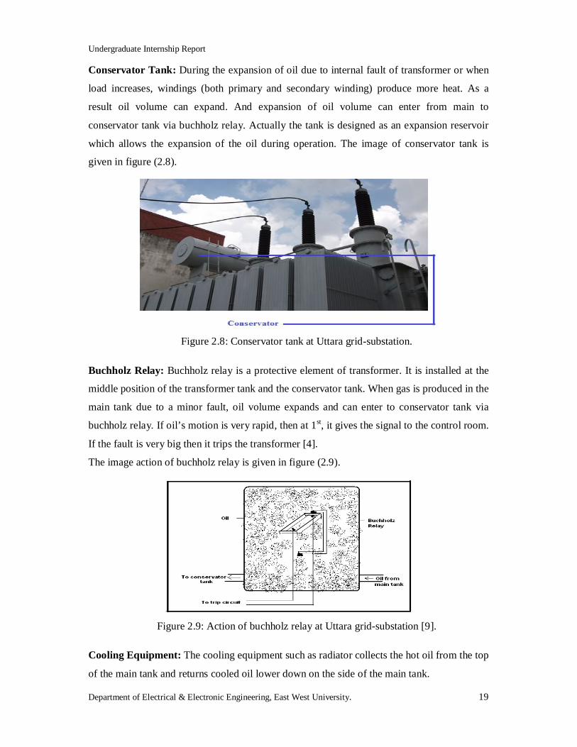
Winding: In figure (2.7), the primary winding is 33KV and secondary winding is 11KV. In
this case it is step-down transformer and that is why primary winding is ∆ (delta) connected
and secondary winding is Y (wye) connected. The ac source is known as primary winding.
The load which is taken from the source is called secondary winding. The transformer
consists of soft iron core or the silicon steel core. Also two windings attached to it, they are
primary winding and the secondary winding. The windings are insulated from one another.
The conducting material (a conductor is a material which contains movable electric charges)
used for the windings, depends upon the application. But in all cases, each turns must be
electrically insulated from each other to ensure that the current travels throughout every turn
[3].
Main Tank: Main tank is such type of protective element for the primary winding and
secondary winding. The end edge of the primary winding is connected from one side of the
main tank. And the starting edge of the secondary winding is connected from opposite site of
the main tank. Main tank is filled up with oil. And oil is used to provide insulation between
the main tank and the windings. The image of main tank along with primary and secondary
winding is given in figure (2.7).
Figure 2.7: Main tank with primary & secondary winding [9].
Undergraduate Internship Report
Department of Electrical & Electronic Engineering, East West University. 19
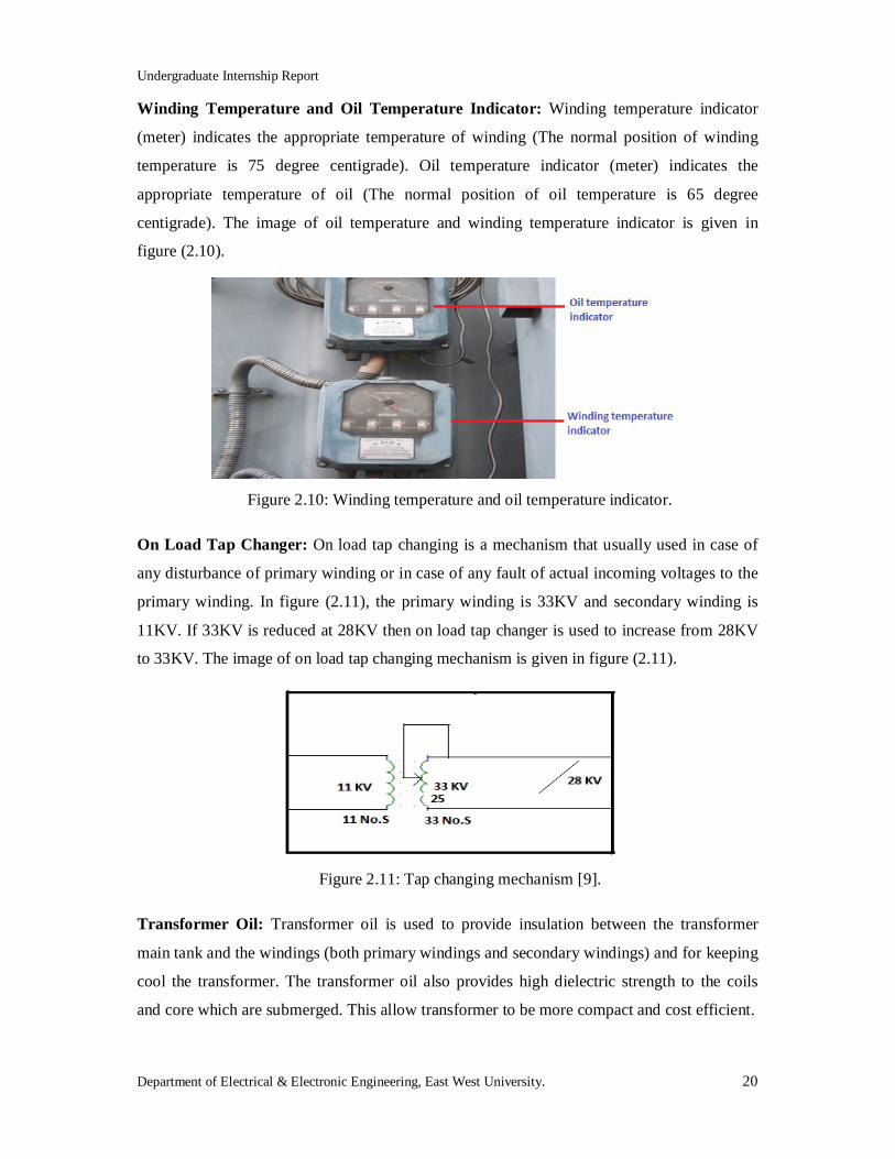
Conservator Tank: During the expansion of oil due to internal fault of transformer or when
load increases, windings (both primary and secondary winding) produce more heat. As a
result oil volume can expand. And expansion of oil volume can enter from main to
conservator tank via buchholz relay. Actually the tank is designed as an expansion reservoir
which allows the expansion of the oil during operation. The image of conservator tank is
given in figure (2.8).
Figure 2.8: Conservator tank at Uttara grid-substation.
Buchholz Relay: Buchholz relay is a protective element of transformer. It is installed at the
middle position of the transformer tank and the conservator tank. When gas is produced in the
main tank due to a minor fault, oil volume expands and can enter to conservator tank via
buchholz relay. If oil’s motion is very rapid, then at 1st, it gives the signal to the control room.
If the fault is very big then it trips the transformer [4].
The image action of buchholz relay is given in figure (2.9).
Figure 2.9: Action of buchholz relay at Uttara grid-substation [9].
Cooling Equipment: The cooling equipment such as radiator collects the hot oil from the top
of the main tank and returns cooled oil lower down on the side of the main tank.
Undergraduate Internship Report
Department of Electrical & Electronic Engineering, East West University. 20
Winding Temperature and Oil Temperature Indicator: Winding temperature indicator
(meter) indicates the appropriate temperature of winding (The normal position of winding
temperature is 75 degree centigrade). Oil temperature indicator (meter) indicates the
appropriate temperature of oil (The normal position of oil temperature is 65 degree
centigrade). The image of oil temperature and winding temperature indicator is given in
figure (2.10).
Figure 2.10: Winding temperature and oil temperature indicator.
On Load Tap Changer: On load tap changing is a mechanism that usually used in case of
any disturbance of primary winding or in case of any fault of actual incoming voltages to the
primary winding. In figure (2.11), the primary winding is 33KV and secondary winding is
11KV. If 33KV is reduced at 28KV then on load tap changer is used to increase from 28KV
to 33KV. The image of on load tap changing mechanism is given in figure (2.11).
Figure 2.11: Tap changing mechanism [9].
Transformer Oil: Transformer oil is used to provide insulation between the transformer
main tank and the windings (both primary windings and secondary windings) and for keeping
cool the transformer. The transformer oil also provides high dielectric strength to the coils
and core which are submerged. This allow transformer to be more compact and cost efficient.
Undergraduate Internship Report
Department of Electrical & Electronic Engineering, East West University. 21
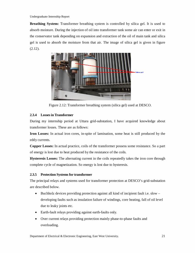
Breathing System: Transformer breathing system is controlled by silica gel. It is used to
absorb moisture. During the injection of oil into transformer tank some air can enter or exit in
the conservator tank depending on expansion and extraction of the oil of main tank and silica
gel is used to absorb the moisture from that air. The image of silica gel is given in figure
(2.12).
Figure 2.12: Transformer breathing system (silica gel) used at DESCO.
2.3.4 Losses in Transformer
During my internship period at Uttara grid-substation, I have acquired knowledge about
transformer losses. These are as follows:
Iron Losses: In actual iron cores, in-spite of lamination, some heat is still produced by the
eddy currents.
Copper Losses: In actual practice, coils of the transformer possess some resistance. So a part
of energy is lost due to heat produced by the resistance of the coils.
Hysteresis Losses: The alternating current in the coils repeatedly takes the iron core through
complete cycle of magnetization. So energy is lost due to hysteresis.
2.3.5 Protection Systems for transformer
The principal relays and systems used for transformer protection at DESCO’s grid-substation
are described below.
Buchholz devices providing protection against all kind of incipient fault i.e. slow –
developing faults such as insulation failure of windings, core heating, fall of oil level
due to leaky joints etc.
Earth-fault relays providing against earth-faults only.
Over current relays providing protection mainly phase-to-phase faults and
overloading.
Undergraduate Internship Report
Department of Electrical & Electronic Engineering, East West University. 22
Differential system (or circulating current system) providing protection against both
earth and phase fault.
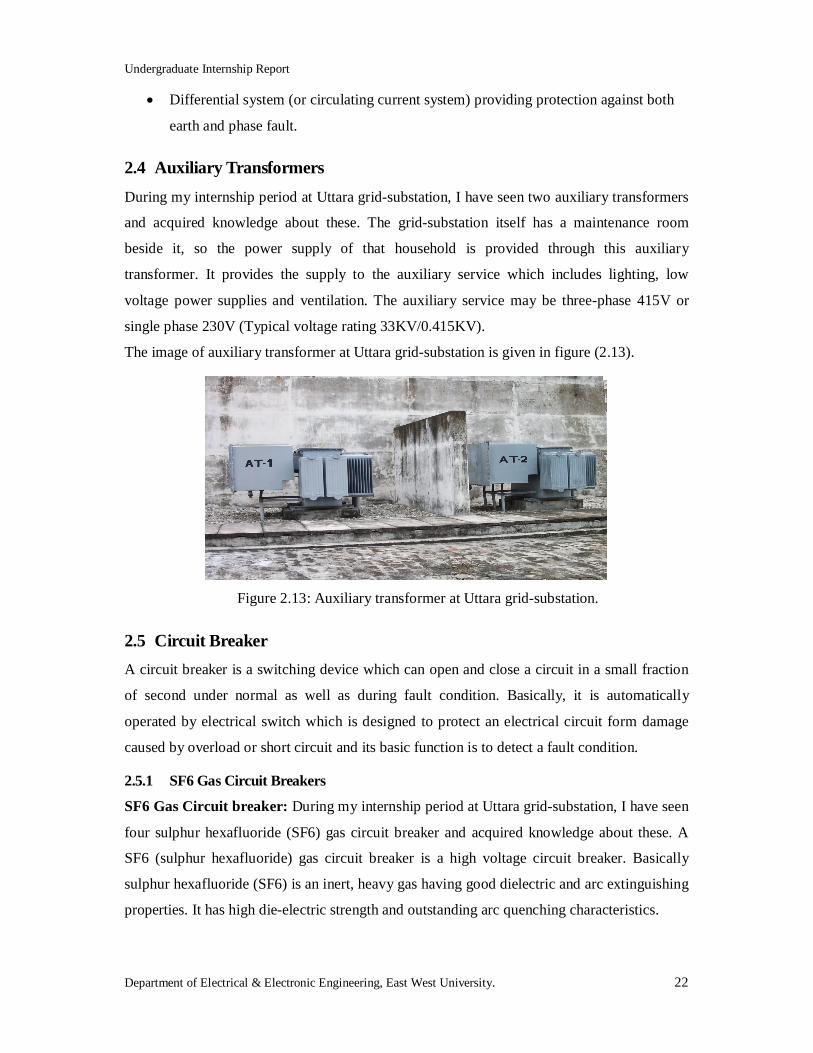
2.4 Auxiliary Transformers During my internship period at Uttara grid-substation, I have seen two auxiliary transformers
and acquired knowledge about these. The grid-substation itself has a maintenance room
beside it, so the power supply of that household is provided through this auxiliary
transformer. It provides the supply to the auxiliary service which includes lighting, low
voltage power supplies and ventilation. The auxiliary service may be three-phase 415V or
single phase 230V (Typical voltage rating 33KV/0.415KV).
The image of auxiliary transformer at Uttara grid-substation is given in figure (2.13).
Figure 2.13: Auxiliary transformer at Uttara grid-substation.
2.5 Circuit Breaker A circuit breaker is a switching device which can open and close a circuit in a small fraction
of second under normal as well as during fault condition. Basically, it is automatically
operated by electrical switch which is designed to protect an electrical circuit form damage
caused by overload or short circuit and its basic function is to detect a fault condition.
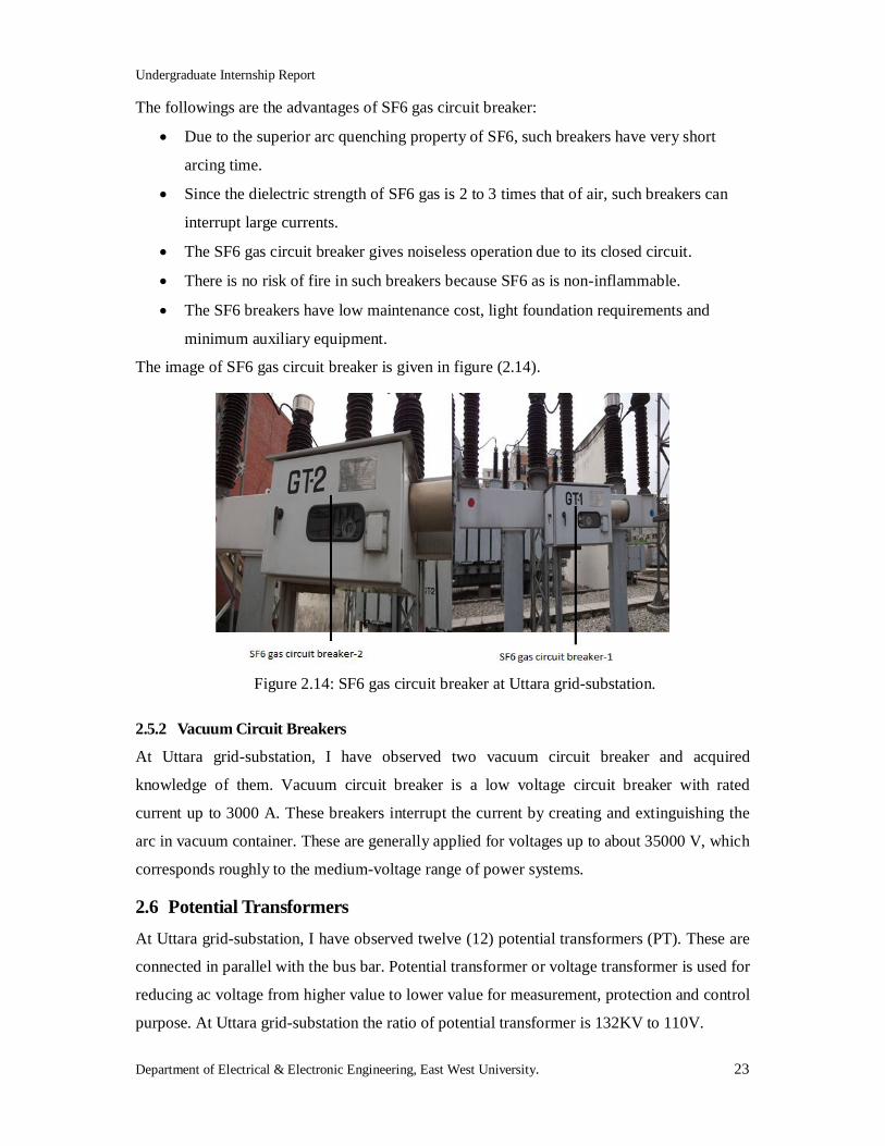
2.5.1 SF6 Gas Circuit Breakers
SF6 Gas Circuit breaker: During my internship period at Uttara grid-substation, I have seen
four sulphur hexafluoride (SF6) gas circuit breaker and acquired knowledge about these. A
SF6 (sulphur hexafluoride) gas circuit breaker is a high voltage circuit breaker. Basically
sulphur hexafluoride (SF6) is an inert, heavy gas having good dielectric and arc extinguishing
properties. It has high die-electric strength and outstanding arc quenching characteristics.
Undergraduate Internship Report
Department of Electrical & Electronic Engineering, East West University. 23
The followings are the advantages of SF6 gas circuit breaker:
Due to the superior arc quenching property of SF6, such breakers have very short
arcing time.
Since the dielectric strength of SF6 gas is 2 to 3 times that of air, such breakers can
interrupt large currents.
The SF6 gas circuit breaker gives noiseless operation due to its closed circuit.
There is no risk of fire in such breakers because SF6 as is non-inflammable.
The SF6 breakers have low maintenance cost, light foundation requirements and
minimum auxiliary equipment.
The image of SF6 gas circuit breaker is given in figure (2.14).
Figure 2.14: SF6 gas circuit breaker at Uttara grid-substation.
2.5.2 Vacuum Circuit Breakers
At Uttara grid-substation, I have observed two vacuum circuit breaker and acquired
knowledge of them. Vacuum circuit breaker is a low voltage circuit breaker with rated
current up to 3000 A. These breakers interrupt the current by creating and extinguishing the
arc in vacuum container. These are generally applied for voltages up to about 35000 V, which
corresponds roughly to the medium-voltage range of power systems.
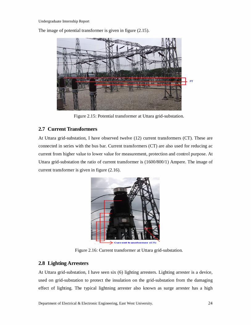
2.6 Potential Transformers At Uttara grid-substation, I have observed twelve (12) potential transformers (PT). These are
connected in parallel with the bus bar. Potential transformer or voltage transformer is used for
reducing ac voltage from higher value to lower value for measurement, protection and control
purpose. At Uttara grid-substation the ratio of potential transformer is 132KV to 110V.
Undergraduate Internship Report
Department of Electrical & Electronic Engineering, East West University. 24
The image of potential transformer is given in figure (2.15).
Figure 2.15: Potential transformer at Uttara grid-substation.
2.7 Current Transformers At Uttara grid-substation, I have observed twelve (12) current transformers (CT). These are
connected in series with the bus bar. Current transformers (CT) are also used for reducing ac
current from higher value to lower value for measurement, protection and control purpose. At
Uttara grid-substation the ratio of current transformer is (1600/800/1) Ampere. The image of
current transformer is given in figure (2.16).
Figure 2.16: Current transformer at Uttara grid-substation.
2.8 Lighting Arresters At Uttara grid-substation, I have seen six (6) lighting arresters. Lighting arrester is a device,
used on grid-substation to protect the insulation on the grid-substation from the damaging
effect of lighting. The typical lightning arrester also known as surge arrester has a high
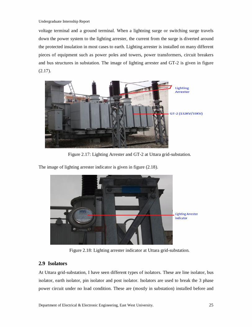
Undergraduate Internship Report
Department of Electrical & Electronic Engineering, East West University. 25
voltage terminal and a ground terminal. When a lightning surge or switching surge travels
down the power system to the lighting arrester, the current from the surge is diverted around
the protected insulation in most cases to earth. Lighting arrester is installed on many different
pieces of equipment such as power poles and towers, power transformers, circuit breakers
and bus structures in substation. The image of lighting arrester and GT-2 is given in figure
(2.17).
Figure 2.17: Lighting Arrester and GT-2 at Uttara grid-substation.
The image of lighting arrester indicator is given in figure (2.18).
Figure 2.18: Lighting arrester indicator at Uttara grid-substation.
2.9 Isolators At Uttara grid-substation, I have seen different types of isolators. These are line isolator, bus
isolator, earth isolator, pin isolator and post isolator. Isolators are used to break the 3 phase
power circuit under no load condition. These are (mostly in substation) installed before and
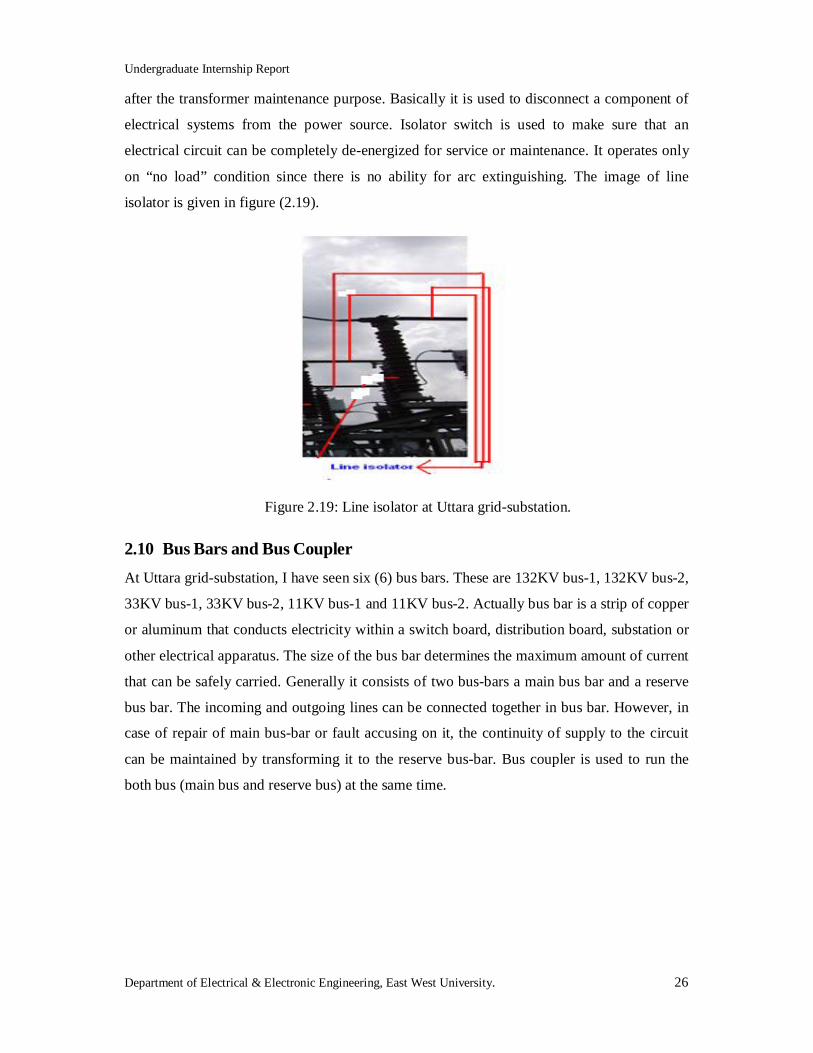
Undergraduate Internship Report
Department of Electrical & Electronic Engineering, East West University. 26
after the transformer maintenance purpose. Basically it is used to disconnect a component of
electrical systems from the power source. Isolator switch is used to make sure that an
electrical circuit can be completely de-energized for service or maintenance. It operates only
on “no load” condition since there is no ability for arc extinguishing. The image of line
isolator is given in figure (2.19).
Figure 2.19: Line isolator at Uttara grid-substation.
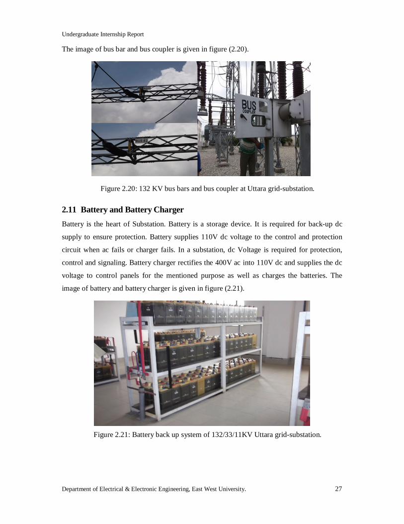
2.10 Bus Bars and Bus Coupler At Uttara grid-substation, I have seen six (6) bus bars. These are 132KV bus-1, 132KV bus-2,
33KV bus-1, 33KV bus-2, 11KV bus-1 and 11KV bus-2. Actually bus bar is a strip of copper
or aluminum that conducts electricity within a switch board, distribution board, substation or
other electrical apparatus. The size of the bus bar determines the maximum amount of current
that can be safely carried. Generally it consists of two bus-bars a main bus bar and a reserve
bus bar. The incoming and outgoing lines can be connected together in bus bar. However, in
case of repair of main bus-bar or fault accusing on it, the continuity of supply to the circuit
can be maintained by transforming it to the reserve bus-bar. Bus coupler is used to run the
both bus (main bus and reserve bus) at the same time.
Undergraduate Internship Report
Department of Electrical & Electronic Engineering, East West University. 27
The image of bus bar and bus coupler is given in figure (2.20).
Figure 2.20: 132 KV bus bars and bus coupler at Uttara grid-substation.
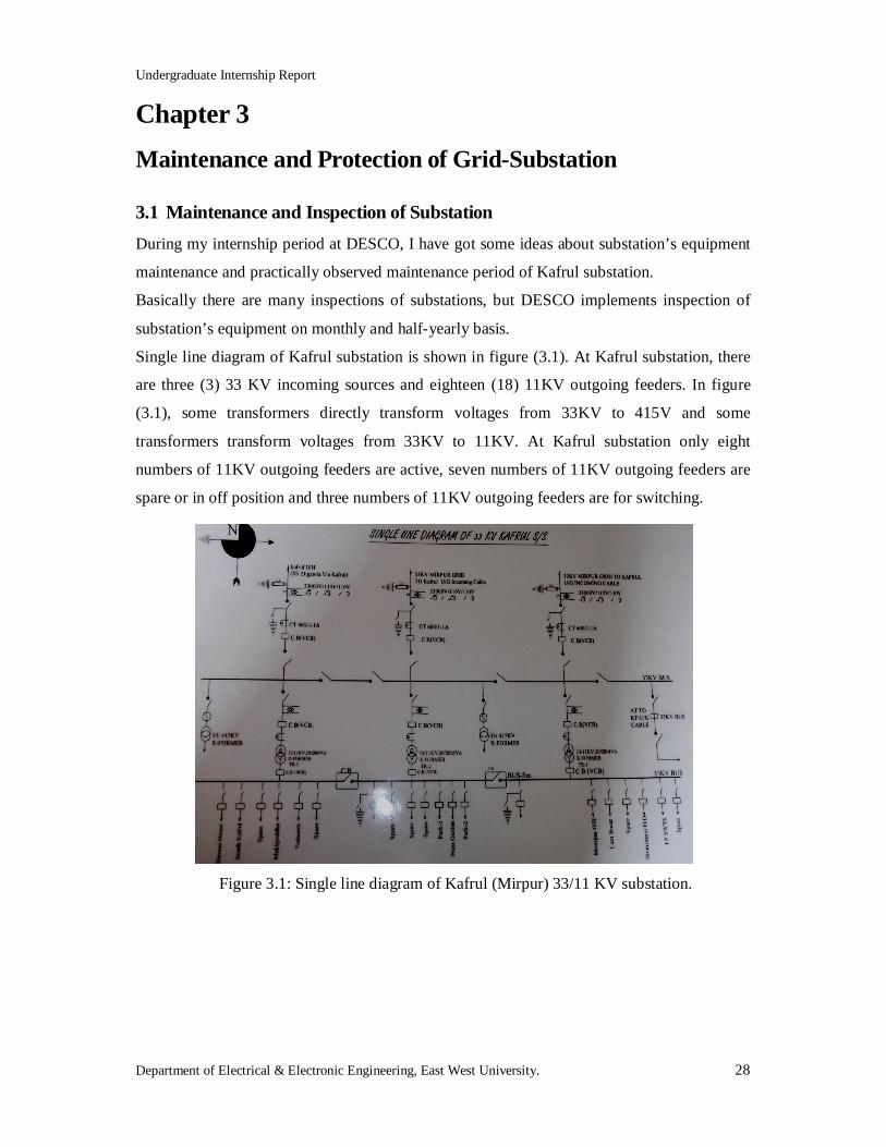
2.11 Battery and Battery Charger Battery is the heart of Substation. Battery is a storage device. It is required for back-up dc
supply to ensure protection. Battery supplies 110V dc voltage to the control and protection
circuit when ac fails or charger fails. In a substation, dc Voltage is required for protection,
control and signaling. Battery charger rectifies the 400V ac into 110V dc and supplies the dc
voltage to control panels for the mentioned purpose as well as charges the batteries. The
image of battery and battery charger is given in figure (2.21).
Figure 2.21: Battery back up system of 132/33/11KV Uttara grid-substation.
Undergraduate Internship Report
Department of Electrical & Electronic Engineering, East West University. 28
Chapter 3 Maintenance and Protection of Grid-Substation
3.1 Maintenance and Inspection of Substation During my internship period at DESCO, I have got some ideas about substation’s equipment
maintenance and practically observed maintenance period of Kafrul substation.
Basically there are many inspections of substations, but DESCO implements inspection of
substation’s equipment on monthly and half-yearly basis.
Single line diagram of Kafrul substation is shown in figure (3.1). At Kafrul substation, there
are three (3) 33 KV incoming sources and eighteen (18) 11KV outgoing feeders. In figure
(3.1), some transformers directly transform voltages from 33KV to 415V and some
transformers transform voltages from 33KV to 11KV. At Kafrul substation only eight
numbers of 11KV outgoing feeders are active, seven numbers of 11KV outgoing feeders are
spare or in off position and three numbers of 11KV outgoing feeders are for switching.
Figure 3.1: Single line diagram of Kafrul (Mirpur) 33/11 KV substation.
Undergraduate Internship Report
Department of Electrical & Electronic Engineering, East West University. 29
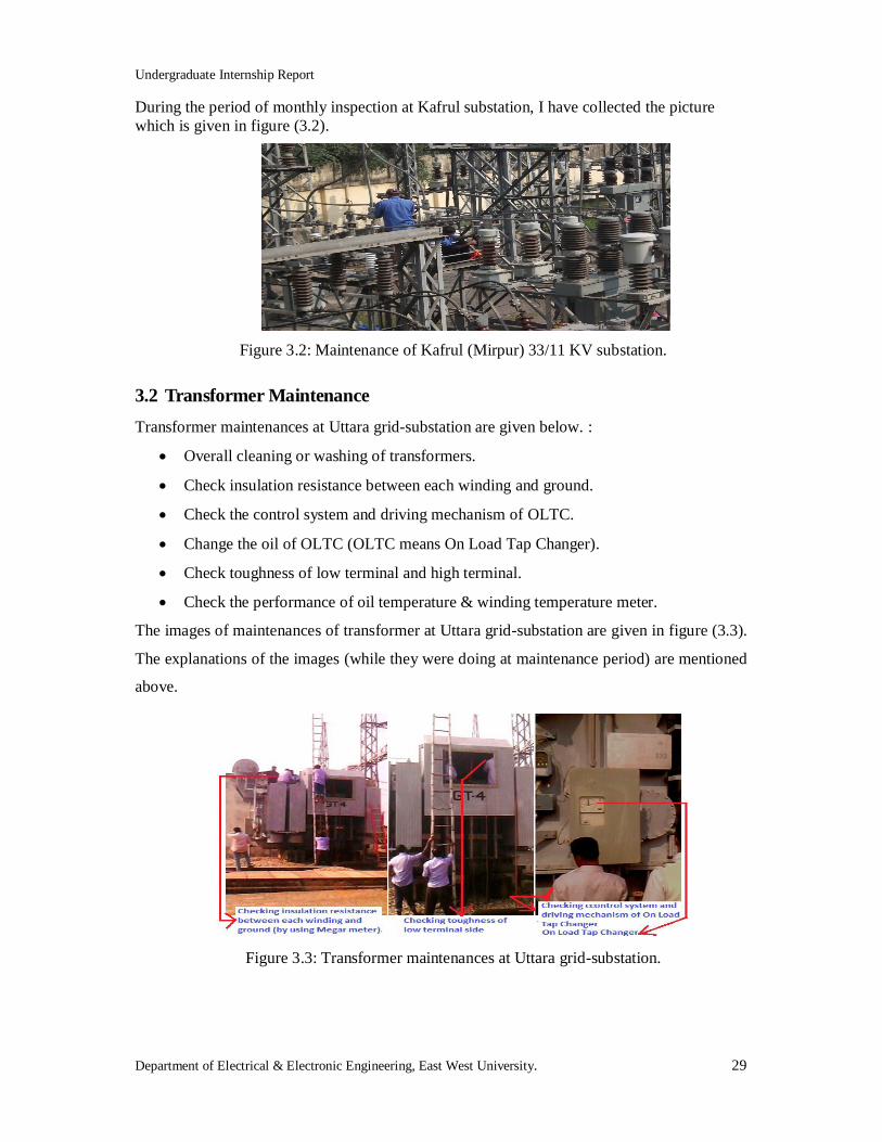
During the period of monthly inspection at Kafrul substation, I have collected the picture which is given in figure (3.2).
Figure 3.2: Maintenance of Kafrul (Mirpur) 33/11 KV substation.
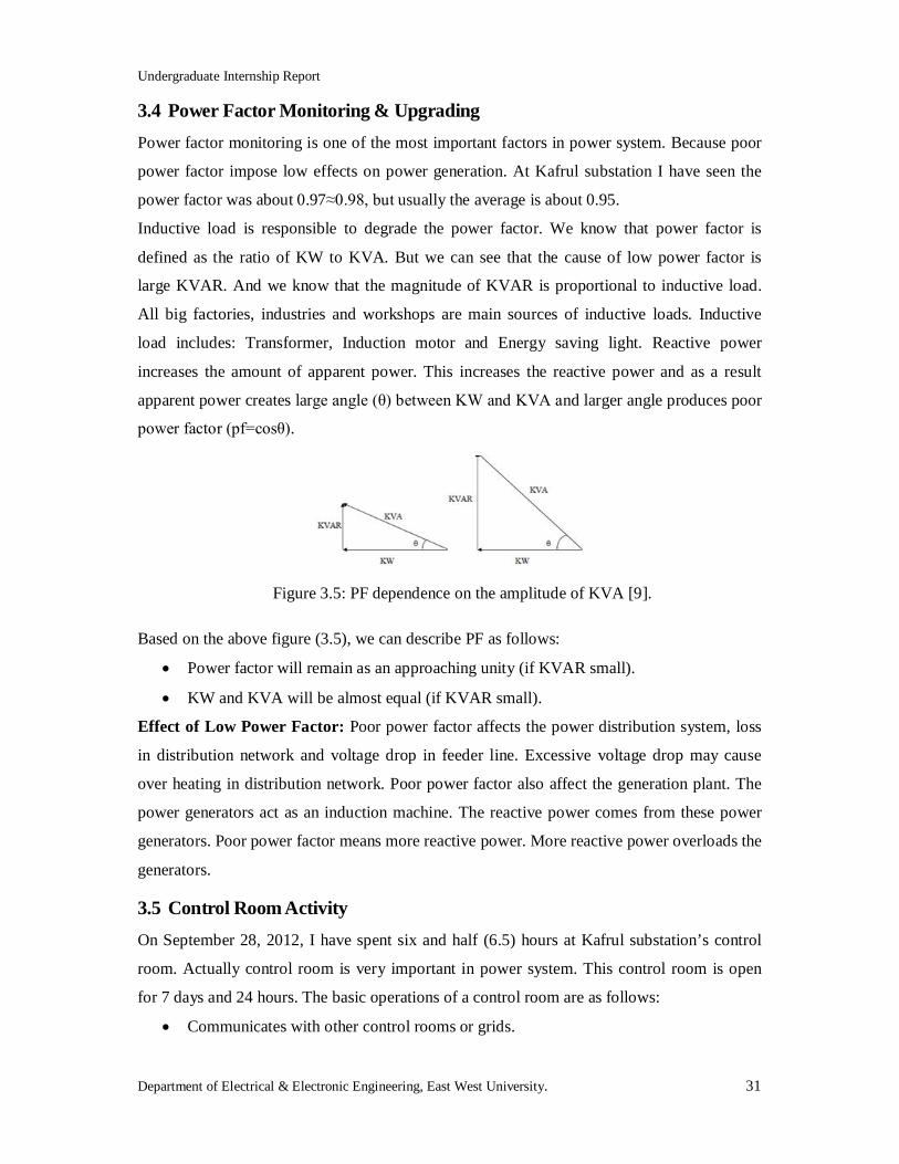
3.2 Transformer Maintenance Transformer maintenances at Uttara grid-substation are given below. :
Overall cleaning or washing of transformers.
Check insulation resistance between each winding and ground.
Check the control system and driving mechanism of OLTC.
Change the oil of OLTC (OLTC means On Load Tap Changer).
Check toughness of low terminal and high terminal.
Check the performance of oil temperature & winding temperature meter.
The images of maintenances of transformer at Uttara grid-substation are given in figure (3.3).
The explanations of the images (while they were doing at maintenance period) are mentioned
above.
Figure 3.3: Transformer maintenances at Uttara grid-substation.

Undergraduate Internship Report
Department of Electrical & Electronic Engineering, East West University. 30
3.3 Transformer Fault Detection and Repairing On September 25, 2012, I have visited the transformer repairing section at Kafrul substation
with Md.Momraj Khan, Jr. Assistant Manager (Kafrul Sales & Distribution division). He
explained me about the common faults of transformer which are given below:
Transformer coil burn.
Drop off fuse.
Low dielectric strength in transformer oil.
Transformer Coil Burn: Coil burn process happens when distribution transformer runs
under overload for long days. For detecting transformer fault, at first the ‘insulation tester’ is
used. This insulation tester measures the resistance of transformer insulation. This tester has a
prime mover, mega Ω meter and two probes. To test the transformer insulation, one probe is
connected to high side and another one to low side. Then the prime mover is rotating by 120
rpm (rotating per minute) and produces very low current follow like 100V. If the meter shows
the resistive value less than 5 MΩ, it means coil is burned, otherwise the tester shows more or
equal to 30 MΩ. The image of distribution transformer is given in figure (3.4).
Figure 3.4: The 11/.415KV distribution transformer [10].
Drop off Fuse: Drop off fuse is a protection to protect transformer from burning. It is used,
when transformer’s distribution or feeder lines falls in short circuit or ground fault.
Low Dielectric Strength: One kind of oil is used in transformer to isolate the coil-container
and to keep cool the transformer. This oil is a dielectric material. If the oil dielectric value
decreases, the core can be burned or a serious accident could be occurred. So, DESCO
usually checks the oil dielectric strength in every two or three years ever since the
transformer is installed.
Undergraduate Internship Report
Department of Electrical & Electronic Engineering, East West University. 31
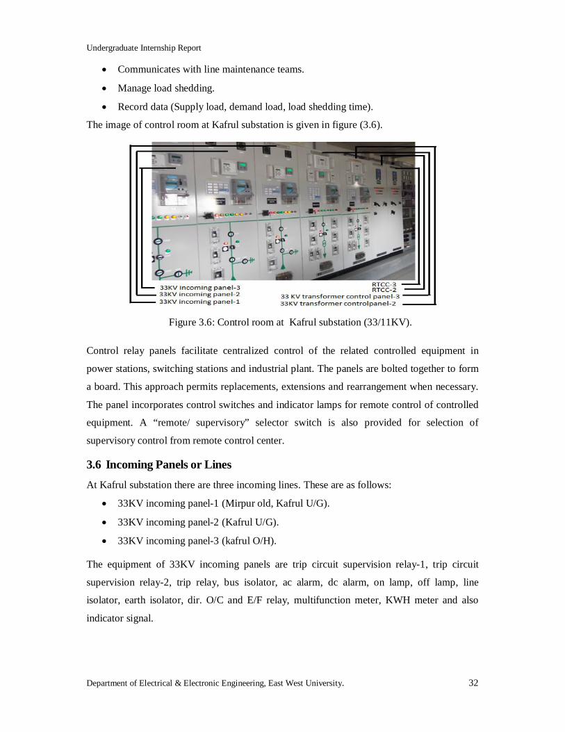
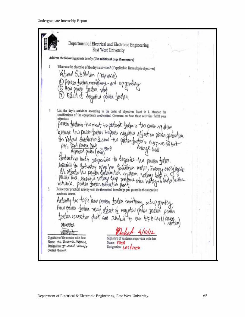
3.4 Power Factor Monitoring & Upgrading Power factor monitoring is one of the most important factors in power system. Because poor
power factor impose low effects on power generation. At Kafrul substation I have seen the
power factor was about 0.97≈0.98, but usually the average is about 0.95.
Inductive load is responsible to degrade the power factor. We know that power factor is
defined as the ratio of KW to KVA. But we can see that the cause of low power factor is
large KVAR. And we know that the magnitude of KVAR is proportional to inductive load.
All big factories, industries and workshops are main sources of inductive loads. Inductive
load includes: Transformer, Induction motor and Energy saving light. Reactive power
increases the amount of apparent power. This increases the reactive power and as a result
apparent power creates large angle (θ) between KW and KVA and larger angle produces poor
power factor (pf=cosθ).
Figure 3.5: PF dependence on the amplitude of KVA [9].
Based on the above figure (3.5), we can describe PF as follows:
Power factor will remain as an approaching unity (if KVAR small).
KW and KVA will be almost equal (if KVAR small).
Effect of Low Power Factor: Poor power factor affects the power distribution system, loss
in distribution network and voltage drop in feeder line. Excessive voltage drop may cause
over heating in distribution network. Poor power factor also affect the generation plant. The
power generators act as an induction machine. The reactive power comes from these power
generators. Poor power factor means more reactive power. More reactive power overloads the
generators.
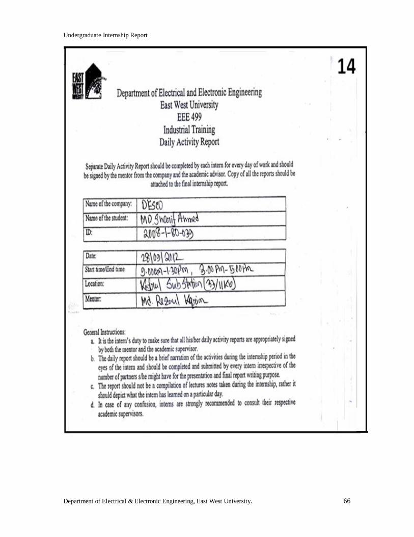
3.5 Control Room Activity On September 28, 2012, I have spent six and half (6.5) hours at Kafrul substation’s control
room. Actually control room is very important in power system. This control room is open
for 7 days and 24 hours. The basic operations of a control room are as follows:
Communicates with other control rooms or grids.
Undergraduate Internship Report
Department of Electrical & Electronic Engineering, East West University. 32
Communicates with line maintenance teams.
Manage load shedding.
Record data (Supply load, demand load, load shedding time).
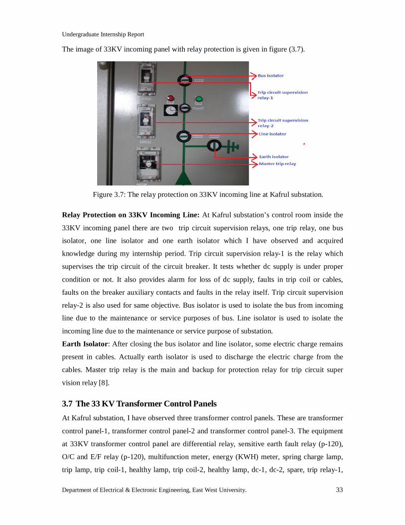
The image of control room at Kafrul substation is given in figure (3.6).
Figure 3.6: Control room at Kafrul substation (33/11KV).
Control relay panels facilitate centralized control of the related controlled equipment in
power stations, switching stations and industrial plant. The panels are bolted together to form
a board. This approach permits replacements, extensions and rearrangement when necessary.
The panel incorporates control switches and indicator lamps for remote control of controlled
equipment. A “remote/ supervisory” selector switch is also provided for selection of
supervisory control from remote control center.
3.6 Incoming Panels or Lines At Kafrul substation there are three incoming lines. These are as follows:
33KV incoming panel-1 (Mirpur old, Kafrul U/G).
33KV incoming panel-2 (Kafrul U/G).
33KV incoming panel-3 (kafrul O/H).
The equipment of 33KV incoming panels are trip circuit supervision relay-1, trip circuit
supervision relay-2, trip relay, bus isolator, ac alarm, dc alarm, on lamp, off lamp, line
isolator, earth isolator, dir. O/C and E/F relay, multifunction meter, KWH meter and also
indicator signal.
Undergraduate Internship Report
Department of Electrical & Electronic Engineering, East West University. 33
The image of 33KV incoming panel with relay protection is given in figure (3.7).
Figure 3.7: The relay protection on 33KV incoming line at Kafrul substation.
Relay Protection on 33KV Incoming Line: At Kafrul substation’s control room inside the
33KV incoming panel there are two trip circuit supervision relays, one trip relay, one bus
isolator, one line isolator and one earth isolator which I have observed and acquired
knowledge during my internship period. Trip circuit supervision relay-1 is the relay which
supervises the trip circuit of the circuit breaker. It tests whether dc supply is under proper
condition or not. It also provides alarm for loss of dc supply, faults in trip coil or cables,
faults on the breaker auxiliary contacts and faults in the relay itself. Trip circuit supervision
relay-2 is also used for same objective. Bus isolator is used to isolate the bus from incoming
line due to the maintenance or service purposes of bus. Line isolator is used to isolate the
incoming line due to the maintenance or service purpose of substation.
Earth Isolator: After closing the bus isolator and line isolator, some electric charge remains
present in cables. Actually earth isolator is used to discharge the electric charge from the
cables. Master trip relay is the main and backup for protection relay for trip circuit super
vision relay [8].
3.7 The 33 KV Transformer Control Panels At Kafrul substation, I have observed three transformer control panels. These are transformer
control panel-1, transformer control panel-2 and transformer control panel-3. The equipment
at 33KV transformer control panel are differential relay, sensitive earth fault relay (p-120),
O/C and E/F relay (p-120), multifunction meter, energy (KWH) meter, spring charge lamp,
trip lamp, trip coil-1, healthy lamp, trip coil-2, healthy lamp, dc-1, dc-2, spare, trip relay-1,
Undergraduate Internship Report
Department of Electrical & Electronic Engineering, East West University. 34
trip relay-2, trip circuit supervision relay-1, trip circuit supervision relay-2, auxiliary relay-1
(BZ main tank and PRD main tank), auxiliary relay-2 (WTT and OLT), auxiliary relay-3 (BZ
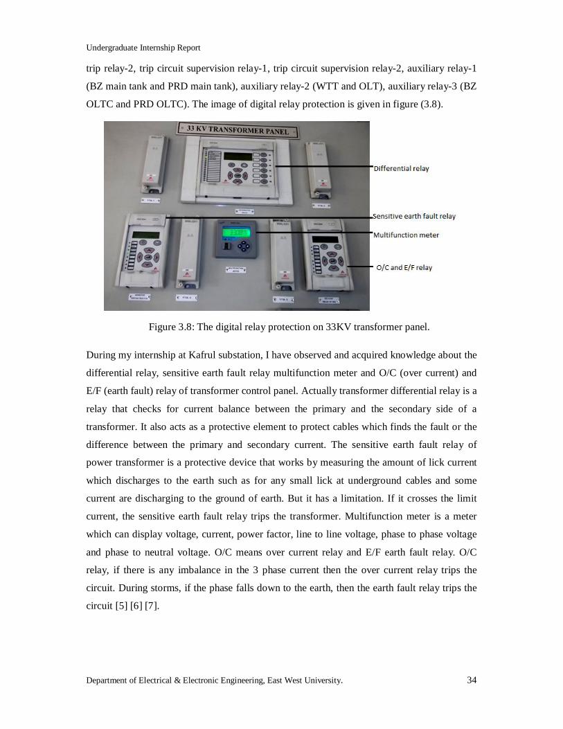
OLTC and PRD OLTC). The image of digital relay protection is given in figure (3.8).
Figure 3.8: The digital relay protection on 33KV transformer panel.
During my internship at Kafrul substation, I have observed and acquired knowledge about the
differential relay, sensitive earth fault relay multifunction meter and O/C (over current) and
E/F (earth fault) relay of transformer control panel. Actually transformer differential relay is a
relay that checks for current balance between the primary and the secondary side of a
transformer. It also acts as a protective element to protect cables which finds the fault or the
difference between the primary and secondary current. The sensitive earth fault relay of
power transformer is a protective device that works by measuring the amount of lick current
which discharges to the earth such as for any small lick at underground cables and some
current are discharging to the ground of earth. But it has a limitation. If it crosses the limit
current, the sensitive earth fault relay trips the transformer. Multifunction meter is a meter
which can display voltage, current, power factor, line to line voltage, phase to phase voltage
and phase to neutral voltage. O/C means over current relay and E/F earth fault relay. O/C
relay, if there is any imbalance in the 3 phase current then the over current relay trips the
circuit. During storms, if the phase falls down to the earth, then the earth fault relay trips the
circuit [5] [6] [7].
Undergraduate Internship Report
Department of Electrical & Electronic Engineering, East West University. 35
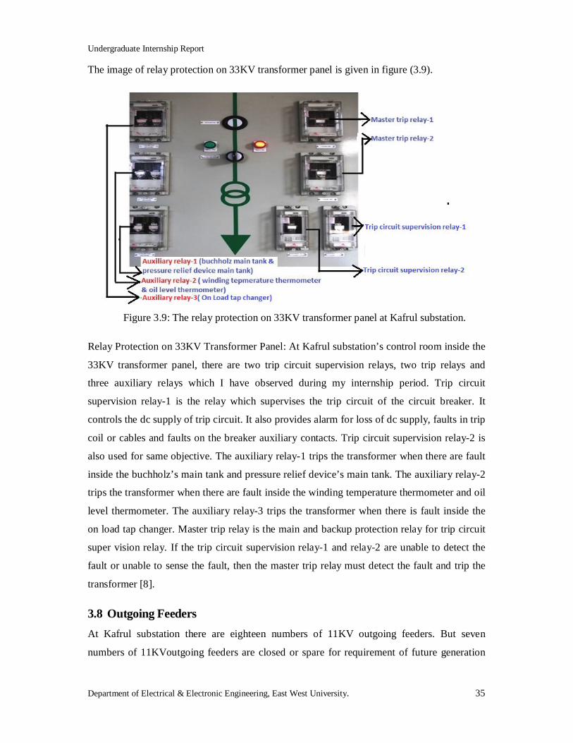
The image of relay protection on 33KV transformer panel is given in figure (3.9).
Figure 3.9: The relay protection on 33KV transformer panel at Kafrul substation.
Relay Protection on 33KV Transformer Panel: At Kafrul substation’s control room inside the
33KV transformer panel, there are two trip circuit supervision relays, two trip relays and
three auxiliary relays which I have observed during my internship period. Trip circuit
supervision relay-1 is the relay which supervises the trip circuit of the circuit breaker. It
controls the dc supply of trip circuit. It also provides alarm for loss of dc supply, faults in trip
coil or cables and faults on the breaker auxiliary contacts. Trip circuit supervision relay-2 is
also used for same objective. The auxiliary relay-1 trips the transformer when there are fault
inside the buchholz’s main tank and pressure relief device’s main tank. The auxiliary relay-2
trips the transformer when there are fault inside the winding temperature thermometer and oil
level thermometer. The auxiliary relay-3 trips the transformer when there is fault inside the
on load tap changer. Master trip relay is the main and backup protection relay for trip circuit
super vision relay. If the trip circuit supervision relay-1 and relay-2 are unable to detect the
fault or unable to sense the fault, then the master trip relay must detect the fault and trip the
transformer [8].
3.8 Outgoing Feeders At Kafrul substation there are eighteen numbers of 11KV outgoing feeders. But seven
numbers of 11KVoutgoing feeders are closed or spare for requirement of future generation
Undergraduate Internship Report
Department of Electrical & Electronic Engineering, East West University. 36
and three numbers of 11KV outgoing feeders are for switching and only eight numbers of
11KV outgoing feeders are active for the distribution of electricity.
Undergraduate Internship Report
Department of Electrical & Electronic Engineering, East West University. 37
Chapter 4 Conclusion
4.1 Discussion I have spent some remarkable days at DESCO during my internship program. DESCO is one
of the best practical grounds for the Electrical and Electronic Engineers in our country. I must
say the theories that I have learned at my University was practically observed by me at
DESCO. I consider myself very much lucky to have my internship program with a reputed
electricity distribution company like DESCO. It gave me an opportunity to implement my
theoretical knowledge in practically. My achievements from DESCO are as follows:
Industrial training provided by DESCO has enriched my practical knowledge.
It has enlarged my thinking capacity about practical operations of the different
equipment.
It has increased my confidence level for facing job interview in future.
DESCO gave me a unique experience of observing the equipment of substation.
The friendly environment in DESCO encouraged me to co-operate with each other. I have
learned a lot and obtained practical knowledge during my internship at DESCO which will
help me in future life.
4.2 Problems I have already gathered some knowledge about DESCO’s practical operations. But within the
limited time it was really difficult task to gather the whole knowledge about everything. Due
to some privacy problem I could not get enough pictures and enough accesses to every place.
Due to some mechanical fault, it was really a difficult task to visit and gather some
knowledge about Kafrul substation. Moreover, I could not get the opportunity to learn about
the new project of DESCO because the project manager of DESCO was outside the country.
At that time due to the frequent maintenance at Uttara grid; it was not possible for me to
know about the coolers of the grid. Due to some technical problems I could not observe the
single bus bar of Mirpur substation.
4.3 Recommendation During my internship period I had been introduced to some mechanical instruments. But at
our University there is no mechanical engineering course according to our course curriculum.
Undergraduate Internship Report
Department of Electrical & Electronic Engineering, East West University. 38
That is why I had faced some problems during observation of these instruments. So, I just
want to make a request to our academic faculty members and our authority to consider for
adding a mechanical engineering course in our course curriculum. I hope this surely will help
the upcoming students to understand about the mechanical instruments and their uses.
Moreover students need to learn more power related theoretical knowledge before going for
their internship program.
Undergraduate Internship Report
Department of Electrical & Electronic Engineering, East West University. 39
References
[1] History of Dhaka Electric Supply Company,
[Online]. Available: http://www.desco.org.bd/
[2] Transformer and its working Principle, [Online]. Available:
http://www.electrical4u.com/electrical-transformer/working-principle-transformer.php.
[3] Wiki answer, the primary winding and the secondary winding of a transformer, [Online].
Available: http://wiki.answer.com/Q/what is the primary winding and the secondary
winding of a transformer.
[4] Wiki answer, Function of a buchholz relay, [Online]. Available:
http://wiki.answer.com/Q/what is a buchholz relay.
[5] Differential protection of transformer (differential relays), [Online].Available:
http://www.electrical4u.com/differential-protection-of-transformer-differential-relays/.
[6] Directional sensitive earth fault, the electrical engineering section, [Online]. Available:
http://www.cr4.globalspec.com/thread/77378/Directional-sensitive-Earth-Fault.
[7] Wise geek clear answer, Function of an over current relay, [Online]. Available:
http://www.wisegeek.com/what-is-an-overcurrent-relay.htm.
[8] Function of a trip circuit supervision relay and its working principal, [Online].
Available: http://www.allinterview.com/showanswers/132221.html.
[9] Photo taken by author from personal communication at DESCO.
[10] Photo taken by author from Local Street at Gulsan-1.
Undergraduate Internship Report
Department of Electrical & Electronic Engineering, East West University. 40
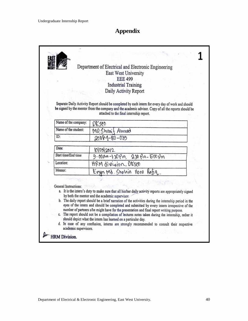
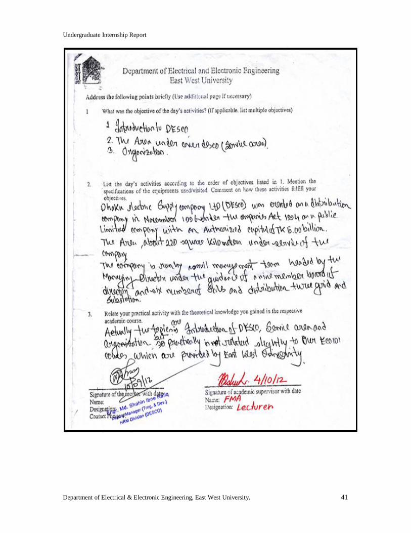
Appendix
Undergraduate Internship Report
Department of Electrical & Electronic Engineering, East West University. 41
Undergraduate Internship Report
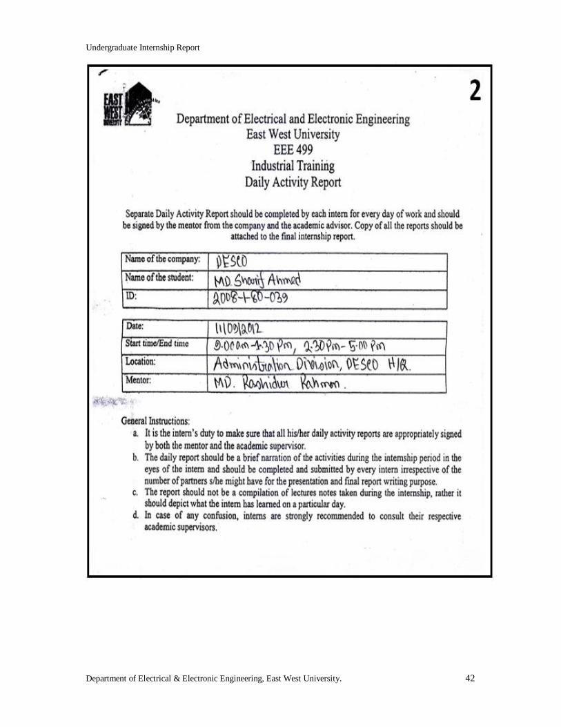
Department of Electrical & Electronic Engineering, East West University. 42
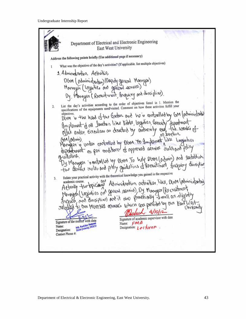
Undergraduate Internship Report
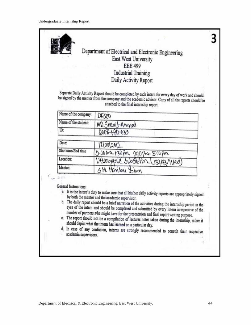
Department of Electrical & Electronic Engineering, East West University. 43
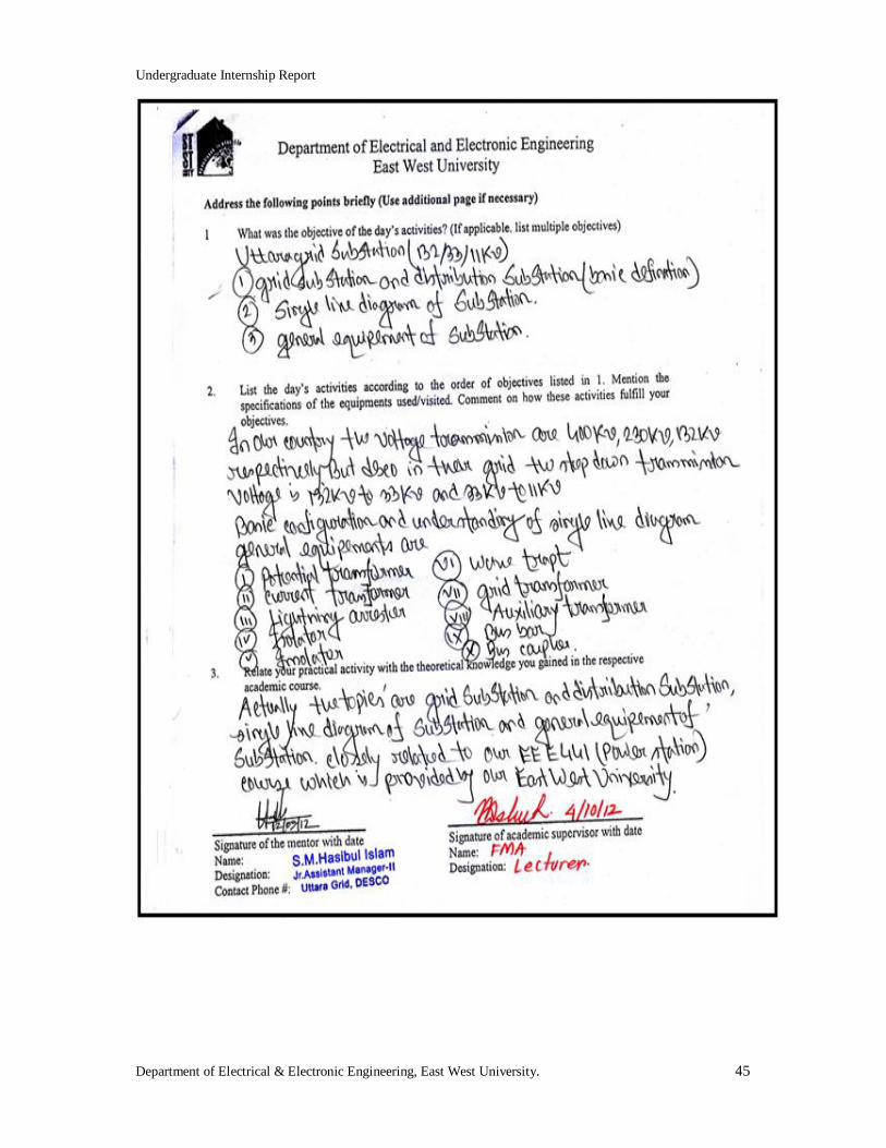
Undergraduate Internship Report
Department of Electrical & Electronic Engineering, East West University. 44
Undergraduate Internship Report
Department of Electrical & Electronic Engineering, East West University. 45
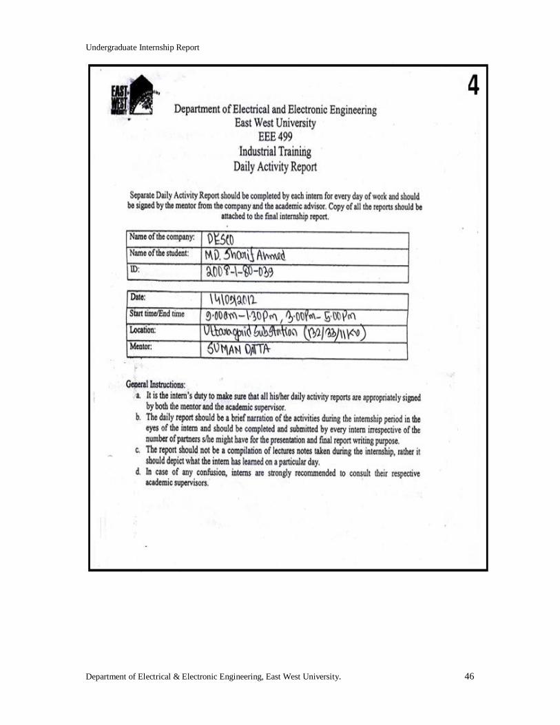
Undergraduate Internship Report
Department of Electrical & Electronic Engineering, East West University. 46

Undergraduate Internship Report
Department of Electrical & Electronic Engineering, East West University. 47
Undergraduate Internship Report
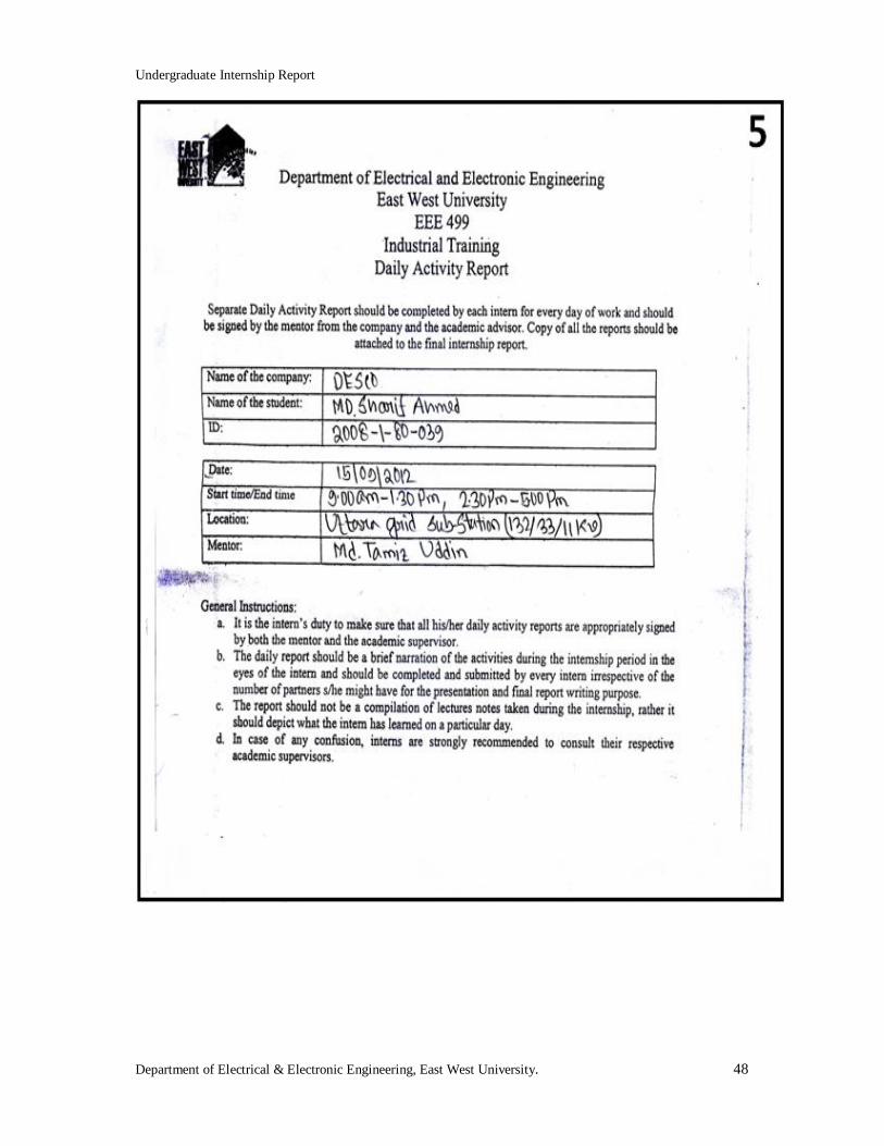
Department of Electrical & Electronic Engineering, East West University. 48
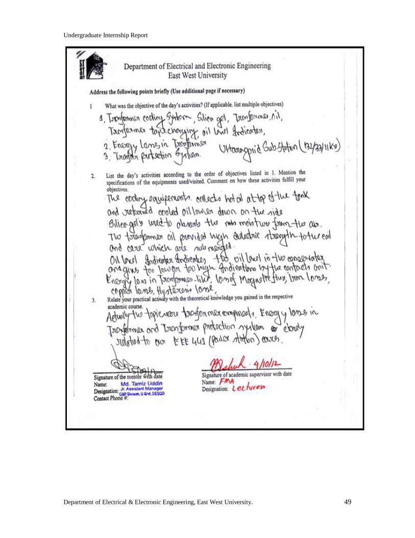
Undergraduate Internship Report
Department of Electrical & Electronic Engineering, East West University. 49
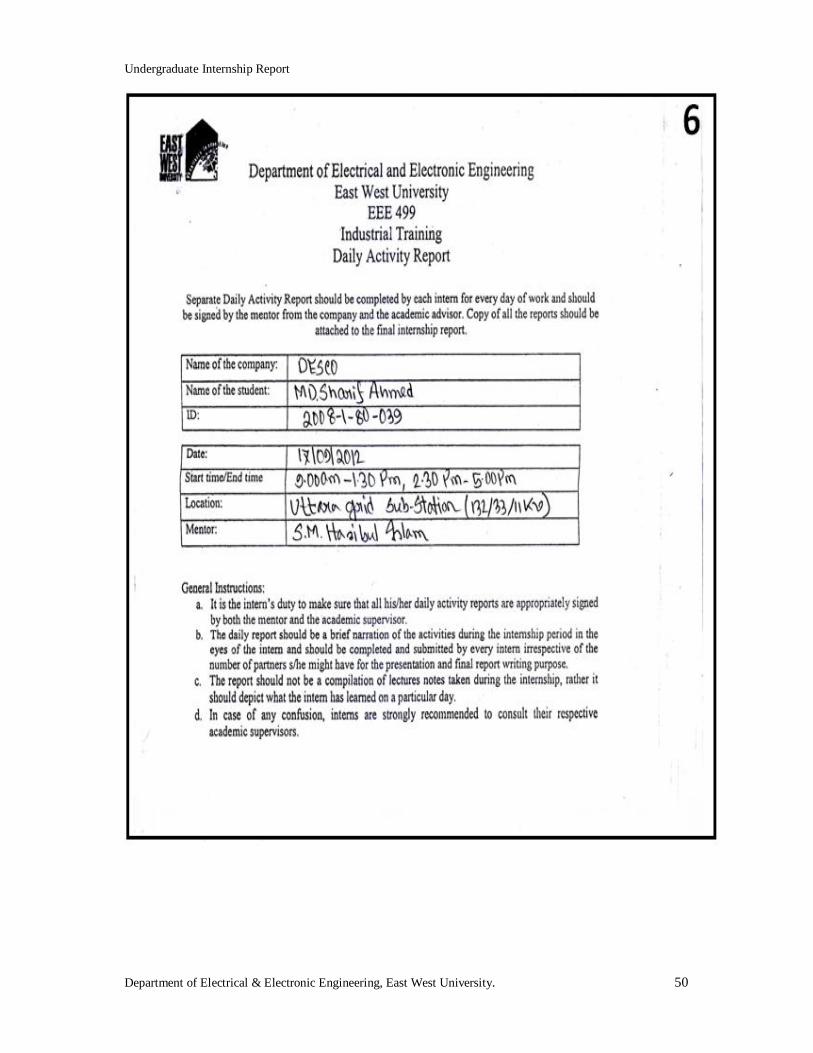
Undergraduate Internship Report
Department of Electrical & Electronic Engineering, East West University. 50
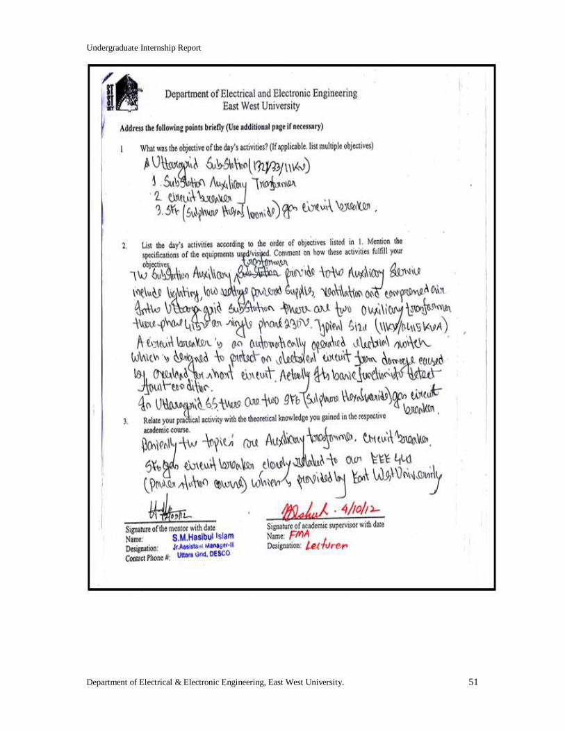
Undergraduate Internship Report
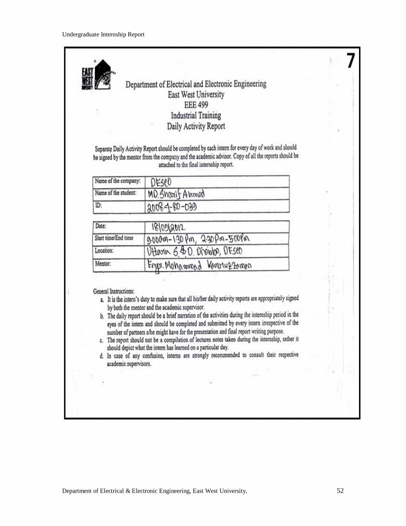
Department of Electrical & Electronic Engineering, East West University. 51
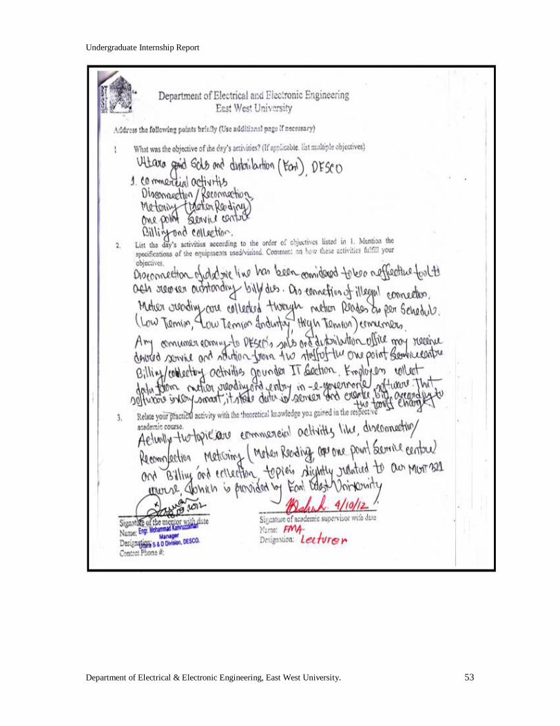
Undergraduate Internship Report
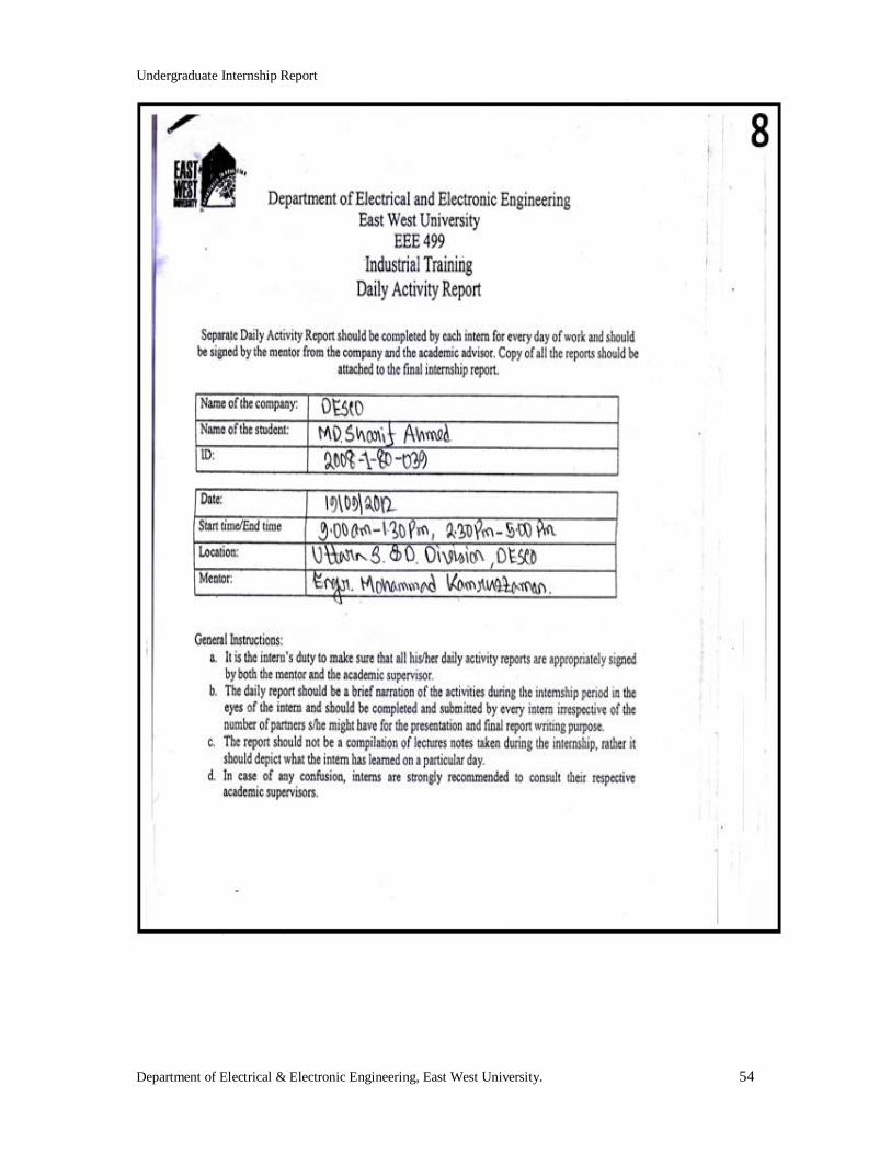
Department of Electrical & Electronic Engineering, East West University. 52
Undergraduate Internship Report
Department of Electrical & Electronic Engineering, East West University. 53
Undergraduate Internship Report
Department of Electrical & Electronic Engineering, East West University. 54
Undergraduate Internship Report
Department of Electrical & Electronic Engineering, East West University. 55
Undergraduate Internship Report
Department of Electrical & Electronic Engineering, East West University. 56
Undergraduate Internship Report
Department of Electrical & Electronic Engineering, East West University. 57
Undergraduate Internship Report
Department of Electrical & Electronic Engineering, East West University. 58
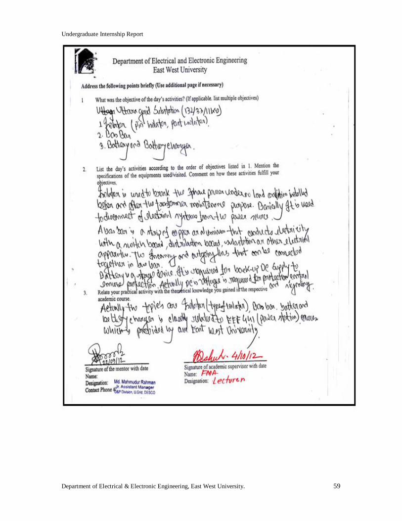
Undergraduate Internship Report
Department of Electrical & Electronic Engineering, East West University. 59
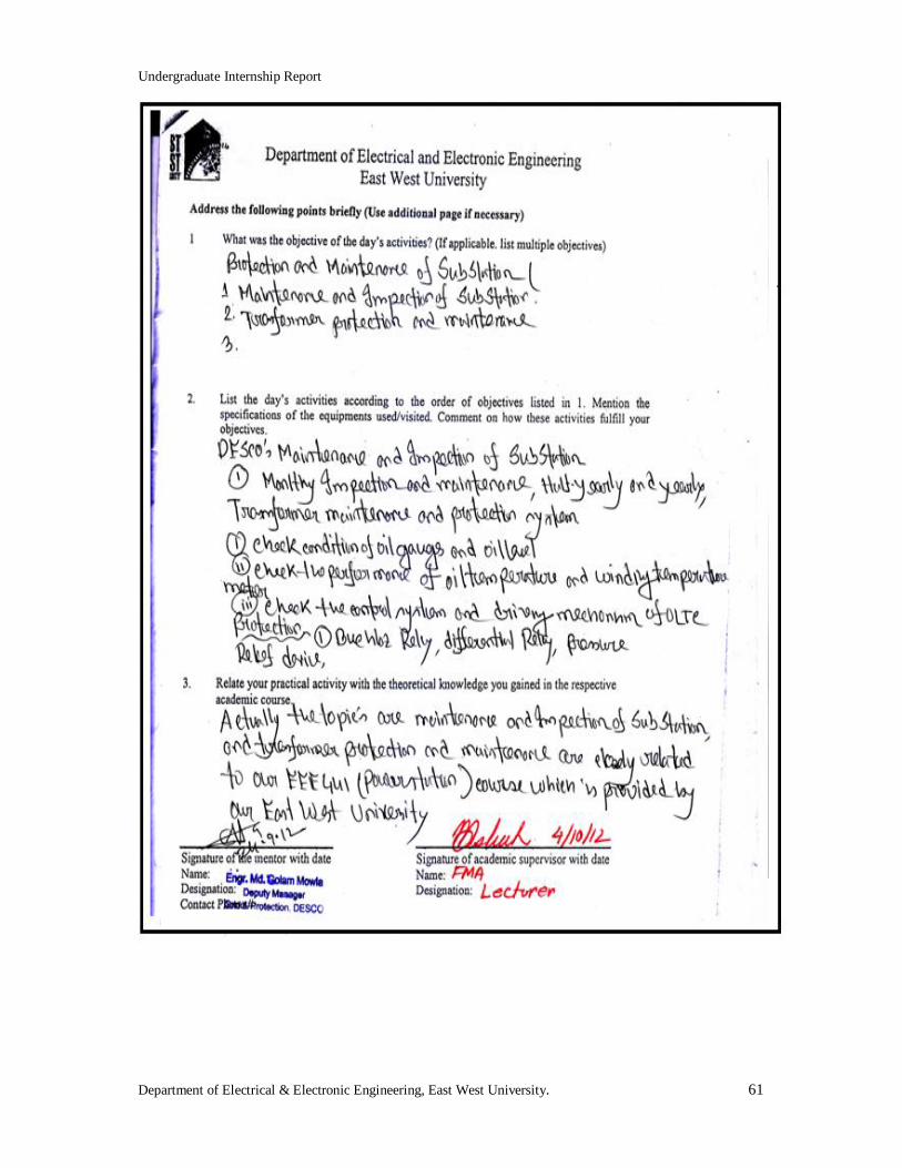
Undergraduate Internship Report
Department of Electrical & Electronic Engineering, East West University. 60
Undergraduate Internship Report
Department of Electrical & Electronic Engineering, East West University. 61

Undergraduate Internship Report
Department of Electrical & Electronic Engineering, East West University. 62

Undergraduate Internship Report
Department of Electrical & Electronic Engineering, East West University. 63
Undergraduate Internship Report
Department of Electrical & Electronic Engineering, East West University. 64
Undergraduate Internship Report
Department of Electrical & Electronic Engineering, East West University. 65
Undergraduate Internship Report
Department of Electrical & Electronic Engineering, East West University. 66

Undergraduate Internship Report
Department of Electrical & Electronic Engineering, East West University. 67
Undergraduate Internship Report
Department of Electrical & Electronic Engineering, East West University. 68
Undergraduate Internship Report
Department of Electrical & Electronic Engineering, East West University. 69