Eaching High-rise Plumbing Design
19
A C 2011-2739 : TEA CHING HIGH- RISE PLUMBING DESIGN FOR EN- GINEERS Ahmed Cherif Megri, University of Wyoming Dr. Ahmed Cherif Megri, associate professor of architectural engineering at the University of Wyoming (UW), teach es sever al HV AC and energy course s. Dr . Meg ri is also teachi ng a cours e titled ”Compre- hensive Performance of Building Env elope and HV AC Systems” for Summer School at UW , and ”Smoke and Fire Dynamics” during summer session at Concordia University, Canada. His research areas include airflow modeling, zonal modeling, energy modeling, and artificial intelligence modeling using the support vector machine learning approach. Prior to his actual position at UW , he was an assistant professor and the director of Architectural Engineering Program at Illinois Institute of Technology (IIT). He was re- sponsible for developing the current architectural engineering undergraduate and master’s programs at the Illinois Institute of Technology (IIT). During his stay at IIT, he taught fundamental engineering courses, such as thermodynamics and heat transfer, as well as design courses, such as HVAC, energy, plumbing, fire protect ion and lighti ng. Also, he supervis e man y cours es in the frame of inter profe ssion al projects program (I PRO). In few months, Dr. Megri will defend his ”Habilitation” (HDR) degree at Pierre and Marie Curie Univer- sity - Paris VI, Sorbonne Universities. c American Society for Engineering Education, 2011
-
Upload
msalah20202000 -
Category
Documents
-
view
228 -
download
0
Transcript of Eaching High-rise Plumbing Design

7/27/2019 Eaching High-rise Plumbing Design
http://slidepdf.com/reader/full/eaching-high-rise-plumbing-design 1/19
AC 2011-2739: TEACHING HIGH-RISE PLUMBING DESIGN FOR EN-GINEERS
Ahmed Cherif Megri, University of Wyoming
Dr. Ahmed Cherif Megri, associate professor of architectural engineering at the University of Wyoming
(UW), teaches several HVAC and energy courses. Dr. Megri is also teaching a course titled ”Compre-
hensive Performance of Building Envelope and HVAC Systems” for Summer School at UW, and ”Smoke
and Fire Dynamics” during summer session at Concordia University, Canada. His research areas include
airflow modeling, zonal modeling, energy modeling, and artificial intelligence modeling using the support
vector machine learning approach. Prior to his actual position at UW, he was an assistant professor and
the director of Architectural Engineering Program at Illinois Institute of Technology (IIT). He was re-
sponsible for developing the current architectural engineering undergraduate and master’s programs at the
Illinois Institute of Technology (IIT). During his stay at IIT, he taught fundamental engineering courses,
such as thermodynamics and heat transfer, as well as design courses, such as HVAC, energy, plumbing,
fire protection and lighting. Also, he supervise many courses in the frame of interprofessional projects
program (IPRO).
In few months, Dr. Megri will defend his ”Habilitation” (HDR) degree at Pierre and Marie Curie Univer-
sity - Paris VI, Sorbonne Universities.
cAmerican Society for Engineering Education, 2011

7/27/2019 Eaching High-rise Plumbing Design
http://slidepdf.com/reader/full/eaching-high-rise-plumbing-design 2/19
2011 ASEE Annual Conference
Teaching High-rise Plumbing Design for Engineers
Ahmed Cherif Megri
Associate Professor, [email protected]
University of Wyoming
Civil and Architectural Engineering DepartmentLaramie, WY, USA
The architectural engineering program at the University of Wyoming offers several courses in the areas
of HVAC, Plumbing, Fire Protection, Energy and Building Electricity.
Plumbing is a discipline founded in hydraulics and legal issues governed by codes and standards. This
discipline includes, but is not limited to, the design of hot and cold water, storm, drainage and venting
systems. Many documents, books and references are available covering the topics associated with
plumbing. However, the majority of them are oriented toward plumbing techniques and practical
issues.
Within this paper we discuss the integration of plumbing into the Architectural Engineering curriculum,
as well as how high-rise plumbing can be taught for engineers. We also discuss how to combine the
fundamentals, such as hydraulics, and different codes and standards, to create a successful class. A
comprehensive capstone project that will integrate various components of plumbing will be discussed in
this paper. The particularity of high-rise plumbing vs. low-rise plumbing is also discussed.
Also, this paper describes the experiences we encountered over the past several years while
developing and teaching the plumbing curricula in the Architectural Engineering program. In
addition, we describe the history of the architectural engineering curriculum at the University of
Wyoming, the plumbing design project, and the building design process.
Most importantly, project methodology will be discussed, including the design of various systems,system selection and commissioning, and will culminate with administrative topics. We demonstrate
this methodology through the use of a comprehensive design project.
We discuss this design course from the students’ point of view, focusing on the experience gained in
design, codes and safety, as well as in written and oral communication skills. We also describe the
methods we use in terms of learning outcomes to evaluate the effectiveness of the capstone design
program.
Introduction:
Plumbing is a growing area. One decade ago, the plumbing projects focus on hot/cold water,
drainage/venting and storm systems. These days, many new subjects have been introduced, such as
rainwater harvesting, water reclamation, graywater, green plumbing and so on.
High-rise building, also called high-rise, multistory building tall enough to require the use of a system of
mechanical vertical transportation such as elevators. The skyscraper is a very tall high-rise building.
7/27/2019 Eaching High-rise Plumbing Design
http://slidepdf.com/reader/full/eaching-high-rise-plumbing-design 3/19
2011 ASEE Annual Conference
The International Building Code (2009), section 403 defines a high-rise building as a building with an
occupied floor located more than 75 feet (22 860 mm) above the lowest level of fire department vehicle
access (the level where the firefighting apparatus would stage firefighting operations). The same
definition is given by NFPA “Fire Protection Association”. Basically, the number of story is irrelevant and
the only consideration is the height of the building. The first high-rise buildings were constructed in the
United States in the 1880s. They arose in downtown areas where increased land prices and great
population densities created a demand for buildings that rose vertically rather than spread horizontally,
thus occupying less precious land area. High-rise are usually residential, multi-purpose commercial
buildings or mixed-use buildings.
High-rise buildings are challenging to build architecturally and also they are challenging in term of
engineering design, such as pumping cold and hot water, and mechanical uses, such as cooling towers
and supplying HVAC equipment (Larson, 2007).
Vertical piping systems are generally more economic and need less maintenance than horizontal piping
systems in multilevel projects. Vertical piping uses fewer supports, hangers, and inserts and requires less
horizontal space in ceiling plenums for sloping to achieve drainage (Connelly, 2007). However, the
drawback of vertical piping is the multiple penetrations through structural slabs. Each of thesepenetrations must be sealed or protected to fulfill the requirements of building codes, in term of
protecting the building pressurization and also to prevent vertical migration of fire and smoke. The
location of these multiple penetrations is critical to the integrity of the structure and the function of the
fixtures even more than the aesthetics of the built environment. Tall buildings require more robust
structures, further limiting the allowable space for penetrations. Other structural practices, such as post-
tensioned beams and slabs, which serve to lighten the overall building structure, can limit even further
the available locations for slab penetrations (Larson, 2007).
Domestic Water systems:
High-rise plumbing usually uses vertical piping systems in terms of water distribution, drainage/venting.High-rise plumbing has several specificities in comparison to other type of buildings:
Pressure distribution:
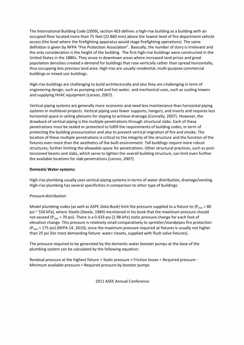
Model plumbing codes (as well as ASPE Data Book) limit the pressure supplied to a fixture to (Pmax = 80
psi ~ 550 kPa), where Steele (Steele, 1984) mentioned in his book that the maximum pressure should
not exceed (Pmax = 70 psi). There is a 0.433-psi (2.98-kPa) static pressure change for each foot of
elevation change. This pressure is relatively small comparatively to sprinkler/standpipes fire protection
(Pmax = 175 psi) (NFPA 14, 2010), since the maximum pressure required at fixtures is usually not higher
than 25 psi (for most demanding fixture: water closets, supplied with flush valve fixtures).
The pressure required to be generated by the domestic water booster pumps at the base of the
plumbing system can be calculated by the following equation:
Residual pressure at the highest fixture + Static pressure + Friction losses = Required pressure -
Minimum available pressure = Required pressure by booster pumps

7/27/2019 Eaching High-rise Plumbing Design
http://slidepdf.com/reader/full/eaching-high-rise-plumbing-design 4/19
2011 ASEE Annual Conference
The second reason to have limitation of water pressure is to limit the water velocity below critical values
(~10 fps) for noise considerations and to avoid erosion of piping, water hammer, damage to fixtures and
equipment, excessive equipment costs. The objective of a designer is to have a system where the
pressure is controlled, usually by either placing pressure reducing valves on each level where pressure
exceeds the code maximum or branching from the higher pressure riser to make a pressure zone. This
pressure zone uses a central pressure-reducing valve and sub-riser to meet the minimum pressure
required at the highest level and the maximum pressure allowed at the lowest level. This particular
method has been used successfully in many high-rise building designs (Connelly, 2007).
Other considerations for water distribution system is the building height, available municipal water
pressure, pressure requirements at different floor throughout the building and at the upper floor, flow
demand, booster pump capacity and control, pipe and valve materials, riser locations, pressure zones,
pressure-regulating stations, water heater storage capacity and recovery, water heater locations,
domestic hot water circulation or pipe temperature maintenance, space requirements in the building,
economics, energy efficiency, and acoustics.
Zoning:
To avoid excessive pressure, several schemes have been developed over years to achieve an
economical, efficient and conserving installation. Usually building over 100 feet in height require
multiple water distribution zones.
Cold water Distribution:
High-rise buildings use several pumping schemes.
a. Single zone: Tank at the top will fill pump at the bottom:
The most common system used in the late 1800s and early 1900s consisted of a roof tank(s)
combined with constant-speed pumps that operated by a level switch in the tank. When the
level in the tank would approach a pre-determined height, the pumps would either turn on to
fill the tank(s) or turn off when the tank is full (Larson, 2007). Water storage was also required
for fire protection, and tanks provided for both needs. The water is distributed using gravity
downfeed arrangement.
b. Multiple zones: High zone tank and low zone tank: If multiple zones were required, multiple
tanks were used. An air gap creates a pressure break between the upper and lower zones. The
tanks must be sufficiently elevated for adequate pressure at the first floor connected.
c. Multi-zone cold water Distribution with Multiple Pumps: Once the reliability of pumps andpower supply was established, multiple booster pumps with constant-speed, constant-pressure
controls were utilized, with one pump for each zone.
d. Pressure regulating valves: Pressure regulating valves provided another means of separating the
building into zones. With a pumped system, the supply pressure to the lower zone is controlled
by PRV, and the pump discharge pressure is set for the supply to the upper zone. An alternative

7/27/2019 Eaching High-rise Plumbing Design
http://slidepdf.com/reader/full/eaching-high-rise-plumbing-design 5/19
2011 ASEE Annual Conference
would be to use a tank as the source, and continue to control the lower zone pressure with a
PRV.
Multiple new systems, using pressure regulating valves, inserted off of a common high pressure express
main or also be installed at each floor where the pressure exceeds code maximum.
e. Variable-Speed Pumps Systems:
Variable- speed control pumps can be used, which can reduce the energy consumption over the
life of the system while increasing system life by years. Because a constant water pressure is
desired in the building, various control schemes can be employed to maintain the desired
pressure with varying flows.
Variable-speed booster pump systems are fast becoming the first choice for plumbing engineers
due to the advantage of reduced equipment and energy costs, the elimination of water hammer
and surges found with most constant speed systems and variable speed’s ability to maintain
accurate pressure settings.
Hot Water Distribution:
When domestic water distribution is separated into zones, providing domestic hot water
becomes more complicated.
Centralized distribution that is common in single zone systems can be problematic.
o Simplest approach is to provide water heating specific to each zone, or locally on
each floor.
o Alternatively, a centralized recirculation system can be use, requiring PRV’s on the
return.
Other multizone hot water recirculation systems exist, such as those with multiple dedicated heaters, or
with a single or multiple pumps.
Drainage/venting:
Terminal velocity:
The drainage is a gravity system, where the water drainage flow (1/3) tends to attach to the
piping wall forming a hollow cylinder of water, with a core of air (2/3) in the center, and
opposed by the friction forces applied by the pipe asperity. These opposite forces limit the
water drainage velocity to the value given by the following equation:5/2
0.3
d
qV
t (1)
The terminal length is given by the equation (2).2
052.0 t t V L
From these equations (1) and (2), the two values are limited as follow:
7/27/2019 Eaching High-rise Plumbing Design
http://slidepdf.com/reader/full/eaching-high-rise-plumbing-design 6/19
2011 ASEE Annual Conference
10 ≤ Vt ≤ 15 fps and 10 ≤ Lt ≤ 15 feet.
(2)
Stack Offsets:
A hydraulic jump may occur, in case the fixture layouts change and stacks must be offset (the
offset at an angle higher than 45 degrees) to new locations. (a large slug of water can quickly
develop) may occur. The impact of these fluid and air fluctuations can be controlled by effective
use of yoke vents, relief vents, and vent connections at the bases of stacks. In the same time
avoid connection of drainage piping to any zone where hydraulic jump may develop. Successful
methods include increasing the horizontal drain size and/or slope, using thrust blocks, or using
restraining joints with threaded rod or similar arrangements that mechanically anchor the fitting
to the entering and leaving piping.
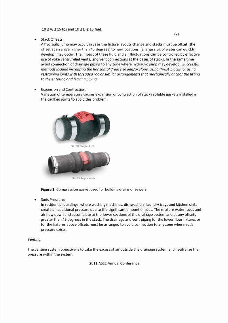
Expansion and Contraction:
Variation of temperature causes expansion or contraction of stacks soluble gaskets installed in
the caulked joints to avoid this problem.
Figure 1. Compression gasket used for building drains or sewers
Suds Pressure:
In residential buildings, where washing machines, dishwashers, laundry trays and kitchen sinks
create an additional pressure due to the significant amount of suds. The mixture water, suds and
air flow down and accumulate at the lower sections of the drainage system and at any offsets
greater than 45 degrees in the stack. The drainage and vent piping for the lower floor fixtures or
for the fixtures above offsets must be arranged to avoid connection to any zone where sudspressure exists.
Venting:
The venting system objective is to take the excess of air outside the drainage system and neutralize the
pressure within the system.

7/27/2019 Eaching High-rise Plumbing Design
http://slidepdf.com/reader/full/eaching-high-rise-plumbing-design 7/19
2011 ASEE Annual Conference
Case Study:
In this part, we present a case study developed by the students. The objective of this project is to
convert an existing plumbing of a commercial building is China to fulfill the international plumbing code
(2009), as well as international building code (2009). The actual code is the Chinese code. The
methodology followed is as follow:
1) Determination of the number of building occupants and the minimum number of plumbing
fixtures floor by floor
2) Sizing the drain, waste and vent systems
3) Domestic water system load
4) Domestic water system size.
5) Special design of this building
6) Comparison between the Chinese design and the design according to the international codes.
This process is represented in the Figure 1. The building is a high-rise, 15 story office building, with 4
stacks. The floor plan of the basement floor is represented in Figure 2.
7/27/2019 Eaching High-rise Plumbing Design
http://slidepdf.com/reader/full/eaching-high-rise-plumbing-design 8/19
2011 ASEE Annual Conference
7/27/2019 Eaching High-rise Plumbing Design
http://slidepdf.com/reader/full/eaching-high-rise-plumbing-design 9/19
2011 ASEE Annual Conference
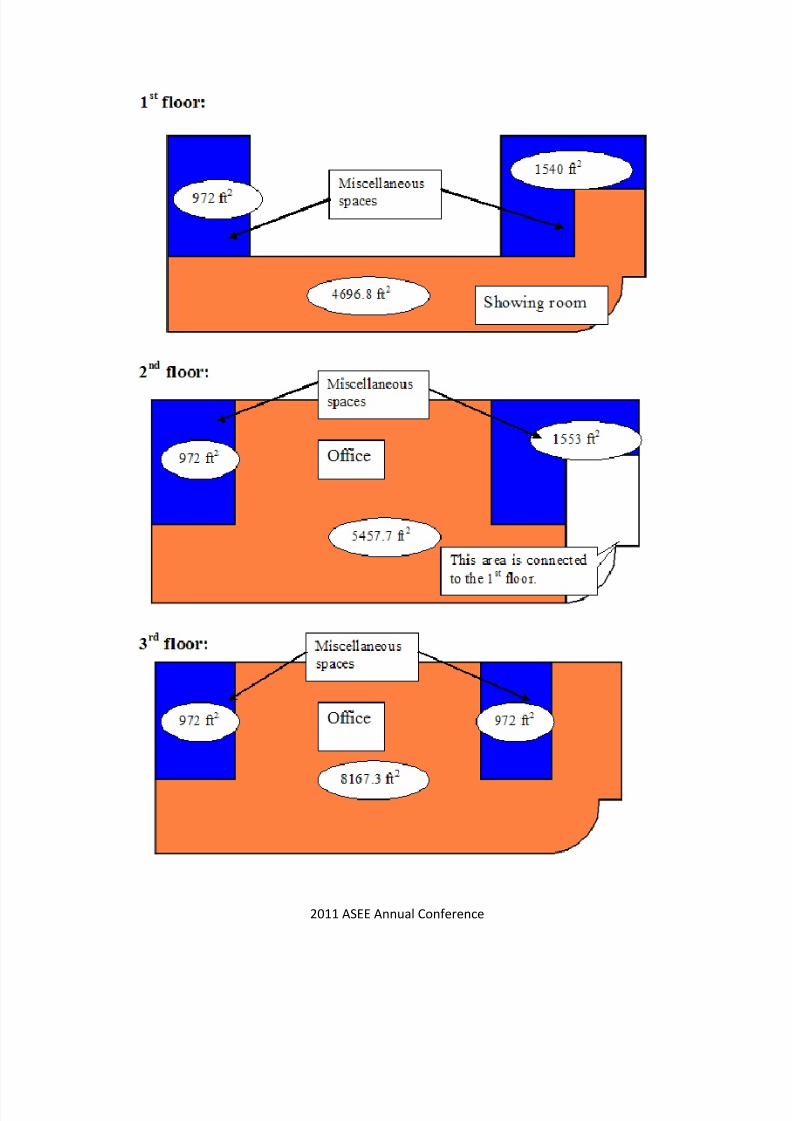
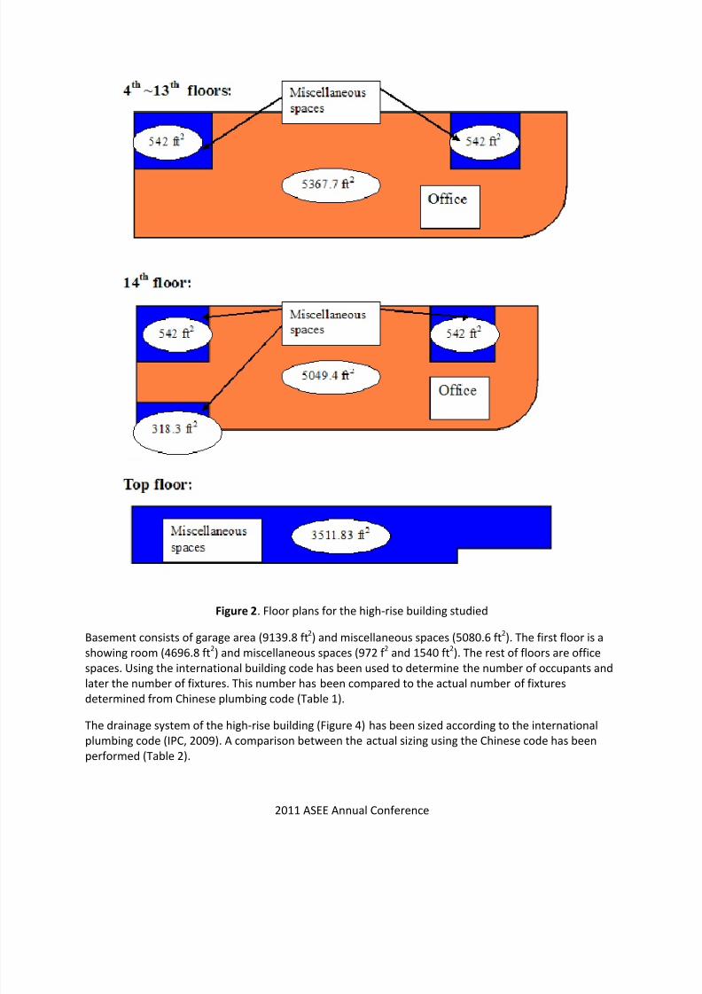
Figure 2. Floor plans for the high-rise building studied
Basement consists of garage area (9139.8 ft2) and miscellaneous spaces (5080.6 ft
2). The first floor is a
showing room (4696.8 ft2) and miscellaneous spaces (972 f
2and 1540 ft
2). The rest of floors are office
spaces. Using the international building code has been used to determine the number of occupants and
later the number of fixtures. This number has been compared to the actual number of fixtures
determined from Chinese plumbing code (Table 1).
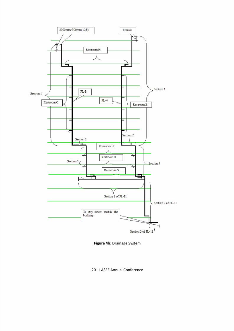
The drainage system of the high-rise building (Figure 4) has been sized according to the international
plumbing code (IPC, 2009). A comparison between the actual sizing using the Chinese code has been
performed (Table 2).

7/27/2019 Eaching High-rise Plumbing Design
http://slidepdf.com/reader/full/eaching-high-rise-plumbing-design 10/19
2011 ASEE Annual Conference
Figure 3. Flow chart used to compare the actual design (China) to IPC (2009)
BEGIN
Determination of total coincidental
peak load demand (CPLD)
Size the domestic water system
(IPC, 2009)
Actual sizes equal
to the sizesRedesign the water system
Propose a venting system
Size the drain, waste and vent systems
Actual sizes equal
to the sizes
Use the larger size
END
NO
NO
YES
YES
7/27/2019 Eaching High-rise Plumbing Design
http://slidepdf.com/reader/full/eaching-high-rise-plumbing-design 11/19
2011 ASEE Annual Conference
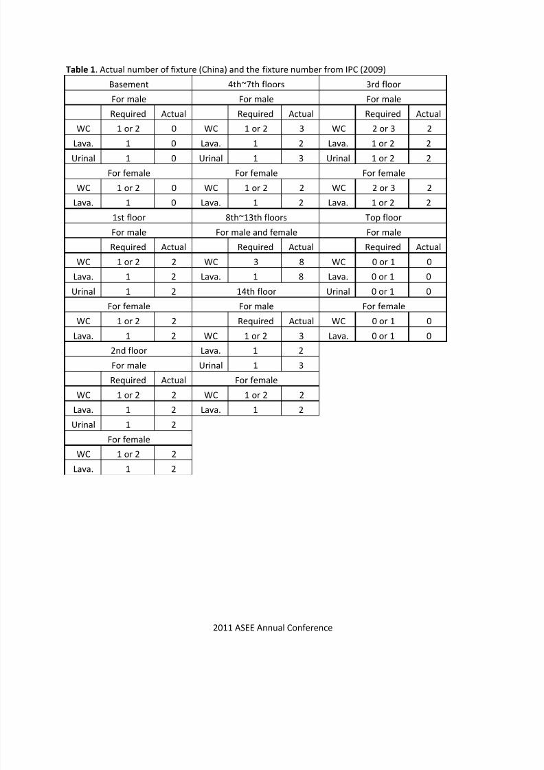
Table 1. Actual number of fixture (China) and the fixture number from IPC (2009)
Basement 4th~7th floors 3rd floor
For male For male For male
Required Actual Required Actual Required Actual
WC 1 or 2 0 WC 1 or 2 3 WC 2 or 3 2
Lava. 1 0 Lava. 1 2 Lava. 1 or 2 2
Urinal 1 0 Urinal 1 3 Urinal 1 or 2 2
For female For female For female
WC 1 or 2 0 WC 1 or 2 2 WC 2 or 3 2
Lava. 1 0 Lava. 1 2 Lava. 1 or 2 2
1st floor 8th~13th floors Top floor
For male For male and female For male
Required Actual Required Actual Required Actual
WC 1 or 2 2 WC 3 8 WC 0 or 1 0
Lava. 1 2 Lava. 1 8 Lava. 0 or 1 0
Urinal 1 2 14th floor Urinal 0 or 1 0
For female For male For female
WC 1 or 2 2 Required Actual WC 0 or 1 0
Lava. 1 2 WC 1 or 2 3 Lava. 0 or 1 0
2nd floor Lava. 1 2
For male Urinal 1 3
Required Actual For female
WC 1 or 2 2 WC 1 or 2 2
Lava. 1 2 Lava. 1 2
Urinal 1 2
For female
WC 1 or 2 2
Lava. 1 2

7/27/2019 Eaching High-rise Plumbing Design
http://slidepdf.com/reader/full/eaching-high-rise-plumbing-design 12/19
2011 ASEE Annual Conference
Figure 4a: Drainage System
7/27/2019 Eaching High-rise Plumbing Design
http://slidepdf.com/reader/full/eaching-high-rise-plumbing-design 13/19
2011 ASEE Annual Conference
Figure 4b: Drainage System

7/27/2019 Eaching High-rise Plumbing Design
http://slidepdf.com/reader/full/eaching-high-rise-plumbing-design 14/19
2011 ASEE Annual Conference
Figure 4c: Drainage System

7/27/2019 Eaching High-rise Plumbing Design
http://slidepdf.com/reader/full/eaching-high-rise-plumbing-design 15/19
2011 ASEE Annual Conference
Figure 4d: Drainage System

7/27/2019 Eaching High-rise Plumbing Design
http://slidepdf.com/reader/full/eaching-high-rise-plumbing-design 16/19
2011 ASEE Annual Conference
Table 2. Results of the comparison between the actual building (China) and the IPC (2009):
Section of pipe Definition DFU
Mini. Size
(inch)
Actual
Table used
Modified size
(inch)size(inch)
Section 1 of PL 1 Stack 72 4 4 Table 6-2 6
Section 2 of PL 1 Building drain 72 4 4 Table 6-1 6
Section 1 of PL 2 Stack 36 21/2
4 Table 6-2 6
Section 2 of PL 2 Building drain 36 4 6 Table 6-1
Section 1 of PL 3 Stack 36 21/2
4 Table 6-2 6
Section 2 of PL 3 Building drain 36 4 6 Table 6-1
Section 1 of PL 4 Stack 53 4 4 Table 6-2 6
Section 2 of PL 4 Building drain 53 4 4 Table 6-1 6
Section 3 of PL 4 Stack 98 4 4 Table 6-2 6
Section 1 of PL 5 Stack 36 21/2
4 Table 6-2
Section 2 of PL 5 Building drain 36 4 4 Table 6-1 6
Section 3 of PL 5 Stack 36 4 4 Table 6-2 6
Section 4 of PL 5 Building drain 36 4 4 Table 6-1 6
Section 1 of PL 6 Stack 36 21/2 4 Table 6-2 6
Section 2 of PL 6 Building drain 36 4 6 Table 6-1
Section 1 of PL 7 Stack 36 21/2
4 Table 6-2 6
Section 2 of PL 7 Building drain 36 4 6 Table 6-1
Section 1 of PL 8 Stack 70 4 4 Table 6-2 6
Section 2 of PL 8 Building drain 70 4 4 Table 6-1 6
Section 3 of PL 8 Stack 142 4 4 Table 6-2 6
Section 1 of PL 9 Stack 60 4 4 Table 6-2 6
Section 2 of PL 9 Building drain 60 4 4 Table 6-1 6
Section 3 of PL 9 Stack 60 4 4 Table 6-2 6
Section 4 of PL 9 Building drain 60 4 4 Table 6-1 6
Section 1 of PL 10 Building drain 144 4 6 Table 6-1
Section 2 of PL 10 Stack 144 4 6 Table 6-2
Section 3 of PL 10 Building drain 144 4 6 Table 6-1
Section 1 of PL 11 Building drain 240 5 6 Table 6-1 8
Section 2 of PL 11 Stack 240 5 6 Table 6-2 8
Section 3 of PL 11 Building drain 240 5 6 Table 6-1 8
Section 1 of PL 13 Stack 16 2 21/2
Table 6-2 3
Section 2 of PL 13 Building drain 16 3 21/2 Table 6-1 4
7/27/2019 Eaching High-rise Plumbing Design
http://slidepdf.com/reader/full/eaching-high-rise-plumbing-design 17/19
2011 ASEE Annual Conference
Evaluating Student Performance
Student performance in this specific course is evaluated, and their progress is monitored, by the
instructor, who will assign a grade for the course. Although varied to a limited extent, the assignment of
the grade is generally based on (a) homework problems, (b) quizzes and mid-tem exams, (c) final exam,
(d) project, and (e) other assignments including presentation of projects, which is required in this
course.
This course requires a group project involving a complete design that may contain a host of modules
including architectural plumbing drawings, hot/cold water design, drainage/venting system, cost
estimating and bid document preparation, etc. This course is a multi-disciplinary effort; and as such our
objective is to make involve students from other disciplines in addition to those in architectural
engineering. The student performance in this course is evaluated through weekly progress reports by
students, mid-term presentation of project progress, final presentation of the project (power point
presentation and poster presentation), examination on the learning objectives, results of ethics study
(including preparation of a code of ethics by students), and preparation of a complete project report
that contains all design drawings and calculations. This course also involve leadership and oral and
writing components as part of their learning objectives.
The student performance in courses involving laboratory also includes evaluation of laboratory reports
required from students. Grading of laboratory reports is rigorous and involves evaluation of technical
contents, clarity and coherence of presented materials, and writing skills.
Most of the architectural engineering senior level courses also involve projects. In addition to homework
problems, exams, etc. the student evaluation in these courses is also achieved through review of their
final project reports and in some cases the oral presentation of their work.
Future plans to evaluate the effectiveness of the curriculum in term of learning outcomes:
Actions that will be implemented to improve the effectiveness of the curriculum in term of learning
outcomes:
We expanded on the instructors’ self-evaluation such that more direct assessment of students’
learning outcomes is obtained. A set of standards for instructor’s self-evaluation will be
prepared by the faculty and the Board of Advisors and will be implemented with the annual
assessment cycle. The main point of these standards is that the evaluation of students’
performance will based on samples of work in three categories of students: those in the upper
75 percentile, those in the 50 – 75 percentile and those below the 50 percentile populations.
Thus the assessment results compiled are based on course performances and grades, exams,
projects, presentations of students, and writings as required in some courses. Furthermore,each course specifically addresses the learning outcomes and relation between the course and
the Program outcomes, the methods used for the evaluation of students’ performance and the
relevance of the course materials to the Program outcomes following the standards adopted for
the assessment process.
Students will be provided with the course descriptions including learning objectives and
outcomes. Students also will provide their input on the Program outcomes. The results from this
7/27/2019 Eaching High-rise Plumbing Design
http://slidepdf.com/reader/full/eaching-high-rise-plumbing-design 18/19
2011 ASEE Annual Conference
instrument are used along with those from the instructors’ self-assessment of courses as a
means to ensuring compatibility in results obtained.
A more rigorous process in assessing the learning outcomes of the capstone courses will be
implemented, which are in parallel with the Program outcomes. The following outlines process
will be used for the capstone course assessment.
o Individual instructor evaluation of the degree of learning achievement of individual
students on a capstone team, which includes consideration of the collective
achievements of the team.
o Peer evaluation (optional by instructor).
o Grading of deliverables by the instructors (project plan, mid-term review, final report,
exhibit (and abstract), oral presentation, team minutes, web site if applicable).
o Teamwork survey.
o Self-assessment.
o Senior Design Symposium judging (with evaluation criteria explicitly indexed to the
learning objectives and articulated via rubrics for all measures).
Conclusions:
High-rise buildings are challenging to build architecturally and also they are challenging in term of
engineering design, such as pumping cold and hot water, and mechanical uses, such as cooling towers
and supplying HVAC equipment. In this paper, we exposed the summary of the methodology followed to
teach high-rise plumbing.
A case study has been developed to demonstrate the difference between plumbing designs in other
countries, such as China where the venting system is not required. We presented the results of
comparison between the two codes.
This design class has been positively accepted by the students, and has provided them with a
comprehensive experience in both design and systems integration. Students are required to usemultiple codes and make the comparison between several designs and codes. Finally, it provides
the students an opportunity to improve their skills in both written and oral communication.
References:
1) Alfred Steele, 1984 “Advanced Plumbing Technology”, Steele Press, 299 pages.
2) Robert H. Thompson, “Design Considerations for Fire Pumps in High Rise Buildings, Part 2”,
October 5, 2006
3) JIM BEVERIDGE, P. ENG, “Domestic Water System Design for High-rise Buildings”, 2007, Vol. 6:
No. 3 (PSD)
4) High rise water distribution, Peter A. Kraut, P.E.
5) Dennis M. Connelly, “High-rise Plumbing Design”, 2007, PSD
6) Hot Water Recirculation in High-Rise Buildings, February 2010, Plumbing Engineer.

7/27/2019 Eaching High-rise Plumbing Design
http://slidepdf.com/reader/full/eaching-high-rise-plumbing-design 19/19
2011 ASEE Annual Conference
7) Wolfgang Osada, “Restoration of domestic water pipes in high-rise buildings”, March 2008.
8) Jonathan S. Ladd, 2005, “An Evaluation and Pressure-Driven Design of Potable Water Plumbing
Systems”.
9) Paul Larson, July 10, 2007 “ How to Properly Size a Domestic Water Pressure Booster System,
pme