E5EZ-PRRE5EZ-PRR - OMRON – Automação Industrial | … · 2016-07-01 · E5EZ-PRRE5EZ-PRR...
137
E5EZ-PRR E5EZ-PRR E5EZ-PRR E5EZ-PRR Position Proportional Controller User’s Manual Cat. No. H200-E1-01
Transcript of E5EZ-PRRE5EZ-PRR - OMRON – Automação Industrial | … · 2016-07-01 · E5EZ-PRRE5EZ-PRR...
E5EZ-PRRE5EZ-PRRE5EZ-PRRE5EZ-PRR
Position Proportional Controller
User’s Manual
Cat. No. H200-E1-01

Introduction
E5EZ-PRR Temperature Controller Features:Thank you for choosing the OMRON E5EZ-PRR. This user manual describes E5EZ-PRR features, performance, and necessary precautions.When using the E5EZ-PRR please carefully observe the following: The E5EZ-PRR should be used only by trained professionals; Read the instruction manual carefully before using, and following the instructions during use; Keep this manual for future reference.
For detailed explanations of communications functions please see E5AN/EN/CN/GN Temperature Controller Communications Manual (Cat.N0. H102). The E5EZ-PRR has similar communications functions.
© OMRON, 2006All rights reserved. No part of this document may be reproduced, transmitted or stored in any form or by any means, electronic or mechanical, for any purpose, without the express written permission of OMRON.Use of information contained herein does not affect patent rights. OMRON products are constantly being improved, and the information covered in this manual is subject to change without notice. Every effort was made to include all necessary information; but OMRON cannot be held responsible for losses incurred due to mistakes or omissions.
I

Read and Understand this Manual
Please read and understand this manual before using the product. Please consult your OMRONrepresentative if you have any questions or comments.
Warranty and Limitations of LiabilityWARRANTYOMRON's exclusive warranty is that the products are free from defects in materials and workmanship for aperiod of one year (or other period if specified) from date of sale by OMRON.OMRON MAKES NO WARRANTY OR REPRESENTATION, EXPRESS OR IMPLIED, REGARDING NON-INFRINGEMENT, MERCHANTABILITY, OR FITNESS FOR PARTICULAR PURPOSE OF THE PRODUCTS. ANY BUYER OR USER ACKNOWLEDGES THAT THE BUYER OR USER ALONE HAS DETERMINED THAT THE PRODUCTS WILL SUITABLY MEET THE REQUIREMENTS OF THEIR INTENDED USE. OMRON DISCLAIMS ALL OTHER WARRANTIES, EXPRESS OR IMPLIED.
LIMITATIONS OF LIABILITYOMRON SHALL NOT BE RESPONSIBLE FOR SPECIAL, INDIRECT, OR CONSEQUENTIAL DAMAGES, LOSS OF PROFITS OR COMMERCIAL LOSS IN ANY WAY CONNECTED WITH THE PRODUCTS, WHETHER SUCH CLAIM IS BASED ON CONTRACT, WARRANTY, NEGLIGENCE, OR STRICT LIABILITY.In no event shall the responsibility of OMRON for any act exceed the individual price of the product on which liability is asserted. IN NO EVENT SHALL OMRON BE RESPONSIBLE FOR WARRANTY, REPAIR, OR OTHER CLAIMS REGARDING THE PRODUCTS UNLESS OMRON'S ANALYSIS CONFIRMS THAT THE PRODUCTS WERE PROPERLY HANDLED, STORED, INSTALLED, AND MAINTAINED AND NOT SUBJECT TO CONTAMINATION, ABUSE, MISUSE, OR INAPPROPRIATE MODIFICATION OR REPAIR.
Application ConsiderationsSUITABILITY FOR USEOMRON shall not be responsible for conformity with any standards, codes, or regulations that apply to the combination of products in the customer's application or use of the products.At the customer's request, OMRON will provide applicable third party certification documents identifying ratings and limitations of use that apply to the products. This information by itself is not sufficient for a complete determination of the suitability of the products in combination with the end product, machine, system, or other application or use.The following are some examples of applications for which particular attention must be given. This is not intended to be an exhaustive list of all possible uses of the products, nor is it intended to imply that the uses listed may be suitable for the products: Outdoor use, uses involving potential chemical contamination or electrical interference, or conditions or uses not described in this manual. Nuclear energy control systems, combustion systems, railroad systems, aviation systems, medical equipment, amusement machines, vehicles, safety equipment, and installations subject to separate industry or government regulations. Systems, machines, and equipment that could present a risk to life or property. Please know and observe all prohibitions of use applicable to the products.NEVER USE THE PRODUCTS FOR AN APPLICATION INVOLVING SERIOUS RISK TO LIFE OR PROPERTY WITHOUT ENSURING THAT THE SYSTEM AS A WHOLE HAS BEEN DESIGNED TO ADDRESS THE RISKS, AND THAT THE OMRON PRODUCTS ARE PROPERLY RATED AND INSTALLED FOR THE INTENDED USE WITHIN THE OVERALL EQUIPMENT OR SYSTEM.
PROGRAMMABLE PRODUCTSOMRON shall not be responsible for the user's programming of a programmable product, or any consequence thereof.
II
DisclaimersCHANGE IN SPECIFICATIONSProduct specifications and accessories may be changed at any time based on improvements and other reasons.It is our practice to change model numbers when published ratings or features are changed, or when significant construction changes are made. However, some specifications of the products may be changed without any notice. When in doubt, special model numbers may be assigned to fix or establish key specifications for your application on your request. Please consult with your OMRON representative at any time to confirm actual specifications of purchased products.
DIMENSIONS AND WEIGHTSDimensions and weights are nominal and are not to be used for manufacturing purposes, even when tolerances are shown.
PERFORMANCE DATAPerformance data given in this manual is provided as a guide for the user in determining suitability and does not constitute a warranty. It may represent the result of OMRON's test conditions, and the users must correlate it to actual application requirements. Actual performance is subject to the OMRON Warranty and Limitations of Liability.
ERRORS AND OMISSIONSThe information in this document has been carefully checked and is believed to be accurate; however, no responsibility is assumed for clerical, typographical, or proofreading errors, or omissions.
III

Safety Precautions
Definition of Precautionary InformationThe following notation is used in this manual to provide precautions requiredto ensure safe usage of the product.
The safety precautions that are provided are extremely important to safety. Always read and heed the information provided in all safety precautions.
The following notation is used.
Symbols
CAUTIONIndicates a potentially hazardous situation which, if not avoided, is likely to result in minor or moderate injury or in property damage.
Symbol Meaning
Caution
General CautionIndicates non-specific general cautions, warnings, and dangers.
Electrical Shock CautionIndicates possibility of electric shock under specific conditions.
Prohibition
General ProhibitionIndicates non-specific general prohibitions.
Disassembly ProhibitionIndicates prohibitions when there is a possibility of injury, such as from electric shock, as the result of disassembly.
Mandatory Caution
General CautionIndicates non-specific general cautions, warnings, and dangers.
IV

Safety Precautions
*1 A SELV circuit is one separated from the power supply with double insulation or reinforced insulation,thatdoes not exceed 30 V r.m.s. and 42.4 V peak or 60VDC.
*2 A class 2 power supply is one tested and certified by UL as having the current and voltage of thesecondaryoutput restricted to specific levels.
CAUTION
Do not touch the terminals while power is being supplied.Doing so may occasionally result in minor injury due to electric shock.
Do not allow pieces of metal, wire clippings, or fine metallic shav-ings or filings from installation to enter the product. Doing so may occasionally result in electric shock, fire, or malfunction.
Do not use the product where subject to flammable or explosive gas. Otherwise, minor injury from explosion may occasionally occur.
Never disassemble, modify, or repair the product or touch any of the internal parts. Minor electric shock, fire, or malfunction may occasionally occur.
CAUTION - Risk of Fire and Electric Shocka)This product is UL listed as Open Type Process Control
Equip-ment. It must be mounted in an enclosure that does not allow fire to escape externally.
b)More than one disconnect switch may be required to de-energize the equipment before servicing the product.
c)Signal inputs are SELV, limited energy.*1d)Caution: To reduce the risk of fire or electric shock, do not
inter-connect the outputs of different Class 2circuits.*2
If the output relays are used past their life expectancy, contact fusing or burning may occasionally occur.Always consider the application conditions and use the output relays within their rated load and electrical life expectancy. The life expectancy of output relays varies considerably with the output load and switching conditions.
V

CAUTION
Tighten the terminal screws to between 0.74 and 0.90 N·m. Loose screws may occasionally result in fire. (See note.)
Set the parameters of the product so that they are suitable for the system being controlled. If they are not suitable, unexpected operation may occasionally result in property damage or accidents.
A malfunction in the Temperature Controller may occasionally make control operations impossible or prevent alarm outputs, resulting in property damage. To maintain safety in the event of malfunction of the Temperature Controller, take appropriate safety measures, such as installing a monitoring device on a separate line.
A semiconductor is used in the output section of long-life relays. If excessive noise or surge is impressed on the output terminals, a short-circuit failure is likely to occur. If the output remains shorted, fire will occur due to overheating of the heater or other cause. Take measures in the overall system to prevent excessive temper-ature increase and to prevent fire from spreading.
VI
Precautions for Safe Use
Be sure to observe the following precautions to prevent operation failure, malfunction, or adverse affects onthe performance and functions of the product. Not doing so may occasionally result in unexpected events.(1) The product is designed for indoor use only. Do not use the product outdoors or in any of the
followinglocations.• Places directly subject to heat radiated from heating equipment.• Places subject to splashing liquid or oil atmosphere.• Places subject to direct sunlight.• Places subject to dust or corrosive gas (in particular, sulfide gas and ammonia gas).• Places subject to intense temperature change.• Places subject to icing and condensation.• Places subject to vibration and large shocks.
(2) Use and store the Digital Temperature Controller within the rated ambient temperature and humidity. Gang-mounting two or more temperature controllers, or mounting temperature controllers above each other may cause heat to build up inside the temperature controllers, which will shorten their service life. Insuch a case, use forced cooling by fans or other means of air ventilation to cool down the Digital Temperature Controllers.
(3) To allow heat to escape, do not block the area around the product. Do not block the ventilation holes onthe product.
(4) Be sure to wire properly with correct polarity of terminals.(5) Use the specified size (M3.5, width 7.2 mm or less) crimped terminals for wiring. For open-wiredconnection,
use stranded or solid copper wires with a gage of AWG24 to AWG14 (equal to a cross-sectional area of
0.205 to 2.081 mm2). (The stripping length is 5 to 6 mm.) Up to two wires or two crimpterminals can be inserted into a single terminal.
(6) Do not wire the terminals which are not used.(7) To avoid inductive noise, keep the wiring for the Digital Temperature Controller's terminal block away from
power cables carry high voltages or large currents. Also, do not wire power lines together with or parallel to Digital Temperature Controller wiring. Using shielded cables and using separate conduits or ducts is recommended.Attach a surge suppressor or noise filter to peripheral devices that generate noise (in particular, motors, transformers, solenoids, magnetic coils or other equipment that have an inductance component). When a noise filter is used at the power supply, first check the voltage or current, and attach the noise filter as close as possible to the temperature controller.Allow as much space as possible between the Digital Temperature Controller and devices that generate powerful high frequencies (high-frequency welders, high-frequency sewing machines, etc.) or surge.
(8) Use this product within the rated load and power supply.(9) Make sure that the rated voltage is attained within two seconds of turning ON the power using a switch or
relay contact. If the voltage is applied gradually, the power may not be reset or output malfunctions may occur.
(10) Make sure that the Temperature Controller has 30 minutes or more to warm up after turning ON the power before starting actual control operations to ensure the correct temperature display.
(11) When executing self-tuning, turn ON power for the load (e.g., heater) at the same time as or before supplying power to the Digital Temperature Controller. If power is turned ON for the Digital Temperature Controller before turning ON power for the load, self-tuning will not be performed properly and optimum control will not be achieved.
(12) A switch or circuit breaker should be provided close to this unit. The switch or circuit breaker should be within easy reach of the operator, and must be marked as a disconnecting means for this unit.
(13) Always turn OFF the power supply before pulling out the interior of the product, and never touch nor apply shock to the terminals or electronic components. When inserting the interior of the product, do not allow the electronic components to touch the case.
VII

(14) Do not use paint thinner or similar chemical to clean with. Use standard grade alcohol.(15) Design system (control panel, etc) considering the 2 second of delay that the controller's output to be set
after power ON.(16) The output may turn OFF when shifting to certain levels. Take this into consideration when performing
control.(17) The number of EEPROM write operations is limited. Therefore, use RAM write mode when frequently
overwriting data during communications or other operations.
Service LifeUse the Temperature Controller within the following temperature and humidity ranges:Temperature: -10 to 55°C (with no icing or condensation), Humidity: 25% to 85%If the Controller is installed inside a control board, the ambient temperature must be kept to under 55°C, including the temperature around the Controller.The service life of electronic devices like Temperature Controllers is determined not only by the num-ber of times the relay is switched but also by the service life of internal electronic components. Component service life is affected by the ambient temperature: the higher the temperature, the shorter the service life and, the lower the temperature, the longer the service life. Therefore, the service life can be extended by lowering the temperature of the Temperature Controller.When two or more Temperature Controllers are mounted horizontally close to each other or vertically next to one another, the internal temperature will increase due to heat radiated by the Temperature Controllers and the service life will decrease. In such a case, use forced cooling by fans or other means of air ventilation to cool down the Temperature Controllers. When providing forced cooling, however, be careful not to cool down the terminals sections alone to avoid measurement errors.
Ambient NoiseTo avoid inductive noise, keep the wiring for the Digital Temperature Controller's terminal block wiring away from power cables carrying high voltages or large currents. Also, do not wire power lines together with or parallel to Digital Temperature Controller wiring. Using shielded cables and using separate conduits or ducts is recommended.Attach a surge suppressor or noise filter to peripheral devices that generate noise (in particular, motors, transformers, solenoids, magnetic coils or other equipment that have an inductance compo-nent). When a noise filter is used at the power supply, first check the voltage or current, and attach the noise filter as close as possible to the Temperature Controller.Allow as much space as possible between the Digital Temperature Controller and devices that gener-ate powerful high frequencies (high-frequency welders, high-frequency sewing machines, etc.) or surge.
Ensuring Measurement AccuracyWhen extending or connecting the thermocouple lead wire, be sure to use compensating wires thatmatch the thermocouple types.When extending or connecting the lead wire of the platinum resistance thermometer, be sure to use Mount the Temperature Controller so that it is horizontally level.If the measurement accuracy is low, check to see if input shift has been set correctly.
WaterproofingThe degree of protection is as shown below. Sections without any specification on their degree of protection or those with IP0 are not waterproof.Front panel: NEMA4X for indoor use (equivalent to IP66)Rear case: IP20, Terminal section: IP00
VIII
Precautions for Operation
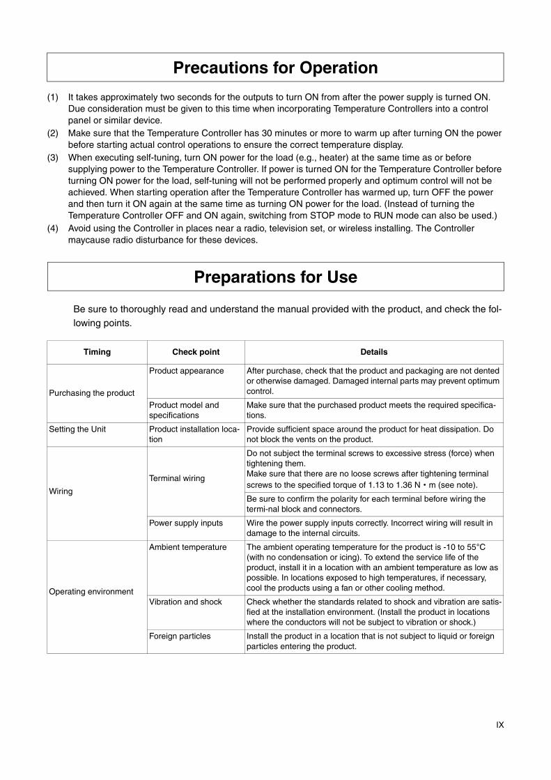
(1) It takes approximately two seconds for the outputs to turn ON from after the power supply is turned ON. Due consideration must be given to this time when incorporating Temperature Controllers into a control panel or similar device.
(2) Make sure that the Temperature Controller has 30 minutes or more to warm up after turning ON the power before starting actual control operations to ensure the correct temperature display.
(3) When executing self-tuning, turn ON power for the load (e.g., heater) at the same time as or before supplying power to the Temperature Controller. If power is turned ON for the Temperature Controller before turning ON power for the load, self-tuning will not be performed properly and optimum control will not be achieved. When starting operation after the Temperature Controller has warmed up, turn OFF the power and then turn it ON again at the same time as turning ON power for the load. (Instead of turning the Temperature Controller OFF and ON again, switching from STOP mode to RUN mode can also be used.)
(4) Avoid using the Controller in places near a radio, television set, or wireless installing. The Controller maycause radio disturbance for these devices.
Preparations for Use
Be sure to thoroughly read and understand the manual provided with the product, and check the fol-lowing points.
Timing Check point Details
Purchasing the product
Product appearance After purchase, check that the product and packaging are not dented or otherwise damaged. Damaged internal parts may prevent optimum control.
Product model and specifications
Make sure that the purchased product meets the required specifica-tions.
Setting the Unit Product installation loca-tion
Provide sufficient space around the product for heat dissipation. Do not block the vents on the product.
Wiring
Terminal wiring
Do not subject the terminal screws to excessive stress (force) when tightening them.Make sure that there are no loose screws after tightening terminal screws to the specified torque of 1.13 to 1.36 N·m (see note).
Be sure to confirm the polarity for each terminal before wiring the termi-nal block and connectors.
Power supply inputs Wire the power supply inputs correctly. Incorrect wiring will result in damage to the internal circuits.
Operating environment
Ambient temperature The ambient operating temperature for the product is -10 to 55°C (with no condensation or icing). To extend the service life of the product, install it in a location with an ambient temperature as low as possible. In locations exposed to high temperatures, if necessary, cool the products using a fan or other cooling method.
Vibration and shock Check whether the standards related to shock and vibration are satis-fied at the installation environment. (Install the product in locations where the conductors will not be subject to vibration or shock.)
Foreign particles Install the product in a location that is not subject to liquid or foreign particles entering the product.
IX

Conventions Used in This Manual
Meanings of abbreviationsThe following abbreviations are used in parameter names, figures, and in the text.Their meanings are explained below:
*1 “EU” represents one engineering unit. EU (e.g. °C, m, or, g) indicates the smallest engineering unit. EU size depends on input type. For example, when input temperature range is set to -200°C ~ +1300°C, 1EU is 1°C; and when input temperature range is set to -20.0°C ~ 500.0°C, 1EU is 0.1°C. With analog input, EU varies according to the decimal point of the scaling setting, and 1 EU becomes the smallest scaling unit.
Distinguishing CharactersThe following table shows the relationship between the character and letter symbols as displayed on the monitor.
Symbol Term
PVPresent value (displayed as “PV” on the panel)
SPSet point (displayed as “SV” on the panel)
SV Set value
MV Valve percent open
AT Auto-tuning
EU Engineering unit *1
a b c d e f g h i j k l m
A B C D E F G H I J K L M
n o p q r s t u v w x y z
N O P Q R S T U V W X Y Z
8888
8888
8888
PV
ALM1
OUT1 OUT2
ALM2
SV
MV
STOP CMW MANU
X

How to use this manual
Objective Related titles Description
Understanding the E5EZ-PRR Chapter OneIntroduction
This chapter describes the fea-tures, names, and typical func-tions of each component.
Configuring the E5EZ-PRR Chapter Two Preparing for Operation
This chapter describes installa-tion and wiring procedures.
Basic Operation Chapter ThreeBasic OperationChapter FiveParameters
These two chapters give exam-ples of basic controls.
Operation Applications Chapter FourOperation ApplicationsChapter FiveParameters
These two chapters describe how to use the E5EZ-PRR’s advanced functions.
Appendix This chapter describes unit specifications. The attached parameter table can serve as a parameter setting reference.
XI
Content
Content
Introduction............................................................. I
Read and Understand this Manual ........................ II
Precautions for Safe Use.....................................VII
Precautions for Operation.....................................IX
Preparations for Use.............................................IX
Conventions Used in This Manual.........................X
Chapter 1 Overview......................................................................................... 1-11.1 Name of Parts..............................................................................................................1-2
E5EZ-PRR Front Panel ............................................................................................................1-2Display......................................................................................................................................1-3Using the Keys .........................................................................................................................1-3
1.2 Input/Output Configuration and Main Functions ..........................................................1-4Input/Output Configuration .......................................................................................................1-4Main Functions .........................................................................................................................1-5
1.3 Setting Level Configuration and Panel Key Operations ..............................................1-6Select Parameters ....................................................................................................................1-8Fixed Settings...........................................................................................................................1-8
1.4 Communications Functions .........................................................................................1-9
Chapter 2 Setup .............................................................................................. 2-12.1 Installation ...................................................................................................................2-2
E5EZ-PRR Dimensions ............................................................................................................2-2E5EZ-PRR Panel Cutout ..........................................................................................................2-2E5EZ-PRR Assembly ...............................................................................................................2-3Installing the E5EZ-PRR onto Panel ........................................................................................2-3
2.2 Wiring Terminals..........................................................................................................2-4E5EZ-PRR Wiring.....................................................................................................................2-4Wires Connecting Notice ..........................................................................................................2-4Connecting Wires .....................................................................................................................2-5Event Input ...............................................................................................................................2-6Communications.......................................................................................................................2-6
2.3 Installation Requirements ............................................................................................2-8Ensuring Long Service Life.......................................................................................................2-8Decreasing Noise .....................................................................................................................2-8Ensuring High Accuracy Measurement ....................................................................................2-8
Chapter 3 Basic Operations ............................................................................ 3-13.1 Initial Setting Samples .................................................................................................3-23.2 Set Input Type .............................................................................................................3-4
Input Type.................................................................................................................................3-43.3 Selecting °C/°F ............................................................................................................3-6
Temperature Unit......................................................................................................................3-63.4 Setting Output Specifications ......................................................................................3-7
Direct/reverse Operation ..........................................................................................................3-73.5 SP Setting....................................................................................................................3-9
SP Modifying ............................................................................................................................3-9
I

3.6 Verifying PID Constants (AT and manual settings) ...................................................3-10AT (auto-tuning)......................................................................................................................3-10Manual Settings......................................................................................................................3-12
3.7 Alarm Output .............................................................................................................3-14Alarm Type .............................................................................................................................3-14Alarm Value ............................................................................................................................3-15Alarm Delay ............................................................................................................................3-16
3.8 Ceramic Kiln Setting Position Proportional Control ...................................................3-17Application Examples .............................................................................................................3-17Wiring .....................................................................................................................................3-18Settings...................................................................................................................................3-18Adjustment..............................................................................................................................3-19Fixed settings for position proportional control .......................................................................3-20
3.9 During Manual Control...............................................................................................3-213.10 Operation Requirements ...........................................................................................3-22
Chapter 4 Applied Operations ......................................................................... 4-14.1 Input Shift Values ........................................................................................................4-2
Input Shift .................................................................................................................................4-2Calculating Input Shift Values (2 Point Shift)............................................................................4-31 Point Shift Method .................................................................................................................4-42 Point Shift Method .................................................................................................................4-42 Point Temperature Input Shift Example.................................................................................4-5
4.2 Alarm Hysteresis .........................................................................................................4-6Standby Sequence ...................................................................................................................4-6Standby Sequence Restart.......................................................................................................4-6Alarm Latch ..............................................................................................................................4-6Shutdown on Alarm /Alarm Activation ......................................................................................4-7Alarm Operation Overview .......................................................................................................4-7Alarm Delay Function ...............................................................................................................4-8
4.3 Calibrating Upper and Lower Limits (Analog Signal Input)..........................................4-9Analog Signal Input ..................................................................................................................4-9
4.4 Using Event Input ......................................................................................................4-11Setting Event Input .................................................................................................................4-11Using Multiple Set Points........................................................................................................4-11Key Operation Settings...........................................................................................................4-12Setting ....................................................................................................................................4-12Using Run/Stop Control..........................................................................................................4-14
4.5 Setting SP Upper and Lower Limit Values ................................................................4-15Set Point Limits.......................................................................................................................4-15Settings...................................................................................................................................4-16
4.6 Using the SP Ramp Function (to limit rate of SP change)........................................4-17SP Ramp ................................................................................................................................4-17
4.7 Switching to the Advanced Function Level................................................................4-194.8 Using The Key Protection Level ................................................................................4-20
Key Protection ........................................................................................................................4-20
Chapter 5 Parameters ..................................................................................... 5-1Contents of This Chapter.............................................................................................5-2Definition of the symbols used in this chapter .............................................................5-2Parameter display........................................................................................................5-2Parameter explain order in this chapter.......................................................................5-2Manual Control Level...................................................................................................5-3Protect Level................................................................................................................5-5
II

Operation Level ...........................................................................................................5-7Adjustment Level .......................................................................................................5-12Initial Level.................................................................................................................5-20Advanced Function Level ..........................................................................................5-28Communications Level ..............................................................................................5-41
Appendix .........................................................................................................A-1Specifications......................................................................................................................... A-2
Ratings .......................................................................................................................................... A-2Characteristics............................................................................................................................... A-3
Error Display .......................................................................................................................... A-4Parameter operations table.................................................................................................... A-6Sensor input settings and indicator range............................................................................ A-10Setting Data List................................................................................................................... A-11Parameter Flow.................................................................................................................... A-12
Index..............................................................................................................A-15
III

IV

Chapter 1 Overview
Chapter 1 Overview
1.1 Name of Parts..................................................................................1-2E5EZ-PRR Front Panel................................................................1-2Display .........................................................................................1-3Using the Keys.............................................................................1-3
1.2 Input/Output Configuration and Main Functions ..............................1-4Input/Output Configuration...........................................................1-4Main Functions ............................................................................1-5
1.3 Setting Level Configuration and Panel Key Operations ...................1-6Select Parameters .......................................................................1-8Fixed Settings ..............................................................................1-8
1.4 Communications Functions .............................................................1-9
1-1

Chapter 1 Overview
1.1 Name of Parts
E5EZ-PRR Front Panel
MANU
PV
SV
MV
AMMode key
Level key
Operation Indicators
Temperature Unit
No. 1 display
No. 2 display
No. 3 display
Operation Indicators
Down key
Auto/Manual
Up key
1-2

1.1 Name of Parts
1-3
Display No. 1 Display Displays process value and setting types.
All display segments light up for one second at startup. No. 2 Display Displays the set point, reading values, and input values. No. 3 Display When “valve opening display” is set to ON, displays the percentage of valve
opening. When “valve opening display” is set to OFF nothing will be displayed. (for “value opening display”, see page 5-40.) During parameter set-up No.3 displays the current level.
Operation Indicator Lights
(1) ALM1 (alarm 1)
When the alarm 1 output is ON, this light will come on.ALM2 (alarm 2) When the alarm 2 output is ON, this light will come on.
(2) OUT1, OUT2 (control output 1 (OPEN) , control output 2 (CLOSE) )
When control output 1/control output 2 is ON, the light will come on.
(3) STOP (stop)
The light comes on when operation stops.During opreration, when the event or run/stop setting stops, the light will come on.
(4) CMW (communications writing control)
The light comes on with communications writing “starts” and goes off when communications writing “stops”.
(5) MANU (manual control)
The light comes on during 「manual mode」 and goes off during 「automatic
mode」 .
Temperature Unit
When the display unit parameter is set to temperature, the temperature unit will be displayed. Current “temperature unit” data settings will be displayed. When this parameter is set to “°C ”, “C” will be displayed; when it is set to “°F”,“F” will be displayed.
Using the KeysThe basic function of the panel keys are described below.
(level) key Press to select setting level. Levels appear in the following sequence: “operations level”, ←→ “adjustment level”, “initial settings level”, ←→“communications level”
M (mode) key This key is used to select parameters for each level.
U (up) key Each press of this key increases values displayed on the No. 2 display, with the rate of increase proportional to the time the key is held down. In 「manual mode」 , pressing U turns the output 1 (OPEN output) ON.
D (down) key Each press of this key decreases values displayed on the No. 2 display with the rate of increase proportional to the time the key is held down. In 「manual mode」 , pressing D turns the output 2 (CLOSE output) ON.
A (manual/automatic) key
Manual/automatic switch key, switches between “manual mode” and “automatic mode”. Holding this button for 1 second or more (regardless of how long to let go) changes the mode.
+M group key
The group key accesses the E5EZ-PRR “protect level”. For details on the protect level, please see Chapter Five “Parameters”.

Chapter 1 Overview
1.2 Input/Output Configuration and Main Functions
Input/Output Configuration
Temperature Input /Analog singnal input
Potentiometer Input
Controller
Input from position proportional motor feedback resistance
Out 1
Out 2
ALM 2
ALM 1
Event Input2ch
Control output 1(OPEN Output)
Control output 2(CLOSE Output)
Alarm 2
Control output 1
Control output 2
Alarm output 2
Alarm output 1
Alarm 1
Input error
Communication function
External digital switch to change target set point value or Start/Stop
E5EZ-PRR
01 : RS232C
03 : RS485
Input type T : Thermocouple/non-contact temperature sensor/
L : Analog input (current input/voltage input)
Types of platinum resistance input
Select B : Event input (2 points)
1-4

1.2 Input/Output Configuration and Main Functions
Main FunctionsThe main functions of the E5EZ-PRR are discussed below. The details of each function and their uses are detailed from Chapter Three on.
Input Sensor Types
Temperature input (T) can be connected to the following input sensors:
Platinum resistanc:Pt100, JPt 100
Thermocouple :K, J, T, E, L, U, N, R, S, BNon-contact Temperature Sensor ES1B
: 10°C~70°C, 60°C~120°C, 115°C~165°C, 140°C~260°CAnalog signal input:0~50mV
Analog input (L) can be connected using the following input specifications:
Electric current input: DC4~20mA, DC0~20mAVoltage input: DC1~5V, DC0~5V, DC0~10V
Control Output E5EZ-PRR models control the output using relays.
Alarms Setting alarm type, alarm values, and upper and lower limit alarms. If necessary the “standby sequence”, “alarm hysteresis”, “alarm delay” and
“alarm off/alarm on” alarm latch parameters may be used for more complete alarm functions.
When input error output is set to “ON”, any errors will register on alarm output 1.
Control Tuning Optimal PID constants can be set easily with AT (auto-tuning).
Position Proportional Control
Floating control or closed control can be selected. Floating control can be used with or without potentiometer feedback during position proportional control.
Event Input The E5EZ-PRR2B , can access the following functions via event input:Selection of a variety of settings (a maximum of 4 setting points) and run/stop functions.
Communication Functions
Models with communication capabilities can communicate via CompoWay/F*1 or Sysway.E5EZ-PRR203 : RS-485 interface
E5EZ-PRR201 : RS-232C interface *1 CompoWay/F is a serial based communication protocol developed by OMRON using unified standards. CompoWay/F uses commands in compliance with FINS standards, and uses the same frame format as OMRON’s programmable controller to communicate with prior computers and components.
1-5
Chapter 1 Overview
1.3 Setting Level Configuration and Panel Key Operations
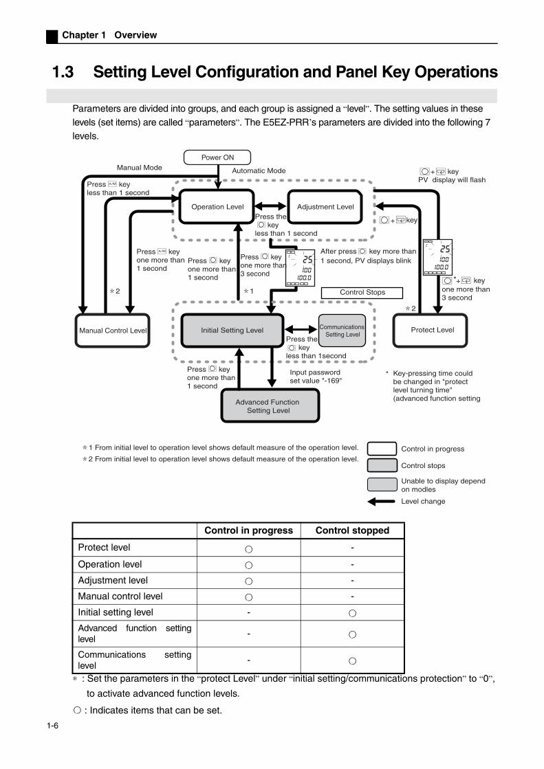
Parameters are divided into groups, and each group is assigned a “level”. The setting values in these levels (set items) are called “parameters”. The E5EZ-PRR’s parameters are divided into the following 7 levels.
∗ : Set the parameters in the “protect Level” under “initial setting/communications protection” to “0”,
to activate advanced function levels.
: Indicates items that can be set.
Control in progress Control stopped
Protect level -
Operation level -
Adjustment level -
Manual control level -
Initial setting level -
Advanced function settinglevel
-
Communications settinglevel
-
25
100
c
25
100
c
L
L
L
L
Operation Level Adjustment Level
L
key
After press key more than 1 second, PV displays blink
keyPV display will flash
key
Manual Control Level Initial Setting Level
Advanced Function Setting Level
Communications Setting Level
Protect Level
Control Stops
Input password set value "-169"
Control in progress
Control stops
Unable to display dependon modles
Level change
1 From initial level to operation level shows default measure of the operation level.
2 From initial level to operation level shows default measure of the operation level.
2 1
+
+
+
2
100.0
100.0
M
M
M
Power ONManual Mode Automatic Mode
Press A key less than 1 second
Press A key one more than 1 second
Press key one more than 1 second
LPress key one more than 3 second
LPress key one more than 1 second
L
Press the key less than 1 second
L
Press the key less than 1second
Key-pressing time could be changed in "protect level turning time" (advanced function setting
*
one more than 3 second
1-6

1.3 Setting Level Configuration and Panel Key Operations
Of these levels, the initial setting level, communications level, and advanced functions level may only be used when control has stopped. Please note that when selecting any of these three levels, controller output will stop.Unless the operation level is being displayed, the current level will be displayed.When settings are being changed, the No. 3 display will show the following:
Protect Level To switch to this level, you must press and hold the and M keys for 3 or more seconds. Protect level is used to prevent any unnecessary or accidental changes to the parameters. Protected levels are not displayed, so parameters located in these protected levels cannot be changed.* The key’s timing can be changed under “Protect level change time” (advanced function level).
Operation Level When the power is turned on this level is displayed. From this level the protect level , the initial setting level, and adjustment level can be accessed.
During operation process value and set point can be monitored, and set point, alarm values, and upper/lower alarm limits can be monitored and changed.
Adjustment Level
To access this level, press and hold the key for less than 1 second. Input from this level is used in control settings and offset values. The level
contains parameters used to set AT (auto-tuning), communications writing activation/deactivation hysteresis, various setting values, input shift values and PID constants. The uppermost parameters of the initial settings level, protect level, and operation level can be accessed from this level.
Manual Control Level
Pushing the A key under the operation/adjustment level for 1 second or more will activate manual mode, and switch to the manual control level. Under manual control, only “process value/setting value/valve open percentage (manual MV)” can be displayed. Under the “process value/set value/valve open percentage (manual MV)” manual control level, pressing the A key for 1 second or more will switch to automatic mode, switch to the operation level, display the level’s initial data, and allow manual operation of MV in this mode.
Initial Settings Level
To access this level, press the key for 3 or more seconds in the operation level or adjustment level. 1 second later, the PV display will blink. This level is used to indicate input type and select control method, control time, direct/reverse operation, and alarm type. You can move to the advanced function setting level or communications setting level from this level. Press the key for at least 1 second to switch to the operation level. Press the key for more than 1 second to switch to the communications level.
Advanced Function Level
To activate the advanced function setting level, set the “initial setting/communications protection” value under the “protect level” to “0”, then enter your password under the initial settings menu (“-169”).
The initial settings level can be accessed from this level. This level is used to set the display mode, and specify event input, standby
sequence, alarm hysteresis, and alarm delay.
Communications Level
To access this level, hold the key for less than 1 second under the initial settings menu. When the communications function is used, set the communications conditions in this level. When communicating with a personal computer (host), allow read and write set points and monitoring of operation volume.
No. 3 display Level nameManual MV Manual control levell.prt Protect levelNo display RUN levell.adj adjustment levell.ini input initial setting levell.com Communications setting levell.adv advanced function setting level
1-7

Chapter 1 Overview
Select Parameters Press M under any level to select parameters. A new parameter appears
each time M is pressed. For details about each parameter, see chapter 5.
Fixed Settings If the last parameter is reached and the M key is pressed again, the display
will return to the first parameter. To change a parameter’s setting or value the U or D keys may be used.
Wait for 2 seconds without changing or press the M key to fix the settings. When selecting another level, fix the parameters and settings on the display. When turning the power off, first fix the settings or parameters (by holding
the M key). In some cases settings cannot be changed by just holding down the U or D key.
1
2
3
n
Parameters
Parameters
Parameters
Parameters
1-8

1.4 Communications Functions
1.4 Communications Functions
E5EZ-PRR comes equipped with communications functions that allow monitoring of the controller and setting of parameters from a host computer. If communications functions are needed, please use a model equipped with these
functions (E5EZ-PRR201 or PRR203 ). For details on communications functions please see the E5AN/EN/CN/GN temperature controller (Communications Function User's Manuals).The communications functions on the E5EZ-PRR are similar.Access the communications level as follows.
(1) In the “Operations level”, hold down the button for 3 or more seconds.Access to the “Initial Settings Level”.
(2) Hold down the button for less than 1 second. From the “initial settings level”
access the “communications level”.
(3) Press the M key to access the next group of parameters.
(4) Press the U or D key to change the parameter settings.
Setting Communications Data
Set the E5EZ-PRR communication specifications to conform with the communication settings of the host. In a 1 to many configuration, aside from communication unit numbers, all other settings should match. Each unit must have a unique communication unit number.
M
M
M
M
M
u-no
1
len
7
sbit
2
l.com
l.com
l.com
l.com
l.com
Communication Unit No
Baud Rate
Data Length
Stop Bit
Cmmunication Parity
Parameters Character Display
Setting (monitor) Values
Setting Initial Value
Units
Communication Unit No
u-no 0 ~ 99 1 None
Baud Rate bps 1.2, 2.4, 4.8, 9.6, 19.21. .2, 2. 4, 4. .8, 9. 6, 19. 2
9.6 Kbps
Data Length len 7, 8 7 bitStop Bit sbit 1, 2 2 bitCommunication Parity
prty none, even, odd none, even, odd even None
1-9

Chapter 1 Overview
1-10
Chapter 2 Setup
Chapter 2 Setup
2.1 Installation .......................................................................................2-2E5EZ-PRR Dimensions ...............................................................2-2E5EZ-PRR Panel Cutout .............................................................2-2E5EZ-PRR Assembly ..................................................................2-3Installing the E5EZ-PRR onto Panel............................................2-3
2.2 Wiring Terminals ..............................................................................2-4E5EZ-PRR Wiring........................................................................2-4Wires Connecting Notice .............................................................2-4Connecting Wires ........................................................................2-5Event Input...................................................................................2-6Communications ..........................................................................2-6
2.3 Installation Requirements ................................................................2-8Ensuring Long Service Life..........................................................2-8Decreasing Noise ........................................................................2-8Ensuring High Accuracy Measurement .......................................2-8
2-1

Chapter 2 Setup
2.1 Installation
E5EZ-PRR Dimensions
E5EZ-PRR Panel Cutout
888888888888
MANU
PV
SV
MV
AM
(Unit: mm)
(unit:mm)
single installation (unit: mm) Multi-parallel installation (unit: mm)
When installing, please insert the temperature gauge into the panel (thickness 1~8mm) holes, and install metal components in the upper and lower grooves .Please ensure that the screws to metallic components are even, and locked.When doing multiple installations, please ensure that surrounding temperature of the temperature gauge remains within the specified temperature range.
Number of units
Mor
e th
an
2-2
2.1 Installation
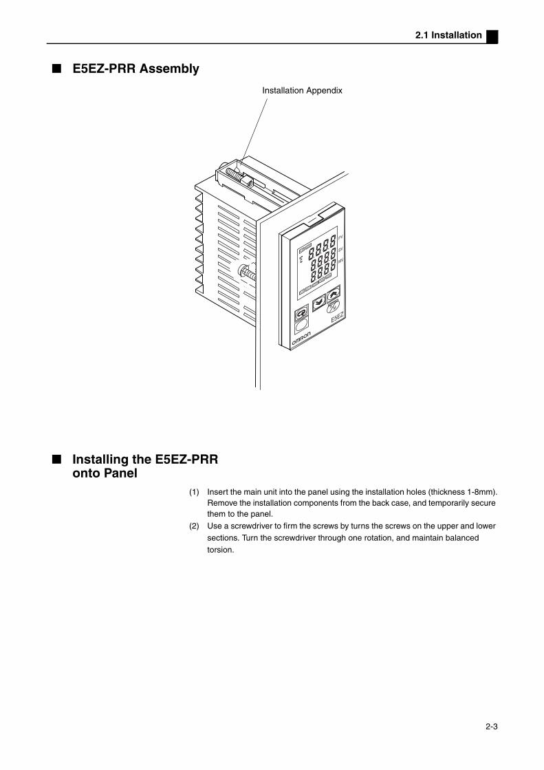
E5EZ-PRR Assembly
Installing the E5EZ-PRRonto Panel
(1) Insert the main unit into the panel using the installation holes (thickness 1-8mm).Remove the installation components from the back case, and temporarily secure them to the panel.
(2) Use a screwdriver to firm the screws by turns the screws on the upper and lower
sections. Turn the screwdriver through one rotation, and maintain balanced
torsion.
8888
8888
8888
MANU
PV
SV
MV
A M
Installation Appendix
2-3

Chapter 2 Setup
2.2 Wiring Terminals
E5EZ-PRR Wiring
Wires Connecting Notice Independent input lead and power cords are used to protect the E5EZ-PRR
and reduce the impact of external noise. Use AWG28 or larger twisted pair cable.
We recommend that when wiring the E5EZ-PRR you use solderless terminals.
Use 0.74 to 0.90N·m torque on the wiring terminals. For the M3.5 screws, use the following types of solderless terminals.
AC100~240V 50/60Hz
OPEN
WIPE
CLOSE
A
B
BV_
+
_
+
mA+
_
NOTUSE
NOTUSE
NOTUSE
Analog input type Temperatureinput type
TC Pt
EV1
EV2
1
2
3
4
5
6
7
8
9
10
11
12
13
14
12
13
14
SD
RD
SG
20
21
22
RS232C
12
13
14
B(+)
A(-)
NOT USE
RS485
AC100~240V 50/60Hz
OPEN
WIPE
CLOSE
A
B
BV_
+
_
+
mA+
_
NOTUSE
NOTUSE
NOTUSE
TC Pt
EV1
EV2
1
2
3
4
5
6
7
8
9
10
11
12
13
14
12
13
14
SD
RD
SG
20
21
22
RS232C
12
13
14
B(+)
A(-)
NOT USE
RS485
Control Output 1 (OPEN Output)
Control Output 2 (CLOSE Output)
Potentiometer
Event InputCommunication Communication
Alarm Output 1
Alarm Output 2
0.081mm2
AWG28 or larger twisted pair cable
Lead wire cross section greater than
7.2mm max
7.2mm max
2-4

2.2 Wiring Terminals
Connecting Wires Connect to terminals 1 and 2. Specifications are given below.
Power Source Power supply input/output should use standard insulation. If stronger insulation is needed, then the input and output terminals can be linked to a device whose components have no current outflow or one whose power input/output components have the highest working voltage insulation standards.
Input Connect to terminals 9 through 11 according to input type.
Control Input 1 Terminals 3 through 5 are used to control output. The following figure shows permissible outputs and their compensation circuits.
Control Input 2
Output type specifications are given below.
Alarm Output In the E5EZ-PRR alarm output 1 (ALM1) is located between terminals 21 and 22, and alarm output 2 (ALM2) is located between terminals 20 and 22.When input error output is set to “ON”, input errors will be reported via alarm output 1.
The internal compensation circuits for alarm output 1 and 2 are shown in the following figure.
Relay specifications are shown below.
Input Power Supply E5EZ-PRR
100-240VAC, 50/60Hz 10VA (10W)
11
10
11
10B
B’
9A
9Not use
11
10V
9Not use
11
10
9
Not use
mA
Thermocouple PlatinumResistance
Voltage Current
Temperature input type Analog input type
Output Types Specifications
Relay250VAC, 1A(includes initial current), electrical life: 100,000 operations, minimum load 5V10mA
3
4
5
OUT1
OUT2
Relay
Output Types Specifications
Relay250VAC, 2A (resistive load), electrical life: 100,000 operations, minimum load 1V 1mA
20
22
21ALM2
ALM1
2-5

Chapter 2 Setup
Event Input When the E5EZ-PRR2B is used with event input, terminals 12 ~ 14
should be connected.
Event input may be used in the following circumstances:
CommunicationsNon contact input polarity is shown below:
Communications(RS-232C)
When the E5EZ-PRR201 is used for communications, terminals 12 ~ 14 should be connected.
RS-232C connection 1:1 Maximum length of cable is 15m. Use a sheathed twisted pair cable (at least AWG28).
Contact input ON: Maximum 1kΩ , OFF: Minimum 100kΩ
Noncontact inputON Maximum residual voltage 1.5V, OFF: maximum current leak 0.1mA
12
13
EV1
EV2
14
12
13
EV1
EV2
14
+
+
-
12SD
RD RS-232C
SG
13
14
RS232 9P
RD(RXD)
SD(TXD)
ER(DTR)
SG
DR(DSR)
RS(RTS)
CS(CTS)
2
3
4
5
6
7
8
No.
12
13
14
SD
RD
SG
RS-232C
Communication unit wiring diagramHost
2-6

2.2 Wiring Terminals
Communications(RS-485)
When the E5EZ-PRR203 is used for communications, the communications cable should be connected between terminals 12 and 13.Specify a two terminal transmission route, including the host of the terminal node (i.e. link terminal connectors to two terminals). Maximum terminal resistance is 54Ω .
For communications, in order to meet EN61326 CLASS A transmission protection standards, add a magnetism link (TDK:ZAT1730-0730) between the K3SC and the controller.
RS-485 connection can be 1:1 or 1:N. When using 1:N connections, a maximum of 32 units can be connected, including the host. sheathed twisted pair cable (no smaller than AWG28), with the main cable 500m or less.
B(+)
A( )
RS-485
12
13
B(+)
RS-485
RS-485FG
+
-
A(-)13
12 B(+)
RS-485
A(-)13
12
A<B: “1” markA>B: “0” interval
E5EZ-PRR (No. 1) E5EZ-PRR (No. 31)
Communication unit wiring diagramHost
No. No. AbbreviationAbbreviation
Sheathed Cable
Terminal connector(120Ω, 1/2W)
No smaller than AWG28
0.081mm2
cable reference diagram
cross section of at least
2-7

Chapter 2 Setup
2.3 Installation Requirements
Ensuring Long Service LifeUse the temperature controller in the following environments:temperature:-10°C ~ +55°C (with no condensation or icing) humidity: 25%~85% (RH) When installing the temperature controller on the control panel, ensure that the temperature controller’s surroundings (not the panel’s surroundings) do not exceed 55°C.The service life of the electronic devices like the temperature controllers is determined not only by the number of times the relay is switched but also by the service life of internal electronic components. The service life of the components is influenced by the surrounding temperature: the higher the temperature, the shorter the service life, and the lower the temperature the longer the service life; therefore lowering the internal temperature will increase the service life of the temperature controller.When using or storing any model of temperature controller within the appropriate temperature and humidity ranges, when two or more temperature controllers are in close proximity either horizontally or vertically, heat radiation raises their internal temperatures, thus shortening their service lives. In such a case, use forced cooling by fans or other means of air ventilation to cool down the temperature controllers. When providing forced cooling, however, be careful not to cool down the terminal sections alone to avoid measurement errors.
DecreasingNoise
To avoid noise interference, the temperature controller’s wires on the electrical box must be kept far away from high voltage/large current power lines. Likewise wires should not be run parallel to or share the same circuit with power lines. Using independent conduits and wire guides, or sheathed wires, is also effective.Install surge absorbers or noise filters on all noise producing peripheral devices (especially electronic devices, transformers, solenoids, and other devices containing magnetic coils or inductors).If using a noise filter with the power supply, first confirm the voltage and the current, then mount the noise filter as near as possible to the temperature controller.Set up the temperature controller, along with its power supply, as far as possible from devices that generate strong, high frequency waves (high-frequency welders, high-frequency sewing machine etc.) and devices that generate surges.
Ensuring High Accuracy MeasurementWhen extending or connecting the thermocouple lead wire, be sure to use compensating wires that match the thermocouple types.When extending or connecting the lead wire of the platinum resistance thermometer, be sure to use wires that have low resistance, used for electrical impedance of three pieces of wire.When wiring the platinum resistance thermometer to the temperature controller, keep the wire route as short as possible. Separate this wiring away from the power supply wiring and load wiring to avoid inductance or other forms of noise.Mount the temperature controller so that it is horizontally level.If the measurement accuracy is low, check to see that if input float has been set correctly.
2-8

Chapter 3 Basic Operations
Chapter 3 Basic Operations
3.1 Initial Setting Samples .....................................................................3-23.2 Set Input Type..................................................................................3-4
Input Type ....................................................................................3-43.3 Selecting °C/°F ................................................................................3-6
Temperature Unit .........................................................................3-63.4 Setting Output Specifications ..........................................................3-7
Direct/reverse Operation..............................................................3-73.5 SP Setting........................................................................................3-9
SP Modifying................................................................................3-93.6 Verifying PID Constants (AT and manual settings) ........................3-10
AT (auto-tuning) .........................................................................3-10Manual Settings .........................................................................3-12
3.7 Alarm Output .................................................................................3-14Alarm Type.................................................................................3-14Alarm Value ...............................................................................3-15Alarm Delay ...............................................................................3-16
3.8 Ceramic Kiln Setting Position Proportional Control .......................3-17Application Examples ................................................................3-17Wiring.........................................................................................3-18Settings......................................................................................3-18Adjustment.................................................................................3-19Fixed settings for position proportional control ..........................3-20
3.9 During Manual Control...................................................................3-213.10 Operation Requirements................................................................3-22
3-1
Chapter 3 Basic Operations
3.1 Initial Setting Samples
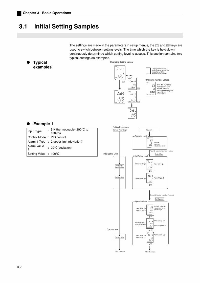
The settings are made in the parameters in setup menus, the and M keys are used to switch between setting levels. The time which the key is held down continuously determined which setting level to access. This section contains two typical settings as examples.
Typical examples
Example 1
intl
onof
in-t
0
M
M
M
in-h
100
in-l
0
intl
onof
25c
0
Changing Setting values
Changing numeric values
l.ini
l.ini
l.ini
l.ini
l.ini
0100.
Displays consecutive setting values, press the mode key until the desired value is found.
For the numeric values in each frame can be changed using the UD key.
Input Type : 5 K thermocouple -200°C to 1300°C
Control Mode : PID control
Alarm 1 Type : 2 upper limit (deviation)
Alarm Value 1 : 20°C(deviation)
Setting Value : 100°C
25c
0
M
alt1
2
in-t 5
M
al-1c
20
20
25c
100
M
M
M
r-5 run
Setting Procedures
Initial Setting Level
Operation level
Connect Power Supply
Setting Input Specifications
Set Alarm Type
Set alarm values
Start Operation Start Operation
Alarm value1=
When running
When Stopped stop
Check Alarm Type
Check Input Type 5
Operation Level
Initial Setting Level
Start Operation
Control Stop
L
l.ini
l.ini
l.ini
l.ini
run
100. .0
100. .0
Power on
Present value/set value/valve open
Press key one more than 3 second
Alarm1 Type = 5
LPress key one more than 1 second
Input Type =
Operation Level
Press DU, set value to “100˚C”
Present value/set value/valve open percentage
Ensure proper control operation
Press DU, set value to “20˚C”
3-2

3.1 Initial Setting Samples
Example 2
Input Type : 9 T thermocouple-200°C to 400°C
Control Mode : PID control
Execute AT (auto-tuning) to calculate the PID constant
Alarm1Type : 2 upper limit deviationSetting Value : 150°C
M
at
off
25c
150
25c
150
al-1c
30
r-5run
M
M
M
25
100
at
off
25
100
at
on
25c
0
in-t
9
M
alt1
2
Setting Procedures
Adjustment Level
To execute AT
During AT
During AT
After AT (auto-tuning)
PV/SPAfter AT
Once AT stops
Start Program
30
When running
During Stoppedstop
Control Stop
Start Operation
To execute AT :
Cancel AT :
l.ini
l.ini
run
ON
OFFl. adj
l. adj
l. adj
100. .0
100. .0
100. .0
100. .0
100. .0
Connect Power Supply Power on
Initial Setting Level
Input Specifications Setting
Set Alarm Type
Operation level
Set alarm values
Start operation
Operation Level Present value/set
value/valve open percentage
Present value/set value/valve open percentage
LPress key one more than 3 second
Initial Setting Level
Press DU select input type
Input Type = 9
Check Alarm Type
Alarm 1 Type = 2
LPress key one more than 1 secondOperation Level
Press DU, set value to “150˚C”
LPress key less than 1sec.
LPress key less than 1sec.
Operation Level
Present value/set value/valve open percentage
Alarm value1
Adjustment Level
Ensure the set value is “150˚C”
Ensure proper control operation
Press DU, set value to “30˚C”
3-3

Chapter 3 Basic Operations
3.2 Set Input Type
Input types include platinum resistance thermometers, thermocouples, non-contact temperature sensors, and analog input. Input type should be set based on the type of sensor being used. Product specifications include thermocouple/platinum resistance thermometers multi-input and analog input, all of which require different setting values. Please be sure to verify what type of machine you are using.
Input TypeSet input type for a “-20.0°C to 500.0°C K thermocouple”.
(1) Press the key for 3 or more seconds, and from the “operation level” access the “initial settings level”.
(2) Press the U key, input all necessary sensor set points. When using a K type
thermocouple (-20.0°C to 500.0°C), input “6” as the setting.
Note: 2 seconds after changing parameters, if the or M keys on the operation panel have not been pressed, then the settings will be fixed.
25c
0
in-t6
in-t5
l.ini
l.ini
100. 0
OperationProcedure
Operation Level
Initial Setting Level
Input Type
3-4

3.2 Set Input Type
Input type list
Initial setting value is 「5」 .
The shaded range indicates the initial settings.
Initial setting value is 「0」 .
Input Type
NameSet
PointInput Temperature Setting Range
Platinum resistance thermomet
er
Pt100
0 -200 ~ 850 (°C) /-300 ~ 1500 (°F)
1 -199.9 ~ 500.0 (°C) /-199.9 ~ 900.0 (°F)
2 0.0 ~ 100.0 (°C) /0.0 ~ 210.0 (°F)
JPt1003 -199.9 ~ 500.0 (°C) /-199.9 ~ 900.0 (°F)
4 0.0 ~ 100.0 (°C) /0. 0 ~ 210.0 (°F)
Thermocouple
K5 -200 ~ 1300 (°C) /-300 ~ 2300 (°F)
6 -20.0 ~ 500.0 (°C) /0.0 ~ 900.0 (°F)
J7 -100 ~ 850 (°C) /-100 ~ 1500 (°F)
8 -20.0 ~ 400.0 (°C) /0.0 ~ 750.0 (°F)
T9 -200 ~ 400 (°C) /-300 ~ 700 (°F)
22 -199.9 ~ 400.0 (°C) /-199.9 ~ 700.0 (°F)
E 10 0 ~ 600 (°C) /0 ~ 1100 (°F)
L 11 -100 ~ 850 (°C) /-100 ~ 1500 (°F)
U12 -200 ~ 400 (°C) /-300 ~ 700 (°F)
23 -199.9 ~ 400.0 (°C) /-199.9 ~ 700.0 (°F)
N 13 -200 ~ 1300 (°C) /-300 ~ 2300 (°F)
R 14 0 ~ 1700 (°C) /0 ~ 3000 (°F)
S 15 0 ~ 1700 (°C) /0 ~ 3000 (°F)
B 16 100 ~ 1800 (°C) /300 ~ 3200 (°F)
Non-contact
temperature sensor
ES1B
10°C ~ 70°C 17 0 ~ 90 (°C) /0 ~ 190 (°F)
60°C ~ 120°C 18 0 ~ 120 (°C) /0 ~ 240 (°F)
115°C ~ 165°C
19 0 ~ 165 (°C) /0 ~ 320 (°F)
140°C ~ 260°C
20 0 ~ 260 (°C) /0 ~ 500 (°F)
Analog Input
0 ~ 50mV 21Applicable scaling range:
-1999 ~ 9999 or-199.9 ~ 999.9.
Input Type
Specifications
Set Point
Input Temperature Setting Range
Analog Input Type
Current Input
4 ~ 20mA
0One of the following ranges applies, depending on measurements
0 ~ 20mA
1 -1999 ~ 9999
Voltage Input
1 ~ 5V 2 -199.9 ~ 999.9
0 ~ 5V 3 -19.99 ~ 99.99
0 ~ 10V 4 -1.999 ~ 9.999
3-5

Chapter 3 Basic Operations
3.3 Selecting °C/°F
Temperature Unit
Select “°C” or “°F” as the temperature unit. Under “initial level” -> “temperature unit” set the temperature unit. Initial
value is “c: Celsius”.
Select “°C”.
(1) Press the key for 3 or more seconds, and from the “operation level” access the “initial settings level”.
(2) Press the M key, select the “temperature unit” parameter.
Press the U or D key and select “c” or “f”. c: Celsius f: Fahrenheit
(3) Press the key for 1 or more seconds, to return to the “operation level”.
25c
0
d-u
c
250
in-t
5
100. 0
100. 0
l.ini
l.ini
OperationProcedure
Initial Setting Level
Operation Level
Input Type
Operation Level
Present value/set value/valve open percentage
Temperature Unit
3-6

3.4 Setting Output Specifications
3.4 Setting Output Specifications
Direct/reverse Operation
“Direct operation” indicates that MV increases as the process value increases. In contrast, “reverse operation” indicates that MV increases as the process value decreases.
For example, for the present values (PV) (temperature) used in heating control systems, is lower than the set point (SP) ( temperature ), or the present values (PV) (temperature) the cooling control system present values (PV) is higher than the set point (SP), MV increases in proportion to the difference between PV and SP.The processes described above refer to “reverse operation” for heating control systems and “direct operation” for cooling control systems.
Direct/reverse operation can be set under the “direct/reverse operation” parameter (initial settings level). The “direct/reverse operation” parameter's initial setting is “reverse operation”.
Operation Value Operation Value
Low Temperature
HighTemperature
Direct OperationSet Point
Low Temperature
HighTemperature
Reverse OperationSet Point
3-7

Chapter 3 Basic Operations
In this example, the “input type”, “temperature unit”, “direct/reverse operation” parameters are monitored.
“input type ” = “5” K type thermocouple
“temperature unit” = “c” Celsius“direct/reverse operation” = “or-r” reverse operation
(1) Press the key for 3 or more seconds, and from the “operation level” access the “initial settings level”.
(2) Display input type. The first time you adjust this setting, the input type is “5” K
type thermocouple. Press the U or D key, select different sensor.
(3) Press the M key, select the “temperature unit” parameter. Initial value is “c”:
Celsius. Press the U or D key select “f”: Fahrenheit.
(4) Press the M key and select the “direct/reverse operation” parameter. The initial
setting is “or-r” reverse operation. Press the U or D key to change.
(5) Press the key for 1 or more seconds to return to the “operation level”.
25c
0
d-uc
in-t5
25c
0
orenor-r
100.0
100.0
l.ini
l.ini
l.ini
25c
0
d-uc
in-t
5
25c
0
oren
or-r
100.0
100.0
l.ini
l.ini
l.ini
OperationProcedure
Initial Setting Level
Operation Level
Input Type
Temperature Unit
Present value/set value/valve open percentage
Operation Level
Direct/Reverse Operation
3-8

3.5 SP Setting
3.5 SP Setting
When the power supply is connected, the “operation level” will be displayed. (No. 1 display) is the process value, (No. 2 display) is the set point , (No. 3 display) is the valve open percentage.
SP Modifying When the “operation/adjustment protection” parameter is set to “3”, the set point cannot be changed. For details please see “4.8 Using the Key Protection Level”.
“Present value/ set point” parameter (operation level). Press the U and D keys, modify the set point, and set all necessary set points. Within 2 seconds of setting the new value, the new set point will be fixed.
Multiple set point (SP1 to SP4) are possible (Refer to page 5-14).
In this example, the set point changes from “0°C” to “200°C”.
(1) Normally, the “present value/ set point” parameter is displayed. The set point is “0°C”.
(2) Use the UD key, to change the set point to “200°C”.
25c
0
0100.
Operation Level
25c
0
0100.
25c
200
0100.
OperationProcedure
Operation Level
3-9

Chapter 3 Basic Operations
3.6 Verifying PID Constants (AT and manual settings)
AT (auto-tuning) When using auto-tuning, the program will force modifications in operation volume to calculate the set point's optimal PID parameter, and calculate the unique automatic settings of the controlled object (the “limit cycle method”).
Select “on: Execute AT” execute AT (auto-tuning), select “off: Cancel AT” to cancel AT (auto-tuning). When AT is finished, “on” will fall-back to “off” automatically.
In the “adjustment level”, the “proportional band (P)”, “integral time (I)”, and “derivative time (D)” parameters indicate the AT (auto-tuning) results.
Explanation When the “execute/cancel AT” parameter is set to “ON”, AT (auto-tuning) is activated. During AT execution, the “execute/cancel AT” parameter flashes on the No. 1 display. When AT is finished, the “execute/cancel AT” parameter goes off, and No. 1 display stops flashing.
If while AT is executing you switch to the “operation level ”, No. 2 display will flash to indicate that AT is executing.
When AT is executing, only the “communication writing”, “run/stop” and “execute/cancel AT” parameters may be changed. Other parameters may not be changed.
i
233
d
40
pc
8.0
l. adj
l. adj
l. adj
Adjustment Level
Proportional Band
Integral Time
Derivative Time
at
off
l.adj
at
on
l.adj
Execute/cancel AT
When AT is executing
No. 1 Display
25c
100
25c
100
100.0 100.0
No. 2 Display
When AT is executing
present value/ set point /valve open percentage
3-10

3.6 Verifying PID Constants (AT and manual settings)
Using auto-tuning (AT).
(1) Press the key for less than 1 second to switch from the “operation level” to the “adjustment level”.
(2) Press the U key to execute AT (auto-tuning).
When AT is executing, “on” will be displayed.
(3) When AT finishes, “off” will be displayed again.
(4) Press the key to return to “operation level”.
at
off
l.adj
at
on
at
off
25c
0
0
l.adj
l.adj
100.
OperationProcedure
Present value/set value/valve open percentage
Operation Level
Adjustment level
Execute/cancel AT
3-11
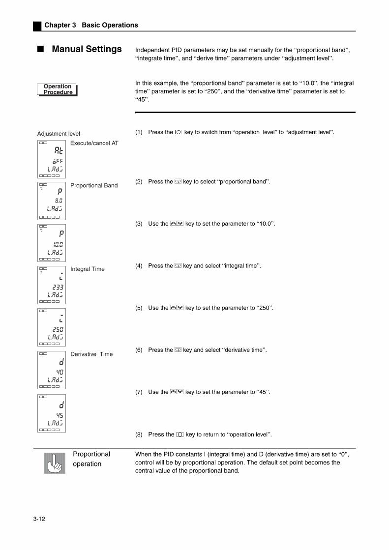
Chapter 3 Basic Operations
Manual Settings Independent PID parameters may be set manually for the “proportional band”, “integrate time”, and “derive time” parameters under “adjustment level”.
In this example, the “proportional band” parameter is set to “10.0”, the “integral time” parameter is set to “250”, and the “derivative time” parameter is set to “45”.
(1) Press the key to switch from “operation level” to “adjustment level”.
(2) Press the M key to select “proportional band”.
(3) Use the UD key to set the parameter to “10.0”.
(4) Press the M key and select “integral time”.
(5) Use the UD key to set the parameter to “250”.
(6) Press the M key and select “derivative time”.
(7) Use the UD key to set the parameter to “45”.
(8) Press the key to return to “operation level”.
Proportional operation
When the PID constants I (integral time) and D (derivative time) are set to “0”, control will be by proportional operation. The default set point becomes the central value of the proportional band.
OperationProcedure
at
off
p
ic
233
i
250
d
40
d
45
p
c
c
l.adj
l.adj
l.adj
l.adj
l.adj
l.adj
l.adj
10.0
Execute/cancel AT
Adjustment level
Proportional Band
Integral Time
Derivative Time
3-12

3.6 Verifying PID Constants (AT and manual settings)
When tuning P (proportional band)
When tuning I (integral time)
When tuning D (derivative time)
When P is increasing
The curve gradually increases, then enters a long period of stability to prevent overshoot.
When P is decreasing
When overshoot or vibration occurs after the curve stabilizes, the set point will be reached very quickly.
When I is increasing
The present value needs a long time to reach the set point. Overshoot/undershoot or vibration still occurs after stabilization.
When I is decreasing
When overshoot/undershoot or vibration occurs, and the curve is still increasing rapidly.
When D is increasing
When overshoot/undershoot and stable time decreases, but the curve itself experiences slight vibration.
When D is decreasing
Overshoot /undershoot increases, it takes a long time for present values to reach its set point.
Set Point
Set Point
Set Point
Set Point
Set Point
Set Point
3-13

Chapter 3 Basic Operations
3.7 Alarm Output
Alarm output is determined by “alarm type” and “alarm hysteresis”. The “alarm type”, “alarm value”, “upper limit alarm” and “lower limit alarm”
parameters are explained below.
Alarm Type
0
1 *2
2
3
4 *3
5 *4
6
7
8
9
10
11
ONOFF
L H
SP
X
X
ONOFF
SP
XONOFF
SP
SP
ONOFF
XONOFF
SP
SP
ONOFF
XONOFF
SP
XONOFF
SP
XONOFF
SP
ONOFF
L H
SP
ONOFF
L H
SP*5
XONOFF
0
XONOFF
0
XONOFF
0
XONOFF
0
XONOFF
0
XONOFF
0
XONOFF
0
XONOFF
0
X
*1
*1
*1
When alarm value X is positive When alarm value X is negativeSet Value Type
standby sequence upper and lower limits
standby sequence upper limit
standby sequence lower limit
absolute value upper limit
absolute value lower limit
standby sequence absolute value upper limit
standby sequence absolute value lower limit
upper and lower limit range
No alarm function
upper and lower limits
upper limit
lower limit
Output OFF
Alarm Output Operation
*1:
*2: setting value: 1 upper and lower limit alarms
*3
*4:*The upper and lower limit alarms described above-
*5:
case 1
Each alarm point my be set independently with “L” and “H” representing the upper and lower limit values, and set points 1, 4, and 5.
case 2
case 2
case 3 (Always ON)
setting value: 4case 1
Upper and lower limit range alarm
case 3 (Always OFF)
setting value : 5 standby sequence upper and lower limit alarms
setting value: 5 standby sequence upper and lower limit alarms
In cases 1 and 2, if there is significant overlap between the upper and lower limit values after hysteresis, the alarm will always be OFF.Examples of case 1 and 2 : In case 3, the alarm is always OFF.
If there is significant overlap between the upper and lower limit values after hysteresis, the alarm will always be OFF.Alarm types include “alarm1 ~ 2” (initial settings level ), and each should be set individually. Initial value is “2: Upper limit”.
3-14
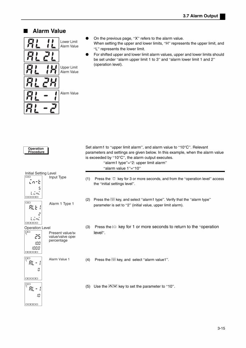
3.7 Alarm Output
Alarm Value On the previous page, “X” refers to the alarm value.
When setting the upper and lower limits, “H” represents the upper limit, and “L” represents the lower limit.
For shifted upper and lower limit alarm values, upper and lower limits should be set under “alarm upper limit 1 to 3” and “alarm lower limit 1 and 2” (operation level).
Set alarm1 to “upper limit alarm”, and alarm value to “10°C”. Relevant parameters and settings are given below. In this example, when the alarm value is exceeded by “10°C”, the alarm output executes.
“alarm1 type”=“2: upper limit alarm” “alarm value 1”=“10”
(1) Press the key for 3 or more seconds, and from the “operation level” access the “initial settings level”.
(2) Press the M key, and select “alarm1 type”. Verify that the “alarm type”
parameter is set to “2” (initial value, upper limit alarm).
(3) Press the key for 1 or more seconds to return to the “operation level”.
(4) Press the M key, and select “alarm value1”.
(5) Use the UD key to set the parameter to “10”.
Lower Limit Alarm Value
Upper Limit Alarm Value
Alarm Value
in-t
5
l.ini
alt1
2
25
100
c
al-1
0
c
al-1
10
c
l.ini
100.0
OperationProcedure
Initial Setting LevelInput Type
Operation LevelPresent value/sevalue/valve openpercentage
Alarm Value 1
Alarm 1 Type 1
3-15
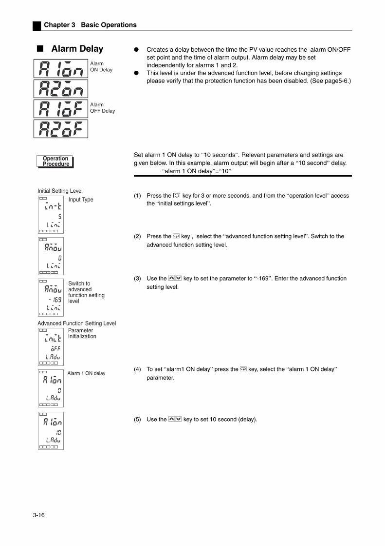
Chapter 3 Basic Operations
Alarm Delay Creates a delay between the time the PV value reaches the alarm ON/OFF set point and the time of alarm output. Alarm delay may be set independently for alarms 1 and 2.
This level is under the advanced function level, before changing settings please verify that the protection function has been disabled. (See page5-6.)
Set alarm 1 ON delay to “10 seconds”. Relevant parameters and settings are given below. In this example, alarm output will begin after a “10 second” delay.
“alarm 1 ON delay”=“10”
(1) Press the key for 3 or more seconds, and from the “operation level” access the “initial settings level”.
(2) Press the M key , select the “advanced function setting level”. Switch to the
advanced function setting level.
(3) Use the UD key to set the parameter to “-169”. Enter the advanced function
setting level.
(4) To set “alarm1 ON delay” press the M key, select the “alarm 1 ON delay”
parameter.
(5) Use the UD key to set 10 second (delay).
Alarm ON Delay
Alarm OFF Delay
in-t
5
inil.
0
init
off
a1on
0
a1on
10
inil.
inil.
OperationProcedure
Initial Setting Level
Input Type
Switch toadvanced function setting level
Advanced Function Setting Level Parameter Initialization
Alarm 1 ON delay
3-16

3.8 Ceramic Kiln Setting Position Proportional Control
3.8 Ceramic Kiln Setting Position Proportional Control
Using potentiometer to read the degree of valve opening, along with Open and CLOSE tuning control is called position proportional control or ON/OFF servo control.
Application Examples
When using position proportional to control valves in combustion devices, position proportional control should be used. See the following figure for measurement devices.
SP
PV
MV
PID
OUT1 OUT2
Temperature InputAnalog Signal Input Potentiometer
SP Ramp
SP
RUN
888888888888
MANU
PV
SV
MV
AM
E5EZ-PRR
Set Value
SP ramp as time unit
SP ramp setting value
Time
Temperature Sensor
Combustion Device
The SP ramp function allows limits to be placed on temperature changes which control the temperature within a specific range. This is useful for ceramic kilns, in which severe temperature changes may cause damage or corruption.
Ramp
NOTES
F/B
open/close
3-17

Chapter 3 Basic Operations
WiringInput should be connected to terminals 9, 10, and 11 depending on input type. The OUT1 terminal links to the position proportional valve OPEN side and the OUT2 terminal to the CLOSE side.
SettingsUse position proportional control type position proportional valves, with travel time (from fully closed to fully open) at 45 seconds to floating control. And use the SP ramp function at 10.0°C/minute to gradually change the present value.Related setting data and information are given below:
Travel time and SP ramp set point are set, other parameters use the initial values.
(1) Press the key for 3 or more seconds, and from the “operation level” access the “initial settings level”.
CLOSE
OPEN
C W O
ceramic kiln (combustion)
SensorVALVE
Position Proportional Valve
Combustion device
「Direct Reverse Operation」
= 「or-r: Reverse Operation」 (initial value)
「Closed/floating」 = 「flot: Floating」 (initial value)
「Travel time」 =“45” second
「SP ramp Set Point」 = “10”
in-t
5
l.ini
3-18

3.8 Ceramic Kiln Setting Position Proportional Control
(2) Press the M key repeatedly, select “mot: Travel time”. Press the U key, set
the set point to “45”.
(3) Press the key for 1 second or more to return to the “operation level”. When
“present value/target value/valve open percentage” is displayed, press the U
key to set the target value to “250”.
(4) Press the key for less than 1 second to switch from the “operation level” →
“adjustment level”.
(5) Press the M key repeatedly, select “sprt: SP ramp set point”, then press the
U key to set the value to “10”.
Adjustment For PID adjustment please execute AT. For detailsplease see "3.6 Verifying PID Constants (AT and manual settings)" page 3-10.
mot
30
l.ini
45
1 0
sprt
0
l.adj
U
U
U
25
100.00 25 0
at
l.adj
off
Travel Time
Operation LevelProcess value/set point /valve open percentage
Adjustment Level
SP is ramp set point
3-19

Chapter 3 Basic Operations
Fixed settings for position proportional control
After selecting position proportional control, “closed/floating”, “electro-mechanical calibration”, “Travel time”, “position proportional dead band”, “switch hysteresis”, “potentiometer input error”, “present value dead band” may be used.
Closed/floating Closed controllink potentiometer for valve open percentage feedback control.
Floating controlPotentiometer non-feedback valve open percentage control can be done without linkage to the potentiometer. For settings see page 5-26.
Calibration and travel time
Calibration is similar to closed control or monitor valve opening control when connected to a potentiometer. The “travel time” from valve completely open to valve completely closed is also set to self measuring.
Floating control with no potentiometer connected also requires manual setting of “travel time”. The time from valve completely closed to valve completely open is set as “travel time”. For settings see page 5-27.
Position Proportional Dead Band
The valve output period (the time it takes OPEN output and CLOSE output to switch from ON to OFF) is set as the “position proportional dead band”, and hysteresis is set as “switch hysteresis”.
Switch position proportional hysteresis
The relationship to the valve opening is given below:
For settings see page 5-18.
PV dead band When the present value is in the present value dead band, then for control purposes present value = set point; this function presents unnecessary output when the present value approaches the set point. For settings see page 5-39.
Potentiometer input errors
When the potentiometer produces errors under closed control, select control stop or switch to floating control to continue with control.
-100%
OFF
ON
0 100%
Switch position proportional hysteresis
Dead band
MV- valve opening
3-20
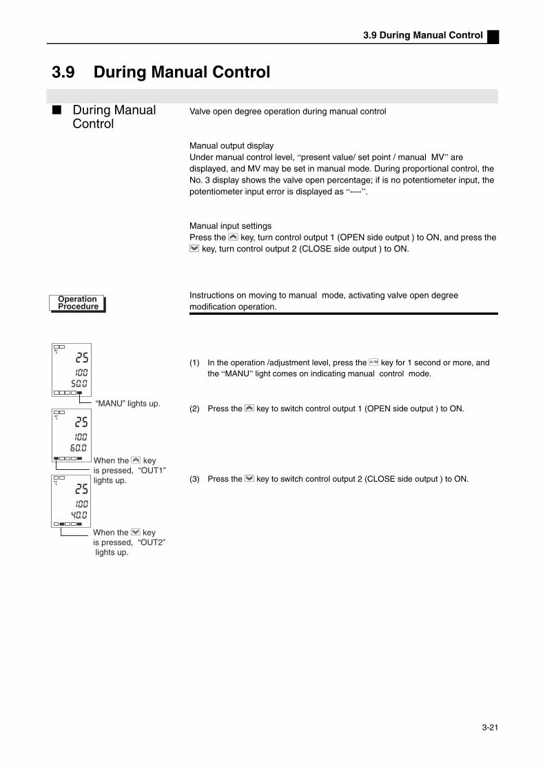
3.9 During Manual Control
3.9 During Manual Control
During Manual Control
Valve open degree operation during manual control
Manual output displayUnder manual control level, “present value/ set point / manual MV” are displayed, and MV may be set in manual mode. During proportional control, the No. 3 display shows the valve open percentage; if is no potentiometer input, the potentiometer input error is displayed as “----”.
Manual input settingsPress the U key, turn control output 1 (OPEN side output ) to ON, and press the D key, turn control output 2 (CLOSE side output ) to ON.
Instructions on moving to manual mode, activating valve open degree modification operation.
(1) In the operation /adjustment level, press the A key for 1 second or more, and the “MANU” light comes on indicating manual control mode.
(2) Press the U key to switch control output 1 (OPEN side output ) to ON.
(3) Press the D key to switch control output 2 (CLOSE side output ) to ON.
25
100
c
c
25
100
c
40.0
50.0
25
100
60.0
OperationProcedure
“MANU” lights up.
When the U key is pressed, “OUT1”lights up.
When the D key is pressed, “OUT2” lights up.
3-21

Chapter 3 Basic Operations
3.10 Operation Requirements
(1) Output commences roughly 4 seconds after power is turned on; please take this into consideration when selecting a control circuit.
(2) Please ensure that at least 30 minutes are provided for pre-heating.
(3) When using self-tuning, turn on the temperature controller at the same time as the load (e.g heater), or connect the load before the temperature controller is
turned on. If the temperature controller's power supply is turned on before the
load is connected, then self tuning may not be accurate and control may not be optimal.
When pre-heating is complete and operation has begun, the power supply should be disconnected immediately after pre-heating is complete, then the temperature controller and load should be turned on simultaneously (the temperature control's power supply may also be turned on and off by switching from stop mode to run mode.)
(4) If the Temperature Controller is used close to radios, television sets or wireless
devices, it may affect reception.
3-22

Chapter 4 Applied Operations
Chapter 4 Applied Operations
4.1 Input Shift Values.............................................................................4-2Input Shift.....................................................................................4-2Calculating Input Shift Values (2 Point Shift) ...............................4-31 Point Shift Method.....................................................................4-42 Point Shift Method.....................................................................4-42 Point Temperature Input Shift Example ....................................4-5
4.2 Alarm Hysteresis .............................................................................4-6Standby Sequence ......................................................................4-6Alarm Latch .................................................................................4-6Shutdown on Alarm /Alarm Activation .........................................4-7Alarm Operation Overview...........................................................4-7Alarm Delay Function ..................................................................4-8
4.3 Calibrating Upper and Lower Limits (Analog Signal Input) ..............4-9Analog Signal Input......................................................................4-9
4.4 Using Event Input ..........................................................................4-11Setting Event Input ....................................................................4-11Using Multiple Set Points ...........................................................4-11Key Operation Settings ..............................................................4-12Setting........................................................................................4-12Using Run/Stop Control .............................................................4-14
4.5 Setting SP Upper and Lower Limit Values.....................................4-15Set Point Limits ..........................................................................4-15Settings......................................................................................4-16
4.6 Using the SP Ramp Function (to limit rate of SP change).............4-17SP Ramp ...................................................................................4-17
4.7 Switching to the Advanced Function Level ....................................4-194.8 Using The Key Protection Level.....................................................4-20
Key Protection............................................................................4-20
4-1

Chapter 4 Applied Operations
4.1 Input Shift Values
Input Shift Displays the input shift type that accords with the sensor selected under the present “input type” parameter.
1 point shift 2 point shift is only used with non-contact type temperature sensors. When selecting 1 point shift, set the “temperature input shift” parameter set
point to the entire temperature input range. For example, if the set point is 200°C, if the input shift value is set to “1.2°C”, then the set point will be considered 201.2°C.
In this example, 1 point input shift is used to set the K type thermocouple input value shift to “1°C”
(1) Press the key, switch from “operation level” to “adjustment level”.
(2) Press the M key, select “temperature input shift”.
(3) Use the UD key to set it to “1.0”.
(4) Press the key, return to “operation level”. The set point is now 1°C higher than it was before.
i n 5Temperature
Upper Limit Value After Shift
Lower Limit Value Input Shift Value
Before Shift
Parameters
30
200
c
at
off
31
200
c
ins
1 0
c
.
ins
0 0
c
.
100.0
100.0
l.adj
l.adj
l.adj
OperationProcedure
Operation level
Adjustment Level
Temperature Input Shift
Operation Level
PV/SP/valve open percentage
4-2

4.1 Input Shift Values
2 point shift By independently setting the sensor’s upper limit input shift values and lower limit input shift values, you can shift the input temperature range on a non-contact temperature sensor. In other words, by setting different shift values for the two ends of the temperature range, all the values in the range will be shifted. For example, if the upper limit value is “2°C”, and the lower limit value is “1°C”, then the entire sensor range will have an average shift value of 1.5°C at 50% input.
Under “upper limit temperature input shift values” set the upper limit value, and under “lower limit temperature input shift values” set the lower limit value.
Calculating Input Shift Values (2 Point Shift)When a non-contact temperature sensor model No. ES1B is connected to the temperature controller model E5EZ-PRR,seeral degrees to several tenth of degrees shift will occur. Therefore a 1 point or 2 point shift compensation must be used for the read out value.When the detection controller error sensor bias current reaches the output impedance of the non-contact temperature sensor, a shift will occur. The point shift will only occur with a non-contact temperature sensor, and may not be used with other input types.[Set Up] (1) Set the controller’s temperature range based on the non-contact
temperature sensor’s input specifications.
(2) As shown in figure 1, use a temperature gauge capable of measuring the temperature of the controlled object, in order to execute 1 point shift and 2 point
shift.
Temperature
Upper Limit Value
Lower Limit Value
After Shift
Before Shift
Upper Limit Temperature Input Shift
InputLower Limit Temperature Input Shift
UNAM
A M
Non-contact TemperatureSensor
(C) Controlled Object
(B) Temperature Gauge
(A) E5EZ-PRR Temperature Controller
Figure 1 Compensating for a non-contact temperature sensor
4-3

Chapter 4 Applied Operations
1 Point Shift Method
(1) In figure 1, select a set point near the controlled temperature value of the controlled object. Assume that temperature (C) and temperature (B) of the controlled object are the same.
(2) Check the controlled object’s temperature (B) and the controller's reading (A). Input
shift values may be calculated as shown below, with “insl” and “insh” set to the
same value.
figure 2 shows result of a 1 point temperature input shift
(3) After setting input shift values, check the controlled object's temperature (B) and the controller reading (A), if they are roughly equal, then the temperature input
shift has been successful.
2 Point Shift Method
To increase the accuracy of the reading values across the sensor range, the 2 point input shift method may be used.(1) To shift two points of the controller’s reading, use two points near room
temperature and the controlled temperature of the controlled object. Therefore, set the controlled object’s temperature settings near room temperature and the set point, then check the controlled object’s temperature (B) and controller reading (A).
(2) Use the reading and temperature shift values from step 1, as well as equations (1) and (2), to calculate the upper and lower limit temperature input shift values.figure 3 shows the results of the 2 point temperature input shift.
insl
10
c
insh
10
c
l. .adj
l. .adj
Adjustment level
Upper Limit Temperature Input Shift
Lower Limit Temperature Input Shift
controlled object’s temperature (B) - controller reading (A)
Controller Reading (A)Temperature Reading After Shift (120°C)Temperature Reading Before (110°C)
After Shift
Before Shift
Input Shift Value (10°C)
Controlled Object Temperature Reading (B)
Approaching Set Point (120°C)
figure 2 1 Point Temperature Input Shift
Controller reading (A)
g p pp
X1 room temperature (such as 25°C)
Setting temperature upper limit YH such as 260°C)
Temperature reading X2 after input shift (110°C)
Temperature reading Y2 before input shift (105°C
Temperature reading Y1 before input shift (40°C)Temperature reading X1 after input shift (25°C)
Lower limit temperature input shift X2 vicinity of set point(such as 110°C)Setting temperature
lower limit YL (such as 0°C)
After shift
Upper limit temperature input shift
Before shift
figure 3 2 Point Temperature Input Shift
Controlled object temperature reading (B)
4-4

4.1 Input Shift Values
Use the following method to calculate the lower limit temperature input shift values.
Use the following method to calculate the upper limit temperature input shift values.
(3) After setting insl and insh as the calculated value, check the controller
reading (A) and controlled object's temperature (B).
(4) When shifting input near room temperature (environmental temperature) and set
point 2 point, you must select two points near the ends of the sensor's
measurement range, to increase the overall accuracy across the sensor’s measurement range.
2 Point Temperature Input Shift Example
This example uses ES1B non-contact temperature sensor, temperature range
0°C ~ 260°C YL and YH in equations 1 and 2 are set as follows:lower limit temperature YL set to 0°C; upper limit temperature YH set to 260°C. Check the controlled object’s temperature.When room temperature X1 is 25°C, the controller reading Y1 is 40°C, the temperature near the set point X2 is 110°C, and the controller reading Y2 is 105°C,
lower limit temperature input shift values
upper limit temperature input shift values
insl= ( ) ( ) ( )111122121
YXYXYXYYYYL
−+−−−×−
−Eq 1
insh = ( ) ( ) ( )111122121
YXYXYXYYYYH
−+−−−×−
−Eq 2
insh
53
c
insl
-27
l.adj
l.adj
c
Adjustment level
Lower Limit Temperature Input Shift
Upper Limit Temperature Input Shift
insl= ( ) ( ) ( ) 3 (˚C).274025402510511040105
400−=−+−−−×
−
−
insh= ( ) ( ) ( ) 7 (˚C).52402540251051104010540260
=−+−−−×−
−
4-5

Chapter 4 Applied Operations
4.2 Alarm Hysteresis
When the alarm is used, alarm output hysteresis may be set according to the figure below:
Under the “alarm hysteresis 1 to 2” parameters (advanced function level ), you can independently set the alarm hysteresis. The initial value is “0.2°C or °F”. (analog input initial value is “0.02%FS”)
Standby Sequence
When the first alarm is triggered, the “standby sequence” can temporarily inactivate the alarm output. Alarm output will continue to be effective during subsequent alarm events.
For example, during standard heating applications if the standard “low level” alarm is used, then when the controller is turned on the alarm function will be effective. But if using the “standby sequence”, then the first time the heating alarm output will not be effective, rather the temperature must exceed the alarm set point before the alarm is activated. When the temperature is lower than the alarm set point, the alarm output is effective.
Standby Sequence Restart
After alarm output, the standby sequence is cancelled. But by resetting the “standby sequence” parameter (advanced function level ) you can reactivate the standby sequence.For details, please see the “standby sequence” parameter in “Chapter Five, Parameters” .
Alarm Latch The “alarm latch” function sets the alarm output as the permanent connection status, regardless of temperature variations.
The alarm latch may be cancelled when disconnecting the power. (Note: when switching to initial level, communication level or advanced function level, alarm latch will be cancelled.)
Upper Limit Alarm
Alarm Hysteresis
Alarm Value Alarm Value
Alarm Hysteres
Lower Limit Alarm
4-6
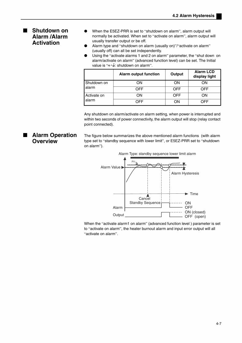
4.2 Alarm Hysteresis
Shutdown on Alarm /Alarm Activation
When the E5EZ-PRR is set to “shutdown on alarm”, alarm output will normally be activated. When set to “activate on alarm”, alarm output will usually transfer output or be off.
Alarm type and “shutdown on alarm (usually on)”/“activate on alarm” (usually off) can all be set independently.
Using the “activate alarms 1 and 2 on alarm” parameter, the “shut down on alarm/activate on alarm” (advanced function level) can be set. The Initial value is “n-o: shutdown on alarm”.
Any shutdown on alarm/activate on alarm setting, when power is interrupted and within two seconds of power connectivity, the alarm output will stop (relay contact point connected).
Alarm Operation Overview
The figure below summarizes the above mentioned alarm functions (with alarm type set to “standby sequence with lower limit”, or E5EZ-PRR set to “shutdown on alarm”).
When the “activate alarm1 on alarm” (advanced function level ) parameter is set to “activate on alarm”, the heater burnout alarm and input error output will all “activate on alarm”.
Alarm output function OutputAlarm LCD
display light
Shutdown on alarm
ON ON ON
OFF OFF OFF
Activate on alarm
ON OFF ON
OFF ON OFF
ONOFFON (closed)OFF (open)
Alarm Type: standby sequence lower limit alarm
Alarm Value
Alarm Hysteresis
TimeCancel
Standby SequenceAlarm
Output
4-7
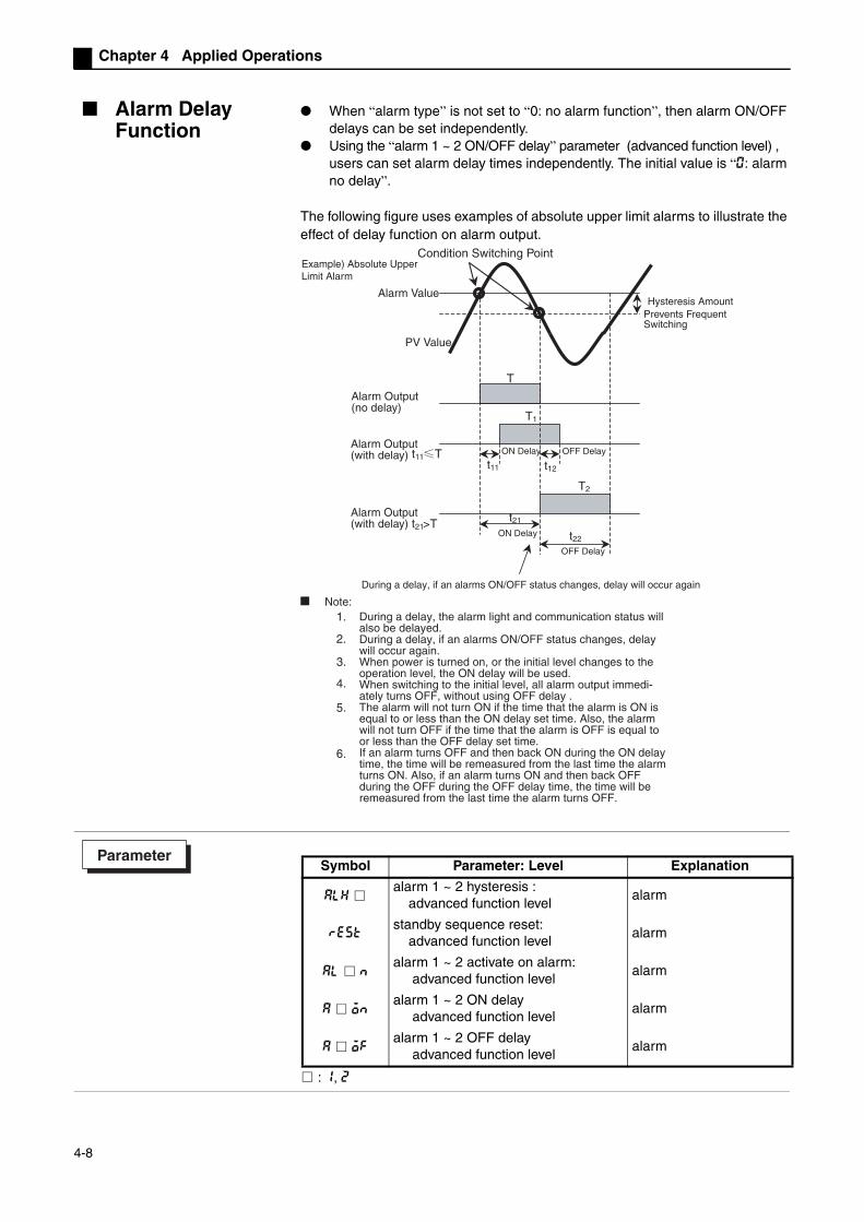
Chapter 4 Applied Operations
Alarm Delay Function
When “alarm type” is not set to “0: no alarm function”, then alarm ON/OFF delays can be set independently.
Using the “alarm 1 ~ 2 ON/OFF delay” parameter (advanced function level) , users can set alarm delay times independently. The initial value is “0: alarm no delay”.
The following figure uses examples of absolute upper limit alarms to illustrate the effect of delay function on alarm output.
: 1, 2
1.
2.
3.
4.
5.
6.
t11 T
ON Delay
OFF Delay
T
T1
t11
T2
t21
t22
t21>T
ON Delay OFF Delay
t12
Example) Absolute Upper Limit Alarm
Hysteresis AmountPrevents Frequent Switching
PV Value
Alarm Value
Alarm Output (no delay)
Alarm Output (with delay)
Alarm Output (with delay)
Condition Switching Point
During a delay, if an alarms ON/OFF status changes, delay will occur again
Note:During a delay, the alarm light and communication status will also be delayed.During a delay, if an alarms ON/OFF status changes, delay will occur again.When power is turned on, or the initial level changes to the operation level, the ON delay will be used. When switching to the initial level, all alarm output immedi-ately turns OFF, without using OFF delay .The alarm will not turn ON if the time that the alarm is ON is equal to or less than the ON delay set time. Also, the alarm will not turn OFF if the time that the alarm is OFF is equal to or less than the OFF delay set time.If an alarm turns OFF and then back ON during the ON delay time, the time will be remeasured from the last time the alarm turns ON. Also, if an alarm turns ON and then back OFF during the OFF during the OFF delay time, the time will be remeasured from the last time the alarm turns OFF.
Symbol Parameter: Level Explanation
alhalarm 1 ~ 2 hysteresis : advanced function level
alarm
reststandby sequence reset: advanced function level
alarm
al nalarm 1 ~ 2 activate on alarm: advanced function level
alarm
a onalarm 1 ~ 2 ON delay advanced function level
alarm
a ofalarm 1 ~ 2 OFF delay advanced function level
alarm
Parameter
4-8
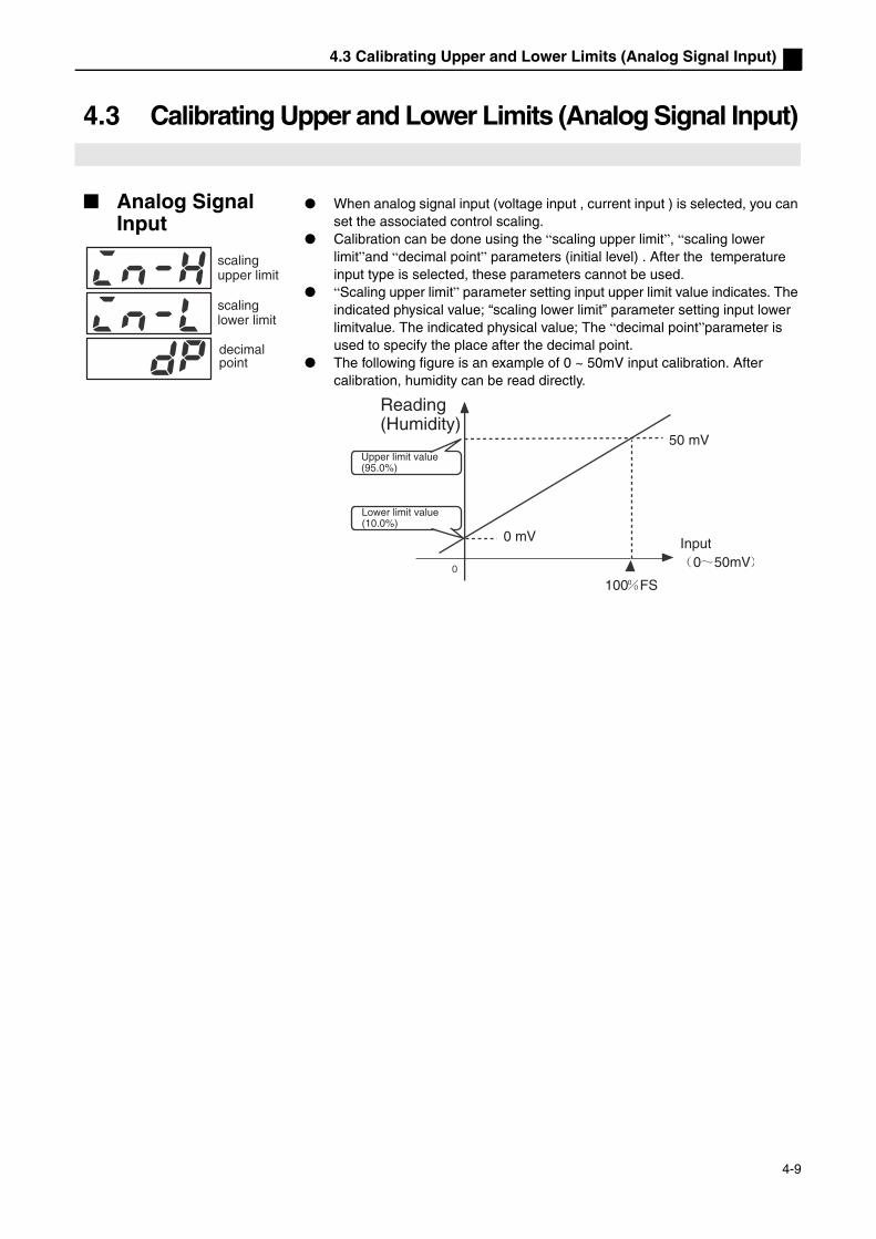
4.3 Calibrating Upper and Lower Limits (Analog Signal Input)
4.3 Calibrating Upper and Lower Limits (Analog Signal Input)
Analog Signal Input
When analog signal input (voltage input , current input ) is selected, you can set the associated control scaling.
Calibration can be done using the “scaling upper limit”, “scaling lower limit”and “decimal point” parameters (initial level) . After the temperature input type is selected, these parameters cannot be used.
“Scaling upper limit” parameter setting input upper limit value indicates. The indicated physical value; “scaling lower limit” parameter setting input lower limitvalue. The indicated physical value; The “decimal point”parameter is used to specify the place after the decimal point.
The following figure is an example of 0 ~ 50mV input calibration. After calibration, humidity can be read directly.
scaling upper limit
scaling lower limit
decimal point
0 50mV
100 FS
0 mV
50 mV
Reading (Humidity)
Upper limit value(95.0%)
Lower limit value(10.0%)
Input
4-9

Chapter 4 Applied Operations
In this example, calibrating the lower limit value changed the 0 ~ 50mV input value to 10.0% through 95.0%.
(1) Press the key for 3 or more seconds, to switch from “operation level” to“initial level”.
(2) Use the M key to select “scaling upper limit”.
(3) Use the UD key to set the parameter to “950”.
(4) Press the M key, to select “scaling lower limit”.
(5) Use the UD key to set the parameter to “100”.
(6) Use the M key to select the position of the decimal point.
(7) Use the UD key to set the parameter to “1”.
(8) Press the key for 1 or more seconds to return to the “operation level”.
in-t
21
in-l
0
in-l
100
in-h
100
in-h
950
dp
0
dp
1
l.ini
l.ini
l.ini
l.ini
l.ini
l.ini
l.ini
OperationProcedure
Initial Setting Level
Input Type
Scaling Upper Limit
Scaling Lower Limit
Decimal Point
4-10

4.4 Using Event Input
4.4 Using Event Input
Setting Event Input
Run/stop control and Auto/Manual selection can be done with event input assignment 1 and 2.The following table shows “number of multi set points used ”, it gives event input 1 and 2 function assignment.When 2 or 4 multiple set points are used, use the “number of multi-set points used” parameter, which determines whether or not “event input assignment 1” and “event input assignment 2” are displayed.
*1 Only when using event input indicators 1 or 2 , the “stop (run/stop) switching” and Auto/Manual can be set.Once “STOP” is assigned to one event input, the other side is set to “NONE” or “MANU”.
When setting two external input set points, the “number of multi-SP used” parameter may be set to: select set point (0/1)
When “number of multi-SP used” is set to “1” (initial value) , two set points may be selected. This setting may not be changed. Set point 0 or 1 is indicated by the event input 1 status.
Using Multiple Set Points “Multiple set points” is a presetting set points 0 through 3 function . It uses both
input event 1 and 2 to select set points.
Using Event Input With Multiple
When using E5EZ-PRR2B , and the “number of multi-SP used” is set to “1” or “2”, multiple set points can be used. when “multi-SP used” is set to “1”
When “multi-SP used” is set to “2”
*Event input the E5EZ-PRR2B model. Event input ON/OFF should be used when the power is on. It can distinguish 50ms or more of input ON/OFF.
No. of Multi-SP
Used
Setting Event Input FunctionEvent Input
Assignment 1Event Input
Assignment 2Event Input 1
FunctionEvent Input 2
Function
0 NONE or STOP or MANU “1” none or Switching RUN/STOP or Switching Auto/Manual “1”
1- (Not
displayed)NONE or STOP
or MANU
2 set points multi set points (alternate set
point 0/1)
No or Switching RUN/STOP or
Switching Auto/Manual
2 - (not displayed)4 set points multi set point(alternate set point 0/1/2/3)
Event Input 1 Select Set Point
OFF set point 0
ON set point 1
Event Input 1 Event Input 2 Select Set Point
OFF OFF set point 0
ON OFF set point 1
OFF ON set point 2
ON ON set point 3
4-11

Chapter 4 Applied Operations
Key Operation Settings
Using “multi-SP” set point modification, “target value 0 ~ 3” can be changed . “Multi-SP” display conditions are as follows: For products without event input specifications, “use multi SP ” is “ON”. For products with event input specifications, “number of multi-SP used” is
“0”, “use multi-SP ” is “ON”.The relationship between “multi SP” set point and the selected target value is given below:
SettingBefore setting “number of multi-SP used”, cancel protection and switch to the “advanced function level”. For details on canceling protection, see “4.8 Using The Key Protection Level”.
(1) Press the key for 3 or more seconds, from the “operation level” switch to the “initial level”
(2) Press the M key ,select “switch to advanced function level”.
(3) Use the UD key enter “-169” (password) .
Using the M key or preserve this setting for 2 or more seconds, to switch to the “advanced function level”.
Multi Set Point Select Set Point0 set point 0
1 set point 1
2 set point 2
3 set point 3
l.ini
l.ini
l.ini
l.
100.0
OperationProcedure
Operation Level
Initial Level
Input Type
Switch to The Advanced Function Level
Advanced Function Level
Parameter Initialization
4-12

4.4 Using Event Input
(4) Press the M key , select “number of multi-SP used”.
(5) Press the UD key , set the parameter to “2”.
(6) Press to return to the “initial level”.
(7) Press the key for 1 second or more, return to the “operation level”.
l.
l.
Number of Multi-SP Used
4-13

Chapter 4 Applied Operations
Using Run/Stop Control
When “event input assignment 1” or “event input assignment 2” is set to “run/stop”, if event input 1 or 2 is set to “OFF”, control will start. When set to “ON ”, control will stop.
When control stops, the light goes off.
Note: when “number of multi-SP used” is set to “0” or “1”, and not “2”, run/stop may be controlled by event input
Based on “number of multi-SP used” settings, event input indicators 1 and 2 are
used as follows:
Number of multi-SP used set to 1 or 2, and event input indicator 1 or 2 set to “do not display”, setting will automatically change to “none”.
Number of multi-SP used set to “0”, and input indicator 1 and 2 setting, run/stop will only indicate one event input . The other event indicator will automatically be set to OFF.
When the run/stop function is used as event input , run/stop will not display in the operation level.
Setting Input Contact Point Status
event input 1 or 2 ON stop
event input 1 or 2 OFF RUN
Number of Multi-SP Used
Setting Event Input Function
Event Input Assignment 1
Event Input Assignment 2
Event Input 1 Function
Event Input 2 Function
0
none stop nonerun/stop switching
stop nonerun/stop switching
none
none none none none
1
- (setting data not displayed)
stop
2 set point multi set point (set
point 0/1 switching)
run/stop switching
- (setting data not displayed)
none
2 set point multi set point (set
point 0/1 switching)
none
2- (setting data not displayed)
- (setting data not displayed)
4 set point multi set point (set point 0/1/2/3 switching)
Symbol Parameter: Level Explanation
ev-1event input 1 indicator: advanced function level
Used with event input function
ev-2event input 2 indicator: advanced function level
ev-nnumber of multi-SP used: advanced function level
Parameter
4-14
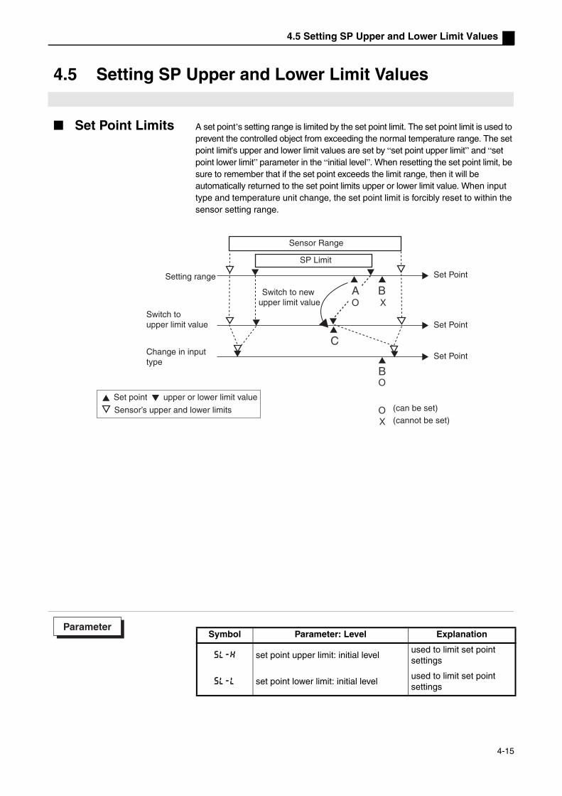
4.5 Setting SP Upper and Lower Limit Values
4.5 Setting SP Upper and Lower Limit Values
Set Point Limits A set point’s setting range is limited by the set point limit. The set point limit is used to prevent the controlled object from exceeding the normal temperature range. The set point limit's upper and lower limit values are set by “set point upper limit” and “set point lower limit” parameter in the “initial level”. When resetting the set point limit, be sure to remember that if the set point exceeds the limit range, then it will be automatically returned to the set point limits upper or lower limit value. When input type and temperature unit change, the set point limit is forcibly reset to within the sensor setting range.
Sensor Range
Switch to new upper limit value
SP Limit
Setting range
Switch to upper limit value
Change in inputtype
Set Point
Set Point
Set Point
(can be set)(cannot be set)
Set point upper or lower limit value
Sensor’s upper and lower limits
Symbol Parameter: Level Explanation
sl-h set point upper limit: initial levelused to limit set point settings
sl-l set point lower limit: initial levelused to limit set point settings
Parameter
4-15

Chapter 4 Applied Operations
Settings By setting the “set point upper limit”and “set point lower limit” parameters in the “initial level”, the set points upper and lower lower limit values can be set. This example describes how to set “-200°C ~ 1300°C” range K type thermocouple input limit settings at “-100°C ~ 1000°C”.
Setting Set Point Upper Limit
Set the “set point upper limit” parameter to “1000”.
(1) Press the key for 3 seconds or more, switch from the “initial level” to the “operations level”.
(2) Select “set point upper limit”.
(3) Use the UD key to set the parameter to “1000”.
Setting Set Point Lower Limit
Set the “set point lower limit” parameter to “-100”.
(1) In the “initial level” select “set point lower limit”.
(2) Use the UD key to set the parameter to “-100”.
Sensor Range
Setting Limiter
in-t
5
sl-h
1300
C
sl-h
1000
C
l.ini
l.ini
l.ini
OperationProcedure
Initial Setting Level
Input Type
Setting Upper Limit
5l-l
-200
C
5l-l
-100
C
l.ini
l.ini
OperationProcedure
Set Point Lower Limiit
4-16
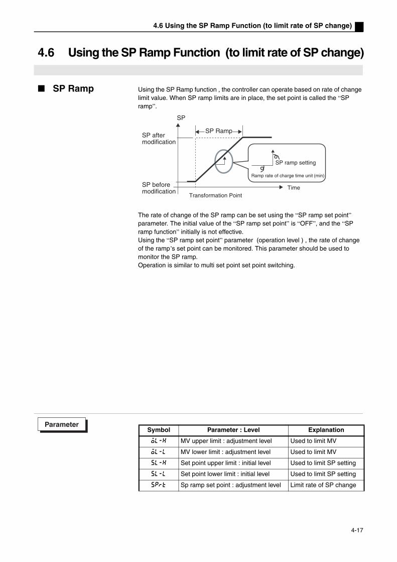
4.6 Using the SP Ramp Function (to limit rate of SP change)
4.6 Using the SP Ramp Function (to limit rate of SP change)
SP Ramp Using the SP Ramp function , the controller can operate based on rate of change limit value. When SP ramp limits are in place, the set point is called the “SP ramp”.
The rate of change of the SP ramp can be set using the “SP ramp set point” parameter. The initial value of the “SP ramp set point” is “OFF”, and the “SP ramp function” initially is not effective. Using the “SP ramp set point” parameter (operation level ) , the rate of change of the ramp’s set point can be monitored. This parameter should be used to monitor the SP ramp.Operation is similar to multi set point set point switching.
SP
SP Ramp
SP ramp setting
(min)
SP after modification
SP beforemodification
Ramp rate of charge time unit
TimeTransformation Point
Symbol Parameter : Level Explanation
ol-h MV upper limit : adjustment level Used to limit MV
ol-l MV lower limit : adjustment level Used to limit MV
sl-h Set point upper limit : initial level Used to limit SP setting
sl-l Set point lower limit : initial level Used to limit SP setting
sprt Sp ramp set point : adjustment level Limit rate of SP change
Parameter
4-17

Chapter 4 Applied Operations
Getting Started If the SP ramp function is activated , when the E5EZ-PRR is turned on, or switched from “stop” to “run”, When the process value reaches the SP ramp set point, it follows the same method used when the set point changes.Under this condition, Before changing process value, controller will operate by process value as the setting value. The SP ramp direction will change according to the relationship between the process value and the set point.
SP Ramp Operation Limits
When the SP ramp finishes, auto-tuning begins. When control stops or has an error, the SP ramp function is not effective.
SP RampSP Ramp
Set Point
Power On
Time Time
Set Point
Power On
Same Rate of Change
4-18

4.7 Switching to the Advanced Function Level
4.7 Switching to the Advanced Function Level
In the initial setting level, the advanced function level is protected and cannot be accessed. To switch to the advanced function level, first cancel protection in the “protection level”. Please see “4.8 Using the Key Protection Level”.
(1) In the “operation level”, simultaneously press the and M keys for 3 seconds or more. * Key timing can be set using “protection level switching time” (advanced function level) .
(2) The controller will switch to the protection level and display “operation /
adjustment protection”.
(3) Press the M key once to switch to “initial/communications protection”.
(4) Set the set point to “0”.
(5) Simultaneously press the and M keys to return to the “operation level”.
(6) Press the key for 3 seconds or more to switch from the “operation level” to
the “initial level”.
(7) Press the M key , select thse “switch to advanced function level” parameter .
(8) Use the UD key to input the password (“-169”) , then press the M key or wait
2 seconds or more to switch from the “initial level” to the “advanced function
level”.
oapt
0
icpt
0
25
100
c
icpt
1
in-t
5
-169
init
off
l.prt
l.prt
l.prt
l.ini
l.ini
l.
100.0
Protection Level
“Run/Adjustment Protection”
“Initial/CommunicationsProtection”
PV/SP/Valve Open %
Input Type
Switch to AdvancedFunction Level
Operation Level
Initial Setting Level
Advanced Function Level
4-19

Chapter 4 Applied Operations
4.8 Using The Key Protection Level
Key Protection Press the and M keys simultaneously for 3 seconds or more to switch to the protection level.* Key timing can be set in the “protection level switch timing” (advanced function level).
The protection level protects parameters that are changed after operation starts to prevent accidental modification.
Protection level settings can use the parameter's range .
Operation /Adjustment Protection
The relationship between set point and protection range is shown below
When this parameter is set to “0”, no parameters are protected. The initial value is “0”.
Initial/Communication Protection
These protection level limits affect the initial level, communications level, and advanced function level.
Initial value is “1”.
Setting Modification Protection
This protection level protection setting will not be affected by panel keys.
The initial value is set to “OFF”.
Automatic/manual key protection
Using the protection A key.
The initial value is “OFF”.
oapt
0
l.prt
LevelSet Point
0 1 2 3
Operation
Level
Present Value
Set Point
Other × ×
Adjustment Level × × ×
icpt
1
l.prt
Set Point
Initial Level
Comm. Level
Advanced Function Level
0
1 ×
2 × × ×
wtpt
off
l.prt
Set Point Explanation
OFF Settings can be changed with keys.
ONSettings cannot be changed with keys. (protection level can be changed.)
keyp
off
l.prt
Set Point description
OFF Use the A key to switch between manual/automatic
ON Cannot use the A to switch between manual/automatic
:can be displayed and changed
:can be displayed× :cannot be displayed
or switched to other
:can switch to other levels
× :cannot switch to other levels
4-20

Chapter 5 Parameters
Chapter 5 Parameters
Contents of This Chapter ........................................................................5-2Definition of the symbols used in this chapter .........................................5-2Parameter display....................................................................................5-2Parameter explain order in this chapter...................................................5-2Manual Control Level...............................................................................5-3Protect Level............................................................................................5-5Operation Level .......................................................................................5-7Adjustment Level ...................................................................................5-12Initial Level.............................................................................................5-20Advanced Function Level ......................................................................5-28Communications Level ..........................................................................5-41
5-1

Contents of This Chapter
Contents of This Chapter
Definition of the symbols used in this chapter
Functions
Explaining parameter function.
Settings
Explaining setting range examples and parameter initial values.
Monitoring
Explaining monitoring ranges.
Examples
Explaining use of parameters.
Reference
Explaining related parameters and categories.
Parameter displayParameters can only be displayed if the conditions given to the right are met. Note that protected parameters are not displayed regardless of whether the conditions are met.
Parameter explain order in this chapterParameters are explained by level.Parameters that may be used in each level are given on the first page of each section. The names of the parameters are ordered according to the display sequence used by the E5EZ-PRR.
at l.adjRun/Cancel AT control must be 2-PID control.
Operation Conditions Setting Level (No. 3 display)
Parameter NamesDisplay Symbols
5-2

Manual Control Level
When using manual operation, this level is displayed.Setting valve open percentage.
Manual Control Level
Accessing the manual control level.In the operation /adjustment level, press the A key for 1 second or more to change to manual mode, i.e. switch to the manual control level. In the future during manual operation only “process value/set value/valve open percentage” will be displayed. When “process value/set value/valve open percentage” is displayed in the manual control level, press the A key for 1 second or more to switch to manual/auto mode, change to the operation level, and display the operation level’s initial data.
L
1
Input Power Supply
Operation Level Adjustment Level
Press key less than 1sec.
Press A key more than 1 sec.
Press A key more than 1 sec.
Press A key more than 1 sec. Auto Operation
Manual Control Level
Manual Operation
Switching from the manual control level to key control can only be done from the current operation level (initial values).
5-3
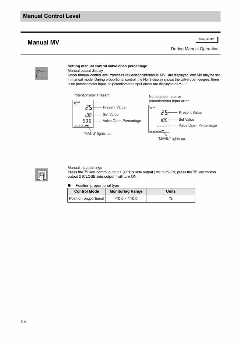
Manual Control Level
Manual Control Level
Setting manual control valve open percentageManual output displayUnder manual control level, “process value/set point/manual MV” are displayed, and MV may be set in manual mode. During proportional control, the No. 3 display shows the valve open degree; there is no potentiometer input, so potentiometer input errors are displayed as “----”.
Manual input settingsPress the U key, control output 1 (OPEN side output ) will turn ON; press the D key control output 2 (CLOSE side output ) will turn ON.
Position proportional type
Manual MVManual MV
During Manual Operation
25
100
c
50.0
25
100
c
----
Potentiometer Present
Present Value
Set Value
Valve Open Percentage
“MANU” lights up.
No potentiometer or potentiometer input error
Present Value
Set Value
Valve Open Percentage
“MANU” lights up.
Control Mode Monitoring Range Units
Position proportional -10.0 ~ 110.0 %
5-4

Protect Level
The E5EZ-PRR provides 4 protect functions, namely “Operation/Adjustment Protect”, “Initial Setting/Communications Protect”, “Setting Change Protect”. These 4 protect functions prevent unintentional changes from occurring when panel keys are pressed.
Protect Level
To switch from Operation Level to Protect Level by pressing and M key more than 3 seconds.
Setting of protected parameter are not displayed, therefore they cannot be changed.
25
100
c
100.0
Input Power Supply
Operation Level Adjustment Level
Press key less than 1sec.
Press key more than 1 sec.
Press key more than 3 sec.
Protect Level
Control in Progress
oapt
0
icpt
1
wtpt
off
l.prt
l.prt
l.prt
keyp
off
l.prt
5-6
5-6
5-6
5-6
Protect Level
Operation / Adjustment Protect
Initial Setting/Communications Protection
Setting Change Protect
Automatic/Manual Key Protect
Page No.
5-5

Protect Level
Protect Level
This parameter determines the range of parameters protected. indicates the initial value.
Operation/adjustment protect
The relationship between set points and protect range is shown below.
When the set point is “0”, there is no protect function . Initial /communications protect
Restricts access to the “initial level”, “communications level” and “advanced function
level”.
Setting Change Protect
Limits the ability to change settings by pressing keys.
Auto/manual key protect
Protect A key operations
Operation/Adjustment Protect
Initial /Communications Protect
Setting Change Protect
Automatic/Manual Key Protect
l.prt
k
Functions
Note
LevelSet Point
0 1 2 3
Operation level
Process value
Set Point
Other × ×
Adjustment level × × ×
Set Point
Initial Level
Communications Level
Advanced Function
Level
0
1 ×
2 × × ×
Set Point Explanation
OFF Limits the ability to change settings by pressing keys.
ONDoesn't limit the ability to change settings by pressing keys (Protect Level can be changed.)
Set Point Explanation
OFF The A key can be used to switch automatic/manual
ONThe A key cannot be used to switch between automatic/manual
: can switch to other levels× : cannot switch to other
levels
: display/change: Yes : display: Yes× : Cannot display or switch to
level
5-6

Operation Level
When the E5EZ-PRR is engaged in control, this level is displayed. Alarm values and monitor MV can be set in this level.
Operation Level
When the E5EZ-PRR is turned on, this level will be displayed automatically. Press the key or and M key to switch to other levels.
25
100
100.
c
0
Input Power Supply
Operation Level Adjustment Level
Press key less than 1sec.
Press key more than 3 sec.
Press key more than 1 sec.
Press key less than 1sec.
Control in progress
Control stopped
Control Stopped
Communications
LevelInitial Setting Level
Press key more than 1 sec. display will blink
M
M
5-8 5-11
5-11
5-10
5-11
5-11
5-8
5-8
5-9
5-9
5-10
25c
25
100
c
M
m-sp
0
c
M
sp-m
0
c
M
r-s
run
c
M
al-1
0
c
M
M
al1h
0
c
al1l
0
c
M
al-2c
M
al2hc
M
al2lc
0
0
0
Alarm value 2
0100.
Operation level
Present value/set value/valve open percentage
Present value
Multi-SP
SP ramp set value
Run/Stop
Alarm value 1
Upper limit alarm value 2
Lower limit alarm value 2
Upper limit alarm value 1
Lower limit alarm value 1
Page No. Page No.
5-7

Operation Level
Operation Level
Functions
The process value is displayed on No.1 display but not No.2 or No.3 displays.
Monitoring
Reference
Related parameters“input type” (initial level) (p. 5-21) “set point upper limit”, “set point lower limit” (initial level) (p. 5-23)
Functions
Process value is displayed on no. 1 display, set point is displayed on no. 2 display, and valve open percentage on no. 3 display.
Decimal point position depends on sensor type being used.
Reference See process value parameter.
Functions
Multiple set point allows the user to set 4 set points in the adjustment level (set points 0 through 3) . These values can be switched by pressing keys on the panel or by external input signals. In the parameter, input set points 0 through 3.
Process Value “Add process value display” parameter must be “ON”。
Monitor range Units
Process value
Input indicator range (see p.5-21) EU
Process value/set value/valve open percentage
Monitor Range Setting Range Units
Process value Input indicator range (see p.A-10) EU
Set pointSet point lower limit ~ Set point upper limit
EU
Valve open penentage
10.0~110.0% %
Multiple set point (set points 0 through 3)
Event input ON:parameter “number of multi SP used” must be set to “0”Parameter “number of multi SP used” must be set to “ON”
Event inputOFF:
parameter “number of multi SP used” must be set to “ON”
None Display
None Display
5-8
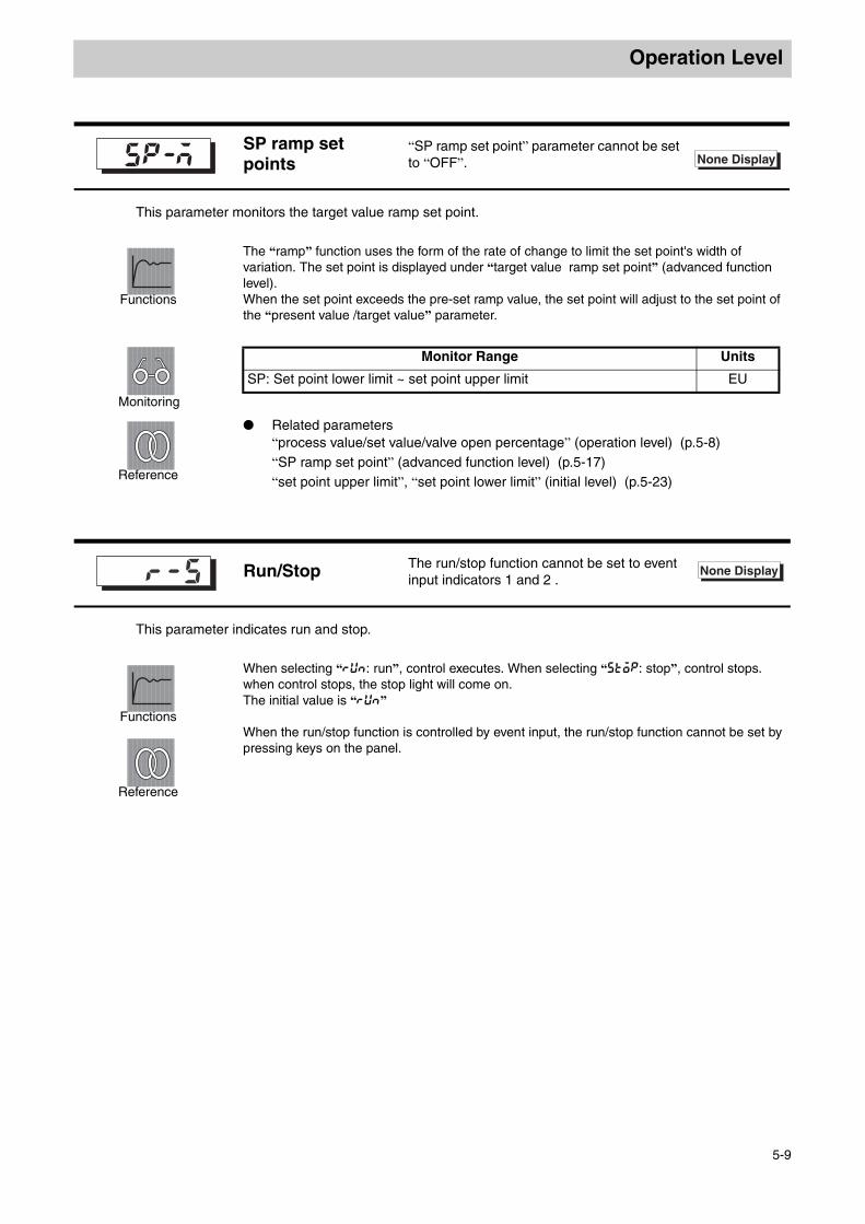
Operation Level
This parameter monitors the target value ramp set point.
Functions
The “ramp” function uses the form of the rate of change to limit the set point's width of variation. The set point is displayed under “target value ramp set point” (advanced function level).When the set point exceeds the pre-set ramp value, the set point will adjust to the set point of the “present value /target value” parameter.
Monitoring
Reference
Related parameters“process value/set value/valve open percentage” (operation level) (p.5-8) “SP ramp set point” (advanced function level) (p.5-17) “set point upper limit”, “set point lower limit” (initial level) (p.5-23)
This parameter indicates run and stop.
Functions
When selecting “run: run”, control executes. When selecting “stop: stop”, control stops. when control stops, the stop light will come on.The initial value is “run”
Reference
When the run/stop function is controlled by event input, the run/stop function cannot be set by pressing keys on the panel.
SP ramp set points
“SP ramp set point” parameter cannot be set to “OFF”. None Display
Monitor Range Units
SP: Set point lower limit ~ set point upper limit EU
Run/Stop The run/stop function cannot be set to event input indicators 1 and 2 .r-5 None Display
5-9

Operation level
Operation level
This parameter is listed under alarm type, setting input value “X”.
Functions
This parameter is used to set the alarm output 1, 2 alarm value . With temperature input, the decimal point is determined by the sensor currently in
use. With analog signal input, the decimal point is determined by the “decimal point” parameter.
Settings
Reference
The alarm type must be set to something other than upper or lower limit alarm. Related parameters
“Input type” (initial level) (p. 5-21), “scaling upper limit”, “scaling lower limit”, “decimal point” (initial level) (p. 5-22)“Alarm 1 and 2 type” (initial level) (p. 5-24)“Activate alarm 1 and 2 on alarm” “alarm 1 and 2 hysteresis” (from p.5-32 to p.5-33) “standby sequence reset” (p. 5-31) , “alarm latch” (p. 5-36) (advanced function level)
Alarm value 1
Alarm value 2Alarm type must be set to no alarm or upper or lower limit, upper or lower limit range or other than attached standby order sequence upper or lower limit.
Setting range Units Initial value
-1999~9999 EU 0
None Display
5-10

Operation Level
When alarm 1 type (initial level) is set to upper or lower limit mode, this parameter is independently set to the upper or lower limit alarm value.
Functions
This parameter is set to alarm 1 upper or lower limit value. During the temperature input period, decimal point location is related to the sensor
currently in use. With analog signal input, the decimal point is determined by the “decimal point” parameter.
Settings
Reference
Related parameters“alarm 1 type” (initial level) (p. 5-24)“standby sequence reset ” (p. 5-31) , “activate alarm 1 on alarm”, “alarm 1 hysteresis” (p. 5-32) , “alarm 1 latch” (p. 5-36) (advanced function level)
When alarm 2 type (initial level) is set to upper or lower limit mode, this parameter is independently set to the upper or lower limit alarm value.
Functions
This parameter is set to alarm 2 upper or lower limit value. During the temperature input period, decimal point location is related to the sensor
currently in use. With analog signal input, the decimal point is determined by the “decimal point” parameter.
Settings
Reference
Related parameters “Alarm 2 type” (initial level) (p. 5-24)“Standby sequence reset” (p. 5-31) , “activate alarm 2 on alarm”, “alarm 2 hysteresis” (p. 5-32) , “alarm 2 latch” (p. 5-36) (advanced function level)
Upper limit alarm value 1
Upper limit alarm value 2Alarm 1 type must be set to upper or lower limit, upper or lower limit range or attached the standby sequence upper or lower limit alarm.
Setting Range Units Initial Value
-1999~9999 EU 0
Upper limit alarm value 2
Lower limit alarm value 2Alarm 2 type must be set to upper or lower limit, lower limit range or near the standby sequence upper or lower limit alarm.
Setting Range Units Initial Value
-1999~9999 EU 0
None Display
None Display
5-11

Adjustment Level
This level is used for AT (auto-tuning ) or setting control.This level provides basic controller parameter settings for use with PID (proportional band, integral time and derivative time) .
Adjustment LevelPress the key for less than 1 second to switch from the operation level to the adjustment level. Adjustment level set points 0 ~ 3, are the set points used during transfer between multiple set point input. By setting the operation /adjustment protect to “0”, the adjustment level parameters can be changed. If the
protect level is set to values from “1” ~ “3” value, the adjustment level parameter will not be displayed.
Input Power Supply
Press key less than 1sec.
Operation Level Adjustment Level
Control in progress
5-13
5-13
5-14
5-14
5-14
5-14
5-15
5-15
5-15
5-16
5-16
5-16
5-17
5-17
5-17
5-18
5-18
5-18
5-19
l. adj l. adj
l. adj
l. adj
l. adj
l. adj
l. adj
l. adj
l. adj
l. adj
l. adj
l. adj
l. adj
l. adj
l. adj
l. adj
l. adj
l. adj
l. adj
Adjustment Level
Run/Stop AT
Communications Writing
SP 0
SP 1
SP 2
SP 3
Temperature Input Shift
Upper Limit Temperature Input Shift
Lower Limit Temperature Input Shift
Proportional Band
Page No. Page No.Integral Time
Derivative Time
MV When Stopped
PV Error MV
SP Ramp Setting Value
MV Upper Limit Value
MV Lower Limit Value
Position Proportional Dead Band
ON/OFF Delay
5-12

Adjustment Level
Adjustment Level
This parameter executes AT (auto-tuning ) .
Functions
During auto-tuning, by forcibly changing the MV, the controlled object's unique values are calculated, and optimal set point PID parameters are automatically set (“proportional band”, “integral time” and “derivative time”) .
Examples
Under normal conditions, this parameter is set to “off”. press U or D, to open the parameter, and execute AT.
After AT finishes, this parameter automatically returns to “off”.
Reference
Related parameters“proportional band”, “integral time”, “derivative time” (adjustment level) (p. 5-16)
Functions
This parameter starts/stops the host (superior computer), from using communications to write to the temperature controller's parameter function .
Settings
ON : activate writingOFF : deactivate writinginitial value is OFF
Reference
Related parameters“MB command logic switching” (advanced function level) (p. 5-38)“communications unit No.”, “baud rate”, “data length”, “communication parity”, “stop bit” (communications level) (p. 5-42)
AT Execute/Cancel operation level/adjustment level/protect level operation l.adj
communications writing The communications unit must be installed.cmwt l.adj
5-13

Adjustment Level
When using the multiple set point function, these parameters are used to set multiple set points.
Functions
Using the panel’s keys or event input, select set points for these parameters. After set points are changed, multiple set point’s current parameter set point’s can be
linked and changed. During the temperature input, decimal point location is related to the sensor currently
in use.With analog signal input, the decimal point is determined by the “decimal point” parameter.
Settings
Reference
Related parameters“number of multi SP used” (advanced function level) (p. 5-29)“event input indicator 1” (advanced function level) (p. 5-30)“event input indicator 2” (advanced function level) (p. 5-30)“Multi SP used” (advanced function level) (p. 5-31)“process value” (operation level) , “process value/set point” (operation level) (p. 5-8)“Input type” (initial level) (p. 5-21)
Set Point 0set point 0 and 1
Set Point 1event input
ON: “number of multi SP used” set to 1 or 2, or “number of multi SP used” set to 0 “multiple settings” set to 「ON」 .
event input
OFF:
“multiple set point used” set to 「ON」 .
Set Point 2 set point 2 and 3event input
ON: “number of multi SP used” set to 2, or “number of multi SP used” set to 0 “multiple settings” set to 「ON」 .
Set Point 3 event input
OFF:
“multiple set point used” set to 「ON」 .
l.adj
Setting Range Units Initial Value
set point lower limit ~ set point upper limit
EU 0
5-14

Adjustment Level
Adjustment Level
Sometimes the measured value may be different from the actual temperature. To compensate for this difference, the input shift value and input measured value can be added together and displayed as the measured value, and used for control.
Functions
The entire input range uses a fixed numeric shift (1 point shift) . If the input shift value is set to “-1.0°C”, then the measured temperature value deducts 1.0°C before being displayed as the measured value.
Settings
Reference
Related parameters“input type” (initial level) (p.5-21)
1 point shift uses the “temperature input shift” parameter to apply a fixed shift the entire input range, and 2 point shift uses two point (upper limit and lower limit) to shift the input range. By setting the upper or lower limi input shift value to a different value , 2 point shift can be more accurate than 1 point shift in compensating for the input range.
Functions
These parameters set the shift values of the upper limit and lower limit of the input range respectively (2 point shift).
Settings
Reference
Related parameters“input type” (initial level) (p. 5-21)
Temperature Input Shift Value
Temperature input type “input type” parameter must be set to temperature input, but not for non-contact temperature sensors.
l.adj
Setting Range Units Initial Value
-199.9~999.9 °C or °F 0.0
Upper Limit Temperature Input Shift Value
Lower Limit Temperature Input Shift Value
Temperature input type “input type” parameter can only be set to non-contact temperature sensor.
l.adj
Monitor Range Units Initial Value
-199.9~999.9 °C or °F 0.0
5-15

Adjustment Level
This parameter can be set as a PID parameter. Note that when using AT, the PID will be set automatically.
Functions
Settings
Reference
Related parameters“activate/deactivate AT” (adjustment level) (p. 5-13)
Proportional Band
Integral Time
Derivative Time
l.adj
Using Proportional:
P refers to MV and deviation zone direct proportional control (control errors) .
Using integrals:
I provides control error integral time proportional control control. During proportional control integral deviation occurs frequently (control discrepancies) . So proportional and integral are used together.After a period of time, control discrepancies vanish and the set point matches the control temperature (process value).
Using derivatives:
D provides control error derivative time proportional control. Because proportional control and integral control correct control errors, the control system will delay reaction to sudden temperature changes temperature. derivative control makes use of pre-measured output proportional control, to facilitate correction of errors in advance.
Parameters Setting Range Units Initial Value
proportional band
temperature input: 0.1~999.9 EU 8.0
analog input: 0.1~999.9 %FS 10.0
integral timefloating:1~3999
second 233closed: 0~3999
derivative time 0~3999 second 40
5-16

Adjustment Level
Adjustment Level
Functions
“MV when stopped” refers to MV when operation has stopped (off/hold/on) . “MV during error” refers to operation during error (off/hold/on) .
Settings
Position proportional type
Functions
This parameter specifies the rate of change of the SP ramp. Allow each unit time (min) maximum change width to be set to “SP ramp set point”. But note that when SP ramp set point is set to “OFF”, SP ramp function is not effective.
With temperature input, the SP ramp set value’s decimal point is determined by the sensor currently in use. During analog signal input, it is related to scaling.
Settings
Reference
Related parameters“input type” (p. 5-21) , “scaling upper limit”, “scaling lower limit” “decimal point ”, (p. 5-22) .
MV When Stopped
MV During Error “stop/error add MV” must be set to “ON”
l.adj
Setting Range Units Initial Value
hold: hold/open: open/clos: close none hold
SP ramp set point sprt l.adj
Parameters Setting Range Units Initial Value
SP ramp set value OFF,1~9999 EU OFF
5-17

Adjustment Level
Functions
The “MV upper limit” and “MV lower limit” parameter are used to set the MV upper and lower limits. When the MV value calculated by the E5EZ-PRR exceeds the upper or lower limit value, the upper limit or lower limit is set to the output limit.
Settings
MV upper limit
Reference
MV upper limit
Functions
Setting position proportional control output hold period (he time it takes OPEN output and CLOSE output switch from ON to OFF) .
Settings
Reference
Related events3.8 ceramic kiln position proportional control
Position proportional control fixed settings (p. 3-20).
MV Upper Limit
MV Lower Limit
ol-h l.adj
ol-l
Control Mode Setting Range Units Initial Value
standard MV lower limit +0.1~105.0 % 100.0
Control Mode Setting Range Units Initial Value
standard 0.5 ~ MV upper limit -0.1 % 0.0
Position proportional dead band db l.adj
Setting Range Units Initial Value
Floating: 0.1~10.0 % 2.0
Closed: 0.1~10.0 % 4.0
5-18

Adjustment Level
Adjustment Level
Functions
With position proportional control, the OPEN and CLOSE output ON, OFF switching uses hysteresis.
Settings
Reference
Related events3.8 ceramic kiln position proportional control
Position proportional control fixed settings (p. 3-20).
Hysteresis off/on oc-h l.adj
Setting Range Units Initial Value
0.1~20.0 % 0.8
5-19
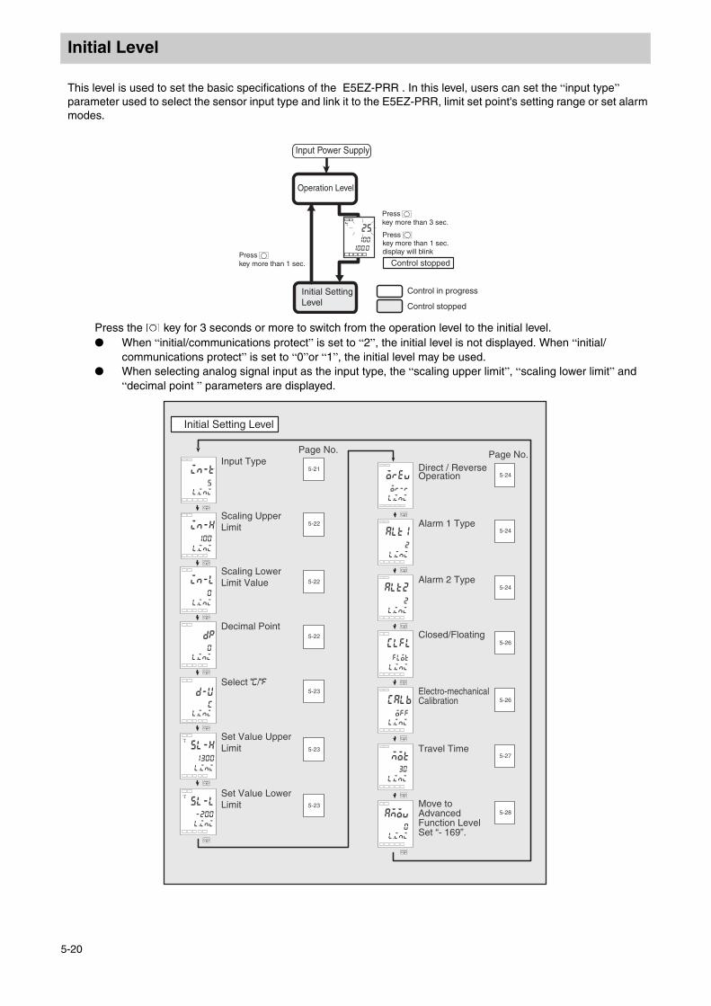
Initial Level
This level is used to set the basic specifications of the E5EZ-PRR . In this level, users can set the “input type” parameter used to select the sensor input type and link it to the E5EZ-PRR, limit set point's setting range or set alarm modes.Initial Level
Press the key for 3 seconds or more to switch from the operation level to the initial level. When “initial/communications protect” is set to “2”, the initial level is not displayed. When “initial/
communications protect” is set to “0”or “1”, the initial level may be used. When selecting analog signal input as the input type, the “scaling upper limit”, “scaling lower limit” and
“decimal point ” parameters are displayed.
25
100
c
100.0
Input Power Supply
Operation Level
Press key more than 3 sec.
Press key more than 1 sec. display will blink
Control in progress
Control stopped
Control stoppedPress key more than 1 sec.
Initial Setting Level
5-21
5-22
5-22
5-23
5-22
5-23
5-23
M
in-t
5
l.ini
M
in-h
100
M
in-l
0
M
dp
0
M
5l-h
1300
c
M
M
5l-l
-200
c
M
d-u
c
or-r
M
alt1
2
M
alt2
2
M
0
M
calb
off
M
M
clfl
flot
M
mot
30
5-24
5-24
5-24
5-26
5-26
5-27
5-28
l.ini
l.ini
l.ini
l.ini
l.ini
l.ini
l.ini
l.ini
l.ini
l.ini
l.ini
l.ini
l.ini
Initial Setting Level
Page No. Page No.Input Type
Scaling Upper Limit
Scaling Lower Limit Value
Decimal Point
Select C/F
Set Value Upper Limit
Set Value Lower Limit
Direct / Reverse Operation
Alarm 1 Type
Alarm 2 Type
Closed/Floating
Electro-mechanical Calibration
Travel Time
Move to Advanced Function LevelSet “- 169”.
5-20

Initial Level
Initial Level
Functions
By using the appropriate code, this parameter can set the sensor type . After changing parameters, the set point upper limit becomes the initial value. If
changing the set point limit range, users can set the “set point upper limit” and “set point lower limit” parameters (initial level).
Settings
Set code according to the following table. The shaded area represents the initial setting.
Temperature input: E5EZ-PRR2 T
Analog input type: E5EZ-PRR2 L
Input Type l.adjl.ini
Input Type Name Set Point Input Temperature Range
platinum resistance
thermometer
Pt100
0 -200 ~ 850 (°C) /-300 ~ 1500 (°F)
1 -199.9 ~ 500.0 (°C) /-199.9 ~ 900.0 (°F)
2 0.0 ~ 100.0(°C) /0.0 ~ 210.0 (°F)
JPt1003 -199.9 ~ 500.0 (°C) /-199.9 ~ 900.0 (°F)
4 0.0 ~ 100.0 (°C) /0. 0 ~ 210.0 (°F)
thermocouple
K5 -200 ~ 1300 (°C) /-300 ~ 2300 (°F)
6 -20.0 ~ 500.0 (°C) /0.0 ~ 900.0 (°F)
J7 -100 ~ 850 (°C) /-100 ~ 1500 (°F)
8 -20.0 ~ 400.0 (°C) /0.0 ~ 750.0 (°F)
T9 -200 ~ 400 (°C) /-300 ~ 700 (°F)
22 -199.9 ~ 400.0 (°C) /-199.9 ~ 700.0 (°F)
E 10 0 ~ 600 (°C) /0 ~ 1100 (°F)
L 11 -100 ~ 850 (°C) /-100 ~ 1500 (°F)
U12 -200 ~ 400 (°C) /-300 ~ 700 (°F)
23 -199.9 ~ 400.0 (°C) /-199.9 ~ 700.0 (°F)
N 13 -200 ~ 1300 (°C) /-300 ~ 2300 (°F)
R 14 0 ~ 1700 (°C) /0 ~ 3000 (°F)
S 15 0 ~ 1700 (°C) /0 ~ 3000 (°F)
B 16 100 ~ 1800 (°C) /300 ~ 3200 (°F)
Non-contact Temperature Sensor ES1B
10°C ~ 70°C 17 0 ~ 90 (°C) /0 ~ 190 (°F)
60°C ~120°C 18 0 ~ 120 (°C) /0 ~ 240 (°F)
115°C ~ 165°C
19 0 ~ 165 (°C) /0 ~ 320 (°F)
140°C ~ 260°C
20 0 ~ 260 (°C) /0 ~ 500 (°F)
analog signal input
0 ~ 50mV 21The following variation ranges are related
to calibration results -1999 ~ 9999, -199.9 ~ 999.9
Input Type Name Set Point Input Temperature RangeCurrent 4 ~ 20mA 0 Depending on scaling, use in one of
these ranges:-1999 ~ 9999, -199.9 ~ 999.9, -19.99 ~ 99.99, -1.999 ~ 9.999
0 ~ 20mA 1Voltage 1 ~ 5V 2
0 ~ 5V 30 ~ 10V 4
5-21
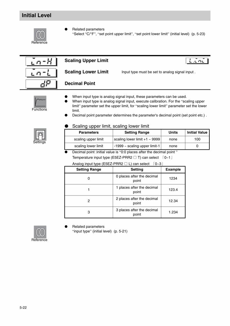
Initial Level
Reference
Related parameters“Select °C/°F”, “set point upper limit”, “set point lower limit” (initial level) (p. 5-23)
初始菜单
Functions
When input type is analog signal input, these parameters can be used. When input type is analog signal input, execute calibration. For the “scaling upper
limit” parameter set the upper limit, for “scaling lower limit” parameter set the lower limit.
Decimal point parameter determines the parameter's decimal point (set point etc.) .
Settings
Scaling upper limit, scaling lower limit
Decimal point :initial value is “0:0 places after the decimal point ”Temperature input type (E5EZ-PRR2 T) can select 「0~1」
Analog input type (E5EZ-PRR2 L) can select 「0~3」
Reference
Related parameters“input type” (initial level) (p. 5-21)
Scaling Upper Limit
Scaling Lower Limit Input type must be set to analog signal input .
Decimal Point
l.adjl.ini
Parameters Setting Range Units Initial Value
scaling upper limit scaling lower limit +1 ~ 9999 none 100
scaling lower limit -1999 ~ scaling upper limit-1 none 0
Setting Range Setting Example
00 places after the decimal
point 1234
11 places after the decimal
point 123.4
22 places after the decimal
point 12.34
33 places after the decimal
point 1.234
5-22

Initial Level
Initial Level
Functions
Set temperature input unit to “°C”or “°F”
Settings
Reference
Related parameters“Input type” (initial level) (p. 5-21)
Functions
By setting the set points, this parameter can be used to limit upper or lower limit values. Using the “set point upper limit” and “set point lower limit” parameters, set the set point within the upper or lower limit set point specification range. If the current set point exceeds the range, it will be forcibly returned to either the upper limit value or lower limit value (whichever is closest).
When the temperature input type and temperature unit are changed, the set point upper limit and set point lower limit will be forcibly returned to the sensor's upper or lower limit value.
With temperature input, the decimal point is determined by the sensor currently in use. During analog signal input, it is related to scaling.
Temperature input: E5EZ-PRR2 T
Settings
Analog input type: E5EZ-PRR2 L
Reference
Related parameters“input type” (p. 5-21), “select °C/°F” (p. 5-23) (initial level)
Select °C/°F Input type must be set to temperature input l.adjl.ini
Setting Range Initial Value
c:°C/f: °F c
Set Point Upper Limit
Set Point Lower Limit
l.ini
Parameters Setting Range Units Initial Value
Set point upper limit
Set point lower limit +1 is the sensor range upper limit
EU 1300
Set point lower limit
Sensor range lower limit is the set point upper limit-1
EU -200
Parameters Setting Range Units Initial Value
Set point upper limit
Set point lower limit +1 is the sensor range upper limit
EU 100
Set point lower limit
Sensor range lower limit is the set point upper limit -1
EU 0
5-23
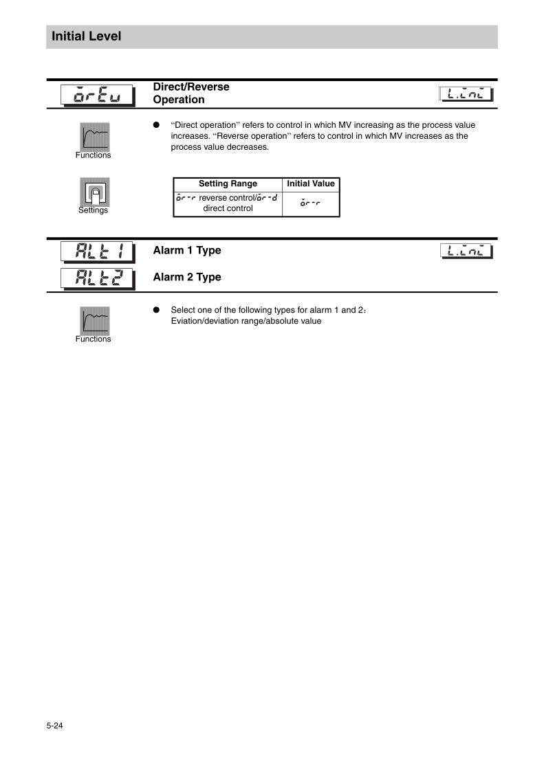
Initial Level
Functions
“Direct operation” refers to control in which MV increasing as the process value increases. “Reverse operation” refers to control in which MV increases as the process value decreases.
Settings
Functions
Select one of the following types for alarm 1 and 2:Eviation/deviation range/absolute value
Direct/Reverse Operation
l.adjl.ini
Setting Range Initial Value
or-r reverse control/or-d direct control
or-r
Alarm 1 Type
Alarm 2 Type
l.ini
5-24

Initial Level
Settings
Reference
For “alarm 1 and 2 type” parameter (Initial Level) , the alarm type of each alarm may be set independently. Initial value is “2:upper limit alarm”.
Related parameters“alarm value 1 and 2” (Operation Level ) (p. 5-10)“upper limit alarm value 1 and 2”, “lower limit alarm value 1 and 2” (Operation Level ) (p. 5-11)“Standby Sequence Reset” (p. 5-31), “activate alarm 1, 2 and 3 on alarm”, “alarm 1, 2 and 3 hysteresis” (p. 5-32 and 5-33) , “alarm 1, 2 latch” (p. 5-36) (Advanced Function Level)
*4
*3
*2
0
1
2
3
4
5
6
7
8
9
10
11
ONOFF
L H
SP
XONOFF
SP
XONOFF
SP
SP
ONOFF
X
X
X
ONOFF
SP
SP
ONOFF
XONOFF
SP
XONOFF
SP
XONOFF
SP
ONOFF
L H
SP
ONOFF
L H
SP*5
XONOFF
0
XONOFF
0
XONOFF
0
XONOFF
0
XONOFF
0
XONOFF
0
XONOFF
0
XONOFF
0
Output OFF
*1
*1
*1
*1:
*2:
Case 1
*3:
*4:*
--
*5:
Set Value Alarm type
X is positive X is negative
No alarm function
upper and lower limits
upper limits
lower limits
upper and lower limit range
standby sequence upperand lower limits
standby sequence upperlimits
standby sequence lowerlower limits
absolute value upper limit
absolute value lower limit
standby sequence absolute value upper limit
standby sequence absolute value lower limit
“L” and “H” represent the upper limit value and lower limit value, alarm points can be set independently for values 1, 4 and 5.Setting value 1 upper and lower limit alarm
Case 2 Case 3
Set value: 4 upper and lower limit range alarmCase 1 Case 2 Case 3
Set value: standby sequence 5 upper and lower limit alarm
Set value: standby sequence 5 upper and lower limit alarm
Used with the upper and lower limit alarms described aboveIn cases 1 and 2, if the upper and lower hysteresis limit values overlap, the alarm will always be off.In case 3, the alarm will always be off.
If hysteresis upper and lower limit values overlap, the alarm will always be on.
Alarm Input Operation
5-25
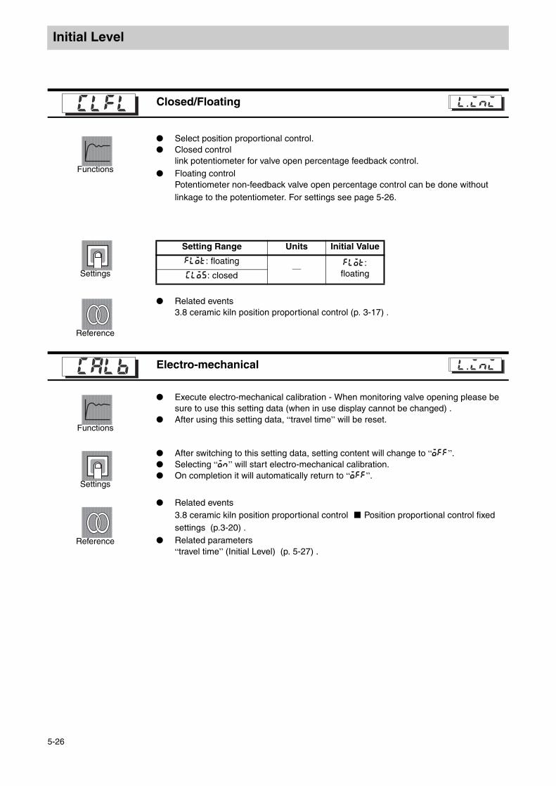
Initial Level
Initial Level
Functions
Select position proportional control. Closed control
link potentiometer for valve open percentage feedback control. Floating control
Potentiometer non-feedback valve open percentage control can be done without linkage to the potentiometer. For settings see page 5-26.
Settings
Reference
Related events3.8 ceramic kiln position proportional control (p. 3-17) .
Functions
Execute electro-mechanical calibration - When monitoring valve opening please be sure to use this setting data (when in use display cannot be changed) .
After using this setting data, “travel time” will be reset.
Settings
After switching to this setting data, setting content will change to “off”. Selecting “on” will start electro-mechanical calibration. On completion it will automatically return to “off”.
Reference
Related events3.8 ceramic kiln position proportional control Position proportional control fixed settings (p.3-20) .
Related parameters“travel time” (Initial Level) (p. 5-27) .
Closed/Floatingclfl l.adjl.ini
Setting Range Units Initial Value
flot: floating—
flot: floatingclos: closed
Electro-mechanicalcalb l.adjl.ini
5-26
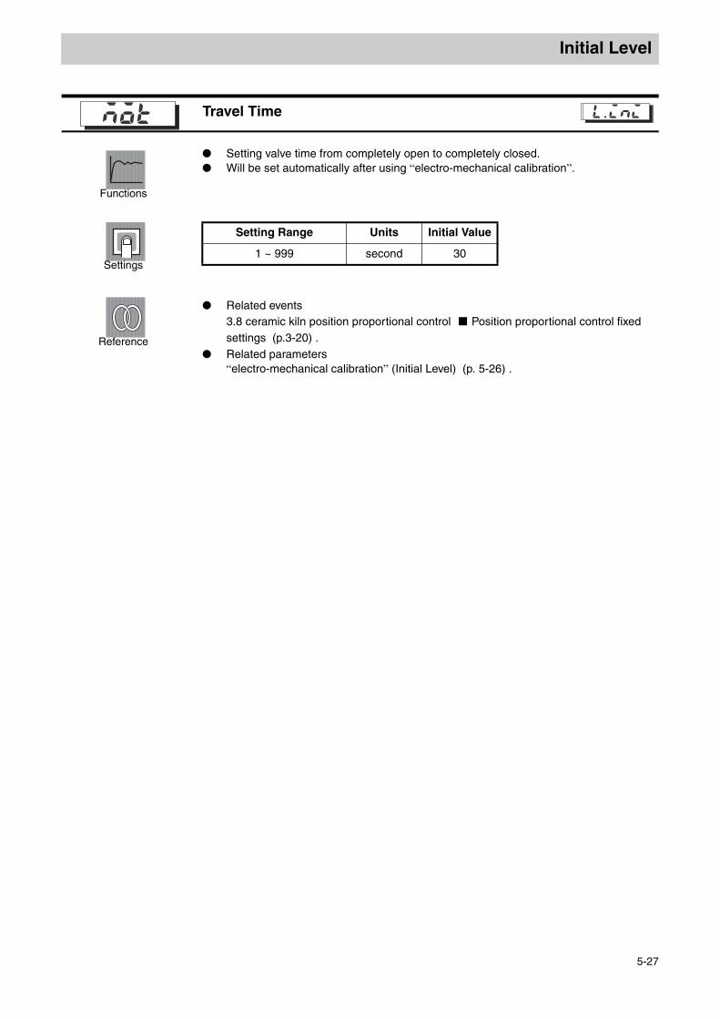
Initial Level
Initial Level
Functions
Setting valve time from completely open to completely closed. Will be set automatically after using “electro-mechanical calibration”.
Settings
Reference
Related events3.8 ceramic kiln position proportional control Position proportional control fixed settings (p.3-20) .
Related parameters“electro-mechanical calibration” (Initial Level) (p. 5-26) .
Travel Timemot l.adjl.ini
Setting Range Units Initial Value
1 ~ 999 second 30
5-27

Advanced Function Level
Advanced Function LevelThis permits the maximum use of the E5EZ-PRR’s functions. In the “Initial Level” enter the password (“-169”) to switch to this level. When entering password, “initial/communications protect” setting value must be set to “0”.
When the “initial/communications protect” setting values are set to “0”, this level’s parameters can be used.
Press the key to change between setting levels. Press the UD key to change setting values.
25
100
c
100.0
Input Power Supply
Operation Level Adjustment Level
Press key more than 1 sec.
Press key less than 1 sec.
Press key more than 3 sec.
Press key more than 1 sec.
Press key less than 1 sec.
Initial setting level
key No. 1 display
Control Stop
Communications Level
Input password set value “-169”
Advanced Function Level
Control in progress
Control stopped
5-29
5-29
5-30
5-30
5-31
5-31
5-32
5-32
5-33
5-33
5-34
5-34
5-35
5-35
5-36
5-36
5-36
5-37
5-37
5-38
5-38
5-38
5-38
5-38
5-39
5-39
5-40
5-40
M
M
al2n
n-o
M
alh2c
M
alfa
M
inf
M
alh1
02
c
.
02.
.
.
M
a2lt
off
M
prlt
M
sero
cjc
M
a1lt
off
3
on
off
M
a1of
0
M
a2on
0
Advanced Function Level
Parameter Initialization
Number of Multi SP Used
Event Input Indication 1
Event Input Indication 2
Number of Multi SP Used
Standby Sequence Reset Method
Alarm 1Open in Alarm
Alarm 1 Delay
Alarm 2 Open in Alarm
Alarm 2 Delay
Input Digital Filter
Additional Present Value Display
Display Mode AutomaticDisplay ReturnTime
Alarm 1 Latch
Alarm 2 Latch
Protect Level Switching Time
Output / Input Error
Cold Junction Compensation Method
MB Command Logic Switching
Alarm 1 ON Delay
Alarm 2 ON Delay
Alarm 1 OFF Delay
Alarm 2 OFF Delay
Stop/Error Add MV
Present Value Dead Band
Valve Opening Display
Manual MV Limit In Effect
Page No. Page No. Page No. Page No.
5-28

Advanced Function Level
Advanced Function Level
Functions
This parameter is used to return parameters to their initial values.
Settings
ON :Initialize all parameters.OFF :After returning parameters to their initial values, the E5EZ-PRR automatically turns
this parameter to “OFF”.
Functions
The “Multi-SP” function is used to pre-set set point 0 through 3 by combining event input 1 and 2.When the number of pre-set set point is 2 or 4, use the “number of multi-SP used” parameter . This parameter determines whether or not the “Event Input assignment 1” and “Event Input assignment 2” parameters will be displayed.
Settings
The parameter “number of multi-SP used” displays the functions given to event input 1 and 2.
*1 “stop (run/stop) ” can only be set when Event Input is 0 or 1. Event input can only be used on the setting side. The setting on the other side will change to “none”.
Initial value: 1When the available event input units are already installed on the E5EZ-PRR, multi-SP can be used, “number of multi-SP used” is set to “1” or “2”.
When number of multi-SP used is set to “1”
Parameter Initialization l.adj
Number Of Multi-SP Used
Event input function l.adj
Number of multi-SP
used
Setting Event Input Function
Event Input assignment 1
Event Input assignment 2
Event Input function
Event Input function
0 NONE or STOP or MANU *1none or Switching or Switching
AUTO/MANUAL *1
1 - (not displayed)NONE or STOP
or MANU
2 points multi-SP (switch between
set point 0/1)
None or Switching RUN/
STOP or Switching AUTO/
MANUAL
2 - (not displayed) - (not displayed)4 points multi-SP
(switch between setting values 0/1/2/3)
Event Input Indicator 1 Select the Setting Point
OFF set point 0
ON set point 1
5-29
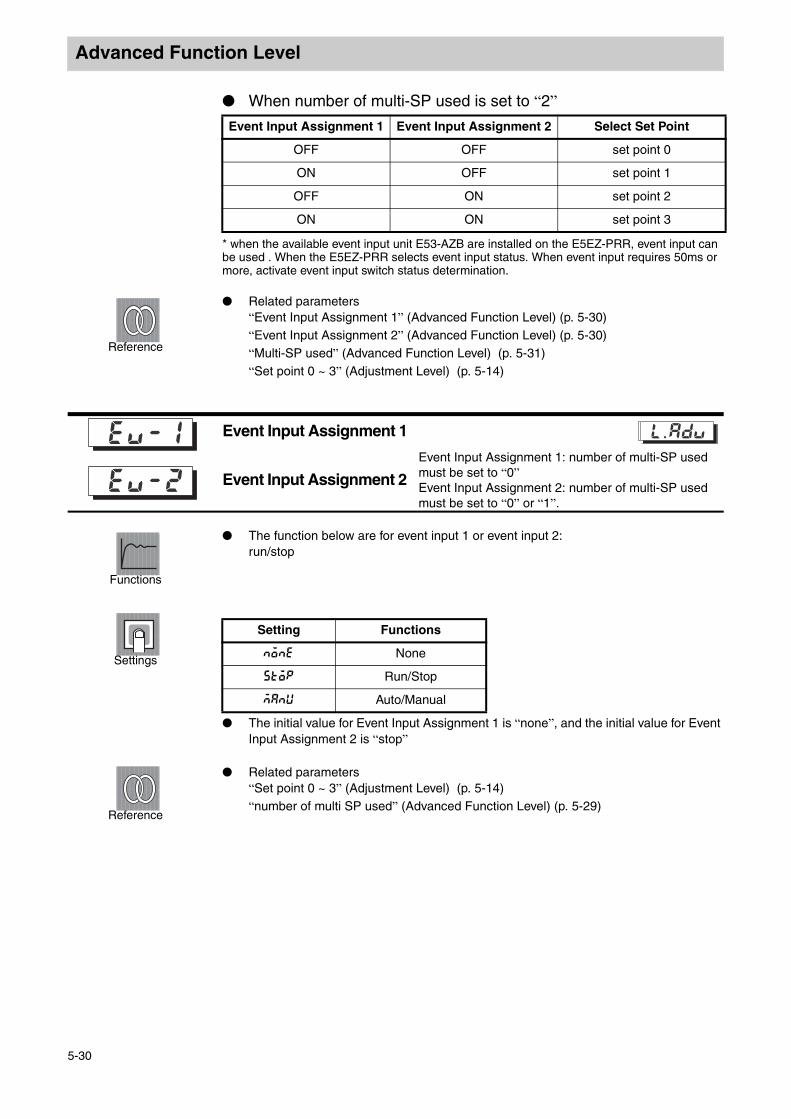
Advanced Function Level
When number of multi-SP used is set to “2”
* when the available event input unit E53-AZB are installed on the E5EZ-PRR, event input can be used . When the E5EZ-PRR selects event input status. When event input requires 50ms or more, activate event input switch status determination.
Reference
Related parameters“Event Input Assignment 1” (Advanced Function Level) (p. 5-30)“Event Input Assignment 2” (Advanced Function Level) (p. 5-30)“Multi-SP used” (Advanced Function Level) (p. 5-31)“Set point 0 ~ 3” (Adjustment Level) (p. 5-14)
Functions
The function below are for event input 1 or event input 2:run/stop
Settings
The initial value for Event Input Assignment 1 is “none”, and the initial value for Event Input Assignment 2 is “stop”
高级功能菜单
Reference
Related parameters“Set point 0 ~ 3” (Adjustment Level) (p. 5-14)“number of multi SP used” (Advanced Function Level) (p. 5-29)
Event Input Assignment 1 Event Input Assignment 2 Select Set Point
OFF OFF set point 0
ON OFF set point 1
OFF ON set point 2
ON ON set point 3
Event Input Assignment 1
Event Input Assignment 2 Event Input Assignment 1: number of multi-SP used must be set to “0”Event Input Assignment 2: number of multi-SP used must be set to “0” or “1”.
l.adj
Setting Functions
none None
stop Run/Stop
manu Auto/Manual
5-30

Advanced Function Level
Advanced Function Level
Functions
When the “multi-SP used” parameter is set to “ON”, setting values 0 ~ 3 may be set using the keys on the controller’s panel.
Settings
on : Users may select set point 0 ~ 3.off : Users may not select set point 0 ~ 3. initial value: off
Reference
Related parameters“multi-SP” (Operation Level ) (p. 5-8)“number of multi SP used” (Advanced Function Level) (p. 5-29)
Functions
This parameter is used to cancel the alarm standby sequence, select activate reset conditions.
When the “activate alarm1 on alarm” is set to “activate on alarm”, the heater burnout alarm and input error output also change to “activate on alarm”.
Condition A:control startup (including connecting power supply) , setting value, alarm value (upper and lower limit alarm value) or input shift value changed.
Condition B: Power ON The alarm type is shown below apply to the standby sequence lower limit alarm.
Settings
Reference
Related parameters “Alarm 1 ~ 2type”, “Alarm1~ 2 latch” (Advanced Function Level) (p. 5-36)
Number Of Multi SP Used The “number of multi-SP used” parameter must not
have installed event input units, or the “number of multi-SP used” parameter must be set to “0”.
l.adj
Standby Sequence Reset
alarm1 ~ 2 type must be set to “standby sequence”. l.adj
Alarm hysteresis
Alarm Point (after modification)
Alarm Point
Only Condition A
Only Condition A
Alarm Output: condition A
Alarm Output: condition B
SP modification
Standby Sequence Reset PointStandby Sequence Cancel Point
Setting Range Initial Value
a: condition A b: condition B a
5-31

Advanced Function Level
Functions
This parameter sets alarm1 output status. When the temperature controller is set to “shutdown on alarm”, alarm output function
status is always on. When set to “activate on alarm”, alarm output status will reverse or shut off. The following table describes the relationship between alarm output function and alarm output and output LCD indicator lights.
Settings
When “activate alarm1 on alarm” is set to “activate on alarm”, input error output also changes to “activate on alarm”.
Reference
Related parameters“Alarm value1” (p. 5-10) , “upper limit alarm value1”, “lower limit alarm value1” (p. 5-11) (Operation Level ) “Alarm 1 type ” (p. 5-24) ,“Alarm 1 hysteresis” (p. 5-32) , “Standby Sequence Reset”, “Alarm 1latch” (p. 5-31) (Advanced Function Level)
Functions
This parameter sets alarm output 1 hysteresis. With analog signal input, decimal point setting depends on the “decimal point”
setting.
Settings
Reference
Related parameters“alarm value1” (p. 5-10) , “upper limit alarm value1”, “lower limit alarm value1” (p. 5-11) (Operation Level ) “alarm 1 type ” (p. 5-24) , “Alarm 1 open in Alarm” (p. 5-32) , “Standby Sequence Reset” (p. 5-31) “Alarm1 latch (p. 5-36 ) ” (Advanced Function Level)
Alarm 1 Open in Alarm l.adj
Alarm Output operation
Alarm Output Output LCD
Close in AlarmON ON Lit
OFF OFF Not lit
Open in AlarmON OFF Lit
OFF ON Not lit
Setting Range Initial Value
n-o close in alarm/n-c open in alarm n-o
Alarm 1 Hysteresis “Alarm 1 type” parameter must not be “0”. l.adj
Setting Range Units Initial Value
Temperature Input 0.1 ~ 999.9 °C or °F 0.2
Analog Input 0.01 ~ 99.99 % FS 0.02
5-32
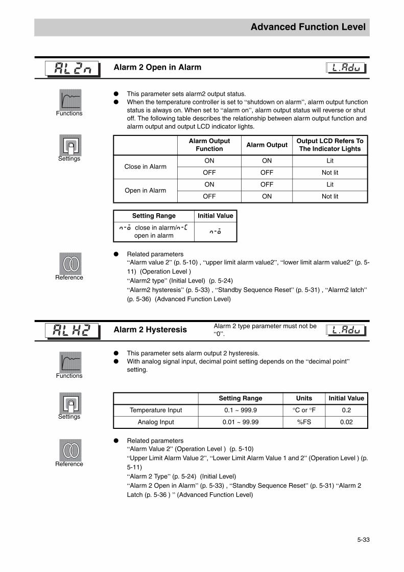
Advanced Function Level
Advanced Function Level
Functions
This parameter sets alarm2 output status. When the temperature controller is set to “shutdown on alarm”, alarm output function
status is always on. When set to “alarm on”, alarm output status will reverse or shut off. The following table describes the relationship between alarm output function and alarm output and output LCD indicator lights.
Settings
Reference
Related parameters“Alarm value 2” (p. 5-10) , “upper limit alarm value2”, “lower limit alarm value2” (p. 5-11) (Operation Level ) “Alarm2 type” (Initial Level) (p. 5-24)“Alarm2 hysteresis” (p. 5-33) , “Standby Sequence Reset” (p. 5-31) , “Alarm2 latch” (p. 5-36) (Advanced Function Level)
Functions
This parameter sets alarm output 2 hysteresis. With analog signal input, decimal point setting depends on the “decimal point”
setting.
Settings
Reference
Related parameters“Alarm Value 2” (Operation Level ) (p. 5-10) “Upper Limit Alarm Value 2”, “Lower Limit Alarm Value 1 and 2” (Operation Level ) (p. 5-11) “Alarm 2 Type” (p. 5-24) (Initial Level) “Alarm 2 Open in Alarm” (p. 5-33) , “Standby Sequence Reset” (p. 5-31) “Alarm 2 Latch (p. 5-36 ) ” (Advanced Function Level)
Alarm 2 Open in Alarm l.adj
Alarm Output Function
Alarm OutputOutput LCD Refers To The Indicator Lights
Close in AlarmON ON Lit
OFF OFF Not lit
Open in AlarmON OFF Lit
OFF ON Not lit
Setting Range Initial Value
n-o close in alarm/n-c open in alarm
n-o
Alarm 2 Hysteresis Alarm 2 type parameter must not be “0”. l.adj
Setting Range Units Initial Value
Temperature Input 0.1 ~ 999.9 °C or °F 0.2
Analog Input 0.01 ~ 99.99 %FS 0.02
5-33
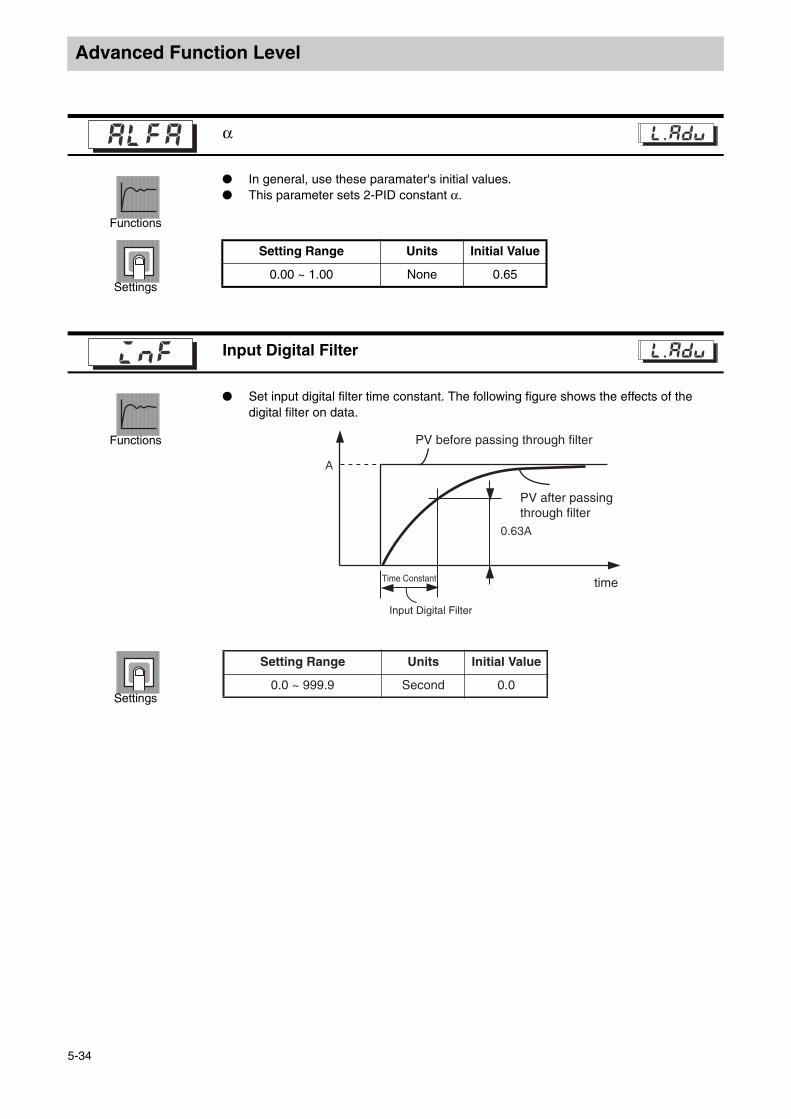
Advanced Function Level
Functions
In general, use these paramater's initial values. This parameter sets 2-PID constant α.
Settings
Functions
Set input digital filter time constant. The following figure shows the effects of the digital filter on data.
Settings
α l.adj
Setting Range Units Initial Value
0.00 ~ 1.00 None 0.65
Input Digital Filter l.adj
timeTime Constant
Input Digital Filter
PV before passing through filter
PV after passing through filter
Setting Range Units Initial Value
0.0 ~ 999.9 Second 0.0
5-34

Advanced Function Level
Advanced Function Level
Functions
Add process value display at the beginning of Operation Level. If you do not want the set point/valve open percentage to display, only use when displaying current temperature.
Settings
Functions
In the “Operation Level ” and “Adjustment Level”, if the panel setting keys are not used for a period of time, then the display will automatically return to the PV/SP/MV. When this parameter is set to “OFF”, this function is not effective (display cannot change automatically) .
Settings
Additional Process Value Display l.adj
Setting Range Initial Value
on:display/off not displayed off
Automatic Display Return Time l.adj
Setting Range Units Initial Value
OFF, 1~99 Second off
5-35
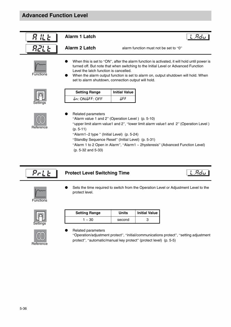
Advanced Function Level
Functions
When this is set to “ON”, after the alarm function is activated, it will hold until power is turned off. But note that when switching to the Initial Level or Advanced Function Level the latch function is cancelled.
When the alarm output function is set to alarm on, output shutdown will hold. When set to alarm shutdown, connection output will hold.
Settings
Reference
Related parameters“Alarm value 1 and 2” (Operation Level ) (p. 5-10) “upper limit alarm value1 and 2”, “lower limit alarm value1 and 2” (Operation Level ) (p. 5-11) “Alarm1~2 type ” (Initial Level) (p. 5-24) “Standby Sequence Reset” (Initial Level) (p. 5-31) “Alarm 1 to 2 Open in Alarm”, “Alarm1 ~ 2hysteresis” (Advanced Function Level) (p. 5-32 and 5-33)
Functions
Sets the time required to switch from the Operation Level or Adjustment Level to the protect level.
Settings
Reference
Related parameters“Operation/adjustment protect”, “initial/communications protect”, “setting adjustment protect”, “automatic/manual key protect” (protect level) (p. 5-5)
Alarm 1 Latch
Alarm 2 Latch alarm function must not be set to “0”
l.adj
Setting Range Initial Value
on: ON/off: OFF off
Protect Level Switching Time l.adj
Setting Range Units Initial Value
1 ~ 30 second 3
5-36

Advanced Function Level
Advanced Function Level
Settings
When this is set to “ON”, alarm1 output changes to “ON” when input errors occur. But note that alarm 1 operation display will not come on.
When switching to the Initial Level, Communications Level, Advanced Function Level, output will shutdown.
Settings
Reference
Related parameters“input error ” (error display) (A-4)
Functions
When input type setting value is set to 5 ~ 20, 22 or 23, determination is made by internal or external controller cold junction compensation.
When using two thermocouples or two ES1B to measure temperature differences, external cold junction compensation settings are effective.
Settings
Reference
Related parameters“input error” (error display) (A-4)
Input Error Output l.adj
Setting Range Initial Value
on: Enabled/off: Disabled off
Cold Junction Compensation Method
Input type must be thermocouple or non-contact temperature sensor.
l.adj
Setting Range Initial Value
on: internal off: external on
5-37

Advanced Function Level
Functions
Sysway communications procedure, switch MB command logic (communications writing switching)
MB command (communications writing switching) and E5 J MB command (remote/local switching) are equivalent.
The shaded area indicates the settings initial values (same logic as E5 J).
Settings
(includes the explanation of the symbols used in the E5 J) .
Reference
Related parameters“communications writing” (Adjustment Level) (p. 5-13)
This parameter is used to set alarm1, 2, 3 output delay time. Output activation and shutdown delay can be set separately.
Alarm type must be set to something other than 0 type Related parameters
“alarm 1 ~ 2 type ” (Initial Level) (p. 5-24)
MB Command Logic Switching
communications function accords to model l.adj
Setting Value
MB Command Version Data
0000 0001
OFFcommunications writing activation (select remote mode)
communications writing deactivation (select local mode)
ON communications writing deactivation (select local mode)
communications writing activation (select remote mode)
Alarm 1 ON delay
Alarm 2 ON delay
Alarm 1 OFF delay Alarm1, 2 type is not “0: no alarm function”
Alarm 2 OFF delay
a1on l.adj
a2on
Setting Range Units Initial Value
0 ~ 99 Second 0
5-38
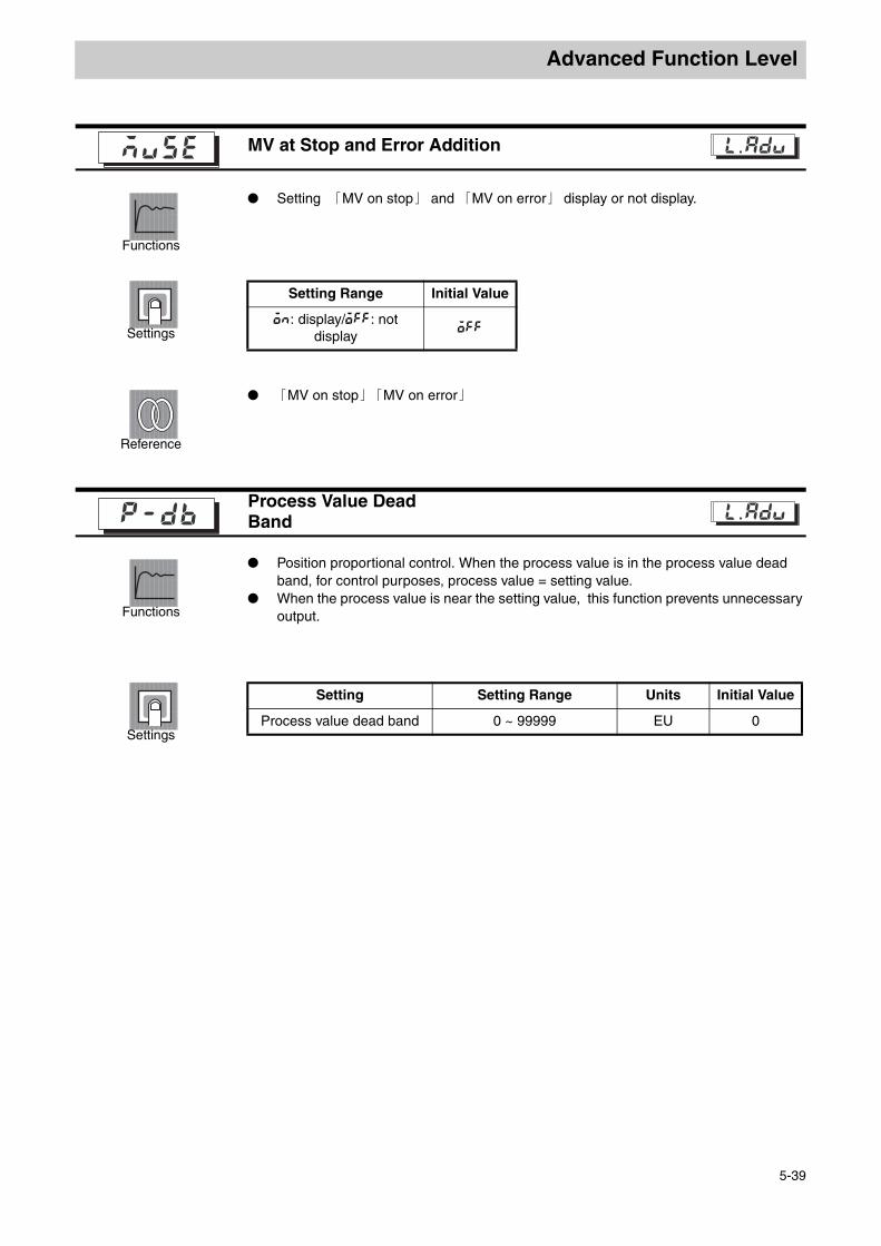
Advanced Function Level
Advanced Function Level
Functions
Setting 「MV on stop」 and 「MV on error」 display or not display.
Settings
Reference
「MV on stop」「MV on error」
Functions
Position proportional control. When the process value is in the process value dead band, for control purposes, process value = setting value.
When the process value is near the setting value, this function prevents unnecessary output.
Settings
MV at Stop and Error Addition l.adj
Setting Range Initial Value
on: display/off: not display
off
Process Value Dead Bandp-db l.adj
Setting Setting Range Units Initial Value
Process value dead band 0 ~ 99999 EU 0
5-39

Advanced Function Level
Functions
Displays valve open percentage, used when valve open percentage is not displayed.
Settings
Functions
Sets effectiveness of manual MV limit.(during floating control, this setting value is not effective)
Settings
Valve Opening Display l.adj
Setting Range Initial Value
on: display/off: not display
on
Manual MV Limit Effectiveness
Only closed controlmanl l.adj
Setting Range Initial Value
on: effective/off: not effective on
5-40

Communications Level
Communications LevelSetting communications specifications level.Can only be displayed by models with communications function.
Communications Level
Press the key to change between setting levels. Press the UD key to change setting values.
25
100
100
c
Input Power Supply
Operation Level Adjustment Level
Press key less than 1 sec.
Press key more than 1 sec.
Press key more than 3 sec.
key No. 1 display
Control Stop
Initial setting levelPress key less than 1 sec.
Communications Level
Control in progress
Control stopped
M
u-no
1
M
M
7
M
bps
len
sbit
96.
2
prty
5-42
5-42
5-42
5-42
5-42
l.com
l.com
l.com
l.com
l.com
Initial setting level
Communication Unit No
Page No.
Baud Rate
Data Length
Stop Bit
Communication Parity
5-41

Communications Level
Communications Level
Functions
When power is reset, all parameters are activated. Match the communications used on the E5EZ-PRR201 / PRR203and the host. If
using one to many connections, ensure that the system has uniform communications protocols (unless “communications unit code” is selected).
Settings
Reference
Related parameters“communications writing” (Adjustment Level) (p. 5-13)
Communications Unit Code
Communications function accords to model.
Baud Rate
Data Length
Stop Bit
Communication Parity
l.adjcom
ParameterDisplay
SymbolsSetting Value
Initial Value
Setting Range
Communications Unit Code
u-no 0,1 99~ 1 0-99
Baud Rate bps 1. 2/2. 4/4. 8/9. 6/19.. 2 9. 6
1.2/2.4/4.8/ 9.6/19.2 (kb/s)
Data Length len 7 8/ 7 7/8 (bit)
Stop Bit sbit 1 2/ 2 1/2
Communication Parity
prty none even odd/ / evenNone/even/odd
5-42

Appendix
AAppendix
Specifications ......................................................................................... A-2Ratings........................................................................................ A-2Characteristics ............................................................................ A-3
Error Display........................................................................................... A-4Parameter operations table .................................................................... A-6Sensor input settings and indicator range ............................................ A-10Setting Data List ................................................................................... A-11Parameter Flow .................................................................................... A-12
A-1
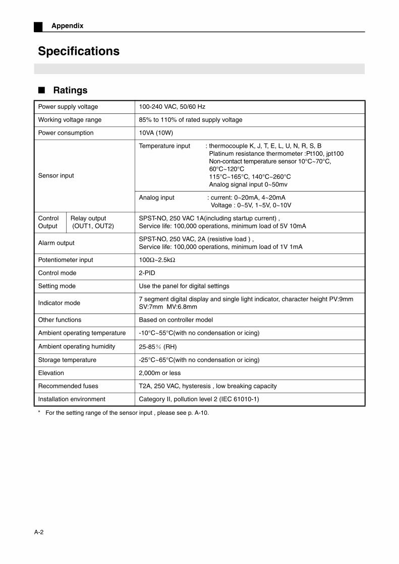
Appendix
Specifications
Ratings
* For the setting range of the sensor input , please see p. A-10.
Power supply voltage 100-240 VAC, 50/60 Hz
Working voltage range 85% to 110% of rated supply voltage
Power consumption 10VA (10W)
Sensor input
Temperature input : thermocouple K, J, T, E, L, U, N, R, S, B Platinum resistance thermometer :Pt100, jpt100 Non-contact temperature sensor 10°C~70°C,
60°C~120°C 115°C~165°C, 140°C~260°C Analog signal input 0~50mv
Analog input : current: 0~20mA, 4~20mA Voltage : 0~5V, 1~5V, 0~10V
Control Output
Relay output (OUT1, OUT2)
SPST-NO, 250 VAC 1A(including startup current) , Service life: 100,000 operations, minimum load of 5V 10mA
Alarm outputSPST-NO, 250 VAC, 2A (resistive load ) ,Service life: 100,000 operations, minimum load of 1V 1mA
Potentiometer input 100Ω~2.5kΩ
Control mode 2-PID
Setting mode Use the panel for digital settings
Indicator mode7 segment digital display and single light indicator, character height PV:9mm SV:7mm MV:6.8mm
Other functions Based on controller model
Ambient operating temperature -10°C~55°C(with no condensation or icing)
Ambient operating humidity 25-85% (RH)
Storage temperature -25°C~65°C(with no condensation or icing)
Elevation 2,000m or less
Recommended fuses T2A, 250 VAC, hysteresis , low breaking capacity
Installation environment Category II, pollution level 2 (IEC 61010-1)
A-2
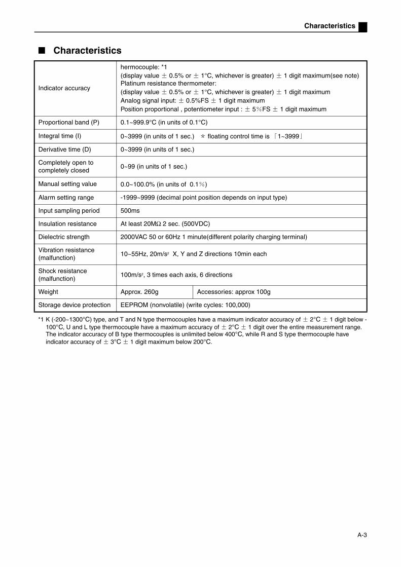
Characteristics
Characteristics
*1 K (-200~1300°C) type, and T and N type thermocouples have a maximum indicator accuracy of ± 2°C ± 1 digit below -100°C, U and L type thermocouple have a maximum accuracy of ± 2°C ± 1 digit over the entire measurement range. The indicator accuracy of B type thermocouples is unlimited below 400°C, while R and S type thermocouple have indicator accuracy of ± 3°C ± 1 digit maximum below 200°C.
Indicator accuracy
hermocouple: *1(display value ± 0.5% or ± 1°C, whichever is greater) ± 1 digit maximum(see note)Platinum resistance thermometer:(display value ± 0.5% or ± 1°C, whichever is greater) ± 1 digit maximumAnalog signal input: ± 0.5%FS ± 1 digit maximumPosition proportional , potentiometer input : ± 5%FS ± 1 digit maximum
Proportional band (P) 0.1~999.9°C (in units of 0.1°C)
Integral time (I) 0~3999 (in units of 1 sec.) * floating control time is 「1~3999」
Derivative time (D) 0~3999 (in units of 1 sec.)
Completely open to completely closed
0~99 (in units of 1 sec.)
Manual setting value 0.0~100.0% (in units of 0.1%)
Alarm setting range -1999~9999 (decimal point position depends on input type)
Input sampling period 500ms
Insulation resistance At least 20MΩ 2 sec. (500VDC)
Dielectric strength 2000VAC 50 or 60Hz 1 minute(different polarity charging terminal)
Vibration resistance (malfunction)
10~55Hz, 20m/s2 X, Y and Z directions 10min each
Shock resistance (malfunction)
100m/s2, 3 times each axis, 6 directions
Weight Approx. 260g Accessories: approx 100g
Storage device protection EEPROM (nonvolatile) (write cycles: 100,000)
A-3

Appendix
Error Display
When errors occur, the main display will alternately display the error code and the current display.This section explains how to find error codes and corrective procedures.
Meaning Input value exceeds input indicator range (input indicator range is -1999(-199.9) ~ 9999(999.9) ) .
Corrective measures
Check input wiring for miswiring, disconnections, short circuits, and input type.If there are problems with the wiring or input type, shut off the power supply then turn it back on. If the display does not change, then the E5EZ-PRR must be replaced. If the display returns, , then the system might have been affected by electrical noise. check electrical noise.
Actions on error Control output will output MV based on the “MV during error” setting position.Alarm output function is the same as when the upper limit is exceeded.When “output input error” (advanced function level ) is set to ON, alarm 1 output will activate when an error occurs.When “process value” or “process value/setting value/valve open percentage” is displayed, error information will be displayed.
Meaning Even though this is not an error, when the control range exceeds the display range (-1999(-199.9) ~ 9999(999.9) ) , or the process value exceeds the display range, this will be displayed .
Displays when smaller than “-1999 (-199.9) ” Displays when more than “9999 (999.9) ”
Actions on error Control continues, operates normally. When “process value” or “process value/setting value/valve open percentage” is displayed, error information will be displayed.
Input error
Exceed display range
A-4

Characteristics
Meaning Internal storage device error.
Corrective measures
First, disconnect and then reconnect the power supply. If the display does not change, then the E5EZ-PRR must be replaced. If the display returns, , then the system might have been affected by electrical noise. Check for electrical noise.
Actions on error Control output and alarm output off.
Meaning A potentiometer input error occurred.Valve opening outside the -10% ~ 110% range.
Corrective measures
Ensure that there are no wiring problems with the potentiometer, broken wires, or short circuits.If there are no wiring errors then the power supply can be turned on, and if the display content has not changed it will need to be replaced. If normal operation resumes then external interference might have been the cause, and should be avoided.
Actions on error Control output will output MV based on the “MV during error” setting position.Alarm output normal operation.
Meaning Electro-mechanical calibration did not completely finish.
Corrective measures
Ensure that the potentiometer and valve drive motor were calibrated after they were wired.
Actions on error Control output, alarm output set to OFF.
Storage device error
•
platinum resistance thermometer input(setting range does not include -199.9-500.0 (˚C) type)thermocouple input(setting range does not include -199.9-400.0 (˚C) type)
S.Err indicator S.Err indicatornumeric value display input indicator range
display range
numeric value display
input indicator range
display range
S.Err indicatornumeric value display input indicator range
display range
numeric value display input indicator range
display range
platinum resistance thermometer input(setting range does not include -199.9-500.0 (˚C) type)thermocouple input(setting range does not include -199.9-400.0 (˚C) type)
S.Err indicatorcccc indicator
S.Err indicator S.Err indicator
S.Err indicator
cccc indicator cccc indicator
•
Analog signal input
Analog signal input
display range < numeric value display
display range > numeric value display
Potentiometer input error----
Electro-mechanical calibration error
A-5

Appendix
Parameter operations table
Manual control level
Operation level
Adjustment level
Parameter name Symbol Setting (monitor) value DisplayInitial value
UnitsSetting value
Manual MV — -10~110.0 — %
Parameter name Symbol Setting (monitor) value DisplayInitial value
UnitsSetting value
Process value Sensor input indicator range EU
Present value/set value/valve open percentage
SP lower limit ~ SP upper limit
0 EU
Multi-SP m-sp 0~3 0 None
SP ramp set points sp-m SP lower limit ~ SP upper limit
EU
Run/stop r-s Run, stop run, stop Run None
Alarm value 1 al-1 -1999~9999 0 EU
Upper limit alarm value 1 al 1h -1999~9999 0 EU
Lower limit alarm value 1 al 1l -1999~9999 0 EU
Alarm value 2 al-2 -1999~9999 0 EU
Upper limit alarm value 2 al 2h -1999~9999 0 EU
Lower limit alarm value 2 al 2l -1999~9999 0 EU
Parameter name Symbol Setting (monitor) value DisplayInitial value
UnitsSetting value
Run/stop AT at ON, OFF on, off off None
Communications writing cmwt ON, OFF on, off off None
Set point 0 sp-0 SP lower limit ~ SP upper limit 0 EU
Set point 1 sp-1 SP lower limit ~ SP upper limit 0 EU
Set point 2 sp-2 SP lower limit ~ SP upper limit 0 EU
Set point 3 sp-3 SP lower limit ~ SP upper limit 0 EU
Temperature input shift ins -199.9~999.9 0.0 °C or °FUpper limit temperature input shift value
insh -199.9~999.9 0.0 °C or °F
Lower limit temperature input shift value
insl -199.9~999.9 0.0 °C or °F
Proportional band p Temperature input: 0.1~999.9 8.0 EU
Analog input:0.1~999.9 10.0 %FS
Integral time i Floating: 1~3999 233 Second
Closed: 0~3999
Derivative time d 0~3999 40 Second
MV when stopped iv-s Closed, hold, open clos, hold, opev Hold None
MV during error iv-e Closed, hold, open clos, hold, opev Hold None
SP ramp set point sprt OFF、 1~9999 off, 1~9999 OFF EU
MV limit upper limit value ol-h MV limit lower limit value +0.1~105.0
100.0 %
MV limit upper limit value ol-l -5.0~MV limit upper limit value -0.1
0.0 %
Position proportional dead band
db Floating: 0.1~10.0 2.0 %
Closed:0.1~10.0 4.0 %
Hysteresis off/on oc-h 0.1~20.0 0.8 %
A-6

Parameter operations table
Initial level
Parameter name Symbol Setting (monitor) value Display Initial value
UnitsSetting value
Initial setting
Input type in-t Input temperature
0: Pt100 (-200~850°C/-300~1500F) 1: Pt100 (-199.9°C~500.0°C/-199.9~900.0F)2: Pt100 (0.0~100.0°C/0.0~210.0F) 3: JPt100 (-199.9°C~500.0°C/-199.9~900.0F)4: JPt100 (0.0~100.0°C/0.0~210.0F) 5: K (-200~1300°C/-300~2300F) 6: K (-20.0~500.0°C/0.0~900.0F) 7: J (-100~850°C/-100~1500F) 8: J (-20.0~400.0°C/0.0~750F) 9: T (-200~400°C/-300~700F) 10: E (0~600°C/0~1100F) 11: L (-100~850°C/-100~1500F) 12: U (-200~400°C/-300~700F) 13: N (-200~1300°C/-300~2300F) 14: R (0~1700°C/0~3000F) 15: S (0~1700°C/0~3000F) 16: B (100~1800°C./300~3200F) 17: 10~70°C(0~90°C/0~190F) 18: 60~120°C(0~120°C/0~240F) 19: 115~165°C(0~165°C/0~320F) 20: 160~260°C(0~260°C/0~500F) 21: 0~50mV 22: T(-199~400.0°C/-199~700F) 23: U(-199~400.0°C/-199~700F)
5 None
Analog input
0 :4~20mA 1 :0~20mA 2 :1~5V 3 :0~5V 4 :0~10V
0 None
Scaling upper limit
in-h Scaling lower limit +1~9999 100 None
Scaling lower limit
in-l -1999~scaling upper limit -1 0 None
Decimal point
dp Temperature input: 0~1 0 None
Analog input: 0~3 0 None
Select °C/°F
d-u °C, °F c, f °C None
Set point upper limit
sl-h SP lower limit +1 through input range lower limit (temperature )
1300 EU
SP lower limit +1 through scaling upper limit(analog signal) 100 EU
Set point lower limit
sl-l Input range lower limit through SPupper limit-1(temperature )
-200 EU
Scaling lower limit through SPupper limit-1(analog signal ) 0 EU
Direct / reverse operation
orev Direct operation, reverse operation or-d,or-r Reverse operation
None
Alarm 1 type
alt1 0: turn off alarm function 1: upper limit and lower limit alarm 2: upper limit alarm 3: lower limit alarm 4: upper and lower limit range 5: attached standby sequence upper and lower limit alarm 6: attached standby sequence upper limit alarm 7: attached standby sequence lower limit alarm 8: absolute value upper limit alarm 9: attached absolute value lower limit alarm 10: attached standby sequence absolute value upper limit alarm 11: standby sequence absolute value lower limit alarm
2 None
Alarm 2 type
alt2 Alarm 1 type 2 Second
Closed/floating
clfl Closed, floating flot, clos Floating None
Electro-mechanical calibration
calb ON, OFF on, off OFF None
Travel time mot 1~999 30 Second
Switch to advanced function level
amov -1999~9999 0 None
A-7

Appendix
Advanced function level
Protect level
Parameter name Symbol Setting (monitor) value DisplayInitial value
UnitsSetting value
Parameter initialization init ON, OFF on off OFF None
Number of multi-SP used ev-m 0~2 1 None
Event input indicator 1 ev-1 Event input 1, run/stop, automatic /manual
none, stop, mavu None None
Event input indicator 2 ev-2 Event input 1, run/stop, automatic /manual
none, stop, mavu RUN/STOP
None
Number of multi-SP used mspu ON, OFF on off OFF None
Standby sequence reset rest Condition A, condition B a b Condition A
None
Activate on alarm1 on alarm al1n Activate on alarm /shutdown on alarm
n-o n-c Activate on alarm
None
Alarm 1 hysteresis alh1 Temperature input1: 0.1~999.9 0.2 EU
Analog input: 0.01~99.99 0.02 %FS
Activate on alarm2 on alarm al2n Activate on alarm / shutdown on alarm
n-o n-c Activate on alarm
None
Alarm2 hysteresis alh2Temperature input 1:0.1~999.9 0.2 EU
Analog input: 0.01~99.99 0.02 %FS
α alfa 0.00~1.00 0.65 None
Input digital filter inf 0.1~999.9 0.0 Second
Additional process value display
pvad ON, OFF on off OFF None
Display mode automatic return
ret OFF, 1~9999 off 1~9999 OFF Second
Alarm1 latch a1lt ON, OFF on off OFF None
Alarm2 latch a2lt ON, OFF on off OFF None
Protect level switching time prlt 1~30 on off 3 Second
Output input error sero ON, OFF on off OFF None
Cold junction compensation method
cjc ON, OFF on off ON None
MB command logic switching rlrv ON, OFF on off OFF None
Alarm1 on delay a1on 0~99 0 Second
Alarm2 ON delay a2on 0~99 0 Second
Alarm1 OFF delay a1of 0~99 0 Second
Alarm2 OFF delay a2of 0~99 0 Second
When stop/error add MV mvse ON, OFF on off OFF None
Process value dead band p-db 0~9999 0 EU
Valve open display v-dp ON, OFF on off ON None
Manual MV limit is effective manl ON, OFF on off ON None
Parameter name Symbol Setting (monitor) value DisplayInitial value
UnitsSetting value
Operation/adjustment protect oapt 0~3 0 None
Initial/communication protect icpt 0~2 1 None
Setting change protect wtpt ON, OFF on off OFF None
Manual /automatic key protection keyp ON, OFF on off OFF None
A-8

Characteristics
Communications level
Parameter name Symbol Setting (monitor) value DisplayInitial value
UnitsSetting value
Communications unit code u-no 0~99 1 None
Baud rate bps 1.2, 2.4, 4.8, 9.6, 19.2 1.2,2. 4,4. .8,9. 6,19. 2
9.6 Kbps
Data length len 7, 8 7 Bit
Stop bit sbit 1, 2 2 Bit
Communication parity prty None, even, odd none even odd Even None
A-9

Appendix
Sensor input settings and indicator range
E5EZ-PRR2 T
E5EZ-PRR2 L
• Thermocouple/multi input type platinum resistance thermometer initial value is 「5」 , analog input type is 「0」 .• Input type specifications are given below:
Control range• Platinum resistance thermometer and thermocouple input temperature setting lower limit -20°C~ temperature upper limit+20°C or
temperature setting lower limit -40F~ temperature setting upper limit+40F.• ES1B input type has the same input indicator range.• Analog input indicator range -5%~105%.
Input type SpecificationsSetting value
Input temperature range Input indicator range
Thermocouple/multi input type platinum resistance thermometer
Platinum resistance thermometer
Pt100 0 -200~850 (°C) /-300~1500 (°F) -200~870 (°C) /-340~1540 (°F)
1 -199.9~500.0 (°C) /-199.9~900.0 (°F)
-199.9~520.0 (°C) /-199.9~940.0 (°F)
2 0.0~100.0 (°C) /0.0~210.0 (°F) -20.0~120.0 (°C) /-40.0~250.0 (°F)
JPt100 3 -199.9~500.0 (°C) /-199.9~900.0 (°F)
-199.9~520.0 (°C) /-199.9~940.0 (°F)
4 0.0~100.0 (°C) /0.0~210.0 (°F) -20.0~120.0 (°C) /-40.0~250.0 (°F)
Thermocouple
K 5 -200~1300 (°C) /-300~2300 (°F) -220~1320 (°C) /-340~2340 (°F)
6 -20.0~500.0 (°C) /0.0~900.0 (°F) -40.0~520.0 (°C) /-40.0~940.0 (°F)
J 7 -100~850 (°C) /-100~1500 (°F) -120~870 (°C) /-140~1540 (°F)
8 -20.0~400.0 (°C) /0.0~750.0 (°F) -40.0~420.0 (°C) /-40.0~790.0 (°F)
T 9 -200~400 (°C) /-300~700 (°F) -220~420 (°C) /-340~740 (°F)
22 -199.9~400.0 (°C) /-199.9~700.0 (°F)
-199.9~420.0 (°C) /-199.9~740.0 (°F)
E 10 0~600 (°C) /0~1100 (°F) -20~620 (°C) /-40~1140 (°F)
L 11 -100~850 (°C) /-100~1500 (°F) -120~870 (°C) /-140~1540 (°F)
U 12 -200~400.0 (°C) /-300~700 (°F) -220~420 (°C) /-340~740 (°F)
23 -199.9~400.0 (°C) /-199.9~700.0 (°F)
-199.9~420.0 (°C) /-199.9~740.0 (°F)
N 13 -200~1300 (°C) /-300~2300 (°F) -220~1320 (°C) /-340~2340 (°F)
R 14 0~1700 (°C) /0~3000 (°F) -20~1720 (°C) /-40~3040 (°F)
S 15 0~1700 (°C) /0~3000 (°F) -20~1720 (°C) /-40~3040 (°F)
B 16 100~1800 (°C) /300~3200 (°F) 0~1820 (°C) /0~3240 (°F)
Non-contact temperature sensor ES1B
10°C-70°C 17 0~90 (°C) /0~190 (°F) -20~130 (°C) /-40~270 (°F)
60°C-120°C 18 0~120 (°C) /0~240 (°F) -20~160 (°C) /-40~320 (°F)
115°C-165°C 19 0~165 (°C) /0~320 (°F) -20~205 (°C) /-40~400 (°F)
140°C-260°C 20 0~260 (°C) /0~500 (°F) -20~300 (°C) /-40~580 (°F)
Analog signal input
0~50mV 21 One of the ranges below, depending on the displayed results: -1999~9999, -199.9~999.9
-5 ~ 105% of the setting range (however, display -1999 ~ 9999 or -199.9 ~ 999.9)
Analog Input type CurrentInput
4~20mA 0 -5 ~ 105% of the setting range (however, display -1999 ~ 9999 or -199.9 ~ 999.9) Other than the decimal point's numerical value range .
0~20mA 1 -1999~9999
VoltageInput
1~5V 2 -199.9~999.9
0~5V 3 -19.99~99.99
0~10V 4 -1.999~9.999
K: GB/T 2814-98 J, L: GB/T 4994-98 T, U: GB/T 2903-98
E: GB/T 4993-98 N: GB/T 17615-98 R : GB/T 1598-98
S: GB/T 3772-98 B: GB/T 2902-99 JPt100, Pt100:GB/T5977-99
A-10

Characteristics
Setting Data List
The following chart gives an overview of the setting levels on the E5EZ-PRR.To switch to the advanced function level, you must input the password. Certain parameters will not be displayed, based on protect level settings and usage conditions.When switching from the operation level to the initial level, control stops.
25
100
c
25
100
c
L
L
L
L
L
L
1
2
2 1
M
+M
+
2
100.0
100.0
+
M
Input Power SupplyManual Operation Auto Operation
Press A key one more than 1 second
Operation Level Adjustment Level
Press the key less than 1second
key
Presskey one more than 3 second
Press A key one more than 1 second Press
key one more than 1 second
LPress key one more than 3 second
After press key more than 1 second, PV displays blink
key
LPress key one more than 1 second
L
Press the key less than 1second
Manual Control Level Initial Setting Level communications setting level Protect Level
Input password set value “-169”
Advanced Function Setting Level
Control in progress
Control stops
Unable to display depend on modles
Level change
From initial level to operation level shows default measure of the operation
level. From initial level and manual control level to operation level shows default measure of the operation level.
Key-pressing time could be changed in “protect level turning time” (advanced function setting level)
Control Stops
PV display will blink
A-11
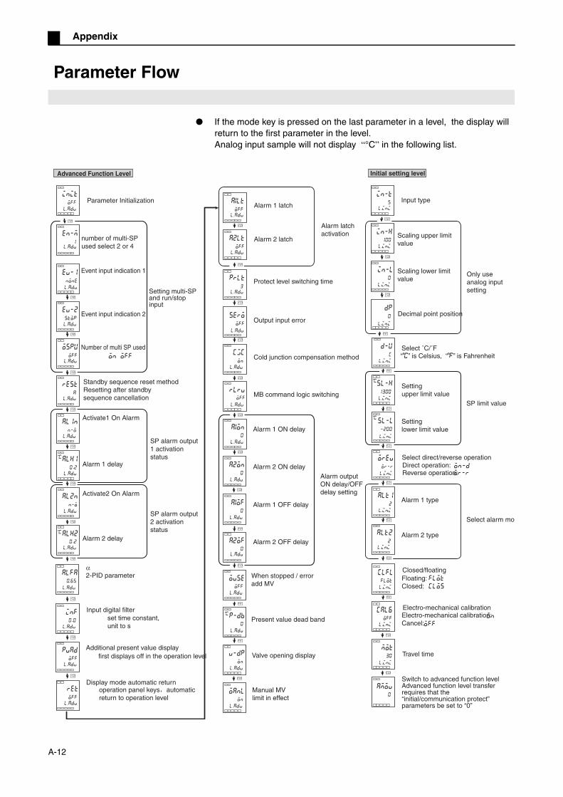
Appendix
Parameter Flow
If the mode key is pressed on the last parameter in a level, the display will return to the first parameter in the level.Analog input sample will not display “°C” in the following list.
init
off
en-m
1
none
stop
ospu
off
rest
a
al1n
n-o
on off
al2n
n-o
alh1
0 2
alh2
0 2
C
C
a1lt
off
a2lt
off
a2of
0
in-t
5
l.ini
in-l
0
in-h
100
dp
0
l.
l.
l.
prlt
3
cjc
on
sero
off
a1on
0
off
a2on
0
a1of
0
l.
l.
l.
l.
l.
l.
l.
on
oanl
on
p-db
0
l.
l.
l.
alfa
0.65
l.
l.
l.
l.
l.
l.
l.
l.
l.
l.
l.
l.
off
l.ini
l.ini
l.ini
d-u
c
sl-h
1300
sl-l
-200
on-d
or-r
alt2
2
flot
clos
on
off
alt1
2
clfl
flot
cal6
off
mot
30
l.ini
l.ini
l.ini
l.ini
l.ini
l.ini
l.ini
l.ini
l.ini
0
α
off
inf
0 0
l.
l.
ret
off
l.
C
C
C
Advanced Function Level
Parameter Initialization
number of multi-SP used select 2 or 4
Event input indication 1
Event input indication 2
Number of multi SP used
Standby sequence reset methodResetting after standby sequence cancellation
Activate1 On Alarm
Activate2 On Alarm
Alarm 1 delay
Alarm 2 delay
SP alarm output 1 activation status
SP alarm output 2 activation status
2-PID parameter
Input digital filterset time constant, unit to s
Additional present value displayfirst displays off in the operation level
Display mode automatic returnoperation panel keys automatic return to operation level
Alarm 1 latch
Alarm 2 latch
Protect level switching time
Output input error
Cold junction compensation method
MB command logic switching
Alarm 1 ON delay
Alarm 2 ON delay
Alarm 1 OFF delay
Alarm 2 OFF delay
When stopped / erroradd MV
Present value dead band
Valve opening display
Manual MVlimit in effect
Alarm output ON delay/OFF delay setting
Alarm latch activation
Initial setting level
Input type
Scaling upper limit value
Scaling lower limit value
Decimal point position
Select ˚C/˚F“C” is Celsius, “F” is Fahrenheit
Only use analog input setting
Setting upper limit value
Setting lower limit value
Select direct/reverse operationDirect operation:Reverse operation:
Alarm 1 type
Alarm 2 type
Closed/floatingFloating:Closed:
Electro-mechanical calibrationElectro-mechanical calibration:Cancel:
Travel time
Switch to advanced function levelAdvanced function level transfer requires that the “initial/communication protect” parameters be set to “0”
SP limit value
Select alarm mod
Setting multi-SP and run/stop input
A-12
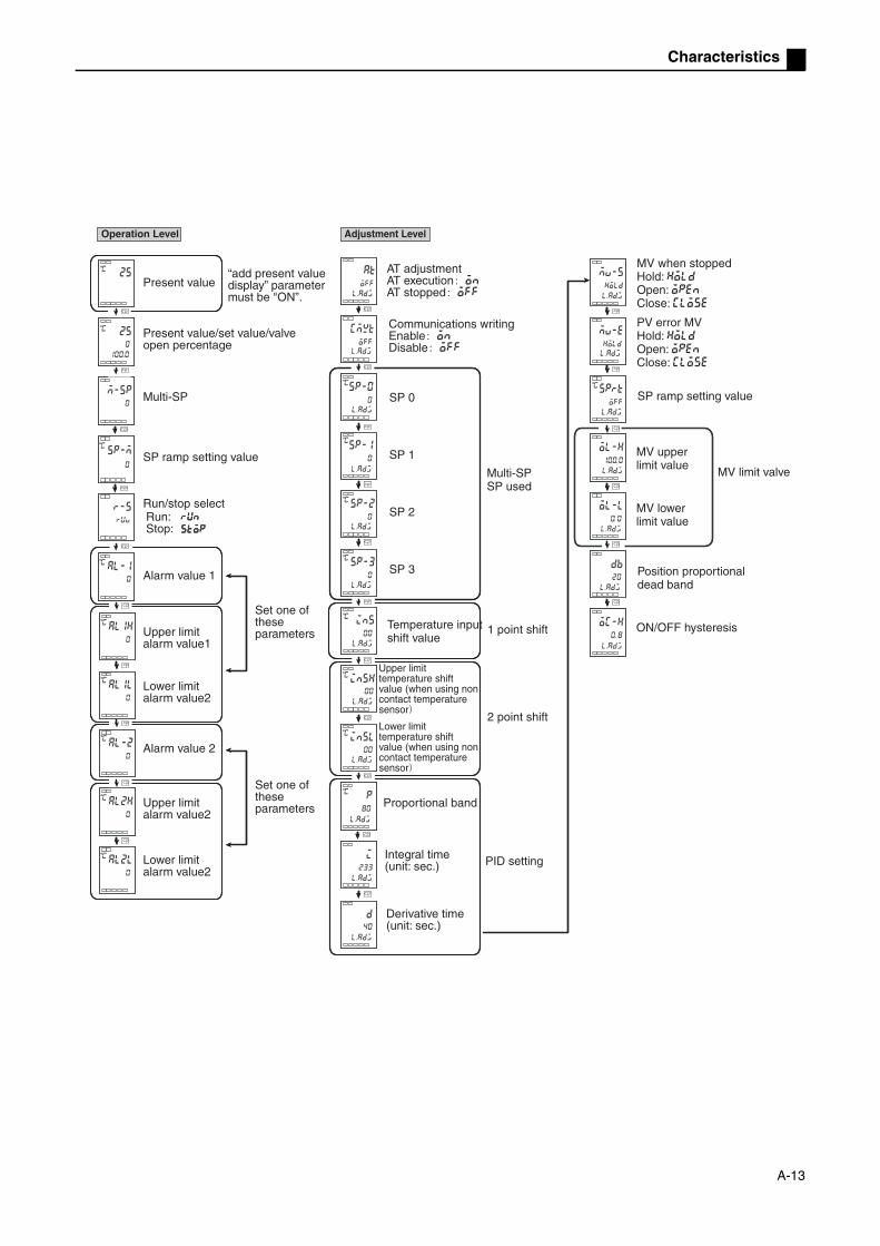
Characteristics
sprt
off
ol-h
ol-l
oc-h
db
20
0. 8
at
off
l.adj l.adj
l.adj
l.adj
l.adj
l.adj
l.adj
l.adj
cmwt
off
sp-0
0
sp-1
0
sp-2
0
in5
00
sp-3
0
in5l
00
in5h
00
p
80
d
40
i
233
al1h
0
al1l
0
al-2
0
al2h
0
al2l
0
25
m-sp
0
sp-m
0
run
stop
al-1
0
25
0
0100.l.adj
l.adj
l.adj
l.adj
l.adj
l.adj
l.adj
l.adj
l.adj
l.adj
l.adj
100. 0
0. 0
C
C
C C
C
C
C
C
C
C
C
C
C
C
C
C
C
C
Adjustment LevelOperation Level
Present value
Present value/set value/valve open percentage
“add present value display” parameter must be "ON”.
Multi-SP
SP ramp setting value
Run/stop selectRun:Stop:
Alarm value 1
Upper limit alarm value1
Lower limit alarm value2
Alarm value 2
Lower limit alarm value2
Upper limit alarm value2
Set one of these parameters
Set one of these parameters
AT adjustmentAT execution onAT stopped off
Communications writingEnable onDisable off
SP 0
SP 1
SP 2
SP 3
Multi-SPSP used
Temperature input shift value
1 point shift
2 point shift
Upper limit temperature shift value (when using non contact temperature sensor
Lower limit temperature shift value (when using non contact temperature sensor
Proportional band
Integral time(unit: sec.)
Derivative time(unit: sec.)
PID setting
MV when stoppedHold: holdOpen: openClose: close
PV error MVHold: holdOpen: openClose: close
SP ramp setting value
MV upper limit value
MV lower limit value
Position proportional dead band
ON/OFF hysteresis
MV limit valve
A-13

Appendix
Operation/tuning protectThe relationship between the set point protect range is given below.
• When the set point is 「0」 , there is no protect function .• The initial value is 「0」 .
Initial/communications protectInitial setting level, communications setting level and advanced function setting level have limited access.
• The initial value is 「1」 .
Setting modification protectionLimits can be changed using the keys.off: settings can be changed using the keys.on: setting cannot be changed using the keys, but the level can be changed.
Automatic /manual key protect
• The initial value is 「off」 .
Setting communications dataSet the E5EZ-PRR's communications specifications to match the communications settings on the host. In 1 to many point configurations, other than the communications unit codes, other settings should match each unit must have a unique communications unit code.
oapt
0
icpt
1
wtpt
off
keyp
off
l.prt
l.prt
l.prt
l.prt
Communications level
Operation / Adjustment Protect
Initial Setting/Communications Protection
Setting Change Protection
Automatic/Manual Key Protect
Mode Setting value
0 1 2 3
Process value
Setting value
Other × ×
Adjustment level × × ×
Setting value
Initial setting levelCommunications
setting level
0 Can switch (can switch to 「advanced function setting level 」 )
Can switch
1Can switch (cannot switch to「advanced function setting level 」 )
Can switch
2 Cannot switch Cannot switch
Setting value Automatic/Manual operation
off Automatic /manual can switch
on Automatic /manual cannot switch
u-no
1
len
7
sbit
2
bps
9 6
l.com
l.com
l.com
l.com
l.com
Communications level
Communication unit No
Baud Rate
Data Length
Stop Bit
Communication Parity
Parameter Symbol Display
Setting (monitor)
value
Setting Initial Value
Units
Communications Unit Code
u-no 0 ~ 99 1 None
Baud Rate bps 1.2, 2.4, 4.8, 9.6, 19.2
1. 2, 2. 4, 4. 8, 9. 6,19. 2
9.6 Kbps
Data Length len 7, 8 7 Bit
Stop Bit sbit 1, 2 2 Bit
Communication Parity
prty None, even, odd
none, even, odd
Even inspection
None
: can display/modify : can display× : cannot display /cannot
switch level
A-14

IndexIndex
SymbolsA (manual/automatic) key ...........................1-3D (down) key...............................................1-3M (mode) key ..............................................1-3M group key.................................................1-3U (up) key ...................................................1-3
(level) key ...............................................1-3α.........................................................5-34
Numerics1 point shift ...................................................4-21 point shift method ......................................4-42 point shift ...................................................4-32 point shift method ......................................4-42 Point Temperature Input Shift Example ....4-5
Aalarm ..........................................................5-31Additional Process Value Display...............5-35Adjustment Level..........................................1-7Adjustment level .......................................... A-6adjustment level .........................................5-12Advanced Function Level .............................1-7Advanced function level .............................. A-8Alarm 1 Hysteresis .....................................5-32Alarm 1 Open in Alarm ...............................5-32Alarm 1 Type ..............................................5-24Alarm 2 Hysteresis .....................................5-33Alarm 2 Open in Alarm ...............................5-33Alarm 2 Type ..............................................5-24Alarm Hysteresis ..........................................4-6Alarm Latch ................................................5-36Alarm latch ...................................................4-6Alarm ON delay ..........................................5-38Alarm Operation Overview ...........................4-7Alarm output .................................................2-5Alarm Type .................................................3-14Alarm Value................................................3-15Alarm value 1 .............................................5-10Alarm value 2 .............................................5-10analog signal input ............................. 4-9, 5-21Assembly......................................................2-3AT Execute/Cancel.....................................5-13Automatic Display Return Time..................5-35Automatic/Manual Key Protect .....................5-6Automatic/manual key protection ...............4-20
CCalibrating Upper and Lower Limits (AnalogSignal Input) .................................................4-9Calibration ..................................................3-20Calibration and travel time..........................3-20Ceramic Kiln Setting Position ProportionalControl ........................................................3-17Characteristics............................................. A-3
Closed/Floating.......................................... 5-26Closed/floating............................................. A-7Communication Functions ........................... 1-5Communications................................... 2-6, 2-7Communications Level ................................ 1-7Communications level ................................. A-9Communications Unit Code....................... 5-42Component Names...................................... 1-2Connecting Wires ........................................ 2-5Control input 1 ............................................. 2-5Control input 2 ............................................. 2-5Control Output ............................................. 1-5Control Tuning ............................................. 1-5
DData Length ............................................... 5-42decimal point .........5-10, 5-11, 5-14, 5-17, 5-22decimal point is.......................................... 5-23derivative time .................................. 5-13, 5-16Dimensions.................................................. 2-2Direct/Reverse Operation .......................... 5-24Direct/reverse Operation ............................. 3-7Display......................................................... 1-3
EElectro-mechanical .................................... 5-26Electro-mechanical calibration..................... A-7Electro-mechanical calibration error ............ A-5Error display ................................................ A-4Event Input .................................................. 1-5event input ................................................... 5-9event input 1 .............................................. 4-11Event Input Indicator.................................. 5-30Exceed display range .................................. A-4
FFixed settings for position proportional control3-20Front Panel .................................................. 1-2
HHysteresis off/on........................................ 5-19
IInitial level.................................................... A-7initial level .................................................. 5-20Initial Settings Level..................................... 1-7Initial/communication protection ................ 4-20Input Digital Filter....................................... 5-34Input error .................................................... A-4Input Error Output...................................... 5-37Input Sensor Types ..................................... 1-5Input Shift Values ........................................ 4-2input type .......................................... 5-21, 5-22
A-15
Index
Input/Output Configuration ...........................1-4Installation ....................................................2-2integral time...................................... 5-13, 5-16
KKey protection ............................................4-20
Llower limit temperature input shift value .....5-15
MM (mode) key ..............................................1-3Manual Control Level ...................................1-7Manual control level .................................... A-6manual control level .....................................5-3Manual MV ...................................................5-4Manual MV limit is effective......................... A-8Manual Settings..........................................3-12MB Command Logic Switching ..................5-38Multiple set point (set points 0 through 3) ....5-8Multiple set points.......................................4-11MV during error ..........................................5-17MV when stopped.......................................5-17
NNo. 1 Display ................................................1-3No. 2 Display ................................................1-3No. 3 Display ................................................1-3Number Of Multi SP Used ..........................5-31Number Of Multi-SP Used..........................5-29number of multi-SP used............................4-12
OOperation Indicator Lights ............................1-3Operation Level ............................................1-7operation level ..............................................3-9
PPanel Installation Holes................................2-2Parameter Flow ......................................... A-12Parameter Initialization...............................5-29Parameter operations table ......................... A-6Position Proportional Contro ........................1-5Potentiometer input error............................. A-5Potentiometer input errors..........................3-20Process value dead band............................ A-8Process value/set value/valve open percentage5-8proportional band ............................. 5-13, 5-16Protect Level ................................................1-7Protect level................................................. A-8Protect Level Switching Time .....................5-36
RRatings ........................................................ A-2Run/Stop...................................................... 5-9
SSample Initial Settings ................................. 3-2Scaling lower limit...................................... 5-22Scaling upper limit ..................................... 5-22Select / ......................... 5-23Selecting / ........................ 3-6Sensor input settings and indicator range . A-10set point ....................................................... 3-9Set point limits ........................................... 4-15set points ................................................... 5-23set to the upper or lower limit .................... 5-11Setting Change Protect ............................... 5-6Setting Communications Data ..................... 1-9Setting Data List ........................................ A-11Setting modification protection .................. 4-20Setting Output Specifications ...................... 3-7setting set point lower limit ........................ 4-16Setting set point upper limit ....................... 4-16Setting SP Upper and Lower Limit Values 4-15Setting the SP.............................................. 3-9Settings...................................................... 4-16Shutdown on alarm /alarm activation .......... 4-7SP Ramp ................................................... 4-17SP Ramp Operation Limits ........................ 4-18SP ramp set point ............................. 4-17, 5-17SP ramp set points ...................................... 5-9Specifications .............................................. A-2Standby Sequence ...................................... 4-6standby sequence ..................................... 5-31Standby Sequence Reset.......................... 5-31Storage device error .................................... A-5
TTemperature input ....................................... 1-5temperature input shift........................ 4-2, 5-15Temperature Unit......................................... 1-3Travel Time................................................ 5-27Travel time................................................... A-7travel time .................................................. 3-20type............................................................ 5-31
Uupper limit temperature input shift value.... 5-15upper or lower limit .................................... 5-23Using Event Input ...................................... 4-11Using multiple set points............................ 4-11Using The Key Protection Level ................ 4-20Using the SP Ramp Function (to limit rate of SPchange)...................................................... 4-17
A-16

Index
VValve open display ...................................... A-8Valve Opening Display ...............................5-40Verifying PID Constants (AT and manualsettings)......................................................3-10
WWhen stop/error add MV ............................. A-8Wires Connecting Notice ............................. 2-4Wiring .......................................................... 2-4
A-17

Index
A-18

200503S02
Authorized Distributor
Cat No. H200-E1-01 Note: specifications and other content subject to change without notice. Printed in Shanghai