E O DISCUSSION OUTLINE - Lab-Volt · disadvantage when the first dc generators were used ... Shunt,...
20
© Festo Didactic 88943-00 83 When you have completed this exercise, you will be able to demonstrate the main operating characteristics of separately-excited, shunt, and compound generators using the DC Motor/Generator. The Discussion of this exercise covers the following points: Introduction to dc generators Separately-excited dc generator Self-excited dc generator Voltage-versus-current characteristics of various dc generators Introduction to dc generators Although dc generators are rarely used today, it is important to know their operation because this helps understanding how a separately-excited dc motor can be used as an electric brake in modern dc motor drives. You saw earlier in this unit that a dc motor can be considered as a linear voltage- to-speed converter. This linear conversion process is reversible, meaning that when a fixed speed is imposed on the motor by an external driving force, the motor produces an output voltage ܧை , and thus, operates as a linear speed-to- voltage converter, i.e., a dc generator. Figure 2-26 illustrates a dc motor operating as a dc generator. Figure 2-26. DC motor as a speed-to-voltage converter (dc generator). Separately-Excited, Shunt, and Compound DC Generators Exercise 2-3 EXERCISE OBJECTIVE DISCUSSION OUTLINE DISCUSSION Rotation speed Output voltage ܧை ͳ ଵ ܧை ൌ ଵ DC generator
Transcript of E O DISCUSSION OUTLINE - Lab-Volt · disadvantage when the first dc generators were used ... Shunt,...
© Festo Didactic 88943-00 83
When you have completed this exercise, you will be able to demonstrate the main operating characteristics of separately-excited, shunt, and compound generators using the DC Motor/Generator.
The Discussion of this exercise covers the following points:
Introduction to dc generators
Separately-excited dc generator
Self-excited dc generator
Voltage-versus-current characteristics of various dc generators
Introduction to dc generators
Although dc generators are rarely used today, it is important to know their operation because this helps understanding how a separately-excited dc motor can be used as an electric brake in modern dc motor drives.
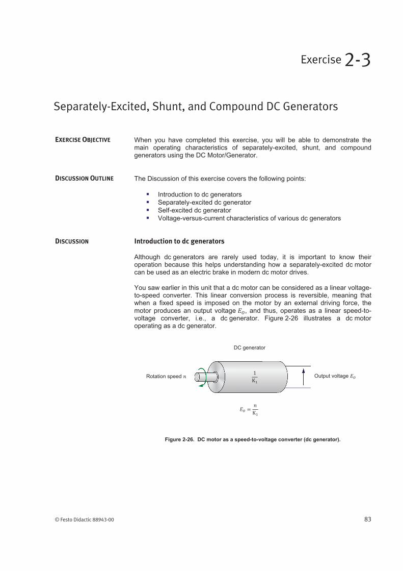
You saw earlier in this unit that a dc motor can be considered as a linear voltage-to-speed converter. This linear conversion process is reversible, meaning that when a fixed speed is imposed on the motor by an external driving force, the motor produces an output voltage , and thus, operates as a linear speed-to-voltage converter, i.e., a dc generator. Figure 2-26 illustrates a dc motor operating as a dc generator.
Figure 2-26. DC motor as a speed-to-voltage converter (dc generator).
Separately-Excited, Shunt, and Compound DC Generators
Exercise 2-3
EXERCISE OBJECTIVE
DISCUSSION OUTLINE
DISCUSSION
Rotation speed Output voltage
DC generator

Ex. 2-3 – Separately-Excited, Shunt, and Compound DC Generators Discussion
84 © Festo Didactic 88943-00
The linear relationship that exists between torque and current for the dc motor is also reversible and applies to the dc generator, i.e., a torque must be applied to the generator’s shaft to obtain a certain output current. Figure 2-27 illustrates a dc motor operating as a linear torque-to-current converter, i.e., a dc generator.
Figure 2-27. DC motor as a torque-to-current converter (dc generator).
Separately-excited dc generator
Figure 2-28a shows the output voltage-versus-speed relationship of a separately-excited dc generator. Figure 2-28b shows the output current-versus-applied torque relationship of a separately-excited dc generator. Notice that the slopes of these linear relationships are equal to the reciprocal of
constants and .
Figure 2-28. Input-output relationships of a separately-excited dc generator.
In a manner similar to that for a separately-excited dc motor, the field current of
a separately-excited dc generator can be varied to change the strength of the
field electromagnet, and thereby, the relative values of constant and . When the field current is decreased, constant increases and constant decreases, as for a separately-excited dc motor. As a result, the slope of the output voltage-versus-speed relationship decreases, whereas the slope of the output current-
Applied torque Output current
DC generator
Output voltage (V)
speed (r/min)
(a) Output voltage versus speed
Output current (A)
Applied torque (N m or lbf in)
(b) Output current versus applied torque

Ex. 2-3 – Separately-Excited, Shunt, and Compound DC Generators Discussion
© Festo Didactic 88943-00 85
versus-torque relationship increases. Conversely, when the field current is
increased, constant decreases and constant increases, and thereby, the slope of the output voltage-versus-speed relationship increases, whereas the slope of the output current-versus-torque relationship decreases. Therefore, the output voltage of a generator operating at a fixed speed can be varied by
varying the field current . This produces the equivalent of a dc power source
whose output voltage can be controlled by varying the field current .
Figure 2-29 shows the variation of output voltage for a separately-excited dc generator operating at a fixed speed, when the field current is varied from
zero to its nominal value.
Figure 2-29. Output voltage versus field current for a separately-excited dc generator
operating at a fixed speed.
The simplified equivalent electric circuit of a separately-excited dc generator is shown in Figure 2-30. It is the same as that for the dc motor, except that the direction of current flow is reversed and voltage becomes , which is the voltage induced across the armature winding as it rotates in the magnetic flux produced by the stator electromagnet. When no load is connected to the
dc generator output, the output current is zero and the output voltage
equals .
Figure 2-30. Simplified equivalent circuit of a dc generator.
Field current (A)
Fixed rotation speed
+
Ou
tpu
t vo
lta
ge
(
V)

Ex. 2-3 – Separately-Excited, Shunt, and Compound DC Generators Discussion
86 © Festo Didactic 88943-00
In the first exercise of this unit, you observed that when a fixed armature
voltage is applied to a separately-excited dc motor, its speed decreases as the armature current increases. You found that this decrease in speed is due to the armature resistance . Similarly, when the same motor operates as a generator and at a fixed speed, the armature resistance causes the output voltage to decrease with increasing output current, as shown in Figure 2-31.
Figure 2-31. Voltage-versus-current characteristic of a separately-excited dc generator (fixed speed).
The output voltage can be calculated by using the following equation:
(2-4)
where is the dc generator output voltage, expressed in volts (V). is the voltage induced across the armature winding, expressed in
volts (V).
is the armature resistance, expressed in ohms ( ).
is the dc generator output current, expressed in amperes (A).
Self-excited dc generator
The separately-excited dc generator provides flexible use because its characteristics can be changed by changing the field current. However, a separate dc power source is needed to excite the field electromagnet. This was a disadvantage when the first dc generators were used because dc sources were not commonly available at the time. Therefore, dc generators that operate without a dc power source were designed. This type of generator is referred to as self-excited dc generator.
In a self-excited dc generator, the field electromagnet is a shunt winding connected across the generator output (shunt generator) or a combination of a shunt winding connected across the generator output and a series winding connected in series with the generator output (compound generator). The generator output voltage and/or current excite(s) the field electromagnet. The
Output current (A)
Fixed rotation speedO
utp
ut
vo
lta
ge
(
V)

Ex. 2-3 – Separately-Excited, Shunt, and Compound DC Generators Discussion
© Festo Didactic 88943-00 87
way the field electromagnet is implemented (shunt or compound) determines many of the generator's characteristics.
Self-excitation is possible because of the residual magnetism in the stator pole pieces. As the armature rotates, a low voltage is induced across its winding and a low current flows in the shunt field winding. If this small field current is flowing in the proper direction, the residual magnetism is reinforced, which further increases the armature voltage. Thus, a rapid voltage build-up occurs. If the field current flows in the wrong direction, the residual magnetism is reduced and voltage build-up cannot occur. In this case, reversing the connections of the shunt field winding corrects the situation.
In a self-excited dc generator, the output voltage after build-up can have a polarity opposite to that required. This can be corrected by stopping the generator and setting the polarity of the residual magnetism. To set the residual magnetism, a dc power source is connected to the shunt field winding to force nominal current flow in the proper direction. Interrupting the current suddenly sets the polarity of the magnetic poles in the shunt field winding. When the generator is started once again, voltage build-up at the proper polarity occurs.
Voltage-versus-current characteristics of various dc generators
Figure 2-32 is a graph that shows the voltage-versus-current characteristics of various types of dc generators. As can be seen, the separately-excited dc generator and the shunt generator have very similar characteristics. The difference is that the output voltage of the shunt generator decreases a little more than that of the separately-excited dc generator as the output current increases. In both cases, the output voltage decreases because the voltage drop across the armature resistor increases as the output current increases. In the shunt generator, the voltage across the shunt field winding, and thereby, the field current, decreases as the output voltage decreases. This causes the output voltage to decrease a little more.
Figure 2-32. Voltage-versus-current characteristics of various dc generators.
It is possible to compensate the variation in output voltage by automatically changing the magnetic flux produced by the field electromagnet as the output current varies. The shunt and series field windings of a compound generator can
Output current (A)
Fixed rotation speedShunt generator
Differential compound generator
Separately-excited dc generator
Cumulative-compound generator
Ou
tpu
t vo
lta
ge
(
V)

Ex. 2-3 – Separately-Excited, Shunt, and Compound DC Generators Procedure Outline
88 © Festo Didactic 88943-00
be connected so that the magnetic flux increases when the output current increases. Thus, the output voltage remains fairly constant and changes very little as the output current increases as shown in Figure 2-32. This type of connection results in a cumulative compound generator because the magnetic fluxes created by the two field windings add together in a cumulative manner. For other applications where the output voltage must decrease rapidly when the output current increases, the shunt and series windings can be connected so that the magnetic fluxes subtract from each other, resulting in a differential compound generator.
The Procedure is divided into the following sections:
Set up and connections
Output voltage-versus-speed characteristic of a separately-excited dc generator
Output current-versus-torque characteristic of a separately-excited dc motor
Output voltage versus field current characteristic of a separately-excited dc generator
Output voltage-versus-output current characteristic of a separately-excited dc generator operating at a fixed speed
Additional experiments (optional)Output voltage-versus-output current characteristic of a shunt generator operating at a fixed speed. Voltage-versus-current characteristic of a cumulative-compound generator operating at a fixed speed. Output voltage-versus-output current characteristic of a differential compound generator operating at a fixed speed.
High voltages are present in this laboratory exercise. Do not make or modify any
banana jack connections with the power on unless otherwise specified.
Set up and connections
In this section, you will mechanically couple the DC Motor/Generator to the Four-Quadrant Dynamometer/Power Supply and set up the equipment.
1. Refer to the Equipment Utilization Chart in Appendix A to obtain the list of equipment required to perform the exercise. Install the equipment in the Workstation.
a Before performing the exercise, ensure that the brushes of the DC Motor/Generator are adjusted to the neutral point. To do so, connect a variable-voltage ac power source (terminals 4 and N of the Power Supply) to the armature of the DC Motor/Generator (terminals 1 and 2) through current input I1 of the Data Acquisition and Control Interface (DACI). Connect the shunt winding of the DC Motor/Generator (terminals 5 and 6) to voltage input E1 of the DACI. In LVDAC-EMS, open the Metering window. Set two meters to measure the rms values (ac) of the armature voltage and armature current at inputs E1 and I1 of the DACI, respectively. Turn the Power Supply on and adjust its voltage control knob so that an ac current
PROCEDURE OUTLINE
PROCEDURE

Ex. 2-3 – Separately-Excited, Shunt, and Compound DC Generators Procedure
© Festo Didactic 88943-00 89
(indicated by meter I1 in the Metering window) equal to half the nominal armature current flows in the armature of the DC Motor/Generator. Adjust the brush adjustment lever on the DC Motor/Generator so that the voltage across the shunt winding (indicated by meter E1 in the Metering window) is minimal. Turn the Power Supply off, close LVDAC-EMS, and disconnect all leads and cable.
Mechanically couple the DC Motor/Generator to the Four-Quadrant Dynamometer/Power Supply using a timing belt.
Before coupling rotating machines, make absolutely sure that power is turned off
to prevent any machine from starting inadvertently.
2. Make sure that the main power switch of the Four-Quadrant Dynamometer/Power Supply is set to the O (off) position, then connect its Power Input to an ac power wall outlet.
3. On the Power Supply, make sure that the main power switch and the 24 V ac power switch are set to the O (off) position, and that the voltage control knob is set to 0% (turned fully counterclockwise). Connect the Power Supply to a three-phase ac power outlet.
4. Connect the Power Input of the Data Acquisition and Control Interface (DACI) to the 24 V ac power source of the Power Supply.
Turn the 24 V ac power source of the Power Supply on.
5. Connect the USB port of the Data Acquisition and Control Interface to a USB port of the host computer.
Connect the USB port of the Four-Quadrant Dynamometer/Power Supply to a USB port of the host computer.
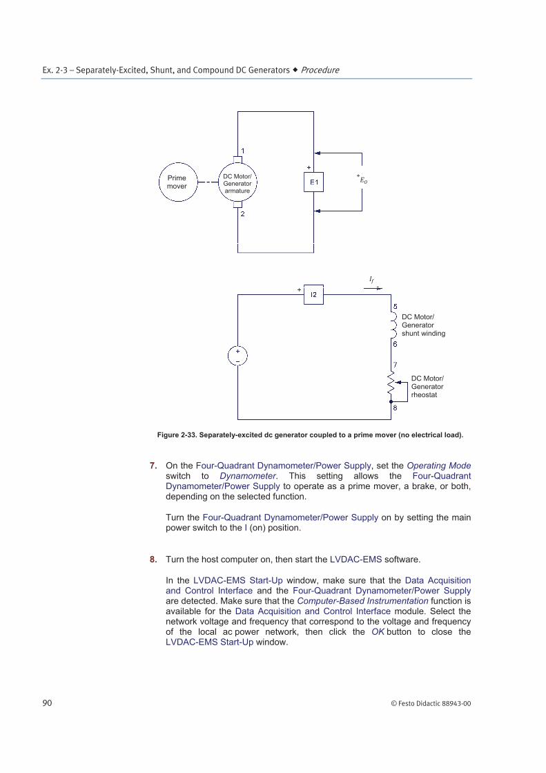
6. Connect the equipment as shown in Figure 2-33. Use the fixed dc voltage output of the Power Supply to implement the fixed-voltage dc power source. E1 and I2 are voltage and current inputs of the Data Acquisition and Control Interface (DACI). Notice that no electrical load is connected to the generator output.
Ex. 2-3 – Separately-Excited, Shunt, and Compound DC Generators Procedure
90 © Festo Didactic 88943-00
Figure 2-33. Separately-excited dc generator coupled to a prime mover (no electrical load).
7. On the Four-Quadrant Dynamometer/Power Supply, set the Operating Mode switch to Dynamometer. This setting allows the Four-Quadrant Dynamometer/Power Supply to operate as a prime mover, a brake, or both, depending on the selected function.
Turn the Four-Quadrant Dynamometer/Power Supply on by setting the main power switch to the I (on) position.
8. Turn the host computer on, then start the LVDAC-EMS software.
In the LVDAC-EMS Start-Up window, make sure that the Data Acquisition and Control Interface and the Four-Quadrant Dynamometer/Power Supply are detected. Make sure that the Computer-Based Instrumentation function is available for the Data Acquisition and Control Interface module. Select the network voltage and frequency that correspond to the voltage and frequency of the local ac power network, then click the OK button to close the LVDAC-EMS Start-Up window.
Prime mover
DC Motor/ Generator armature
+
DC Motor/ Generator shunt winding
DC Motor/ Generator rheostat

Ex. 2-3 – Separately-Excited, Shunt, and Compound DC Generators Procedure
© Festo Didactic 88943-00 91
9. In LVDAC-EMS, open the Four-Quadrant Dynamometer/Power Supply window, then make the following settings:
Set the Function parameter to CW Constant-Speed Prime Mover/Brake. This setting makes the Four-Quadrant Dynamometer/Power Supply operate as a clockwise prime mover/brake with a speed setting corresponding to the Speed parameter.
Set the Pulley Ratio parameter to 24:24. The first and second numbers in this parameter specify the number of teeth on the pulley of the Four-Quadrant Dynamometer/Power Supply and the number of teeth on the pulley of the machine under test (i.e., the DC Motor/Generator), respectively.
Make sure that the Speed Control parameter is set to Knob. This allows the speed of the clockwise prime mover/brake to be controlled manually.
Set the Speed parameter (i.e., the speed command) to 0 r/min. Notice that the speed command is the targeted speed at the shaft of the machine coupled to the prime mover, i.e., the speed of the DC Motor/Generator in the present case.
a The speed command can also be set by using the Speed control knob in the Four-Quadrant Dynamometer/Power Supply window.
10. In LVDAC-EMS, open the Metering window. Set two meters to measure the
dc generator output voltage (E1) and field current (I2).
Click the Continuous Refresh button to enable continuous refresh of the values indicated by the various meters in the Metering application.
Output voltage-versus-speed characteristic of a separately-excited dc generator
In this section, you will set the field current of the separately-excited dc generator to the same value as that used in Exercise 2-1. You will measure data and plot a graph of the generator output voltage as a function of speed when no electrical load is connected to the generator output. You will calculate the slope of the voltage-versus-speed relationship and compare it to constant determined in Exercise 2-1 when the DC Motor/Generator was operating as a separately-excited dc motor.
11. In the Four-Quadrant Dynamometer/Power Supply window, start the CW Constant-Speed Prime Mover/Brake by clicking the Start/Stop button or by setting the Status parameter to Started.
Turn the Power Supply on by setting the main power switch to I (on).

Ex. 2-3 – Separately-Excited, Shunt, and Compound DC Generators Procedure
92 © Festo Didactic 88943-00
12. On the DC Motor/Generator, set the Field Rheostat knob so that the
dc generator field current (meter I2) is equal to the value given in Table 2-4
for your local ac power network.
Table 2-4. Field current .
Local ac power network Field current
(mA) Voltage (V)
Frequency (Hz)
120 60 300
220 50 190
240 50 210
220 60 190
13. In LVDAC-EMS, open the Data Table window. Set the Data Table to record
the dc generator output voltage and field current (indicated by
meters E1 and I2 in the Metering window), as well as the dc generator rotation speed and torque (indicated by the Speed and Torque meters in the Four-Quadrant Dynamometer/Power Supply window).
14. Increase the prime mover speed from 0 to 1500 r/min by 150 r/min increments, using the Speed parameter in the Four-Quadrant Dynamometer/Power Supply window. For each speed setting, record the dc generator output voltage and field current , as well as the
dc generator speed and torque in the Data Table.
15. When all data has been recorded, set the Speed parameter in the Four-Quadrant Dynamometer/Power Supply window to 0 r/min, then click the Start/Stop button in this window to stop the CW Constant-Speed Prime Mover/Brake.
Turn the Power Supply off by setting its main power switch to the O (off) position. (Leave the 24 V ac power source of the Power Supply turned on).
In the Data Table window, confirm that the data has been stored, save the data file under filename DT231, and print the data table if desired.
16. In the Graph window, make the appropriate settings to obtain a graph of the
dc generator output voltage as a function of the dc generator speed . Name the graph “G231”, name the x-axis “DC generator speed”, name the y-axis “DC generator output voltage”, and print the graph if desired.

Ex. 2-3 – Separately-Excited, Shunt, and Compound DC Generators Procedure
© Festo Didactic 88943-00 93
Does this graph confirm that the separately-excited dc generator is equivalent to a linear speed-to-voltage converter, with higher speed producing greater output voltage?
Yes No
17. Use the two end points to calculate the slope of the relationship obtained in graph G231. The values of these points are indicated in data table DT231.
Compare the slope of the output voltage-versus-speed relationship to
constant obtained in Exercise 2-1.
18. In the Data Table window, clear the recorded data.
Output current-versus-torque characteristic of a separately-excited dc motor
In this section, you will connect an electrical load to the generator output. You will measure data and plot a graph of the separately-excited dc generator output current as a function of the torque applied to the generator shaft, when the generator rotates at a fixed speed You will calculate the slope of the current-versus-torque relationship and compare it to constant determined in Exercise 2-1 when the DC Motor/Generator was operating as a separately-excited dc motor.
19. Connect a load resistor ( ) in series with a dc ammeter (I1) across the separately-excited dc generator output, as shown in Figure 2-34. I1 is a current input of the Data Acquisition and Control Interface (DACI). Use the
Resistive Load module to implement resistor . Set the resistance value of to infinite ( ) by connecting the three resistor sections of the Resistive Load module in parallel and setting the levers of all toggle switches to the O (off) position. Leave all other connections unchanged.

Ex. 2-3 – Separately-Excited, Shunt, and Compound DC Generators Procedure
94 © Festo Didactic 88943-00
Figure 2-34. Separately-excited dc generator coupled to a prime mover (with an electrical load).
20. In the Metering window, make sure that the meters are set to measure the
dc generator output voltage (E1), output current (I1), and field current (I2). Make sure that the Data Table is set to record the
dc generator output voltage , output current , and field current as well
as the dc generator rotation speed and torque .
21. In the Four-Quadrant Dynamometer/Power Supply window, set the Speed parameter so that the prime mover speed is equal to the nominal speed of the DC Motor/Generator. Start the CW Constant-Speed Prime Mover/Brake to make the prime mover rotate.
a The nominal speed value of the DC Motor/Generator is indicated in the lower section of its front panel.
Turn the Power Supply on by setting the main power switch to (on).
Prime mover
DC Motor/ Generator armature
+
DC Motor/ Generator shunt winding
DC Motor/ Generator rheostat

Ex. 2-3 – Separately-Excited, Shunt, and Compound DC Generators Procedure
© Festo Didactic 88943-00 95
On the DC Motor/Generator, slightly readjust the Field Rheostat knob, if
necessary, so that the field current indicated by meter I2 still equals the
value given in Table 2-4 for your local ac power network.
22. Record the dc generator output voltage , output current , and field
current , as well as the rotation speed and torque in the Data Table.
Then, modify the settings on the Resistive Load module to decrease the resistance of resistor by steps as indicated in Table 2-5 for your local ac power network. (You can refer to Appendix C of this manual to know how to obtain the various resistance values given in Table 2-5). For each resistance setting, readjust (if necessary) the Speed parameter value in the Four-Quadrant Dynamometer/Power Supply window so that the prime mover speed remains equal to the nominal speed of the DC Motor Generator, and
then record the dc generator output voltage , output current , and field current , as well as the rotation speed and torque in the Data Table.
The dc generator output voltage will exceed the rated voltage of the Resistive Load
module. Therefore, perform this manipulation in less than 5 minutes.
Table 2-5. Decreasing the resistance value of to load the dc generator.
Local ac power network
Resistance value of resistor ( )
Voltage (V) Frequency
(Hz)
120 60 1200 600 300 171 120 86 71 57
220 50 4400 2200 1100 629 440 314 259 210
240 50 4800 2400 1200 686 480 343 282 229
220 60 4400 2200 1100 629 440 314 259 210
23. When all data has been recorded, set the Speed parameter in the Four-Quadrant Dynamometer/Power Supply window to 0 r/min, then click the Start/Stop button in this window to stop the CW Constant-Speed Prime Mover/Brake.
Turn the Power Supply off by setting its main power switch to the O (off) position. (Leave the 24 V ac power source of the Power Supply turned on).
In the Data Table window, confirm that the data has been stored. Reverse the polarity of the torque values recorded in the data table to obtain the torque applied to the dc generator’s shaft. Save the data table under filename DT232, and print the data table if desired.
24. In the Graph window, make the appropriate settings to obtain a graph of the dc generator output current as a function of the torque applied to the generator’s shaft. Name the graph “G232”, name the x-axis “Torque applied

Ex. 2-3 – Separately-Excited, Shunt, and Compound DC Generators Procedure
96 © Festo Didactic 88943-00
to the dc generator’s shaft”, name the y-axis “DC generator output current”, and print the graph if desired.
a The torque is not zero when the generator output current is zero because some torque is required to overcome opposition to rotation due to friction in the dc generator.
Does this graph confirm that the separately-excited dc generator is equivalent to a torque-to-current converter, with higher torque producing greater output current?
Yes No
25. Use the two end points to calculate the slope of the relationship obtained in graph G232. The values of these points are indicated in data table DT232.
Compare the slope of the output current-versus-torque relationship to constant obtained in Exercise 2-1.
26. In the Data Table window, clear the recorded data.
Output voltage versus field current characteristic of a separately-excited dc generator
In this section, you will vary the field current of the separately-excited
dc generator and observe how the output voltage is affected.
27. On the Resistive Load module, set the resistance of resistor to the value given in Table 2-6.
Table 2-6. Resistance value to be set for .
Local ac power network Resistance value of
resistor ( ) Voltage (V) Frequency
(Hz)
120 60 171
220 50 629
240 50 686
220 60 629

Ex. 2-3 – Separately-Excited, Shunt, and Compound DC Generators Procedure
© Festo Didactic 88943-00 97
28. In the Four-Quadrant Dynamometer/Power Supply window, set the Speed parameter to the nominal speed value of the DC Motor/Generator. Start the CW Constant-Speed Prime Mover/Brake to make the prime mover rotate.
Turn the Power Supply on by setting the main power switch to I (on).
On the DC Motor/Generator, readjust the Field Rheostat knob, if necessary, so that field current (meter I2) still equals the value indicated in Table 2-4
for your local ac power network. Note and record the dc generator output
voltage (meter E1) and field current (meter I2).
V
A
29. On the DC Motor/Generator, slowly turn the Field Rheostat knob fully
clockwise so that the field current (meter I2) increases. While doing this,
observe the dc generator output voltage (meter E1).
The dc generator output voltage will exceed the rated voltage of the Resistive Load
module while performing this manipulation. Therefore, perform this manipulation within
1 minute.
Note and record the dc generator output voltage (meter E1) and field
current (meter I2).
V
A
On the DC Motor/Generator, set the Field Rheostat knob to the mid position.
Describe what happens to the dc generator output voltage when the field current is increased.
30. On the DC Motor/Generator, slowly turn the Field Rheostat knob fully
counterclockwise so that the field current (meter I2) decreases. While
doing this, observe the dc generator output voltage (meter E1).
Note and record the dc generator output voltage (meter E1) and field current (meter I2).
V
A

Ex. 2-3 – Separately-Excited, Shunt, and Compound DC Generators Procedure
98 © Festo Didactic 88943-00
Describe what happens to the dc generator output voltage when the field current is decreased.
Is a separately-excited dc generator equivalent to a dc power source with variable output voltage?
Yes No
31. In the Four-Quadrant Dynamometer/Power Supply window, set the Speed parameter to 0 r/min, then click the Start/Stop button in this window to stop the CW Constant-Speed Prime Mover/Brake.
Turn the Power Supply off by setting its main power switch to the O (off) position. (Leave the 24 V ac power source of the Power Supply turned on).
Output voltage-versus-output current characteristic of a separately-excited dc generator operating at a fixed speed
In this section, you will use the data obtained previously to plot a graph of the dc generator output voltage as a function of the dc generator output current, for a fixed speed.
32. In the Graph window, make the appropriate settings to obtain a graph of the separately-excited dc generator output voltage as a function of the
dc generator output current output using the data recorded previously in the data table (DT232). Name the graph “G232-1”, name the x-axis “DC generator output current”, name the y-axis “DC generator output voltage”, and print the graph if desired.
Describe how the dc generator output voltage varies as the output current increases.
a If you want to perform the additional experiments, skip the next step, then return to it when all additional manipulations are finished.
33. On the Power Supply, make sure that the main power switch is set to the O (off) position, then turn the 24 V ac power source off. Close the LVDAC-EMS software. Turn the Four-Quadrant Dynamometer/Power Supply off. Disconnect all leads and return them to their storage location.

Ex. 2-3 – Separately-Excited, Shunt, and Compound DC Generators Procedure
© Festo Didactic 88943-00 99
Additional experiments (optional)
Output voltage-versus-output current characteristic of a shunt generator operating at a fixed speed
You can obtain the output voltage-versus-output current characteristic of a shunt generator and compare it to that obtained for the separately-excited dc generator. To do so, make sure the Power Supply is turned off [voltage control knob set to 0% and main power switch set to the O (off) position] and connect the fixed dc voltage output (terminals 8 and N) of the Power Supply across the shunt winding (terminals 5 and 6) of the DC Motor/Generator. On the Power Supply, set the main power switch to the I (on) position, then set it to the O (off) position. This sets the polarity of the residual magnetism. Set up the shunt generator circuit shown in Figure 2-35. Set the Field Rheostat knob to the 0- position
(turned fully clockwise). Set the resistance value of to infinite ( ) for now.
Figure 2-35. Shunt generator coupled to a prime mover (with an electrical load).
In the Four-Quadrant Dynamometer/Power Supply window, set the Speed parameter so that the prime mover speed is equal to the nominal speed of the DC Motor/Generator. Start the CW Constant-Speed Prime Mover/Brake to make the prime mover rotate. On the DC Motor/Generator, adjust the Field Rheostat
knob so that the field current is equal to the value indicated in Table 2-4 for
your local ac power network. Clear the data recorded in the Data Table. Refer to steps 22 and 23 of this exercise to record the necessary data and save the data table under filename DT233. Refer to step 32 to obtain the graph and name this graph G233. Compare the output voltage-versus-output current characteristic of the shunt generator (graph G233) to that of the separately-excited dc generator (graph G232-1).
a The output voltage of the shunt generator decreases rapidly as the output current increases because the armature resistance of the DC Motor/Generator is quite large. This is also due to another phenomenon which is called armature reaction. This phenomenon will be studied in the next unit of this manual.
Prime mover
DC Motor/ Generator armature
+
DC Motor/ Generator shunt winding
DC Motor/Generatorrheostat

Ex. 2-3 – Separately-Excited, Shunt, and Compound DC Generators Procedure
100 © Festo Didactic 88943-00
Voltage-versus-current characteristic of a cumulative-compound generator operating at a fixed speed
You can obtain the output voltage-versus-output current characteristic of a cumulative compound generator and compare it to that obtained for the separately-excited dc generator. To do so, carry out the same manipulations as those used to obtain the output voltage-versus-output current characteristic of the shunt generator using the circuit of a cumulative compound generator shown in Figure 2-36. Save the data table under filename DT234 and name the graph “G234”. Compare the output voltage-versus-output current characteristic of the cumulative compound generator (graph G234) to those of the separately-excited dc generator (graph G232-1) and shunt generator (graph G233) obtained previously.
Figure 2-36. Cumulative-compound generator coupled to a prime mover (with an electrical load).
Prime mover
DC Motor/ Generator armature
+
DC Motor/ Generator shunt winding
DC Motor/ Generator rheostat
DC Motor/ Generator
series winding

Ex. 2-3 – Separately-Excited, Shunt, and Compound DC Generators Procedure
© Festo Didactic 88943-00 101
Output voltage-versus-output current characteristic of a differential compound generator operating at a fixed speed
You can obtain the output voltage-versus-output current characteristic of a differential compound generator and compare it to that obtained for the separately-excited dc generator. To do so, carry out the same manipulations as those used to obtain the output voltage-versus-output current characteristic of the shunt generator using the circuit of a differential compound generator shown in Figure 2-37. Save the data table under filename DT235 and name the graph “G235”. Compare the output voltage-versus-output current characteristic of the differential compound generator (graph G235) to those obtained with the other types of dc generators (graphs G232-1, G233, and G234).
Figure 2-37. Differential-compound generator coupled to a prime mover (with an electrical load).
Prime mover
DC Motor/ Generator armature
+
DC Motor/ Generator shunt winding
DC Motor/ Generator rheostat
DC Motor/ Generator
series winding

Ex. 2-3 – Separately-Excited, Shunt, and Compound DC Generators Conclusion
102 © Festo Didactic 88943-00
In this exercise, you plotted graphs of the main operating characteristics of a separately-excited dc generator. You observed that the output voltage increases linearly with speed. You also observed that the output current increases linearly with the input torque. You found that the slope of the output voltage-versus-
speed characteristic is equal to the reciprocal of constant , and that the slope of the output current-versus-torque characteristic is equal to the reciprocal of
constant . You saw that constant and can be changed by changing the field current, and that this allows the output voltage to be changed. You observed that the output voltage decreases as the output current increases.
If you performed the additional experiments, you plotted graphs of the voltage-versus-current characteristics for shunt, cumulative compound, and differential compound generators. You compared the various voltage-versus-current characteristics obtained in the exercise. You observed that the output voltage of the shunt generator decreases more rapidly than that of the separately-excited dc generator when the output current increases. You found that the output voltage of a cumulative compound generator varies little as the output current varies. Finally, you saw that the output voltage of a differential compound generator decreases more rapidly than that of the separately-excited and shunt generators when the output current increases.
1. What effect does decreasing the field current have on the output voltage of a separately-excited dc generator operating at fixed speed?
2. What effect does increasing the output current have on the input torque of a separately-excited dc generator?
3. What is the main characteristic of a cumulative compound generator?
4. What is the main characteristic of a differential compound generator?
5. What happens when the field current of a separately-excited dc generator is increased and the speed is maintained constant?
CONCLUSION
REVIEW QUESTIONS