
E MBEDDED CELLAR - pestingers.net · Circuit Cellar Incorporated, 4 Park Street, Suite 20, Vernon,...
70
CELLAR CIRCUIT T H E C O M P U T E R A P P L I C A T I O N S J O U R N A L ® INK $3.95 U.S. $4.95 Canada # 9 1 F E B R U A R Y 1 9 9 8 COMMUNICATIONS Making NT Play Nice with Unix Embedding Voice Recognition Zilog’s Z89xx3 = DSP + MCU Converting PC GUIs for NonPC Devices E MBEDDED PC MONTHLY SECTION
Transcript of E MBEDDED CELLAR - pestingers.net · Circuit Cellar Incorporated, 4 Park Street, Suite 20, Vernon,...

CELLARCIRCUITT H E C O M P U T E R A P P L I C A T I O N S J O U R N A L
®INK
$3.95 U.S.$4.95 Canada
# 9 1 F E B R U A R Y 1 9 9 8
COMMUNICATIONSMaking NT Play Nice with Unix
Embedding Voice Recognition
Zilog’s Z89xx3 =DSP + MCU
Converting PC GUIsfor NonPC Devices
EM
BEDDEDPCM
ONTHLY SECTION

2 Issue 91 February 1998 Circuit Cellar INK®
T H E C O M P U T E R A P P L I C A T I O N S J O U R N A L
®INKEDITORIAL DIRECTOR/PUBLISHERSteve Ciarcia
EDITOR-IN-CHIEFKen Davidson
MANAGING EDITORJanice Hughes
TECHNICAL EDITORElizabeth Laurençot
WEST COAST EDITORTom Cantrell
CONTRIBUTING EDITORSRick LehrbaumFred Eady
NEW PRODUCTS EDITORHarv Weiner
ASSOCIATE PUBLISHERSue (Hodge) Skolnick
CIRCULATION MANAGERRose Mansella
BUSINESS MANAGERJeannette Walters
ART DIRECTORKC Zienka
ENGINEERING STAFFJeff Bachiochi
PRODUCTION STAFFJohn Gorsky
James Soussounis
And Yet More Change
Cover photograph Ron Meadows – Meadows MarketingPRINTED IN THE UNITED STATES
For information on authorized reprints of articles,contact Jeannette Walters (860) 875-2199.
Circuit Cellar INK® makes no warranties and assumes no responsibility or liability of any kind for errors in theseprograms or schematics or for the consequences of any such errors. Furthermore, because of possible variation inthe quality and condition of materials and workmanship of reader-assembled projects, Circuit Cellar INK® disclaimsany responsiblity for the safe and proper function of reader-assembled projects based upon or from plans, descriptions,or information published in Circuit Cellar INK®.Entire contents copyright © 1998 by Circuit Cellar Incorporated. All rights reserved. Circuit Cellar INK is a registeredtrademark of Circuit Cellar Inc. Reproduction of this publication in whole or in part without written consent from CircuitCellar Inc. is [email protected]
TASK MANAGER
i n my tenth-anniversary editorial last month, Ispent some time talking about change—specifi-
cally, the changes that have come about over the pastdecade. One area in which we’ve seen drastic change just
in the past few years is how we communicate.Printed publications have been around since the printing press was
invented in the 15th century, and will continue to thrive for the foreseeablefuture. There is something about holding a book or magazine that peoplestill enjoy and aren’t willing to give up. They don’t require special equipmentto read. They’re lightweight, low cost, highly portable, and don’t require anypower. On the downside are the cost of entry, use and cost of paper,required lead time, and limited distribution.
Along came the electronic bulletin board system, and suddenly timeand distance were compressed, enabling anybody with a computer andmodem to publish their own work for anyone in the world to accessinstantly. The next step was the Internet and the World Wide Web, furtherreducing cost and increasing availability and quality.
Publishers of print media are seeing the handwriting on the wall in abig way, and virtually everybody has some kind of on-line version of theirprint publication. We at Circuit Cellar brought the Circuit Cellar BBS on-lineback in 1986 to first support Steve’s BYTE articles and to later supportCircuit Cellar INK. It was a tremendous success, fueling active discussionsbetween talented engineers located throughout the world. Long-timereaders were also treated to a sampling of those discussions each monththrough my ConnecTime column.
The Circuit Cellar BBS has just gone off-line for good as a BBS.However, various Internet elements have replaced it, making the samefunctions available to anyone in the world with Internet access. Magazineinformation and articles can be obtained from the Circuit Cellar Web site(www.circuitcellar.com). Files can be downloaded from our FTP site(ftp.circuitcellar.com). And, messages can be exchanged in a public forumthrough our new newsgroup server. Don’t look for our newsgroups among theother Usenet groups you may be receiving from your ISP (Internet ServiceProvider), though. You must point your newsreader at our server atbbs.circuitcellar.com to see what groups are available and what discus-sions are going on. If you’re still not sure what I’m talking about, there is moreinformation on the Web site.
In the coming months, I’ll be spending more time enhancing anddeveloping our on-line presence. Please send any suggestions orcomments along with those article proposals and ideas to [email protected] and I'll respond as quickly as possible. I’ll see you on-line!
CONTACTING CIRCUIT CELLAR INKSUBSCRIPTIONS:
INFORMATION: www.circuitcellar.com or [email protected] SUBSCRIBE: (800) 269-6301 or via our editorial offices: (860) 875-2199
GENERAL INFORMATION:TELEPHONE: (860) 875-2199 FAX: (860) 871-0411INTERNET: [email protected], [email protected], or www.circuitcellar.comEDITORIAL OFFICES: Editor, Circuit Cellar INK, 4 Park St., Vernon, CT 06066
AUTHOR CONTACT:E-MAIL: Author addresses (when available) included at the end of each article.ARTICLE FILES: ftp.circuitcellar.com
CIRCUIT CELLAR INK®, THE COMPUTER APPLICATIONS JOURNAL (ISSN 0896-8985) is published monthly byCircuit Cellar Incorporated, 4 Park Street, Suite 20, Vernon, CT 06066 (860) 875-2751. Periodical rates paid atVernon, CT and additional offices. One-year (12 issues) subscription rate USA and possessions $21.95,Canada/Mexico $31.95, all other countries $49.95. Two-year (24 issues) subscription rate USA andpossessions $39, Canada/Mexico $55, all other countries $85. All subscription orders payable in U.S. fundsonly via VISA, MasterCard, international postal money order, or check drawn on U.S. bank.Direct subscription orders and subscription-related questions to Circuit Cellar INK Subscriptions,P.O. Box 698, Holmes, PA 19043-9613 or call (800) 269-6301.Postmaster: Send address changes to Circuit Cellar INK, Circulation Dept., P.O. Box 698, Holmes, PA 19043-9613.
ADVERTISINGADVERTISING SALES REPRESENTATIVE
Bobbi Yush Fax: (860) 871-0411(860) 872-3064 Email: [email protected]
ADVERTISING COORDINATORValerie Luster Fax: (860) 871-0411(860) 875-2199 Email: [email protected]

Circuit Cellar INK® Issue 91 February 1998 3
ISSUEINSIDE
Low-Cost Voice RecognitionBrad Stewart
Building an Embedded Web Server from ScratchRichard Ames
Integrating Windows NT 4.0 into a TCP/IP EnvironmentBill Payne
CodesignThe Evolving Relationship Between Hardware and SoftwareRichard Moseley
Choosing the Right Crystal for Your OscillatorNorman Bujanos
I MicroSeriesEMI Gone TechnicalPart 1: Surge SuppressionJoe DiBartolomeo
I From the BenchChoose the Right Vehicle Before Riding the Air WavesJeff Bachiochi
I Silicon UpdateDouble-Duty DSPTom Cantrell
2
6
8
65
96
EMBE
DDED
PC12203060
6672
78
82
36 Nouveau PCedited by Harv Weiner
40 Converting PC GUIs for NonPC Devices Dan Johnson
47 RPC Real-Time PCReal-Time Operating SystemsPart 2: RTOS InterfacingMarc Guillemont
53 APC Applied PCsRF TelemetryPart 2: You’re on the AirFred Eady
www.c i rcu i tce l lar .com
9191
Task ManagerKen Davidson
And Yet More Change
Reader I/O
New Product Newsedited by Harv Weiner
Advertiser’s Index
Priority InterruptSteve Ciarcia
Techno-Jargon

6 Issue 91 February 1998 Circuit Cellar INK®
READER I/OTHAT DARN x-y RATIO
As a broadcast professional with over 20 years in the(PAL) business, I was happy to read Do-While Jones’article “HDTV—The New Digital Direction,” (INK 86).Anything that helps people understand how high band-width content travels along a limited-size pipe is good.
One very minor mistake that I’ve seen made a thou-sand times is the reference to a 4 × 3 video wall. If youstack monitors symmetrically 4 across × 3 vertically,you end up with a 16:9 video wall—oops! To retain theaspect ratio of the individual monitors, you need toexpand both dimensions by the same ratio!
Michael [email protected]
RENAMING “FUZZY LOGIC”Ken’s editorial in INK 88 (“Stuffed Mentality”) made
a good point—“fuzzy logic” sounds like fuzzy thinking.I suggest we rename it “quantitative logic.” It is logic inwhich truth is a quantity (i.e., something you can havea little or a lot of).
There are other nonclassical logics, too. I’m currentlydoing research on defeasible logic, a system where gen-eralizations are automatically overruled by specificexceptions. It’s a good fit to the way human beings de-scribe things.
Michael A. [email protected]
SLACKING OFF?A programmer friend passed me a copy of INK 88 for
the articles on automotive applications for fuzzy con-trols. Constantin von Altrock’s “Fuzzy Logic in Auto-motive Engineering” was very clear and gave me amuch better understanding of how and why fuzzy logicis being used. Unfortunately, Constantin shows his lackof automotive background (and/or the results of readinga poorly translated paper) in a couple of places—thearticle would have been much more convincing withoutthese mistakes.
First of all, when the car is moving and a wheel stopsturning, it is “locked” (not “blocked”).
Also, the variable s in the text (p. 13) and in Figure 1is “slip ratio” (not “slack”). There are a number ofdefinitions for s used in different parts of the world.
There’s a summary of eight different slip-ratio relation-ships starting on p. 39 of Race Car Vehicle Dynamics(W.F. and D.L. Milliken, SAE, www.sae.org, 1995).
In Figure 1, the curve for “Snowy Road” would per-haps be more accurate if labeled “Hard Packed Snow”.The three curves shown are all representative of tireperformance on “hard” surfaces, where there is a definitepeak in m (tire-road friction coefficient).
To give but one example of the difficulty of designingan ABS algorithm, consider that unpacked snow, gravel,and sand are all “deformable” surfaces, and braking ondeformable surfaces has a completely different charac-teristic than on hard surfaces. On a deformable surface,a locked wheel usually gives the best braking (but nosteering control), perhaps by building up a wedge ofmaterial in front of the tire. I say “perhaps” becausetire-road friction on different surfaces is still not wellunderstood. The inability of current production ABSs toproperly distinguish between different surfaces remainsa major problem.
The stopping ability of ABS on various slippery sur-faces was discussed in a recent article (D. Simanaitis,“ABS: Putting a Stop to it All,” Road & Track, July1997). In their tests, locking the brakes (with the Mer-cedes-Benz ABS disarmed) produced shorter stoppingdistances on three out of four different icy/snowy sur-faces tested. The ABS also lost on gravel and tied on sand.ABS won on wet roads and won dramatically on dry roads.
Douglas [email protected]
Thanks for such detailed feedback. I’d like to brieflycomment on your issues.
I have no doubt that it’s “locking” instead of “block-ing.” I used “blocking” because “ABS” stands for Anti-Blockier System in German.
Regarding s, the German is “Schlupf,” which in tech-nical dictionaries is translated to “slack” (which Ox-ford defines more precisely than it does “slip”). And,you’re right: s has many definitions worldwide. Ratherthan discussing these, I took one, showed the definition,and focussed on fuzzy-logic use in this system. I don’tthink any other approach would have helped the reader.
I limited the discussion on hard surfaces becausediscussing all the different things that occur within anABS situation was not my goal. But, you’re absolutelycorrect: there’s a lot more to say about ABS.
Constantin von [email protected]

8 Issue 91 February 1998 Circuit Cellar INK®
NEW PRODUCT NEWSEdited by Harv Weiner
BATTERY POWER MINDERThe bq2018 Power Minder IC
provides state-of-charge informa-tion for any type of rechargeablebattery, including Li-Ion, NiMH,NiCd, lead acid, and recharge-able alkaline. Designed for bat-tery-pack integration, the 8-pinbq2018 communicates criticalbattery information over asingle-wire control/data serialinterface to an intelligent hostcontroller. Typical applicationsinclude cell phones, PDAs, andpersonal organizers.
The bq2018 measures thevoltage drop across a low-valueseries sense resistor between thebattery’s negative terminal andthe battery-pack ground contact.By using the accumulated countsin the charge, discharge, and self-discharge registers, an intelligent host controller can deter-mine battery state-of-charge information. An internal offsetcount register improves accuracy.
The bq2018 features 128 bytes of NVRAM, including115 bytes of user RAM for storing battery characteristics,charge data, or ID information, thus eliminating the need
PROCESSOR PROTECTOR
for a separate battery ID chip.An internal ADC and refer-ence operate from 2.8 to 5.5 Vand at less than 80 µA. Stand-by-mode current is less than10 µA and data-retention cur-rent is less than 50 nA, socritical information can bestored for over 10 years with5 mAh of battery capacity.
The 8-pin, 150-mil SOICpackage of the bq2018 is smallenough to fit in the crevicebetween two adjacent cells. Itis priced at $1.85 in 10k quan-tities. The bq2118 PowerMinder miniboard incorpo-rates all of the necessary com-ponents for a fully functionalimplementation that sells for$4.40 in 10k quantities.
Benchmarq Microelectronics, Inc.17919 Waterview Pkwy.Dallas, TX 75252(972) 437-9195Fax: (972) 437-9198www.benchmarq.com #501
Processor Protector pro-vides a simple means toconfirm the proper values.
The Processor Protectorplugs into the CPU socketand indicates the value ofthe core and I/O voltagesapplied on a two-digit LED.Lights on the unit indicatewhich voltage is being mea-sured. The Processor Pro-tector is compatible withSocket 5 and 7 mother-boards and sells for $59.
Incorrect jumpersettings for the dualvoltage levels on newmicroprocessors manu-factured by AMD, IBM,Cyrix, and Intel canshorten CPU life andcause erratic operation.System lockup, memoryerrors, and other inter-mittent phenomenamay be the result of anover- or under-voltagecondition. Poorly writ-ten instruction manualsand the limitations ofverifying the core volt-age on the chip are tworeasons why incorrectsettings can occur. The
Autotime6605 SW Macadam Blvd.Portland, OR 97201(503) 452-8577 • Fax: (503) 452-8495www.autotime.com #502

Circuit Cellar INK® Issue 91 February 1998 9
TMS320C6x SINGLE-PROCESSOR DEVELOPMENT SYSTEM
NEW PRODUCT NEWSThe HEVAL6A TMS320C6x single-pro-
cessor development system integrates a200-MHz (1600 MIPS) TI TMS320C6201processor with several memory types, in-cluding SBSRAM, SDRAM, and asynchro-nous SRAM. A mezzanine slot supporting apair of serial interfaces and two I/O inter-face slots supporting a variety of data-acqui-sition and communications modules enabledevelopers to integrate the hardware intotheir chosen application environment. TheDSP hardware can be programmed and de-bugged via the PC board’s 16-bit ISA-bushost interface and JTAG controller. It canbe booted without a host computer (forstand-alone or embedded applications) viaits onboard flash memory.
Development tools include the TI ’C6xCode Development Tools (C compiler, assembly opti-mizer, assembler, and linker), software loader utility,GO DSP Code Composer for C source debugging, andPC-based API for DOS and Windows.
The HEVAL6A is priced at $14,000.
Traquair Data Systems, Inc.114 Sheldon Rd.Ithaca, NY, 14850(607) 266-6000 • Fax: (607) 266-8221www.traquair.com #503
POWER-TO-FREQUENCY CONVERTERThe AD7750 is designed for residential and industrial
power-metering applications. It can be configured forpower measurement, voltage-to-frequency conversion,or converting the product of two voltages to a frequency.
It contains two ADCs, a multiplier, offset compensa-tor, digital-to-frequency converter, reference, and otherconditioning circuitry. Both channels are driven bydifferential gain amplifiers—channel 1 with selectable
gains of 1 and 16, and channel 2 with a gain of 2. Ahigh-pass filter can be switched into the signal path ofone channel to remove offset effects.
The AD7750’s switched-capacitor architecture al-lows a bipolar analog input of 11 V with a single 5-Vpower supply. Nonlinearity for either input is less than0.05% maximum.
The device features two sets of frequency outputsthat consist of fixed-width pulse streams with pin-selectable frequencies. Low frequencies are suitable forstepping motors, while higher frequency pulse streamsare appropriate for calibration and test. In the signed mode,outputs can be configured to represent the result offour-quadrant multiplication. In the unsigned mode,magnitude-only outputs are always positive regardlessof the input polarities. A reverse-power indicator activateswhen negative power is detected in the unsigned mode.
The AD7750 comes in 20-pin SOIC and DIP pack-ages and is priced at $2.50 in 100,000-piece quantities.
Analog Devices, Inc.804 Woburn St. • Wilmington, MA 01887(781) 937-1428 • Fax: (781) 821-4273www.analog.com #504

10 Issue 91 February 1998 Circuit Cellar INK®
NEW PRODUCT NEWSSCOPE UTILITY SYSTEM
EZ-View-SA functions as a data-acquisition system,oscilloscope, digital voltmeter, and chart recorder. Thehardware module attaches to a parallel printer port andprovides six single-ended channels of input with 12-bitresolution. An input range of ±10 VDC is available atan input impedance of 330 kΩ.
The software features auto-installation and configu-ration, mouse or keyboard control, remote start, andtrigger controls. It works with all MS-DOS-, Win3.1-,and Win95-based computers with ’386 or higher pro-cessors and VGA or better screens. Operating modesinclude real-time monitoring (oscilloscope), data ac-quisition (record), and rapid record (burst).
Features include gain adjustments, bias offsets,scale selection, variable sampling-rate and run-timeselection, channel labeling, triggering, auto-scaling,and remote-start options. Acquired data can be trans-ported to standard spreadsheets and expanded for de-tailed analysis. A notes feature permits a brief textdescription of the data to be attached to saved files.
EZ-View-SA costs $199, including the data-acquisi-tion module, power supply, data cable, instruction
manual, and screwdriver. Options include 16-bit dataresolution, remote battery power supply, and probes.
Mid-Atlantic Systems Co.2284 Golden Pond Ct. • Fenton, MI 48430-1097(810) 750-4140 • Fax: (810) 629-4988www.mid-atl-sys.com ` #505

Circuit Cellar INK® Issue 91 February 1998 11
NEW PRODUCT NEWSWIRELESS KEYBOARD
SurfMate is a 79-keyplug-n-play wireless key-board that requires nosoftware installation.The user plugs Surf-Mate’s receiver unit intothe computer’s keyboardport to establish theinterface. An optionalintegrated pointing devicereplaces the mouse. Surf-Mate is compatible with allInternet applications, includingWeb browsers and E-mail. However, itcan be used with any software (e.g., presentationprograms, games, word processing, accounting, etc.).
SurfMate can be positioned almost anywhere in aroom and still maintain complete control of the com-puter. It transmits through infrared LED at distances upto 45′ (14 m) and, depending on the distance to the PC,at horizontal angles up to ±60° and vertical angles up to±50°.
SurfMate fea-tures an ergo-nomic designwith full-sizedkeys and includesthree Windows 95keys. It comesequipped with
four Duracell AAalkaline batteries,
weighs only 21 oz.(including batteries),
and sells for $129.99, in-cluding shipping.
US Electronics585 N. Bicycle Path, Ste. 52Port Jefferson Station, NY 11776(516) 331-2552 • Fax: (516) 331-1833www.uselectronics.com/surfmate
#506

12 Issue 91 February 1998 Circuit Cellar INK®
Low-CostVoice Recognition
FEATUREARTICLE
Brad Stewart
vBrad’s Tiny Voice—based on an ’HC705and powered off a9-V battery—can betrained to recognizeup to 16 commandtemplates and costsless than $5. Toys,voice-activatedpadlocks, andremote controls hadbetter listen up.
oice recognitionhas come a long
way in the past fiveyears, due mainly to the
advent of cheap and powerful PCsequipped with Pentiums and MMXtechnology. Performance continues toimprove to the point where parts ofthis article were comfortably voice-dictated via Kurzweil VoicePlus.
But, this performance comes at acost. You need fast Pentiums withMMX, at least 16 MB of DRAM, andeven more disk stroage.
What if your application has abudget of a couple dollars? Can youstill embed some form of voice recog-nition or voice command and controlinto your product?
In this article, I’ll show you how toimplement a voice-command system forunder $5. I conclude with some appli-cation examples and recommendationsto improve the system even further.
TINY VOICEMy system—Tiny Voice—is based on
a low-cost, 20-pin single-chip controller.It’s a speaker-dependent, template-based, isolated-word recognizer. Youtrain it to recognize your voice.
Up to 16 voice patterns are stored ina nonvolatile 512-byte serial EEPROM.Five push buttons enable programming
12
20
30
60
66
Low-CostVoice Recognition
Building an EmbeddedWeb Server from Scratch
Integrating Windows NT4.0 into a TCP/IPEnvironment
Codesign: The EvolvingRelationship BetweenHardware and Software
Choosing the RightCrystal for Your Oscillator
FEATURES

Circuit Cellar INK® Issue 91 February 1998 13
and operation, and sevenLEDs give status.
For embedded systems,Tiny Voice can be controlledover a parallel or serial pro-tocol from a host micro-controller or it can runstand-alone. The sourcecode may be modified tofit your requirements.
At under $5, Tiny Voicewon’t do dictation. But,it’s good for applicationslike toys, repertory phonedialers, voice-activated pad-locks, security systems,remote controls, and otherlow-cost consumer products.
A voice command canbe one or several words,with a total maximumlength of 1.6 s and a mini-mum of 0.2 s. Response time is typically<100 ms. By carefully selecting thevocabulary and context, over 95%recognition accuracy is possible.
The heart of the system is the 68HC-705J1A Motorola 8-bit processor. Therewere a number of reasons why I chosethis part over a comparable one fromZilog or Microchip.
There’s sufficient RAM (64 bytes) tobuffer the input waveforms and holdtemplate structures, and its 1240 bytesof ROM provide enough program stor-age. Also, interrupts are supported,including changes on the I/O lines.
This system is inexpensive (<$2) inhigh volume. The development kit ischeap, too, at $99.
Shown in Photo 1, the Tiny Voicesystem was built on a 3″ × 3″ bread-board and is powered off a 9-V battery.Standby current consumption is ~2 mA,which is primarily due to the op-ampand electret microphone bias.
With some added power manage-ment, standby current could be re-duced to a few microamps. Operatingpower while sampling and analyzingspeech is ~10 mA.
THEORY OF OPERATIONThe 68HC05 processor is very
simple. There are no ADCs, so youneed a way to convert the time domainsignal to a format the microcontrollercan recognize.
The small amount of mem-ory requires a lot of approxi-mations and simplificationsto convert the speech into asmall set of features.
To meet these limitations,I use a simplified formanttracker. The microphone inputis high-pass filtered and theninfinitely clipped using twooperational amplifiers. Theresulting square wave is con-nected to an MCU input.
By sorting and tallying longand short pulse widths of thesquare wave, you get a crudebut effective two-channelfrequency analyzer. One chan-nel gives frequencies below1500 Hz, and the other rangesfrom 1500 Hz to 5 kHz.
These two frequencyareas roughly define F1 and F2, thetwo formant regions of speech. It’s awell-known principle that F1 and F2for a given speaker and a given set ofvowels remain the same.
Using F1 and F2 was first tried in1952 by Bell Labs employing vacuumtubes and capacitors for memory. Crudeas it sounds, that system achieved 97%recognition accuracy!
The input signal is high-pass filtered(i.e., pre-emphasized) to accentuate theF2 frequencies. Figure 1 illustrateswhy this is necessary.
Figure 1a is a sample of the voicedvowel sound “ee” as in “speech.” Notethe F2 component shown by the arrow.Also note that these high-frequency
a)
b)
c)
Figure 1a— This is a waveform of the voiced sound “ee” as in “speech.” The arrowpoints to high-frequency wiggles corresponding to the second formant (F2). Note thatthese wiggles do not cross the zero axis. b—After preemphasis or high-pass filtering,the F2 components now cross the zero axis with the same waveform. c—After beinginfinitely clipped, the waveform of Figure 1b is a square wave showing both F1 and F2components. This signal is applied to the microprocessor via a digital input pin.
Figure 2— An electretcondenser microphone (notshown) is biased to 5 V viaR4. The signal is thenamplified by U2a. C2 andR6 (along with C3 andR10) form a high-passfilter. The output is fed tothe second op-amp, whichis configured as a com-parator whose output isconnected to PB4 of the68HC705J1. The EEPROMhas a two-wire I2C inter-face, which is connected toPB1 and PB0. The remain-ing pins of the processorare connected to LEDs andpush buttons.

14 Issue 91 February 1998 Circuit Cellar INK®
TINY USER INTERFACEBefore discussing the
voice-recognition software,I want to describe theinterface and how thesystem works from theuser’s point of view.
Seven LEDs and fourswitches compose the TinyVoice user interface. LEDsD2, D3, D4, and D5 makeup a four-bit binary num-ber that gives Tiny Voice’sstatus. It can either be theindex of a voice commandor an error message.
When power is con-nected or when the Resetswitch is pressed, the Stopmode is entered. Pressinga push button activates thesystem and performs acertain function.
Pressing Select displaysa binary number from 0to 15 on four LEDs whichselects the template num-ber to be trained or un-trained. Each time Selectis pressed, the numberincrements to 15 andback to 0.
Pressing Train startsthe Training mode. TheOn LED is activated, andthe user is prompted to
say the command to be trained.While the user is speaking, the Sam-
pling LED is lit during periods of speechand off during periods of silence. If thetraining is successful, the template isstored in EEPROM at the selectedtemplate location and the systementers the Stop mode.
Untrain modifies the data in thestored template so the pattern-match-ing algorithm skips over this templateand does not consider it as a possiblecandidate.
This is useful for context switchingof vocabularies. For example, out of the16 templates, you may only need toscan for two words (e.g., “yes” or “no”),while ignoring the remaining 14.
To enable a template that waspreviously untrained, press the Trainbutton and then press another button(e.g., Select) before speaking.
wiggles do not cross thezero axis. Thus, if thewaveform is infinitelyamplified and clipped, thesquare wave would notreveal the F2 component.
However, Figure 1bshows what happensafter pre-emphasis. TheF2 wiggles cross the zeroaxis, and the resultantinfinitely clipped squarewave now contains bothF1 and F2 (see Figure 1c).
TINY HARDWAREFigure 2 shows a sche-
matic of the system. Anelectret condenser micro-phone is biased to 5 V viaR4. The signal is thenamplified by U2a.
C2 and R6 (along withC3 and R10) form a high-pass filter, with a cut-offfrequency of 1600 Hz withan added zero at 800 Hz.This setup provides apre-emphasis function.
C1 serves as a mildantialiasing low-passfilter. The output is fedto the second op-amp,which is configured as acomparator with somehysteresis. R8 sets thethreshold of the comparator.
The comparator’s output is a squarewave that’s applied to an input pin ofthe processor. The threshold definesthe beginning and end of a speechutterance. With no signal present, thesecond op-amp’s output is at a DC level.
Voice pattern data is stored in a non-volatile EEPROM. For this project, Iselected Ramtron’s FM24C04, whichuses ferroelectric cells.
It has several advantages over a moregeneric part. For one thing, the FRAMpart can be written to over 10 billiontimes, compared to about 10k cycleswith a generic EEPROM. This featureis important here because the first 128bytes are used for scratch-pad memoryand are constantly written to.
Also, it has a deep write buffer. So,once the starting address is specified,memory address is autoincremented
and additional writes can be performedwith no more intervention. As a result,writing to the device is very fast.
Generic parts, however, require youto set up the address every other bytebefore you write data. This task createsadditional time overhead that may causea bottleneck in the software flow—amajor concern in a real-time system.
The FM24C04 has a low standbycurrent of 25 µA as well as a low op-eration current of 100 µA. So, it’s wellsuited for battery operation.
The EEPROM’s first 128 bytes holdthe transformed input utterance to berecognized or trained. Locations 128–512store the feature vectors of a previouslytrained utterance. Each vector occupies24 bytes, so the maximum number oftemplates that can be stored is 16.
The rest of the circuit comprises a5-V regulator, switches, and LEDs.
STOPWait forInterrupt
Call Input
Initiate I/O portsTurn off LEDs
Call Input
Select Button?
Untrainbutton?
Recognizebutton?
STOP
Kick the Watchdog
Call Normalize
Trainbutton?
Store results intemplate memory
Call Normalize
Return from IRQHandler
InputError?
Select the template with the lowesterror score and display
results on LEDs
Set WatchdogRTI
Display erroron LEDs
Call Untrain
InputError?
Call Compare
RESET
Display erroron LEDs
No
No
Yes
No
No
Yes
No
Yes
No
Yes
Yes
Yes
Increment count anddisplay on LEDs
Figure 3— The main routine performs the event handler. Events are generated by an interruptcaused by pressing a push button or by system reset. The events dispatched are Select,Train, Untrain, and Recognize.

16 Issue 91 February 1998 Circuit Cellar INK®
The main program, MAIN.ASM,responds to events and schedules theremaining subroutines.
COMPARE.SUB handles the patternmatching. It compares the input tem-plate to each active template in memoryand calculates the best match.
EEPROM.SUB handles the readingand writing of data to the EEPROM. Itbit-bangs two I/O pins to simulate anI2C protocol used by the EEPROM.
IRQ.SUB is the interrupt handler.Interrupts are caused by a button press.
The most complicated routine isINPUT.SUB. It samples the input, deter-mines where the word starts and ends,and builds up the voice template.
TIME_NOR.SUB normalizes thelength of the speech input to a fixedlength of twelve two-element datavalues.
DIV16_8.SUB is an integer divideroutine that divides a 16-bit numberby an 8-bit number. This routine iscalled repeatedly by the time-normal-ization routine.
And finally, DELAYMS.SUB is asimple program where a delay is set bythe value passed in the accumulator.
Tiny Voice is entirely event-drivenand spends most of its time in the Stopmode. Events are caused by the inter-rupt of pressing push buttons. Theevent handler is shown in Figure 3.
INPUT ROUTINEWhen a Recognize or Train event
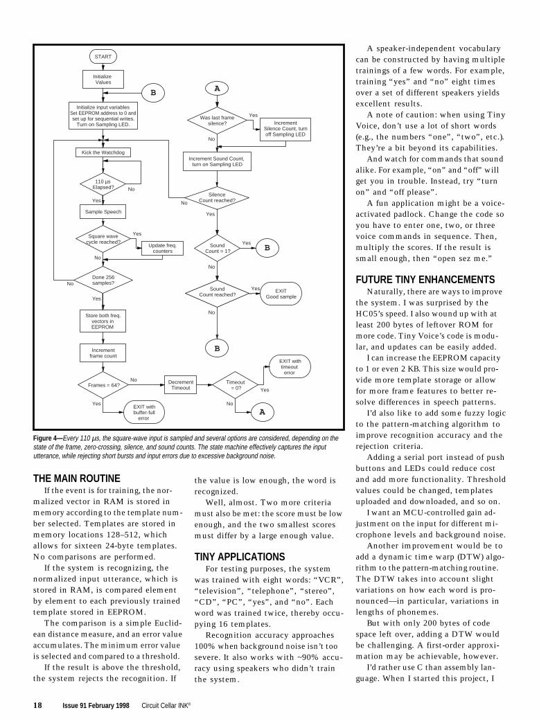
occurs, the input routine is invoked(see Figure 4). A timer is set up andpolled until 110 µs has elapsed.
An interrupt routine could have beenused to time the samples every 110 µs,
but I was concerned that the overheadto service the interrupt might make itdifficult to complete all the paths inthe input routine within 110 µs.
Once the time elapses, the inputsquare wave is sampled. If the signchanges from the previous measure-ment, one of the two frequency bytesis updated.
The threshold limit is set to six. Inother words, if the pulse (positive ornegative) is greater than six samples(roughly corresponding to 1.5 kHz), the“high” frequency byte is incrementedby one. If it’s less than six, the “low”frequency byte is incremented.
The rest of the routine is basicallya state machine that uses speech activ-ity as an input to determine a utterancebounded by silence. At each rising orfalling edge, another byte counts thezero crossings.
After 256 samples, a frame counteradvances and several tests are made. Ifthe frame counter is greater than 64, theinput buffer is filled (i.e., you spoke toolong) or there is too much backgroundnoise, and an error is generated.
Otherwise, a timeout value is decre-mented and tested. This setup enablesthe routine to exit if too much timeelapses before any sound is input.
If the buffer isn’t full or a timeouthas not occurred, then it tests the zero-crossing counter. Too low a valuesignifies silence, and a silence counteris incremented.
Otherwise, a sound-activity counteris incremented. If the sound-activityvalue is above a certain threshold andthe silence value is high enough, theroutine exits with a valid data sample.
TIME NORMALIZATIONWords vary in length. But for this
algorithm to work, the lengths mustbe normalized to a fixed value.
Each sample consists of two bytessampled over one frame of 256 samples.The unnormalized data in the first128 bytes of the EEPROM is normal-ized to a set of 12 vectors in main RAM.
The vector in RAM is built up,element by element, by down- or up-sampling the raw data in EEPROM.Since there are two elements per fea-ture, a template has a fixed memorylength of 24 bytes.
In Recognition mode, the speech issampled and analyzed. The On LED isactivated, and the user is prompted tosay a previously trained command. Asbefore, the Sampling LED is lit duringspeech and off during periods of silence.
The input is compared to the tem-plates in memory and a decision made.If recognition is successful, the resultis displayed on the four LEDs in binary.
When Reset is pressed, Stop modeis entered and the system is ready toaccept a push-button command. Previ-ously trained commands are not erased.
When an error occurs, the Error LED(D1) is lit and the error code is displayedin binary using the same four LEDsthat display the template index number.After ~2 s, the LEDs go off and thesystem enters Stop mode.
The error codes—Time Out, BufferFull, and Not Recognized—are definedin the header file.
After Train or Recognize is pressed,the system waits for valid speech input.If no input occurs after ~6.5 s, thesystem enters the Stop condition andthe Time Out error code is displayed.
On the other hand, if the length ofthe utterance is longer than 1.6 s, thesystem enters the Stop mode and theBuffer Full error is displayed.
The Not Recognized error code isdisplayed if the input utterance doesn’tmatch a stored template. The systemthen enters Stop mode and waits fornew input.
TINY ALGORITHMSThe software for Tiny Voice was
written entirely in assembly. There isa total of eight routines.
Photo 1— My prototype wasbuilt on a 3″× 3″ breadboardand is powered off a 9-Vbattery. The only ICs are the68HC705J1 processor, LM358dual-operational amplifier, the4096-bit FM24C04 FRAM serialmemory, and a 78L05 5-Vregulator.
18 Issue 91 February 1998 Circuit Cellar INK®
THE MAIN ROUTINEIf the event is for training, the nor-
malized vector in RAM is stored inmemory according to the template num-ber selected. Templates are stored inmemory locations 128–512, whichallows for sixteen 24-byte templates.No comparisons are performed.
If the system is recognizing, thenormalized input utterance, which isstored in RAM, is compared elementby element to each previously trainedtemplate stored in EEPROM.
The comparison is a simple Euclid-ean distance measure, and an error valueaccumulates. The minimum error valueis selected and compared to a threshold.
If the result is above the threshold,the system rejects the recognition. If
the value is low enough, the word isrecognized.
Well, almost. Two more criteriamust also be met: the score must be lowenough, and the two smallest scoresmust differ by a large enough value.
TINY APPLICATIONSFor testing purposes, the system
was trained with eight words: “VCR”,“television”, “telephone”, “stereo”,“CD”, “PC”, “yes”, and “no”. Eachword was trained twice, thereby occu-pying 16 templates.
Recognition accuracy approaches100% when background noise isn’t toosevere. It also works with ~90% accu-racy using speakers who didn’t trainthe system.
A speaker-independent vocabularycan be constructed by having multipletrainings of a few words. For example,training “yes” and “no” eight timesover a set of different speakers yieldsexcellent results.
A note of caution: when using TinyVoice, don’t use a lot of short words(e.g., the numbers “one”, “two”, etc.).They’re a bit beyond its capabilities.
And watch for commands that soundalike. For example, “on” and “off” willget you in trouble. Instead, try “turnon” and “off please”.
A fun application might be a voice-activated padlock. Change the code soyou have to enter one, two, or threevoice commands in sequence. Then,multiply the scores. If the result issmall enough, then “open sez me.”
FUTURE TINY ENHANCEMENTSNaturally, there are ways to improve
the system. I was surprised by theHC05’s speed. I also wound up with atleast 200 bytes of leftover ROM formore code. Tiny Voice’s code is modu-lar, and updates can be easily added.
I can increase the EEPROM capacityto 1 or even 2 KB. This size would pro-vide more template storage or allowfor more frame features to better re-solve differences in speech patterns.
I’d also like to add some fuzzy logicto the pattern-matching algorithm toimprove recognition accuracy and therejection criteria.
Adding a serial port instead of pushbuttons and LEDs could reduce costand add more functionality. Thresholdvalues could be changed, templatesuploaded and downloaded, and so on.
I want an MCU-controlled gain ad-justment on the input for different mi-crophone levels and background noise.
Another improvement would be toadd a dynamic time warp (DTW) algo-rithm to the pattern-matching routine.The DTW takes into account slightvariations on how each word is pro-nounced—in particular, variations inlengths of phonemes.
But with only 200 bytes of codespace left over, adding a DTW wouldbe challenging. A first-order approxi-mation may be achievable, however.
I’d rather use C than assembly lan-guage. When I started this project, I
Figure 4— Every 110 µs, the square-wave input is sampled and several options are considered, depending on thestate of the frame, zero-crossing, silence, and sound counts. The state machine effectively captures the inpututterance, while rejecting short bursts and input errors due to excessive background noise.
START
Initialize Values
Initialize input variablesSet EEPROM address to 0 andset up for sequential writes.
Turn on Sampling LED.
110 µsElapsed?
B
Sample Speech
Square wavecycle reached?
Done 256samples?
Store both freq.vectors inEEPROM
Update freq.counters
Was last framesilence?
SilenceCount reached?
Incrementframe count
IncrementSilence Count, turnoff Sampling LED
Increment Sound Count, turn on Sampling LED
Frames = 64?
EXIT withbuffer-full
error
SoundCount = 1?
Kick the Watchdog
SoundCount reached?
EXITGood sample
A
Timeout= 0?
EXIT withtimeout
error
A
B
B
DecrementTimeout
No
Yes
No
Yes
Yes
Yes
No
No
Yes
Yes
Yes
Yes
Yes
No
No
No
No
No

Circuit Cellar INK® Issue 91 February 1998 19
I R S401 Very Useful402 Moderately Useful403 Not Useful
SOURCES
68HC705J1AMotorolaMCU Information LineP.O. Box 13026Austin, TX 78711-3026(512) 328-2268Fax: (512) 891-4465
FM24C02Ramtron Intl. Corp.1850 Ramtron Dr.Colorado Springs, CO 80921(719) 481-7000Fax: (719) 481-9294www.ramtron.com
C CompilerByte Craft Limited421 King St. N.Waterloo, ONCanada N21 4E4(519) 888-6911Fax: (519) 746-6751www.bytecraft.com
ARM710M, SM8500Sharp Electronics Corp.Microelectronics Gr.5700 NW Pacific Rim Blvd., Ste. 20Camas, WA 98607(206) 834-2500Fax: (206) 834-8903www.sharpmeg.com
Brad Stewart is currently the producttechnical manager for RISC processorsat Sharp Electronics. He also servedas technical director for IPI, whichspecialized in voice-recognition andspeech-compression software, andvice president of Covox, which spe-cialized in multimedia products. Youmay reach Brad at [email protected] [email protected].
REFERENCES
B. Georgiou, “Give an Ear to YourComputer,” BYTE, 56–91, June,1978.
Motorola, MC68HC05J1A Techni-cal Data Manual, 1997.
Sharp Electronics, SM8500 User’sGuide, 1997.
B.C. Stewart and S. Sidman, “Designand Use of Voice Recognition inEmbedded Applications,” Paperpresented at ESC East, Boston,MA, 1997.
knew squeezing this functionality into1200 bytes would be tough. So, a high-level language was out of the question.
Since then, I’ve had the opportunityto try out a C compiler from ByteCraft. The good news is, it generatessmall enough code. The bad news: Iwish I’d used it earlier.
And as a final wish, I would like touse a different processor. Of all theseimprovements, this one is probablythe best. You can now get equivalentMCUs with built-in ADCs, whichwould provide more elaborate signalprocessing and better noise rejection.
One of the best candidates for alow-cost system is the Sharp SM85008-bit MCU. It has almost everything youneed for an embedded voice-commandsystem, including a 10-bit ADC (8 chan-nels) and an 8-bit DAC, which is usefulfor voice feedback and verification.
The SM8500 features SIO and UARTports to communicate with othersystem devices, 2 KB of internal RAM,as well as internal ROM and the abilityto access external ROM or RAM. Italso offers 80+ I/O pins for keypad anddisplay interfacing, hardware multiplyand divide, and a 250-ns instructioncycle time. And, it costs under $3.
If you’re willing to spend a bitmore, then a new level of performancemay be realized. New 32-bit RISCMCUs are becoming available in thesub $15 or even sub $10 range.
For example, the Sharp ARM710MRISC processor, running at a conser-vative 16 MHz, performs a completeFFT-Mel-Cepstrum analysis usingonly 50% of the processor’s resources.
With the ability of RISC processorsto address large amounts of memory,you have the ingredients to put to-gether a dictation system like the oneI’m using now. And, it can run off acouple pen-light batteries! I
SOFTWARE
Source code (tinyvoice.zip) for thisarticle may be downloaded fromthe Circuit Cellar Web site.

20 Issue 91 February 1998 Circuit Cellar INK®
Building an EmbeddedWeb Server from Scratch
FEATUREARTICLE
Richard Ames
wTired of surfing?Ready to make somewaves of your own?Richard demonstrateshow to implementyour own embeddedWeb server—fromcreating a baseTCP/IP application towriting interactiveHTML forms.
eb surfing maybe an absorbing and
potentially educationalactivity, but there’s some-
thing about it that’s just so…passive.Sometimes, you yearn to not onlypartake of the networked wonders ofthe world, but to add to them as well.
So, you take this opportunity tocreate your own Web page, completewith scanned images of your pets, alocal map highlighting your favoritepizza parlors, and links to magneticmedia duplicators.
But, the hit counter isn’t increment-ing quickly. And besides, the page isstored on some massive drive in somecomputer you’ve never seen before.
Being a hands-on sort of person,you’re ready for the next step. It’s timeto put together your own embeddedWeb server from scratch.
Your own Web server can do a lotmore than serve up text and GIFs. Itcan also provide a way to monitor andcontrol an embedded system.
Since powerful Web browsers aregiven away free today, there’s a greatopportunity to add a graphical frontend to control your embedded systemand display status or supply controlparameters in a user-friendly manner.
Fortunately, the protocol that de-scribes the operations of a Web server
Figure 1 —Whenclients and serversare written using theBSD Socketsinterface, these arethe typical functioncalls made totransfer information.
is rather straightforward. The mostrecent version of the formal specifica-tion HTTP 1.1 is contained in RFC2068. The preceding version—HTTP1.0—is simpler to implement andwidely supported.
The example I present here followsthe earlier standard. But first, let mebriefly summarize Web-server operation.
SERVER OPERATIONIn a typical client/server system, the
client establishes a connection with theserver, submits a request to the server,interprets the server’s response, andthen sends further requests or closesthe connection if it’s no longer needed.
A Web browser is a client applicationthat establishes a connection with aWeb server, requests a resource fromthe server, reads the information thatthe server sends, displays it using thebuilt-in formatting information, andthen closes the connection.
If the page just loaded contains refer-ences to multimedia resources thathaven’t been loaded yet, then additionalconnections are established to readand display this information.
This action continues until all theresources on a Web page are retrieved.At this point, the system waits foryou to click on a new resource, whichleads to a server being contacted torequest the new resource and thecycle starts anew.
To implement your own Web server,you need to create your own TCP/IPapplication that runs on top of a TCP/IP stack. The application establishesthe connection, reads and writes data,and closes the connection using func-
Server Client
socket()
connect()
write()
read()
close()
socket()
bind()
listen()
accept()
read()
write()
close()

Circuit Cellar INK® Issue 91 February 1998 21
tions provided by the stack. (Refer to“TCP/IP in Embedded Systems” [INK79] for an overview of stacks in em-bedded systems.)
Although the RFCs suggest thegeneral form and the capabilities to besupplied by the interface between anetwork application and TCP/IP stack,they don’t fully specify the Applica-tion Program Interface (API).
A number of APIs have been estab-lished, but by far the most common isthe BSD Sockets interface, which isprovided by BSD releases of the Unixoperating system. A close relative, theWinSock interface, is used for Windowsnetworking applications.
I’ll use the BSD Sockets interface toillustrate a sample Web-server applica-tion because it is well known andwidely available. Of course, my codemay need slight adaptation to work withother TCP/IP-stack implementations.
Figure 1 illustrates a typical sequenceof BSD Sockets functions that arecalled by server and client applicationsin a network transfer. They act as aroad map to the Web-server code inListing 1.
GETTING A HANDLE ON THINGSThe Web server’s first task is to
indicate its interest in receiving TCPsegments directed to port 80, which isthe default port for an HTTP server.Under BSD Sockets, four functioncalls are made to set this up.
The first step allocates a socket forthe server to use. A socket is a datastructure that maintains informationon a network connection.
The prototype for the function is:
int socket(int domain, inttype, int protocol);
The first parameter is the communi-cations domain, which in this case isPF_INET, indicating that I want to workwith the Internet protocol family. Otherdomains can be specified for othercommunications families (e.g., ISO).
The next parameter is the sockettype, which I specified as SOCK_STREAM, indicating that I want reli-able bytestream service (i.e., TCP).SOCK_DGRAM would be specified forUDP service.
#include <stdio.h>#include <sys/types.h>#include <sys/socket.h>#include <netinet/in.h>#include "romfile.h"#define HDR "HTTP/1.0 200 OK\r\n"#define HDRHTML "Content-type: text/html\r\n"#define HDRJPEG "Content-type: image/jpeg\r\n"#define DEFAULTRESOURCE "index.html"main() char buf[500]; /* holds incoming request, outgoing response */ char defaultresource[] = DEFAULTRESOURCE; char resourcename[80]; /* holds name of requested resource */ char *filename; /* pointer to requested resource */ char *extension; /* ptr to extension for requested resource */ int remSize; /* holds size of address structure */ int retcod; /* general purpose return code */ int s; /* handle to listening socket */ int s2; /* handle to socket being serviced */ long filelen; /* size of requested resource */ struct sockaddr_in locAddr; /* addr struct for local address */ struct sockaddr_in remAddr; /* addr struct for remote address */ RFHTYPE rfhandle; /* handle for rom file */ printf("Sample Web Server v0.0\n"); s = socket(AF_INET, SOCK_STREAM, 0); /* create listening socket */ if (s < 0) printf("Error opening socket\n"); return -1; memset((void *) &locAddr, 0, sizeof(locAddr)); locAddr.sin_family = AF_INET; locAddr.sin_addr.s_addr = htonl(INADDR_ANY); locAddr.sin_port = htons(80); retcod = bind(s, (struct sockaddr *) &locAddr, sizeof(locAddr)); if (retcod < 0) printf("Error binding socket\n"); close(s); return -1; retcod = listen(s, 5); if (retcod < 0) printf("Error in listen\n"); close(s); return -1; while (1) remSize = sizeof(remAddr); s2 = accept(s, (struct sockaddr *) &remAddr, &remSize); if (s2 < 0) printf("Error in accept\n"); close(s); return -1; retcod = read(s2, buf, sizeof(buf)); /* read request */ if (retcod >= 0) buf[retcod] = 0; /* change to null terminatd str */ printf("%s\n", buf); /* display request for debug */ write(s2, HDR, strlen(HDR)); /* write first response line */ sscanf(buf, "GET %s", resourcename); /* find resource */ filename = defaultresource; /* use this resource for deflt */ if (strcmp("/", resourcename) != 0)/* is this default request? */ filename = resourcename + 1; /* no, skip past initial '/' */ extension = filename; /* isolate extension */ while ((*extension) && (*extension != '.')) extension++; if (strcmp(".html", extension) == 0) /* write type */ write(s2, HDRHTML, strlen(HDRHTML)); else if (strcmp(".jpg", extension) == 0) write(s2, HDRJPEG, strlen(HDRJPEG));
Listing 1 — This code implements a minimal Web server that can be set up to deliver ROMed Web pages.This example compiles and runs under Linux, and can be easily adapted for other environments.
(continued)

22 Issue 91 February 1998 Circuit Cellar INK®
blocks until a connection is establishedand then returns a handle to a newsocket associated with the client thatconnected.
The original socket continues tocollect subsequent clients that wantto connect to port 80. A return valueof –1 indicates an error.
ITERATIVE VS. CONCURRENTWhen a client establishes a connec-
tion with a server, the server creates adata structure that holds the state of theconnection until the connection closes.The server then listens for and respondsto client requests until one side or theother indicates that the connectionshould be closed.
What happens if another client con-tacts the server while the first clientis being served? The outcome dependson the design of the server.
In an iterative server, the secondclient’s requests are ignored until theconnection with the first client closes.
In a concurrent server, the code thatservices a connection is set up as a task,and this task is launched every time aconnection is established. So, a concur-rent server can serve more than oneconnection at once, assuming that thesystem software supports multitasking.
For this demonstration, I take theapproach of an iterative server. Thisapproach isn’t the most common for aWeb server, but it will do, especiallysince I expect the server to only ser-vice one client at a time.
Other clients that request servicesare forced to wait until a previousrequest has been fulfilled. This scenariois often quite workable but doesn’tmake sense for a large-scale server.
The final parameter can be used tofurther specify the protocol, but forInternet bytestream service, a 0 suffices.socket() returns a handle to thesocket or –1 to indicate an error.
This seems like a roundabout wayof indicating that you want a handleto a socket that talks TCP. However,the BSD Sockets interface is used formore than applications running over aTCP/IP stack.
There’s a whole world of protocols—old, current, and yet to be defined—that can be coupled to an applicationthrough this interface. The protocoldoesn’t even need to be a network proto-col. For example, the Unix domainprotocol permits interprocess commu-nication within the same system.
Once you have a handle to a socket,you need to specify the port at whichyou’re listening for incoming informa-tion. This task is accomplished via acall to the bind() function:
int bind(int s, struct sockaddr*my_addr, int addrlen);
The first parameter is the handle tothe socket that was returned earlier.The second parameter passes a pointerto a socket address structure thatspecifies the local IP address and portnumber for this connection.
For Internet addresses, the sock-addr_in structure is used, which con-tains fields for the address family, IPaddress, and port number. You clear thestructure and then fill in these valuesbefore passing a pointer to the structurein the call to bind(). The port-numberfield is a two-byte value that shouldbe expressed in network byte order,which is Big Endian.
To make the code portable, the util-ity function htons()translates betweenthe host’s native format and networkbyte order before saving the value inthe structure. The constant INADDR_ANY indicates that this socket shouldaccept connections from any of thesystem’s network interfaces. This four-byte IP address also needs to be trans-lated by the htonl() utility functionto put it in network byte order beforestoring the value in the structure.
The last parameter in the call issimply the size of the sockaddr_in
structure, another indication of theflexible design of the socket’s interface.It returns –1 if there is an error.
Now, I have a socket associated witha port. The next step is to put the socketinto the listen state, so it’s ready toservice incoming requests for connec-tions to port 80. This task is done with acall to listen:
int listen(int s, int backlog);
Here, I simply specify the socket anda backlog value, which indicates thenumber of connections that will beheld in a queue awaiting service. Anerror is indicated by a –1 return value.
Finally, I make a call to accept aconnection:
int accept(int s, struct sockaddr*addr, int *addrlen);
Here again, I pass a socket handle andthen a pointer to an address structure,followed by a pointer to the size of theaddress structure.
In this case, the accept() functionfills in the IP address and port numberof the remote system that is establish-ing a connection on the socket in theaddress parameter. The applicationtherefore knows a little about theremote system requesting services whenthe function returns.
The address-length parameter shouldcontain a pointer to an integer with thelength of the address structure. Onreturn from accept(), this parametercontains the length of the addressstructure that was filled in.
For Internet protocols, this valuedoesn’t change. The accept() function
Listing 1 —continued
rfhandle = romfileopen(filename); /* open local resource */ filelen = romfilelen(rfhandle); /* determine size */ sprintf(buf, "Content-length: %d\r\n\r\n", filelen); write(s2, buf, strlen(buf)); /* write size */ while (1) /* write out resource */ if ((retcod = romfileread(rfhandle, buf, sizeof(buf))) > 0) write(s2, buf, retcod); else break; romfileclose(rfhandle); /* close resource */ close(s2); /* close connection */ return 0;

24 Issue 91 February 1998 Circuit Cellar INK®
Photo i —The code of Listing i produces this minimalWeb page. It looks good as 109,208 pixels.
<!DOCTYPE HTML PUBLIC "-//IETF//DTD HTML 2.0//EN"><HTML><HEAD><TITLE>Embedded Web Server</TITLE></HEAD>
<BODY><H1>Features</H1><UL> <LI>Intuitive Interface <LI>Contemporary Styling <LI>Small Footprint</UL><P>One paragraph is all we have ROM for.</BODY>
</HTML>
Listing i —A minimal Web page can be rather short. Here are 274 bytes worth.
Basic HTMLHypertext Markup Language (HTML) is the formatting language that
transforms plain text into the attractive Web pages that fill the Internet.Creating effective HTML pages for an embedded system requires an extrameasure of skill because you need to make the most of a limited set ofresources. We all know how graphic images can eat up memory, so it makessense to keep GIF images to a minimum and make the most of the otherformatting features.
The formatting information is included in the document via tags thatappear between angled brackets (e.g., <TT>, which specifies a teletype-likefont). The syntactic rules for HTML can be inferred by reviewing examples,and RFC 1866 can be consulted for the specifics of HTML V.2.0.
Much of the formatting is specified by a pairing of a start tag and an endtag, such as <I>italic</I>, where the slash indicates the end of italicfont. Some tags stand alone though. For example, <HR> creates a horizon-tal line across the page.
Tags may also contain attributeswhich may further specify format-ting information. Listing i showsthe basic form of a document andwhen displayed appears as Photo i.In most cases, the browser treatsall white space in the same way,allowing you to format the infor-mation so it is easier to follow.
The document is made up ofHEAD and BODY sections. A TITLEmust be present in the HEAD sec-tion. This title is typically dis-played in a title bar on the Webbrowser and is also stored in abrowser’s list of saved links. TheBODY section contains the con-tents of the page. Table i listssome formatting features that canliven up this section.

26 Issue 91 February 1998 Circuit Cellar INK®
Now is the time for the server toread() a request from the server. Theread() function is similar to a file read:
int read(int s, char *buf,int count);
The application specifies the sockethandle, a pointer to a buffer that storesthe incoming data, and the buffer size.When the function returns, the numberof bytes that were read is returned.
This value may be less than therequested amount of information, andthe application should continue toissue calls to read from the connectionif the application-level transactionsyntax indicates that more informationis expected.
TCP acts like a pipeline deliveringa bytestream, and the read() functiondelivers information as soon as it isavailable. However, the applicationdeveloper should be aware that theremay be more in the pipeline, especiallyif the buffer being read is large.
So, let’s assume now that the serverprogram is running on your Web server,which you set up with the IP addressof 192.168.173.15. You fire up yourfavorite Web browser and request theURL <http://192.168.173.15/>.
Photo 1 —Using HTML form tags, we achieve some-thing very much like a traditional graphical user inter-face. Listing 4 contains the code to instruct the browserto generate this image.
Table i —These common formatting tags help spice up the text on your pages.
<H1>–<H6> Headers of increasingly less emphasis<P> Starts new paragraph, leaving a blank space to separate from the previ-
ous paragraph. A </P> end tag is optional.<PRE> Preformatted text. Preserves line breaks in the original text. Usually, line
breaks are ignored and the text is flowed to fit in the browser’s window.<UL> Starts unordered list, typically presented as a series of bulleted items.
Within this section, the <LI> tag starts a list item.<OL> Starts ordered list, similar to above, but with numerals<EM> Starts emphasis, often expressed as italics
<STRONG> Starts strong emphasis, usually in bold<BR> Forces line break. An end tag is not needed.<HR> Inserts horizontal line<IMG> Inserts graphical image
A number of utilities—commercial and otherwise—can be used to sim-plify the creation of HTML text. Most browsers have a View Source optionthat lets you to see how a particularly neat feature of a Web page has beenimplemented. Beware of incorporating nonstandard HTML into your ROM,though.
Circuit Cellar INK® Issue 91 February 1998 27
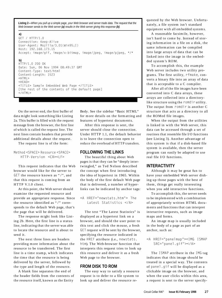
Listing 2 —When you pull up a simple page, your Web browser and server trade data. The request that theWeb browser sends to the Web server (a) results in the Web server giving this response (b).
GET / HTTP/1.0Connection: Keep-AliveUser-Agent: Mozilla/3.01(Win95;I)Host: 192.168.173.15Accept: image/gif, image/x-bitmap, image/jpeg, image/pjpeg, */*
HTTP/1.0 200 OKDate: Sun, 06 Nov 1994 08:49:37 GMTContent-Type: text/htmlContent-Length: 1523<HTML><HEAD><TITLE> Sample Embedded Web Page </TITLE>[the rest of the contents of the default page]</HTML>
a)
b)
On the server end, the first buffer ofdata might look something like Listing2a. This buffer is filled with the requestmessage from the browser, the first lineof which is called the request line. Thenext lines contain headers that provideadditional details about the request.
The request line is of the form:
Method <SPACE> Resource <SPACE>HTTP-Version <CR><LF>
This request indicates that the Webbrowser would like for the server toGET the resource known as “/”, andthat this request is coming from anHTTP V.1.0 client.
At this point, the Web server shouldexamine the requested resource andprovide an appropriate response. Sincethe resource identified as “/” corre-sponds to the default Web page, that’sthe page that will be delivered.
The response might look like List-ing 2b. Here, the first line is a statusline, indicating that the server was ableto locate the resource and is about tosend it.
The next three lines are headersproviding more information about theresource to be transferred. The firstline is a time stamp, which indicatesthe time that the resource is beingdelivered by the server, followed bythe type and length of the resource.
A blank line separates the end ofthe header fields from the contents ofthe resource itself, known as the Entity
Body. See the sidebar “Basic HTML”for more details on the formatting andfeatures of hypertext documents.
After this response is sent, theserver should close the connection.Under HTTP 1.1, the default behavioris to leave the connection open toreduce the overhead of HTTP transfers.
FOLLOWING THE LINKSThe beautiful thing about Web
pages is that they can be “deeply inter-twingled,” as Ted Nelson describedthe concept when first introducingthe idea of hypertext in 1965. Withinthe body of the first default Web pagethat is delivered, a number of hyper-links can be indicated by anchor tags:
<A HREF="newstats.htm"> TheLatest Statistics </A>
The text “The Latest Statistics” isdisplayed as a hypertext link on abrowser, and should the user point tothis text and click the mouse, a freshGET request will be sent by the browser,specifying the resource indicated inthe HREF attribute (i.e., newstats.htm). The Web-browser function thatinterprets this request tries to look upthis resource and deliver it as a freshWeb page to the browser.
FROM DISK TO ROMThe easy way to satisfy a resource
request is to defer to a file system tolook up and deliver the resource re-
quested by the Web browser. Unfortu-nately, a file system isn’t standardequipment with all embedded systems.
A reasonable facsimile, however,isn’t hard to come by. Instead of stor-ing information in a file on a disk, thesame information can be compiledinto large arrays of data that can belinked into the image in the embed-ded system’s ROM.
To accomplish this, the exampleWeb server includes two utility pro-grams. The first utility, rfmake, con-verts a binary file into an array of datathat is acceptable to a C compiler.
After all of the file images have beenconverted into C data arrays, thesearrays are collected into a directory-like structure using the romdir utility.The output from romdir is another Cstructure that acts as a directory to allthe ROMed file images.
When the output from the utilitiesis linked in with the Web server, thisdata can be accessed through a set ofroutines that resemble file I/O functions(see Listing 3). Another advantage ofthis system is that if a disk-based filesystem is available, then the serverprogram can easily be adapted to usereal file I/O functions.
INTERACTIVITYAlthough it may be great fun to
have your embedded Web server dish-ing up those pages with the best ofthem, things get really interestingwhen you add interactive functions.
To accomplish this, the server needsto be implemented with a combinationof appropriately written HTML docu-ments and functions that can interpretinteractive requests, such as imagemaps and forms.
An image map is usually includedin the body of a page as part of ananchor, such as:
<A HREF="panelmap"><IMG ISMAPSRC="panel.gif"></A>
The ISMAP attribute in the IMG tagindicates that this image should betreated in a special way. The contentsof panel.gif will be displayed as aclickable image on the browser, andwhen the user clicks within this area,a request is sent to the server specify-

28 Issue 91 February 1998 Circuit Cellar INK®
I R S404 Very Useful405 Moderately Useful406 Not Useful
SOFTWARE
The rfmake and romdir utilitiesdiscussed in this article are avail-able on the Circuit Cellar Web site.
Listing 4 —In the second line of this section of HTML, TYPE=TEXT specifies that the form’s input willcome as a text box, NAME="LiteOn" is the variable name associated with the input, SIZE=10entails that 10 spaces will be available in text box, and Lights On is the label to be displayed besidethe box on the form. See Photo 1 for the end result.
<FORM ACTION="control" METHOD="POST"> <INPUT TYPE=TEXT NAME="LiteOn" SIZE=10>Lights On <INPUT TYPE=TEXT NAME="LiteOff" SIZE=10>Lights Off <INPUT TYPE="submit" NAME="Save"></FORM>
Listing 3 —These function prototypes form the link between the Web server and a file system. They havebeen defined to make it easy to use either a disk- or memory-based file system.
RFHTYPE romfileopen(char *romfilename);long romfilelen(RFHTYPE handle);int romfileread(RFHTYPE handle, char *buf, int bufsize);int romfileclose(RFHTYPE handle);
ing the offset into the bitmap wherethe mouse click occurred.
The server may see a request forpanelmap?12,4, which indicates thatthe user clicked inside this area at apoint 12 pixels from the left edge and 4pixels down from the top of the image.
By supplying a routine on the serverthat interprets location information,the system recognizes the object auser points to and responds appropri-ately. So, clicking on a darkened win-dow in an image of a house mightcommand a home controller to turnon the lighting in this area.
To obtain full style points, theserver could update the image withone that shows the window being lit.
Form submission is another tech-nique that can be used to send infor-mation to a server, providing many ofthe familiar dialog box tools, such astext boxes, check boxes, radio buttons,and lists. These features start with aFORM tag in an HTML document.
Listing 4 presents an example of aform with two text boxes and a submitbutton. The second line refers to thefirst text box. The fourth line in theform definition defines the submit but-ton, which is needed whenever thereis more than one input in a form.
The user can type any text stringinto the boxes for the time at which thehome controller should turn the lightson and off. When the user clicks on thesubmit button, the home-control Webserver is sent the request:
control?LiteOn="7:00p"; LiteOff="9:30p"
Photo 1 displays this interface.Again, an appropriate routine needs
to be provided on the server to interpretthis information and take appropriateaction. The server should also generate apage that tells the user that the com-mand was successfully processed.
ERROR HANDLINGIn a number of situations, the Web
server may not be able to respond to arequest. The user may have typed in arequest for a resource the server hasnever heard of, or the user may haveused an interactive control to submitinformation the server won’t accept.
When everything is in order, theserver sends the string “200 OK”response as part of the status line forthe response.
Additional three-digit codes thatare suitable for other conditions thatmight arise are divided into a series ofrelated responses.
Codes in the 100 series are infor-mational, the 200 series indicatessuccess, the 300 series indicates aneed for redirection, and the 400 and500 series are for client and servererrors, respectively.
For example, a request for an un-known resource could generate a sta-tus line containing “404 Not Found”.In the response, the Entity Body couldcontain HTML text to further explainthat the resource couldn’t be found onthis server.
ON YOUR OWNOf course, this discussion just
begins to describe the sorts of capa-bilities that might be implemented onan embedded Web server.
Additional information on HTMLand HTTP is available online andfrom a library of ever thicker books,and there’s a variety of software toolsthat do everything from verifying thesyntax of an HTML page to providinga turn-key server.
Now you can sleep well, knowingyour home page could be served upfrom a networked controller living ina shoebox under your bed. I
REFERENCES
S. Berners-Lee, R. Fielding, and H.Nielsen, Hypertext Transfer Proto-col—HTTP/1.0, RFC 1945, 1996.
T. Berners-Lee and D. Connolly,Hypertext Markup Language—2.0, RFC 1866, 1995.
R. Fielding, J. Gettys, J. Mogul, H.Frystyk, and T. Berners-Lee, Hyper-text Transfer Protocol—HTTP/1.1,RFC 2068, 1997.
T.H. Nelson, Computer Lib/DreamMachines, Tempus Books, Red-mond, WA, 1977 (Reprinted byMicrosoft Press).
D. Raggett, HTML Tables, RFC1942, 1996.
W.R. Stevens, Unix Network Pro-gramming, 1, Prentice-Hall, Engle-wood Cliffs, NJ, 1998.
Richard Ames is a staff engineer atU.S. Software. He finds that workingwith networking software allows himto gather more computers around himthan the average engineer. You mayreach Richard at [email protected].

30 Issue 91 February 1998 Circuit Cellar INK®
Integrating Windows NT 4.0into a TCP/IP Environment
FEATUREARTICLE
Bill Payne
iBill needs to connectWindows NT stationsinto an existingTCP/IP network, butMicrosoft gave theDomain NameServer its ownpersonal twist. Afterreviewing theprotocols, he showshow to get Windowsand Unix to talk.
was recentlyinvolved in a large-
scale project in whichI integrated Windows
NT 4.0 servers and workstations intoan existing TCP/IP network. Thenetwork comprised multiple Unix,IBM mainframe, PC, and DEC Alpha-based hosts.
In addition, approximately 3000clients were to be upgraded from Win-dows 3.11 to Windows 95 and Win-dows NT 4.0 Workstation.
The network used the DynamicHost Configuration Protocol (DHCP),an open industry standard designed toreduce the complexity of managing aTCP/IP network.
Every computer and resource on aTCP/IP network must be given a uniqueIP address and computer name. DHCPassigns a client an IP address from a poolof addresses when it starts up. Thisenables the IP addresses to be managedfrom one central point on the network.
The network also uses the DomainName System (DNS) for name-to-IPaddress resolution. Cisco routers wereimplemented to segment the networkinto smaller manageable sections.
After the initial installation of theWindows NT 4.0 servers, we beganhaving problems with the addressresolution process on various clients
throughout the network. And, theproblem wasn’t DHCP. It workedproperly, assigning IP addresses toclient workstations as requested.
But, if we used a command thattried to resolve a name to an IP address,we had problems. Sometimes the namewould resolve, but not necessarily.
We also began seeing a lot of trafficon the segments that had been createdwith the routers. One thing stoodout—if the name to be resolved wason the same segment as the clientissuing the query, it worked.
After many hours of going throughtraces from a network sniffer, theproblem was found and corrected. Itturns out that even though DNS is astandard, certain companies give ittheir own personal twist.
Such is the case when interconnect-ing devices that use the enhancementsdeveloped by Microsoft. The problemsdo not manifest themselves untilrouters are added to a network.
Routers in general do not forwardbroadcast messages. The reason forusing routers in the first place is tosegment the network and to isolatetraffic to separate segments.
Windows NT relies on a processcalled Windows Internet Name Service(WINS) for name resolution. Thisservice augments the traditional DNSservice with dynamic name registrationcapabilities and uses the NetBIOSprotocol encapsulated in TCP/IP forcommunication between nodes.
To help you gain an understanding ofthe problem, I first present the basicconcepts of TCP/IP, DNS, and WINSas implemented by Microsoft. Once youhave the nuances down, interconnect-ing systems using TCP/IP in a routednetwork becomes fairly straightforward.
TCP/IPThe Transmission Control Protocol/
Internet Protocol (TCP/IP) suite is astandard set of networking protocols.It was originally developed by theDepartment of Defense and is some-times referred to as the DOD model.
A protocol is an agreed-to set of rulesgoverning the communication of databetween two parties. You could com-pare it to two people trying to com-municate with each other. They must
Circuit Cellar INK® Issue 91 February 1998 31
both speak the same language or notransfer of information occurs.
TCP/IP is a scalable, robust, client-server networking protocol. It connectsdissimilar systems and is the basis ofthe global Internet.
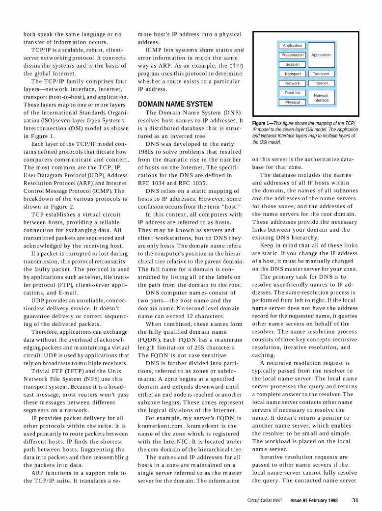
The TCP/IP family comprises fourlayers—network interface, Internet,transport (host-to-host), and application.These layers map to one or more layersof the International Standards Organi-zation (ISO) seven-layer Open SystemsInterconnection (OSI) model as shownin Figure 1.
Each layer of the TCP/IP model con-tains defined protocols that dictate howcomputers communicate and connect.The most common are the TCP, IP,User Datagram Protocol (UDP), AddressResolution Protocol (ARP), and InternetControl Message Protocol (ICMP). Thebreakdown of the various protocols isshown in Figure 2.
TCP establishes a virtual circuitbetween hosts, providing a reliableconnection for exchanging data. Alltransmitted packets are sequenced andacknowledged by the receiving host.
If a packet is corrupted or lost duringtransmission, this protocol retransmitsthe faulty packet. The protocol is usedby applications such as telnet, file trans-fer protocol (FTP), client-server appli-cations, and E-mail.
UDP provides an unreliable, connec-tionless delivery service. It doesn’tguarantee delivery or correct sequenc-ing of the delivered packets.
Therefore, applications can exchangedata without the overhead of acknowl-edging packets and maintaining a virtualcircuit. UDP is used by applications thatrely on broadcasts to multiple receivers.
Trivial FTP (TFTP) and the UnixNetwork File System (NFS) use thistransport system. Because it is a broad-cast message, most routers won’t passthese messages between differentsegments on a network.
IP provides packet delivery for allother protocols within the suite. It isused primarily to route packets betweendifferent hosts. IP finds the shortestpath between hosts, fragmenting thedata into packets and then reassemblingthe packets into data.
ARP functions in a support role tothe TCP/IP suite. It translates a re-
mote host’s IP address into a physicaladdress.
ICMP lets systems share status anderror information in much the sameway as ARP. As an example, the pingprogram uses this protocol to determinewhether a route exists to a particularIP address.
DOMAIN NAME SYSTEMThe Domain Name System (DNS)
resolves host names to IP addresses. Itis a distributed database that is struc-tured as an inverted tree.
DNS was developed in the early1980s to solve problems that resultedfrom the dramatic rise in the numberof hosts on the Internet. The specifi-cations for the DNS are defined inRFC 1034 and RFC 1035.
DNS relies on a static mapping ofhosts to IP addresses. However, someconfusion occurs from the term “host.”
In this context, all computers withIP address are referred to as hosts.They may be known as servers andclient workstations, but to DNS theyare only hosts. The domain name refersto the computer’s position in the hierar-chical tree relative to the parent domain.The full name for a domain is con-structed by listing all of the labels onthe path from the domain to the root.
DNS computer names consist oftwo parts—the host name and thedomain name. No second-level domainname can exceed 12 characters.
When combined, these names formthe fully qualified domain name(FQDN). Each FQDN has a maximumlength limitation of 255 characters.The FQDN is not case sensitive.
DNS is further divided into parti-tions, referred to as zones or subdo-mains. A zone begins at a specifieddomain and extends downward untileither an end node is reached or anothersubzone begins. These zones representthe logical divisions of the Internet.
For example, my server’s FQDN iskramerkent.com. kramerkent is thename of the zone which is registeredwith the InterNIC. It is located underthe com domain of the hierarchical tree.
The names and IP addresses for allhosts in a zone are maintained on asingle server referred to as the masterserver for the domain. The information
on this server is the authoritative data-base for that zone.
The database includes the namesand addresses of all IP hosts withinthe domain, the names of all subzonesand the addresses of the name serversfor those zones, and the addresses ofthe name servers for the root domain.These addresses provide the necessarylinks between your domain and theexisting DNS hierarchy.
Keep in mind that all of these linksare static. If you change the IP addressof a host, it must be manually changedon the DNS master server for your zone.
The primary task for DNS is toresolve user-friendly names to IP ad-dresses. The name-resolution process isperformed from left to right. If the localname server does not have the addressrecord for the requested name, it queriesother name servers on behalf of theresolver. The name resolution processconsists of three key concepts: recursiveresolution, iterative resolution, andcaching.
A recursive resolution request istypically passed from the resolver tothe local name server. The local nameserver processes the query and returnsa complete answer to the resolver. Thelocal name server contacts other nameservers if necessary to resolve thename. It doesn’t return a pointer toanother name server, which enablesthe resolver to be small and simple.The workload is placed on the localname server.
Iterative resolution requests arepassed to other name servers if thelocal name server cannot fully resolvethe query. The contacted name server
Application
Presentation
Session
Transport
Network
DataLink
Physical
Application
Transport
Internet
NetworkInterface
Figure 1 —This figure shows the mapping of the TCP/IP model to the seven-layer OSI model. The Applicationand Network Interface layers map to multiple layers ofthe OSI model.

32 Issue 91 February 1998 Circuit Cellar INK®
Earlier Microsoft implementationsof the NetBT protocol relied on broad-casts, local cache, or an LMHOSTS filefor locating resources on the network.
In Windows NT 3.5x and 4.0, aNetBIOS name server was implementedcalled the WINS server. It lets programsquery the DNS namespace by append-ing user-configurable domain suffixesto a NetBIOS name.
NetBT uses a session layer networkservice to perform name-to-IPmapping for name resolution.There are four basic modes thatdetermine how network re-sources are identified and ac-cessed. The name resolutionorder depends on the mode typeand computer configuration.
The B-node mode uses broad-cast messages to resolve NetBIOSnames to IP addresses. This is thedefault mode type for a Windowsresource on a network.
The P-node mode uses point-to-point communications with aWINS name server for name reg-
istration and resolution.The M-node mode first registers with
the name server using broadcasts beforetrying to resolve names by using theB-node mode. If this fails, it switchesto the P-node mode to resolve names.
The fourth mode—the H-node—usesthe WINS name server for both nameregistration and resolution. If the nameserver cannot be located, it switchesback to the B-node mode.
It then continues to poll for a nameserver and switches back to the P-nodemode when one is located. WINSclients (i.e., Windows NT 3.5x and 4.0workstations and servers) are config-ured as H-node devices by default.
PUTTING IT ALL TOGETHERNow that you have a basic under-
standing of the mechanisms involved,let me explain how DNS name resolu-tion works in conjunction with WINSname resolution. This will give thefoundation needed to understand theoriginal problem and see what solutionsare necessary to run Windows NT in amixed network environment.
For this discussion, let’s assumethat Circuit Cellar is running a Win-dows NT 4.0 Server as their Primary
is instructed to only attempt to resolvethe name locally. If it cannot, it returnsa pointer to the next name server inthe DNS tree.
This process continues to walk upthe hierarchical tree until the primarymaster name server for the zone isreached. An error to the requester isreturned if the name cannot be resolvedat this level.
With caching, the local name serverkeeps a copy of the resolver requestanswer in local memory. Thisspeeds DNS performance and easesthe burden on other name servers.
The local name server firstchecks its static mapping infor-mation when a resolver requestarrives. If the answer is not found,the cache is then checked foreither an answer or a pointer tothe name server containing theanswer. This process reduces thenumber of iterative resolutionrequests for the name servers onthe network.
WINSWindows Internet Name Service
(WINS) is a Microsoft-developed nam-ing service. Microsoft recommendsthat their naming service be used inconjunction with DNS. Unlike thestatic naming which is inherent in DNS,WINS offers dynamic naming capability.To understand how WINS works, anunderstanding of both NetBIOS andNetBEUI is necessary.
All Microsoft Windows networkingcomponents rely on NetBIOS, which is asoftware interface and naming conven-tion, not a protocol. It is a set of Appli-cation Programming Interfaces (APIs)which lets applications request servicesfrom lower-level network processes.
All computers and resources within aMicrosoft networking environmentmust be assigned a unique NetBIOSname, which cannot exceed 16 charac-ters. Microsoft allows the first 15characters to be specified by the useror administrator. The sixteenth char-acter of the name is reserved to indi-cate the resource type. Since it is an8-bit field, there are 256 resourcetypes available.
These device names are storedwithin the NetBIOS namespace data-
base. This database is designed as aflat, single-level structure.
A resource is dynamically registeredwith the database when it starts. Thisoccurs when a computer boots, a ser-vice on a server starts, or a user logson to a resource. Names can be regis-tered as either a single owner or as agroup composed of multiple owners.
In 1985, IBM developed a protocolnamed NetBIOS Extended User Interface
(NetBEUI) for programs designed aroundthe NetBIOS APIs. This small protocoldoes not have a networking layer, soit is not routable and cannot be passedbetween segments connected by routers.
NetBEUI was originally designedfor department-sized LANs rangingfrom 20 to 200 computers. It supportsboth connection-oriented and connec-tionless communications.
Its greatest strengths are that it isself-configuring and self-tunable. Itrequires a very small memory overheadin the client and provides for reason-able error detection and correction.
The NetBEUI protocol is the gluethat provides interoperability witholder networking systems, such asMicrosoft LAN Manager and Win-dows for Workgroups 3.11. When youset up shared drives and folders underWindows 3.11, 95, and NT, you areusing the NetBEUI protocol.
Microsoft extended the reach of theNetBIOS programming interface withthe NT products to include the worldof client/server applications in a WANenvironment. This was accomplishedby encapsulating the NetBIOS requestsin TCP/IP packets. This is known asNetBT or NetBIOS over TCP/IP.
DOD Model
Process/Application
Host to Host
Internet
NetworkAccess
TCP/IP Protocols
Telnet FTP LPD NFS Others
TCP UDP
IPICMP
BOOTP ARP RARP
EthernetTokenRing FDDI Others
Figure 2 —Each layer within the DOD model is broken down intoindividual protocols. The protocols in the Transport (Host to Host)layer and the Internet layer are the ones of interest in this article.

34 Issue 91 February 1998 Circuit Cellar INK®
I R S407 Very Useful408 Moderately Useful409 Not Useful
in the TCP/IP properties page. If found,the IP address is returned.
The client then checks the localHOSTS file for the NetBIOS computername. This also only occurs if theproper option has been selected in theTCP/IP properties page. If found, theIP address is returned.
The client ends by querying the DNSserver. If the NetBIOS computer nameis in the database, the IP address isreturned to the requesting host.
In P-node mode, the client first issuesa query to the local WINS server. If thename is found, the IP address is returnedto the requesting host.
Next, the third, fourth, and fifthsteps of the H-node mode protocol areexecuted.
In M-node mode, the client useslocal broadcasts to locate the NetBIOScomputer name. If the name is found,the IP address is returned to the re-questing host.
The client then issues a query tothe local WINS server. If the name isfound, the IP address is returned tothe requesting host. Steps 3, 4, and 5are then executed.
And finally, in B-node mode, theclient uses local broadcasts to locatethe NetBIOS computer name. If thename is found, the IP address is returnedto the requesting host, and the third,fourth, and fifth steps are executed.
PROBLEM RESOLVEDIn a traditional TCP/IP environment
(e.g., Unix), the DNS name-resolutionprocess is fairly straightforward. Thehost addresses to be resolved are inthe HOSTS file on the DNS server.
Networks containing routers do notpresent a problem to a system basedon this older technology. The only nameregistration that occurs if the network
uses DHCP is assigning IP addressesto clients. The drawback to this isthat DNS by its nature is static.
The implementation of the Micro-soft WINS server for NetBIOS computername and IP address resolution providesthe ability to dynamically modify theinformation in the translation database.
Windows NT uses UDP broadcastsas the protocol for NetBIOS (NetBT)name resolution. Unfortunately, UDPbroadcast packets are not usually
forwarded by routers betweennetwork segments.
In addition, the WINS name-resolution process can generate aconsiderable amount of burst traf-fic on a network segment. WINSname resolution in a routed envi-ronment requires either a nameserver of some type on each seg-ment of the network or the use ofstatic database files.
In the case of the company I didthe Windows NT integration for, WINSname servers were established oneach segment of the routed network.
Once the problem is understood, theanswer is fairly simple. The problemis in understanding the processes andhow they interact with each other. I
Domain Controller (PDC). This serveralso has the DNS and WINS servicesrunning on it.
Connected to this server are 20workstations running a combinationof Windows 95 and Windows NT 4.0Workstation. I want to look specificallyat communication between hosts onthis simple network.
The resolution process is startedwhen a host issues a query to resolvea name to an IP address. It can be assimple as issuing the ping com-mand directed at an address suchas janice.circuitcellar.com (pingjanice.circuitcellar.com).
If the name to be resolved isgreater than 16 characters or con-tains a “.”, it is passed on to theDNS name server. If the addressrecord for the host janice is found inthe DNS database, it’s returned tothe host which sent the query.
If the name is not found in theDNS database or the name is a validNetBIOS computer name, the WINSclient performs the NetBIOS computername-to-IP address resolution usingNetBT and WINS.
The first thing the WINS client doesis to determine the mode type it isoperating as: H-node, P-node, M-node,or B-node. The mode type is definedon a Windows NT computer throughthe TCP/IP configuration settings.Each mode type processes the queryin a different manner.
The first step is common to all fournode types. The local NetBIOS namecache is searched for the computername. If found, it returns the IP addressto the host which issued the query. Thefollowing steps are executed if the localcache doesn’t contain the NetBIOScomputer name.
As the first step in the H-nodemode, the client issues a query to thelocal WINS server. If the name isfound, the IP address is returned tothe requesting host.
The client then uses local broadcaststo locate the NetBIOS computer name.If the name is found, the IP address isreturned to the requesting host.
As the third step, the client checksthe local LMHOSTS file for the Net-BIOS computer name. This occurs onlyif the proper option has been selected
Bill Payne has many years’ experienceas a digital design engineer. He is aNovell Master CNE, Novell CertifiedInstructor, and a Microsoft CertifiedTrainer for the NT 4.0 Products. Hemay be reached at [email protected].
REFERENCES
Microsoft, Microsoft Windows NTWorkstation Resource Kit, Red-mond, WA, 1996.
Microsoft, Microsoft Windows NTServer Networking Guide, Red-mond, WA, 1996.
Inside TCP/IP, Second Ed., NewRiders, Indianapolis, IN, 1995.
Novell, DNS and FTP Server In-stallation and Configuration,Orem, UT, 1996–97.
Resolving networkaddresses goes back tothe basics of Windowsnetworking protocol—something originally
designed by IBM in 1985.
Photo courtesy ofSpyglass, Inc.
36 Nouveau PCedited by Harv Weiner
40 Converting PC GUIs for NonPC DevicesDan Johnson
47 Real-Time PCReal-Time Operating SystemsPart 2: RTOS InterfacingMarc Guillemont
53 Applied PCsRF TelemetryPart 2: Youre on the AirFred Eady

CIRCUIT CELLAR INK FEBRUARY 199836
NPC
PCNouveauedited by Harv Weiner
EMBEDDED PC SYSTEMThe CoreModule/P5i is a PC/104-Plus-compliant module that
contains the functions of an entire Pentium-based embedded-PCsystem. The module includes a 133-MHz voltage reductiontechnology (VRT) Pentium processor, up to 64-MB system DRAM,and a battery-backed real-time clock. It also features peripheralinterfaces for serial (two 16550 buffered UARTs), parallel (IEEE-1284 EPP/ECP), keyboard, speaker, floppy, IDE, and USB. Abuilt-in bootable read/write flash disk (up to 16 MB) enablesstand-alone operation as a self-contained embedded computer inmany applications. Two system expansion buses (ISA and PCI)facilitate interfacing with application-specific custom electronicsor off-the-shelf PC/104 and PC/104-Plus function modules.
PC/104 EXTRACTION TOOLThe X-Tool, a PC/104 extraction tool, is de-
signed to separate PC/104 cards from each other orfrom single-board computers without bending or breaking
header pins. The X-Tool can be used to quickly disconnectcomponents without damage to the pins.Simply place the tool between the boards and squeeze, and the
boards easily detach from the stack.Single-board computer components canalso be separated with this tool. Snapthe single-board computer adapter tothe extraction tool. Vertically positionthe adapter next to the board andgently squeeze to remove the board.The X-Tool can be used with static-sensitive devices and will not demag-netize sensitive materials or documents.
The X-Tool retails for $19.95.
parvus Corp.396 W. Ironwood Dr.Salt Lake City, UT 84115(801) 483-1533Fax: (801) 483-1523www.parvus.com #510
The CoreModule/P5i is designed for mobile and portableembedded applications. Its environmental specs include anextended operating temperature range of –40 to +85°C, MIL-STD-202F shock and vibration specs of 50 and 12 Gs, respectively,and compliance with European CE Mark requirements for EMI,EMC, and ESD. Hardware and software enhancements include aruggedized embedded-PC BIOS, watchdog timer, battery-freeboot (to enable use without battery-backed “CMOS SETUP” or toboot despite dead battery), serial program loader, serial console,and fail-safe boot.
Extensive power management in both hardware and softwareresults in extremely low power operation. To support the low
voltage (3.3 and 2.9 VDC) requirements of the VRTPentium processor and core logic, a highly efficientDC-to-DC converter is built into the CoreModule/P5i, resulting in single-supply (+5 VDC) systemoperation and minimal power consumption. Atemperature sensor monitors operating tempera-ture, and can trigger a slowdown of system clocksif needed.
The CoreModule/P5i sells for $875.
Ampro Computers, Inc.4757 Hellyer Ave.San Jose, CA 95138.(408) 360-0200Fax: (408) 360-0220www.ampro.com #511

FEBRUARY 1998 EMBEDDEDPC 37
NPC
SINGLE-BOARD COMPUTERThe SBC-MaX is a small form factor, industrial-strength, SBC
with the functionality of a desktop MMX machine. It features anMMX Pentium CPU to 200 MHz, a 32-bit Chips and Technologies65555 advanced video controller 100BaseT Ethernet, 16-bitSound Blaster audio, and two USB ports. Up to 128 MB ofsynchronous DRAM and 512K level-2 cache are accommodated.A hard disk drive can be mounted directly onto the board, and thetwo-channel IDE hard-disk interface supports up to four IDE drives.The floppy-disk controller supports two 1.44- or 2.88-MB floppydrives. PC/104 and ISA-bus expansion are also provided.
Other I/O features include four RS-232 serial ports, one printerport, and keyboard, PS/2 mouse, speaker, and IrDA interfaces.The board measures 9.625″ × 6.875″ and is rated at 0–60°C.Power requirements are less than 20 W.
The 65555 video controller provides flat-panel support, espe-cially for the newer passive color LCDs. This chip includes up to4-MB video memory for maximum color depth in all resolutionsand operating systems. Its Temporal Modulated Energy Distribu-tion (TMED) technology enables the display of 16.7 million colorson STN (passive) LCDs without dithering. The 65555 also supportsNTSC overlay capabilities on flat panels, a feature useful fordisplaying a video window over graphics or full-screen video.
The SBC-MaX SBC with a 200-MHz MMX Pentium CPU and4 MB of DRAM sells for $1290 in quantities of 100.
Computer Dynamics7640 Pelham Rd.Greenville, SC 29615(864) 627-8800Fax: (864) 675-0106www.cdynamics.com #512
WEB SERVER FOREMBEDDED SYSTEMS
The OSE Web Serverenables you to interface anembedded device to a Webbrowser via the Internet. It isfully compatible with all stan-dard browsers, such as Net-scape and Internet Explorer,and it runs on top of the OSEINET TCP/IP stack or any stan-dard third-party TCP/IP stack.
The OSE Web Server gen-erates Web pages that aregraphically displayed in a Webbrowser. Three complementingmethods are supported—gen-erating HTML pages dynami-cally, using a Web-page com-piler, or managing with a filesystem. So, software engineerscan use readily available andinexpensive Web browsers forflexible and powerful analysis,debug, and management ofembedded devices.
Generating HTML pages dy-namically allows continuousrun-time information from theembedded system to be dis-played in the browser (e.g.,during debugging or run-timesupervision of a product in the
field). The Web-page compiler en-ables files in any format(e.g., JPG, PDF, GIF, TIFF,ASCII, HTML, etc.) to be dis-played, including Java app-lets. This method means thecompiled files can be viewedin a tree structure as in avirtual file system but withoutthe need for an actual filesystem. If a standard file sys-tem is needed, OSE’s embed-ded file system permits fileupload and download via FTP.All files can be displayed andmanaged in a Web browser.
The OSE Web Server oc-cupies 5 KB of ROM on a 68ktarget or 7 KB on a PPC target.Prices start at $3000.
PCNouveau
Enea OSE Systems Inc.5949 Sherry Ln., Ste. 1710Dallas, TX 75225(214) 346-9339Fax: (214) 346-9344www.enea.com
#513

CIRCUIT CELLAR INK FEBRUARY 199838
NPC
PCNouveau
SINGLE-BOARD COMPUTERZiatech’s ZT 8907 Single Board 486/PCI Computer fea-
tures a range of ’486 processor options (25–100 MHz) and a feature setdesigned to accommodate embedded applications. Based on the small
(4.5″ × 6.5″), rugged STD 32 computer standard, the ZT 8907 includes up to4 MB of flash memory, up to 32 MB of DRAM, two RS-232 serial ports, a printer
port, 24 points of DIO, six counter/timers, and a real-time clock. The computer is PCsoftware compatible and runs MS-DOS, the major Windows environments, and real-time operating systems such as QNX and VxWorks.
The ZT 8907 can operate as a single CPU or as one of several CPUs in Ziatech’smultiprocessing system, the STD 32 Star System. The board is equipped with anindustrial BIOS, which supports many embedded control features and multiprocessing.In addition, the ZT 8907 provides a Local-bus expansion connector that enables thesystem designer to add PCI peripherals such as SVGA, flat panel, or 100-Mb Ethernetinterfaces. A local IDE hard drive is another option.
The ZT 8907 Single Board 486/PCI Computer sells for $1270 in single quantities.
Ziatech Corp.1050 Southwood Dr. • San Luis Obispo, CA 93401(805) 541-0488 • Fax: (805) 541-5088www.ziatech.com #514
EMBEDDED CONTROLLERThe FlashLite 386EX is a single-board computer that’s ideal
for control applications. The DOS-based board features a 32-bitprocessor running at 25 MHz in protected mode as well ascomplete PC serial-port compatibility. The two serial ports can beconfigured as two RS-232 ports or as one RS-232 and one RS-485port. The controller has 24 parallel I/O lines, two DMA channels,three counter/timers, andthree available interruptlines, providing a powerfulplatform for developing em-bedded DOS applications.
An onboard switchingpower supply accepts 7–34 VDC, converting the in-put to 5 VDC to providepower for the FlashLite386EX and optional sub-systems. A battery-backedRTC (clock/calendar), IBM-PC speaker, and watchdogtimer are also included.
Applications can be de-veloped using Borland
C/C++, Microsoft QuickC, QuickBASIC, or other DOS develop-ment tools. The board has 512-KB SRAM, 512-KB flash memory,and a socket for another 512-KB flash memory, RAM, or EPROM.Developers can easily upload compiled code through one of theserial ports.
The FlashLite 386EX comes with a user manual and schematicand is priced at $279. ADeveloper’s Kit that includesthe FlashLite EX, an AC adapter,programming and port cables,utilities disk, manual, and sche-matic is also available for$349.
JK Microsystems, Inc.1275 Yuba Ave.San Pablo, CA 94806(510) 236-1151Fax: (510) 236-2999www.jkmicro.com
#515

CIRCUIT CELLAR INK FEBRUARY 199840
EPC
Dan Johnson
Converting PC GUIs
for NonPC Devices
A s the Web evolves, it is becoming amedium accessed not only by PCs, but alsoa wide range of nonPC devices. Televisions,set-top boxes, smart phones, PDAstheyreall connecting to the Internet.
Perhaps the most significant challengepresented by these new devices is how todisplay content, originally created to beviewed on a PC, on the large variety of oftenlimited displays found on these devices.
A computer may feature a 24-bit, 21″SVGA screen, but a typical cell phonefeatures a one-bit 200 × 200-pixel display.The heavily formatted content initially de-signed for the PC may take too long todownload or be illegible on many nonPCdevices. However, the success of thesedevices primarily depends on their abilityto access and display meaningful contentfor their users.
Although its possible for Web-site de-velopers to create special versions of theirsites for different devices (this is now donefor different PC Web browsers), such atrend is unlikely at this time. Creating multiple
versions of one Web site for differentnonPC devices is a complex, time-consum-ing process. Many content providers arentready to make that investment yet.
So, were left with a classic chicken-and-egg dilemma. Device manufacturers needquality content before they can sell largequantities of their devices, and content provid-ers dont want to develop specialized contentuntil large numbers of devices are sold.
To meet current needs, Spyglass Prismconverts existing Web content for a vari-ety of devices on-the-fly. Content providerscan maintain a single version of their contenton a server for use with all devices withoutany proprietary HTML tags or resorting toentirely new markup languages. And, users ofnonPC devices gain faster access to Webcontent that looks good on their devices.
SERVER-BASED TECHNOLOGYIn essence, Spyglass Prism acts as a
proxy server, operating on either WindowsNT or Solaris. It is an intermediary serversoftware that receives requests from a
client (the device), makes requests for docu-ments on behalf of that client, and returnsthe appropriate content to the client.
Through a series of conversion routines,the software automatically massages Webcontent into a format that matches the capa-bilities of the device. Lets look at howPrism functions from a high level.
On requesting a URL, a nonPC deviceconnects to an Internet access providersserver where Prism resides. Once connected,the device identifies itself and the user toSpyglass Prism.
This information is cross-referencedagainst two different databases. The userdatabase tracks user preferences, and thedevice database contains the characteris-tics of various devices, such as display resolu-tion, color or monochrome support, andtextual or graphical display.
Prism uses its own Web-browser compo-nent, which accesses the URL requested by theuser. The browser uses this stored data aboutthe Web site, user, and device to convert thedata into the best format for the device.
Sure, its easy to create Web GUIs for your PC, but what about devices thatconnect to the InternetTVs, PDAs, set-top boxes, or smart phones? Dan showshow Prism distills complex Web pages for one-bit 200 × 200-pixel displays.

FEBRUARY 1998 EMBEDDEDPC 41
EPC
Images as well as HTML content areconverted depending on the needs of eachdevice. These conversions include chang-ing color images to grayscale, reducingcolor depth, and converting JPEGs to GIFs.
HTML conversions can take many forms.Element start and end tags may be removed,leaving the content between the tags intact.
For example, if a device cannot displaytables, the table-formatting tags are re-moved. But, the text in the table is still sentto the device in a simplified format.
Other removable elements include an-chors, character formats (e.g., bold, italic),frames, tables, and tags such as<isindex>, <link>, <object>,<bgsound>, <center>, and <META>.
Attributes of an element may also beremoved. The tag remains intact, but anyattributes of the tag which are inappropri-ate for the target device are deleted.Hence, the background attribute of the<BODY> tag may be removed so no back-ground images are downloaded whichthe device cannot display.
Similarly, if the SRC, WIDTH, HEIGHTattributes of the <IMG> tag are removed,the ALT text is displayed inplace of the image, and theimage cannot download.
Elements may also be re-placed by elements more ap-
propriate for the target de-vice (e.g., marquee text ischanged to bold). On a de-vice that cannot display mar-
quee text, you could draw attention to thetext by resizing all <H1> to <H3>.
Attribute values (e.g., background col-ors) can be changed as well. Elements likecomments, applets, scripts, styles, andimages may be removed entirely.
If youre familiar with how Web browserswork, youll have noticed that these conver-sions can be accomplished by a browser.
For instance, take a look at MicrosoftsPocket Internet Explorer (PIE). PIE is part ofits Windows CE operating system and isfound on all WinCE-based hand-held per-sonal computers (HPCs).
Because these devices have a grayscaledisplay, PIE must convert color images tograyscale. It also does some HTML conver-sions, eliminating applets and frames, butimage conversion is its most important task.
The weakness in this solution, however, isthat before PIE can do the color-to-gray-scale conversion, it must first download arelatively large color image. To the user,this is wasted download time.
In contrast, Prism does this conversion onthe server, only downloading a much smallergrayscale image. Given the fact that the
dial-up modem connec-tion is the slowest link in theaccess chain, this feature rep-resents significant time savings.
Performance gain is also in-creased since the server on which Prismresides has considerably more processingpower for image conversions than theHPC. The net result is that an HPC usingPrism as a proxy server can access typicalWeb sites up to four times faster than it canvia a direct connection to the Web.
PRISM ARCHITECTUREFigure 1 diagrams the components that
make up Prism. Lets look at a sample applica-tion to get a feel for how its functions work.
Spyglasss Infrastructure Server acts asthe connection point for devices. In addition toits basic tasks of managing connections anduser requests, the Infrastructure Server isalso the point where security (e.g., SSL)and user identification are implemented.
Identifying the user, through a login screenor other methods, permits personalized con-tent services to be delivered to the user. Oneof these services is SurfWatch content filter-ing, which lets users block access to con-tent they deem inappropriate (e.g., sexuallyoriented, hate, gambling, drugs, or alcohol).
Identifying the user, and the type of deviceand browser, is the beginning of the content-conversion process. The Infrastructure Servercreates a metadata structure that offers aconstruct for conveying information about therequest between the components of Prism.
The format of the metadata structure is aseries of comma-delimited name,value pairsthat begins with the content of the originalclient request and any additional informa-tion it passes.
SurfWatchFiltering
Cache(Converted and Unconverted Content)
ClientComponents
TransactionManager
User DB Device DB
Admin.
Logging
Spy
glas
s In
fras
truc
ture
Ser
ver
Content Converters
ConversionRoutines
HTMLConverter
JPEG toGIF
ImageScaling
CustomRoutines
Header Description Example
spyga-element-neutralize Remove element markup but leave spyga-element-neutralize blink content intact
spyga-element-remove Remove element markup and content spyga-element-remove appletspyga-element-replace Replace start/end tags of element but spyga-element-replace blink=strong
retain attributes and element contentspyga-comment-remove Remove comment markup and content spyga-comment-removespyga-attribute-neutralize Remove attribute name and value but spyga-attribute-neutralize bodybackground
retain element contentspyga-attribute-replace Replace attribute value but leave attribute spyga-attribute-replace hrwidth=100
name and element content intactspyga-attribute-scale Scale attribute value by scaling factor spyga-attribute-scale imgheight=075spyga-attribute-min Force attribute minimum value if original spyga-attribute-min hrsize=2
value exists and is not equal to 0spyga-attribute-max Force attribute maximum value spyga-attribute-max hrwidth=100spyga-image-scale Scale image by specified amount spyga-image-scale 50spyga-image-encode Translate file to specified encoding spyga-element-encode gif
Figure 1Spyglass Prism fea-tures a modular architecture,so many of the key compo-nents (e.g., the databasesand caching module) can bereplaced if necessary.
Table 1This table lists themetadata headers. The meta-data structure enables deviceand user-related information tobe passed between the variouscomponents of Prism.

CIRCUIT CELLAR INK FEBRUARY 199842
EPC
At this point, Prism has identi-fied the user and, by means of thebrowsers user agent string, thetype of device making the request.The request is now passed tothe Transaction Manager.
The Transaction Manager en-hances incoming requests withinformation about the user anddevice. Using the user-agentinformation passed on by theInfrastructure Server as a key, the Transac-tion Manager queries the device and userdatabases for additional information.
The databases are object oriented,using Versant technology. The user data-base maintains conversion and filtering pref-erences for each user. The device databaseoffers information about each type of de-vice such as display resolution and supportedimage formats (GIF, JPEG) and HTML tags.
These databases determine how toconvert the Web content before passing itback to the client. For example, they cancontain the following information for aparticular device and user:
convert color images to four-bit grayscale eliminate images larger than 50 KB convert tables to text no SurfWatch filtering
The Transaction Manager appends thesepreferences to the metadata before passingthe request on to the Content Converter.
Tables 1 list Prisms metadata headers.Only the first conversion in the collection isperformed per element or element.at-tribute pair.
Hence, spyga-attribute-scale img.height=0.75 and spyga-attribute-minimg.height=10 cannot work together.Only the one that appears first is performed.
In addition, UA-color headers providedby the device indicate what type of color-depth conversion is performed. These head-ers are included in metadata.
The Content Converter module tailorsWeb content to meet the characteristics of aspecific user and device. It is invoked by theTransaction Manager, which passes it themetadata of user and device preferences.
Using a multivalue key derived from themetadata, the Content Converter queries thecache to determine if a previously convertedversion of the content is available. Thereare three possible results of this query.
If there is a converted version in the cache,the Content Converter returns it to the Tran-saction Manager. If the cache only con-tains the original content with no convertedversion, the Content Converter converts itto suit the needs of the user and device.
If the original version of the content is notin cache, the Content Converter invokes aClient module to retrieve the requestedcontent and then converts it according tothe needs of the requesting user and device.The original and converted versions arethen added to the cache.
When content requiring conversion isreturned from cache or the Web, theContent Converter first looks at the MIMEtype(s) of the content and loads the appro-priate conversion routine(s).
For example, for an HTML document,the HTML Parse routine is loaded. For aJPEG image, JPEG-to-GIF and color-reduc-tion routines might be loaded.
In addition to the MIME type, otherinformation derived from the metadatadetermines which conversion routines ex-ecute as well as which parameters are used bya routine. Such information includes therequested URL from the HTTP request head-ers, user preferences from the user data-base, and device attributes and preferencesfrom the device database.
The HTML Parse routine creates a parsetree and delivers parsed data back to theContent Converter. After comparing theparsed data with the metadata, additionalconversion routines may be executed. Rou-tines may be invoked to remove, replace,or modify HTML tags and attributes.
The output from the conversion routinesis assembled into the new converted docu-ment based on the parse tree. The ContentConverter then adds the converted contentto the cache and provides it to TransactionManager for subsequent delivery to theclient device.
The architecture of the Content Converterrequires all content conversion routines tobe provided as shared libraries (DLLs).Therefore, new and updated conversionroutines can be added to Prism at any time.
By default, routines are loaded ondemand. Frequently used routines may bemarked resident so that they are loadedat startup and never unloaded.
Routines can be written that removepart of the content or that transform elementsin the content. They can also be written tocustomize content based on specializedknowledge of particular content (e.g., con-verting a table to a specific format basedon the contents of that table).
CACHECaching plays a significant role in
Prisms performance. To understand howbeneficial caching can be, its important tounderstand the overall solution.
Prism is an intermediary between theWeb and some nonPC device. The natureof Web access on these devices is quitedifferent than it is on PCs.
Because of the wide variety of tasks per-formed on a PC and its relatively high perfor-mance, a typical user accesses many Websites. This variety reduces the likelihoodthat the document they need is cached.
End
Return document to client
No
Yes
Documentin cache?
NoYes
Start End
Retrieve documentfrom origin serverand return to client
Documentcomplete?
Documentexpired?
No
Documentupdated on origin
server?
Retrieve documentfrom cache
No
Yes
Ask origin server to send document
to client
Shoulddocument be
in cache?End
Yes
Delete anotherdocument
from cache
No
Yes
Get cache ID, adddocument to cache,
set cache_done
Is thereroom in cache?
NoRetrieve documentfrom origin serverand return to client
F i g u r e2Prisms
caching mech-anism improves
overall perfor-mance. Both con-
verted and unconvertedversions of content are
stored in the cache, reducingthe need to retrieve documents
from the Web.

CIRCUIT CELLAR INK FEBRUARY 199844
EPC
PDA users be-have differently. They
perform more specializedtasks and access a much
smaller number of Web sites.Therefore, they have an increased
chance of benefiting from caching.However, its not always appropriate
to cache content. There are some caseswhere Prism must always retrieve contentfrom the origin server.
Obviously, content must be receivedfrom the origin server if this is the first timethe content has been requested or if thecontent was removed from the cache.
The Caching module assigns an expi-ration time to all content when it is cached.If the origin server doesnt provide an expira-tion period, the Caching module calculatesone based on a configurable value.
The content is considered fresh until theend of the expiration period, at which timethe Caching module marks it as stale.
When a client requests content which isin the cache but marked stale, Prism asksthe origin server if the content has beenupdated. If it has, the server transfers theupdated content.
If the content has not been updated, theorigin server returns a status code of 304,and the Caching module marks the contentas fresh again. Prism never checks if freshcontent has been updated.
Prism will also retrieve content from theorigin server if there is a cookie-relatedrequest or response header. This contentmight be customized for the client basedon the cookie value.
Cookies are commonly used to recorda users activity on a Web site or to recalltheir preferences for the type of data theysee on a site. For example, many news-related sites let you personalize the topicsof news you see by having you fill out aform with your preferences.
The same is true when there is anauthorization-related request header. Thecontent is only accessible by those withauthorization.
If the response is intended as a server-push, then the content might be exces-sively long and involve intentional pausesin transmission. So, caching is not appro-priate here.
As well, responses that are missing theContent-Length and Last-Modified responseheader fields are likely to be generatedon-the-fly and should not be cached.
If the response is fairly new, then it isassumed that this content is more likely tobe updated in a short period.
A cookie, which contains your prefer-ences, is then created by the server, sentto your browser, and stored on your com-puter. Whenever you visit the site, thecookie is retrieved by the server so yourpersonalized information can be displayed.
When content is not in the cache, theContent Converter invokes the Client Com-ponents module to retrieve it from theWeb. The caching function is summarizedin Figure 2.
CLIENT COMPONENTSPrism includes client components used
to retrieve content from the Web. Thecomponents include support for images(GIF, JPEG), HTML, HTTP, FTP, and otherWeb client technologies.
Content retrieved by the client compo-nents is returned to the Content Converter,starting the data flow back to the user.
ROADMAPS EN ROUTEThis example illustrates the steps that
occur when Prism converts a Web pagedesigned for a PC to information suitablefor viewing on an HPC with a simpledisplay. Photo 1 shows how the pageappears when viewed on a PC with InternetExplorer.
In this page, the GIF image provides afull-color representation of real-time road-way conditions, and text links provideHTML text descriptions of current roadwayconditions.
A mailto link enables users to sendE-mail to the Webmaster. A GIF imageacts as a banner ad, providing nameexposure for page sponsors.
The target HPC has 256 KB of memoryand a 480 × 240 monochrome displayrunning PIE. Photo 2 depicts how the pageappears on an HPC after being convertedby Prism.
Without Prism, most of the content on thisWeb page cannot be displayed on anHPC. To display this information, Prism sendsthe traffic information as scrollable text,provides alternate text for the banner ad,and removes the images and background.
The text alternatives of the graphicaltraffic-congestion data and advertiser in-formation are not changed.
UNIVERSAL CONVERSIONContent conversion is a relatively new
concept. As Web content becomes morecomplex, conversion will become moredifficult, even though the need for it will bemuch greater.
Our desire to access key information,regardless of where we are, shows nosigns of declining. And, the Web is in-
Photo 1Here is a typical Web page as viewed on a personal computer with Microsofts InternetExplorer. Spyglass Prism hasnt converted this page.

FEBRUARY 1998 EMBEDDEDPC 45
EPC
As product manager, Dan Johnson leadsthe team responsible for developing themarketing programs for Spyglasss line ofInternet software products and services forwireless and telecommunications devicesincluding smart phones, PDAs, and laptops.
IRS410 Very Useful
411 Moderately Useful412 Not Useful
creasingly the repository for this data inboth the public Internet and corporateIntranets.
Effective ways to bridge the variety ofform factors found in information accessdevices must be created. The ability totake existing standard HTML content anddeliver it to multiple devices represents awin for everyone involvedfrom the enduser to the device manufacturer and con-tent provider.
SOURCESSpyglass PrismSpyglass, Inc.1240 E. Diehl Rd., 4th Fl.Naperville, IL 60563(630) 505-1010Fax: (630) [email protected]
PIE, Windows CEMicrosoft Corp.10500 NE 8th St., Ste. 1300Bellevue, WA 98004(206) 635-1900Fax: (206) 635-1049
Object-oriented databasesVersant Object Technology6539 Dumbarton CircleFremont, CA 94555(510) 789-1500Fax: (510) [email protected]
This type of solution accelerates theexpansion of the Web beyond just the PC,bringing universal access to what hasbecome the universal medium. EPC
Photo 2Heres the same Web page as viewed on a hand-held personal computer (HPC) afterSpyglass Prism content conversion.
His main challenge isto define, direct, and mea-sure product marketing strat-egy for the wireless and telecom-munications market. You may reachDan at [email protected].

FEBRUARY 1998 EMBEDDEDPC 47
RPC
Real-Time PC
Marc Guillemont
Real-Time Operating SystemsPart 2: RTOS Interfacing
In Part 1, I introduced real-time operat-ing systems and defined some of theircomponents as well as the differencesbetween hard and soft real-time applica-tions. Now, I want to cover how the RTOSinterfaces to hardware with device driversand applications through the applicationprogramming interface (API). Its where therubber meets the road.
This duo paves the way for INKs newReal-Time PC column. Articles on choosingan RTOS, using it in various applications,networking, and so on are in the works.
START YOUR ENGINESI think of the RTOS as sitting between
the device-driver and application software.Being in the middle enables it to act like atraffic cop, directing each component tothe resources it needs.
An RTOS tries to hide the heterogeneityof different hardware architectures to sim-plify development and enhance portabil-ity of applications across various processorsand boards. In a generic OS, which is
concerned with allocating resources fairly,the abstraction level is high and far re-moved from the hardware.
Unix, for example, only deals with twodifferent kinds of devicesblock oriented,like disks, and character based, which areunlike disks. Block-oriented devices areonly used by the file-system driver. Character-based devices permit a consistent interface tohardware and files via generic file I/Oprimitives like open, read, write, and close.
RTOSs, however, dont care about deal-ing with resources fairly. In fact, you wanthigh-priority tasks to get the resources theyneed right away. This way, they can meettheir deadlines at the cost of preemptingtasks that dont have as high a priority.
So, in real-time embedded systems, thehardware abstraction is not cast in stone.In some cases, there may not be any kindof isolation and an application may eventouch a device register itself.
The abstraction required usually de-pends on the device and applications. AnRTOS gives you the tools to implement
different abstractions through its API. Letslook at how this might work.
I first discuss some typical hardwaredevices that might be found in an embed-ded system in terms of their function asseen by the programmer. I then show howa device driver might be constructed andhow the device driver and application usethe RTOSs API to abstract the hardware.
To understand how the RTOS interfacesto the hardware, you need to be familiarwith the hardware devices youre likely toencounter. So, lets discuss how somecommon devices work and what kind ofinterface they present to the software.
SERIAL INTERFACESSerial ports are probably the most
common hardware device. The serial in-terface is also known as the UniversalAsynchronous Receiver and Transmitter(UART), and UARTs that implement syn-chronous serial interfaces are referred toas Universal Synchronous and Asynchro-nous Receiver and Transmitters (USARTs).
After defining what a real-time system is in Part 1, Marc puts the RTOS in itsplaceright between the device driver and application software, where it canimplement hardware abstractions and allocate resources more efficiently.

CIRCUIT CELLAR INK FEBRUARY 199848
RPC
You may also add flags in the receiverindicating error conditions, such as notdetecting a stop condition (framing error)or when the receiving device doesnt clearthe data from the received data registerbefore new data comes in (overrun error).You can also add a parity bit to the serialdata transmitted, either even or odd, whichwould cause a parity error condition in thereceiver if the parity didnt match.
Commercial UART interfaces, like the8250/16450 and 16550, add featureslike a programmable bit-rate register, vari-ous buffers, and FIFO. Also, a modeminterface lets the UART module controlmodem functions and sense modem statusinformation (e.g., carrier detect).
Serial port interfaces of interest to RTOSdevelopers can also interrupt the CPUwhen characters are received, the trans-mitter buffer becomes empty, or the mo-dem status and error conditions change.
PARALLEL PORTSNext to serial interfaces, parallel inter-
faces are very common. Theyre flexible, andthey enable the system to communicatewith a variety of external devices, sendindividual digital control signals, and senseexternal signals.
The simplest implementation of a paral-lel I/O interface is the use of a register onthe systems bus to output signals and atristate buffer to read signals onto theprocessor bus when addressed. Theseports are useful when you interface simpledevices like lights, relays, or switches.
Parallel-port controller chips are flexibledevices, containing a cluster of parallelports that can be configured as output andinput ports. Parallel-port controllers alsoimplement handshaking hardware logicthat can operate some I/O signals ashandshake signals to simplify communica-tion with other parallel peripherals.
Implementing these handshake signalsdirectly in the parallel-port controller chipoffloads the processor from individually
monitoring control signals. The controllercan usually be configured to interrupt theCPU when a parallel word has arrived orwhen its ready to transmit the next word.
COUNTERS AND TIMERSTimers and counters measure time inter-
vals and count events. A counter/timer chip(CTC) contains several counters that areclocked from an external clock signal andcontrolled with external inputs (gates). EachCTC also has an output signal, which canbe wired to an interrupt or another device.
Each CTC counter unit is program-mable to operate in various modes andmay include a programmable prescaler.The prescaler reduces the external clockrate to slow down the counting rates.
Modes such as pulse width measure-ment will, once the counter is armed,measure the width of a pulse presented onthe gate input. Other modes may providea fixed delayed output, depending on theinput-gate start signal.
CTC counters can also generate systeminterrupts. The programmable-delay andfree-running modes are of interest here.
In the programmable-delay mode, thecounter interrupts when it reaches zero.The program desiring such service loadsthe timer with the desired delay count andgoes about its business. This facility isuseful for scheduling events in an RTOS.
You can use the delay mode for watch-dog or failsafe timers by wiring the outputto a nonmaskable interrupt or the systemsreset signal. As a watchdog timer, thesoftware must reload the timer before ittimes out and resets the system. This helpsdetect when a system hangs.
If the counter is set in a free-runningmode, it counts to zero and then pulses ortoggles the output line. It also reloads itselffrom a counter-holding register and re-starts the cycle. The steady rate of inter-rupts produced by this mode is useful forheartbeat interrupts in the system andsoftware-based real-time clocks.
The UARTs primaryfunction is to convert parallel
data into serial bitstreams andthen convert received bitstreams
back to parallel. It accomplishes thesetasks via shift registers.
Parallel data is loaded in a shift registerand shifted out over a single interface. Thereceiver takes this serial bitstream anddeserializes it using a serial-to-parallelshift register. Once the word is received,it can be read by the receiver.
This technique would work fineif thetransmitter and receiver were perfectlysynchronized and knew implicitly wherethe word boundaries in the serial bitstreamwere. In real life, especially if the devicesare separated by some distance and arenot synchronized, this is close to impos-sible. Heres where the asynchronous se-rial protocol comes to the rescue.
With the asynchronous serial protocol,each word is introduced by a start bit. Thestart bit is a mark condition, which isopposite of the space condition (i.e., theserial line is between words of data). Theword is followed by one or more stop bits.
A stop bit is just a bit period at whichthe line is held at a space condition toensure you can detect the start mark of thenext word. This scheme enables devices totransmit data at any rate, even with idlespaces between words.
The bit clock rate transmitting serialdata is usually much slower than the de-vice producing data. To prevent the trans-mitting device from overrunning the serialtransmitter with data, a handshakingmethod is used.
The transmit buffer empty (TBE) flag isset whenever the transmit shift register hastransmitted the start bit, data word, andstop bit(s). Loading a value into the trans-mit register clears this flag.
The receiver, on the other hand, listensto the serial bitstream, waiting for a transitionfrom space to a start-bit mark. When it seesthis transition, it shifts the next required num-ber of bits into a register. Once the data isshifted in, it verifies this was a valid trans-mission by making sure the line returns toan idle state, indicating the stop condition.
If the word is received successfully, thereceiver logic asserts the receiver bufferfull (RBF) flag, indicating that data is readyto be read. The device reading the dataclears this flag by reading the receiveddata register.
ser_int() if (ser_status() & SER_RBF) MutexWait(ser.mutex); ser.inbuf[ser.inhead] = ser_data(); ser.inhead %= SER_BUFSIZE; MutexRelease(ser.mutex); Signal(ser.event);
Listing 1The serial-port interrupt service routine is responsible for pulling characters fromthe serial-port interface and queuing them for the upper level driver.

CIRCUIT CELLAR INK FEBRUARY 199850
RPC
CTCs also let you startand stop counters, as well as
read and load counter valueswhile a counter is running.
INTERRUPT CONTROLLERSReal-time systems rely on interrupts to
offload the CPU from polling hardwaredevices. Interrupt controllers manage mul-tiple interrupt sources from various devicesand prioritize them.
For example, a timer interrupt mayneed a very low interrupt latency to prop-erly time the generation of an event. Bygiving this timer a higher priority andallowing it to interrupt other interrupt ser-vice routines, you can ensure that the timerinterrupts at the lowest latency.
An interrupt controller prioritizes inter-rupts via a priority encoder. A typicalnumber of interrupt sources for an interruptcontroller is eight.
Interrupt sources may be nested. Onthe PC/AT architecture, for example, theinterrupt level IRQ2 maps interrupts IRQ915. In this case, IRQ2s interrupt source isanother interrupt controller with eight moreinterrupt sources.
The interrupt controller also has to gen-erate an interrupt vector for the processorwhen the CPU acknowledges the inter-rupt. This vector says which interrupt oc-curred and which service routine to call.
To manage the interrupts, the interruptcontroller uses a set of registers. The inter-rupt mask register masks off (i.e., disables)a particular interrupt source. The interruptpending register indicates which interruptis currently pending. And, the interrupt ser-vice register indicates the interrupt cur-rently being serviced by the CPU.
When an interrupt source becomesactive and is not masked in the interruptmask register, it sets a corresponding bit inthe interrupt pending register. If this inter-rupt is currently the highest priority inter-rupt, an interrupt is generated on the CPU.
The CPU acknowledges the interrupt towhich the interrupt controller supplies theinterrupt vector for the interrupt source andsets the corresponding bit in the interruptservice register. The CPU then executes theappropriate interrupt service routine.
Another interrupt may only initiate aninterrupt cycle on the CPU if its priority ishigher than those already in service, asindicated by the interrupt service register.When the CPU executes an end-of-inter-
to transfer the data. Once the data istransferred, the DMAC decrements thelength count and asserts a signal (EOP)when it reaches zero. The device signalsthat its done transferring data by deas-serting the request signal.
When using a separate DMA, as in aPC/AT-architecturebased system, thedevice-driver routine needs to initialize thestart and count register for each transfer.
However, master-capable devices onmultimaster buses (e.g., PCI or VME bus)that may include the DMAC in the periph-eral make memory transfers between thedevice and system memory transparent.Some devices, such as network and diskcontrollers, may even be intelligent enoughto implement their own buffer manage-ment in system memory by using DMA.
DATA-ACQUISITION DEVICESOne common data-acquisition device
is the ADC. The conversion process fromanalog signal to digital word may takesome time. To begin, an ADC requires astart signal. It then interrupts the processorwhen the conversion is complete.
The start signal can come from a timeror may be generated by the CPU when itwrites to a register. For constant rate
rupt instruction, the bit for the interrupt iscleared in the interrupt service registerand the system is ready to respond to thisparticular interrupt again.
DMA CONTROLLERSDirect memory access controllers
(DMACs) move data between I/O devicesand memory or from one memory regionto another without CPU intervention. Likeinterrupt controllers, these data-movementengines prioritize requests from severalsources. Priorities are normally fixed, butsome controllers can implement priorityschemes like round robin.
A DMAC maintains several bits ofinformation about each DMA channel itintends to service. It needs to know whereto start the transfer as well as the lengthand types of DMA transfer to do.
After a DMA channel is initialized, theDMAC listens for a DMA request from adevice. The device indicates its readinessto transfer data by asserting the DMArequest signal. The DMAC then tries totake control of the system bus by request-ing that the CPU stop and get off the bus.
Once the CPU says it has relinquishedthe bus, the DMAC asserts the targetaddress and signals the requesting device
ser_edit() char data; while(1) Wait(ser.event); MutexWait(ser.mutex); data = ser.buf[ser.tail++]; ser.tail %= SER_BUFSIZE; MutexRelease(ser.mutex); switch(data) case CNTL_H: MutexWait(cmd.mutex); if(cmd.len != 0) cmd.len; MutexRelease(cmd.mutex); break; case CNTL_X: MutexWait(cmd.mutex); while(cmd.len != 0) cmd.len; MutexRelease(cmd.mutex); break; case CNTL_M: Signal(cmd.event); break; default: MutexWait(cmd.mutex); cmd.buf[cmd.len++] = data; MutexRelease(cmd.mutex); break;
Listing 2The upper level driver module implements the line-oriented abstraction of thisserial port to the application. This module processes raw characters received from the serialinterface and packages them into a line buffer for the application.

FEBRUARY 1998 EMBEDDEDPC 51
routine (ser_int) which, once invokedby the CPUs interrupt dispatch system,needs to figure out why we were inter-rupted and what to do about it. Listing 1shows what this might look like.
Once it is determined to be a receivebuffer full event, the routine makes surethat it has exclusive access to the circularbuffer using a mutex. It then extracts thedata received and inserts it into the buffer.Once the data is stored, the driver sends asignal to whomever is waiting, indicatingthat data has been added to the buffer.
In this example, I implement the upperlevel device-driver routine as a single taskthat implements a simple line editor. Auser can enter data into line buffer, andonce a carriage return is received, the linebuffer is made available to other tasks.
Ctrl-H erases the last character in thecommand line buffer, and Ctrl-X erases thewhole line. Listing 2 shows the editor task.
This device driver abstracts the serialinput port as a line-oriented device. Thissituation is useful if the serial port is con-nected to a keyboard and the applicationimplements a command line interpreter. Onthe other hand, if the serial port is con-nected to a communications device, thedevice driver may need to implement adifferent kind of device abstraction.
All that is left now is the initializationroutine, which is shown in Listing 3. Duringthe initialization, I set up the queue usedby the interrupt service routine to commu-nicate with the upper level and the mutex
acquisitions, such as used in DSP applica-tions, the start signal is generated by ahardware timer. Very high-speed ADCs mayalso use DMA to transfer data into buffermemory, which is then read and pro-cessed by the CPU.
DEVICE DRIVERSDevice drivers are the glue that inter-
faces hardware to the RTOS and, in somecases, the application. They abstract thedevice for the application.
In real-time systems, the device should beabstracted in such a way that the amount oftime spent in the interrupt service routine isminimal. The more time spent in a interruptservice routine, the longer that lower prior-ity interrupts and task execution are blocked.
When designing device drivers, weusually try to divide the driver into twolayersthe lower and upper levels. Thelower level is the software that directlytouches the hardware registers and handlesinterrupts. The upper level does the rest.
In a thread-based RTOS, the lower level isimplemented as a interrupt service routineand the upper level is usually a thread.
Consider a hypothetical serial-port de-vice driver. This serial-port device is idealand deals only with the receive buffer fulland transmit buffer empty conditions. (Realserial device drivers may also have to dealwith error conditions, modem control sig-nals, and transmit buffer empty interrupts.)
Lets look at the low-level part first. Thedevice driver has one interrupt service
struct ser Mutex mutex; Event event; int tail; int head; char buf[SER_BUFSIZE];ser;struct cmd Mutex cmdmutex; Event cmdevent char cmdlen; char cmdbuf[SER_BUFSIZE];ser_init() ser.mutex = MutexCreate(); ser.event = EventCreate(); ser.tail = ser.head = 0; cmd.mutex = MutexCreate(); cmd.event = EventCreate(); cmd.len = 0; RegisterISR(ser_int,IRQ_SERIAL); ser_hardware_init(baudrate,stopsbits,wordsize);
Listing 3The initialization routine is responsible for setting up data structures and OSresources that are needed to implement the driver.

CIRCUIT CELLAR INK FEBRUARY 199852
RPC
REFERENCESM.J. Bach, The Design of the UNIX Operating System,
Prentice-Hall, Englewood Cliffs, NJ, 1986.Chorus Systems, CHORUS/OS User Manual, 1997.D. Comer, Operating System Design: The XINU Ap-
proach, Prentice-Hall, Englewood Cliffs, NJ, 1984.L.C. Eggbrecht, Interfacing to the IBM Personal Com-
puter, SAMS, Carmel, IN, 1990.H.-P. Messmer, The Indispensable PC Hardware Book,
Addison-Wesley, Reading, MA, 1997.Phar Lap Software, ETS Technical Reference, TNT
Embedded ToolSuite, 1996.QNX, QNX Operating Systems: System Architecture,
1996.T. Shanley, PCI System Architecture, Addison-Wesley,
Reading, MA, 1996.E. Solari, ISA & EISA: Theory and Operation, Annabooks,
San Diego, CA, 1992.A.S. Tanenbaum, Operating Systems: Design and
Implementation, Prentice-Hall, Englewood Cliffs, NJ,1987.
IRS413 Very Useful
414 Moderately Useful415 Not Useful
Marc Guillemont, ChorusOS product man-ager for Sun Microsystems EmbeddedSystems Group, joined INRIA in 1977 to
needed to protect the datastructure.
APIIn my example, I access several
RTOS functions through the RTOSs API,which is usually presented as a set offunction calls. The functions calls are ac-cessed by either linking in a set of librariesor including include files.
The RTOS API is normally divided intoseveral groups of functionality. Examplesof these groups are task management,memory management, interprocess com-munication, and networking. In largeRTOSs, these API groups are sometimesbundled in separate library modules.
In each functional group, an API usuallyfalls into three categories of routines. Onecategory initializes the functionality orresource. In the serial-driver example, thesewere calls to the routine MutexCreate().
Other routines use or operate with thisresource or functionality (e.g., Mutex-Wait() and MutexRelease()). Andothers free up the resources we may haveallocated. For example, MutexFree()might free up a mutex resource.
work on the Cyclades project. He was amember of the initial Chorus researchproject team in 1980 before becominghead of the team. Marc managed the finalresearch phases of ChorusOS before de-veloping the commercial version. You mayreach him at [email protected].
By using the API, you can make surethat the interface between the applicationand the RTOS is defined and everyoneunderstands what to expect. Also, anRTOS implementer may change or en-hance some functionality, without break-ing existing code.
You could even imagine a new mutextype, which may have a new API, likeNewMutexCreate,Wait,Release.The application-code developer can thendecide whether to use the new mutex typeby accessing the routines in the new API.
WHAT NOW?In this series, Ive introduced RTOSs,
described why they are useful, and showedyou how to use some of their key functions.
Of course, its impossible to define allRTOS terms and structure in just two articles.However, future Real-Time PC articles willdevelop RTOS-related topics and idiosyn-cracies and how to implement them. Besure to check in for details. RPC.EPC

53 FEBRUARY 1998 EMBEDDEDPC
APCApplied PCs
Fred Eady
RF TelemetryPart 2: You’re on the Air
Fred wants to implement duplex RF communications between two sites usinga BiM RF module. Connected to a VIPer 806 and a PCM-4862, these modulestransmit and receive RF data he can view on a software-based datascope.
I probably scared the stuffing out of youin my first RF-oriented installment. To us thatwork in the world of magnetic-wave genera-tion, the mere mention of the FCC usuallymeans trouble one way or another. But,in actuality, the FCC is our friend.
Without their rules and regulations,there would be untold magnetic-wavebashing going on out there. Even in ourembedded environment, the FCC is morehelp than hindrance, as RF-enhancedembedded applications are becomingmore and more popular.
Last time, I promised a closer look atputting some data in the ether betweenan embedded system and some kind oftarget. Thanks to a company called Linx,in Part 1, I was able to introduce you toa basic transmitter/receiver pair thatwith a little tweaking could be used tofurther data along its course in the mag-netic ocean we live in.
In my travels since then, Ive becomeacquainted with another company acrossthe Canadian border that offers an abun-
dance of RF goodies well-suited to embed-ded RF applications. So, lets take a look atsome of the magnetic wave-bending mod-ules offered by Abacom Technologies.
RF MODULE HEAVENJust like the Linx products described in Part
1, Abacom offers the TXM-xxx transmittermodule. The RXM receivers offered by Linx are
paralleled by Abacoms SILRX series.The modules are pretty much identi-
cal in form and operation. All you needto get on the air is clean power, a suitableantenna, and some data to send. Photo 1shows us this entry-level pair of RF modules.
These versatile little boards work at418, 433.92, and 403 MHz. Interestinglyenough, the 403-MHz variant is exclu-sive to the South African RF bit-bangers.
Abacom also has a more secure RXMreceiver (RXM-xxx-A), which incorporatesfeatures like received signal strength indica-tion and antenna tamper sensing. Thexxx is the module operating frequency.
Up to now, every RF module Ivedescribed has been single-functioned.Receiver modules receive, and transmit-ter modules transmit. Imagine that.
With what we know now, to implementduplex RF communications between two
Photo 1These little jewels are marvels of todaysminiature technology. The transmitter is the smaller ofthe two units.
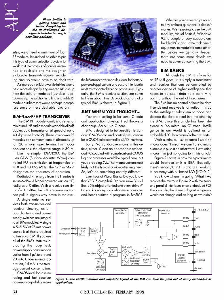
CIRCUIT CELLAR INK FEBRUARY 199854
APC
VCC 4.5–5.5 V
TXD
Audio
RXD
*CD
*RX select
*TX select
Ground
10 kΩ
10 kΩ
10 kΩ
10 kΩ
SAW-controlledOscillator
FM Modulated
Tuned BufferAmplifier
TX/RXSupply
Switches
67 kΩ
Discri-minator
SignalDetect
2nd LocalOscillator16 MHz
2nd Mixer
1st Mixer
16-MHz8 pF
1st LocalOscillator
TX / RXSwitch
418-MHz8 pF
Antenna
RF Ground
ModulationLinearizer
2 A
PreAmp
sites, wed need a minimum of fourRF modules. It is indeed possible to putthis type of communications system towork, but the physics of double anten-nae at each site and the design ofelaborate transmit/receive switch-ing circuitry would have to be dealt with.
A simple pair of kids walkie-talkies wouldbe a more elegantly engineered RF lashupthan the suite of modules I just described.Obviously, the solution is to find a suitable RFmodule out there that would perhaps incorpo-rate some of these desirable functions.
BiM-4xx-F/HP TRANSCEIVERThe BiM RF module family is a series of
miniature UHF radio modules capable of half-duplex data transmission at speed of up to40 kbps (see Photo 2). These low-power RFmodules can communicate at distances upto 120 m over open terrain. For indoorapplications, the effective range is 30 m.
Like the simpler TXM/RXM, the BiMuses SAW (Surface Acoustic Wave) con-trolled FM transmission at frequencies of418 and 433.92 MHz. The xx in 4xxdesignates the frequency of operation.
Radiated RF energy from the F series isset at 6 dBm. A higher powered version (HP)radiates at 0 dBm. With a receive sensitiv-ity of 107 dBm, the BiMs receiver sectioncan pull in signals way down in the dust.
A single antenna ser-vices both transmitter andreceiver circuitry, as on-board antenna and powersupply switches are integralto all BiM modules. A single4.55.5-V at 25-mA powersource is all thats requiredto fire up a BiM. If you useall of the BiMs features in-cluding the loop test,power-supply consumptionvaries from 1 µA to around20 mA. Under normal op-eration, 15 mA is the aver-age current consumption.
CMOS-level logic inter-facing and fast receiverpower-up capability make
the BiM transceiver modules ideal for battery-powered applications and easy to interface tomost microcontrollers and processors. Typi-cally, the BiMs receiver section can cometo life in about 1ms. A block diagram of atypical BiM is shown in Figure 1.
JUST WHEN YOU THOUGHTYou were settling in for some C code
and application physics, Fred throws achangeup. Sorry. No C here.
BiM is designed to be versatile. Its stan-dard CMOS data and control pins screamfor a CMOS microcontrollers I/O interface.
Sorry. No stand-alone micros in this ar-ticle, either. C and an appropriate embed-ded PC coupled with some front-end CMOSlogic or processor would be typical here, butyoure reading INK. That means you are mostlikely not the typical cookie-cutter engineer.So, lets do something entirely different.
Ever hear of Visual Basic? Did you knowthat VB V.5 compiles? Did you know VisualBasic 5 is object oriented and event driven?Do you know anybody who uses a computerand hasnt written a program in BASIC?
Whether you answered yes or noto any of these questions, it doesntmatter. Were going to use the BiMmodules, Visual Basic 5, Windows95, a couple of very capable em-bedded PCs, and some trick benchequipment to modulate some ether.But before we get any deeper,there are some more details weneed to cover concerning the BiM.
BiM BASICSAlthough the BiM is nifty as far
as RF stuff goes, it is simply a transmitterand receiver that can be controlled byanother device of higher intelligence thatneeds to transport data from point A topoint B without the aid of hard wires.
The BiM has no control of how the datait sends and receives is formatted. It is upto the intelligent subsystem to code anddecode the data placed into the ether bythe BiM. Since this article has been de-clared a no micro, no C zone, intelli-gence in our world is defined as anembedded-PC hardware/software suite.
Wait a minute. Just because I said nomicros doesnt mean we cant use a microexample to push a point forward. I love usingmicros. Im just not going to in this article.
Figure 2 shows us how the typical microwould interface with a BiM. Basically,theres serial I/O (SDO and SDI) workingin harmony with bit-based I/O (I/O 02).
You know where Im going. What if wereplace the micro in Figure 2 with the serialand parallel interfaces of an embedded PC?Theoretically, the physical layout in Figure 2would not change and as long as we didnt
Figure 1The CMOS interface and simplistic layout of the BiM can take the pain out of many embedded RFapplications.
Photo 2This isgetting better and
better. Everything forthe RF-challenged de-
signer is included in a singleneat little package.

CIRCUIT CELLAR INK FEBRUARY 199856
APC
violate the BiMs 5-V interface rule, thewhole thing would probably fly. Right!
How many times have I taken thatshortcut? How many times have you takenthat shortcut? How many times did you endup buffering things you knew you shouldhave buffered in the first place?
If you want to connect directly out of thestandard embedded ports, be my guest. Ifnot, Figure 3 ensures that CMOS levelswill be present at the BiMs interface.
Now that the data and control inter-faces between our embedded PC and theBiM have been defined, lets look at whatneeds to be considered once the data hasentered the BiMs electronics. First of all,the data path within the BiM is AC coupled.
As you well know, where there are capaci-tors or capacitance, timing is everything. Theminimum time allowed between consecutivetransitions is 25 µs, while 2 ms is the maxi-mum. By keeping our data rates between4800 and 38,400 bps, even the worstcase of all zeros or all ones in an eight-bitframe wont violate the timing window.
To provide increased immunity to RFinterference, the BiMs AFC and data-slicerelectronics require a preamble of at least3 ms of hex 55 or hex AA characters. Theseare transmitted before data at the RXDoutput may be considered reliable. The data-sheet recommends 5 ms of preamble forincreased data integrity. This preamble isalso specified as the receive settling time.
To reduce pulse width distortion and in-crease noise tolerance, it is recommendedthat the mark/space ratio be kept as closeto 50:50 as possible. The data slicer is opti-mized for 50:50 but can handle ratios of30:70 or vice versa with some degradation ofthe data quality. The bit error rate is basedon the mark/space ratio over a 4-ms period.
If youve assumed that we will be provid-ing the BiM serial data from a UART-basedembedded serial port, youre on the beam.With that assumption and our workingknowledge of typical async data packets,we have quickly come to the conclusionthat we cant guarantee a 50:50 mix of
transitions within any particular dataframed from the UART.
The good news is that the BiM canhandle raw RS-232 serial data as long assome rules are followed.
First of all, the data rate must fall between4800 and 38,400 bps. Our applicationcan live with this. If you need a higher speedfor your app, just hold on. Ill get to that.
Of course, the transmission must be inhalf duplex mode. No problem there, either.
Secondly, the data must be packetizedand contain no gaps between the bytes.Heres how thats done. The preamble issent for a minimum of 5 ms, which allowsthe data slicer to settle.
This is immediately followed by a coupleof bytes of hex FF. The hex FFs lock the UARTby placing the datastream in a marking state.The UART expects to see a start bit followingthe hex FF bytes. A unique start of messagebyte is then sent followed by the actual data.
If you want extreme accuracy, a checksumor CRC byte is sent at the end of the trans-mitted packet. Since this is a duplex system,the receiver can verify the CRC or checksumand request a resend of the last packet ifthings dont match.
Now, for you guys and gals who want tooperate at hyperspeed, you need to adhere tothe 50:50 mark/space ratio rule. If you planto operate above 20 kbps, this is mandatory.Three ways are recommended to get the50:50 mark/space ratio and thus transmis-sion speeds of up to 40 kbps between BiMs.
The first method is called Biphase orManchester coding. Each bit is sent as two
bits. The first bit is the actual data bit to besent and the second bit is the first bits comple-ment. This guarantees a transition in the cen-ter of the bit which is a perfect 50:50 mark/space ratio. The 100% redundancy of thedata offers 40 kbps throughput, but it actuallyequates to only 20 kbps of usable throughput.
Another scheme called byte-coding as-sumes that only a subset of the ASCII codeis required as data. A look-up table isneeded as only 70 of the possible 256eight-bit codes are used. All of the 70codes contain four ones and four zeros. Inactuality, only 68 of the 70 are usedbecause hex 0F and hex F0 are left out tominimize consecutive zeros and ones.
Using a standard UART setup for one stopbit, one start bit, and no parity, these codesmeet the 50:50 mark/space requirement.An additional plus to this method is thaterror checking is simplified because of the4:4 ratio of ones to zeros in each byte.
FEC coding is the third way to balancethe mark/space ratio. In this coding scheme,each byte is sent twice. The first send is truedata, with the second send being a comple-ment of the first.
This scheme can be enhanced by add-ing a parity bit. With parity, the decoderalgorithm can check the true byte for correctparity and on parity failure select the nextinverted byte to use for data if its not corrupt.
The bottom line is that packets sentbetween BiMs must contain a preamble, acontrol bit or bytes, data, and some formof error checking in gapless succession.
The preamble gives the receiver in theBiM time to stabilize. The preamble time maybe increased to allow more time for carrierdetection or receiver wakeup and initial-ization.
The packets control area is used for manypurposes. Primarily, it signals the beginning ofa message. Other information such as packetnumber, byte counts, or flow-control char-acters may be included here.
GNDRFGND
0 VVCC
*RX*TX
TXDAF
RXD*CD0 V
BiM-UHFRadio DataTransceiver
0 V
RF I/O50 Ω
181716151413121110
123 +5 V
Test Point
Microcontroller
I/O 0I/O 1SD 0
SD 1I/O 2
Figure 3Adding this minimal number of components provides a fully buffered CMOS interfaceto the BiM. Note the pulse stretcher attached to the CD pin.
GNDRFGND
0 VVCC
*RX*TX
TXDAF
RXD*CD0 V
BiM-UHFRadio DataTransceiver
0 V
RF I/O50 Ω
181716151413121110 100 kΩ
10 nF
+5-V Supply
Enable/*Sleep
TX/*RX
TX Data
RX Data
Carrier Detect0 V
NAND Gates = 74HC132 or 4093NOR Gates = 74HC82 or 4001
123
Test Point
Figure 2As you can see,
this is a perfectunion of RF and mi-
cro. Its also the basisfor a perfect union of RF
and embedded PC.

57FEBRUARY 1998 EMBEDDEDPC
As well, an address area can be insertedbetween the control and data areas. Theaddress data can be source or destinationaddress information or a unique site identifier.
Data is data is data is data. The onlyrestrictionkeep the actual byte count aslow as possible. In case of CRC or checksumerrors, its more bandwidth efficient to resendsmaller packets, especially if there are mul-tiple BiM stations that must communicatewith each other or a central host site.
BASIC COMMUNICATIONSUsing Visual Basic 5 and the MSComm
Control, lets assemble a software-baseddatascope that shows the raw data flowingbetween BiMs connected to a couple of
embedded-PC serial and parallel ports.The hardware I use is depicted in Figure 3.
Each embedded PC is equipped withenough memory and disk space to accommo-date Windows 95 and the Visual Basic 5development suite. I chose the Teknor VIPer806 and the Advantech PCM-4862 becausethey can support this kind of environment.
As well, the VIPer and the 4862 bothhave Ethernet adapters. I can develop theVB code on a third machine and transferit electronically via the Florida Room LAN.
Third machine? Lets park the truck hereand walk awhile. I use bunches of supporttools that I dont talk about to make whatyou see here. But, theres one tool I useevery day that you need to know about.
Private Sub MSComm1_OnComm() Select Case MSComm1.CommEvent Case comEvCD If MSComm1.CDHolding Then txtwindow.Text = txtwindow.Text & MSComm1.Input End If End SelectEnd Sub
Listing 1Visual Basic relieves the pain of getting the transmitted data. Here, we simplywait for the carrier detect to active.
Listing 2The Form_Load routine sets up the serial port. After that, its just a click of theTransmit button to send the complete data packet.
Private Sub Form_Load() 'init comm parms MSComm1.CommPort = 1 MSComm1.Settings = "9600,N,8,1" MSComm1.InputLen = 0 MSComm1.PortOpen = TrueEnd Sub
Private Sub btnxmit_Click() 'set up storage and variables Dim x As Integer Dim xmitpreamble As Variant Dim xmitmsg As Variant Dim xmitcrc As Variant Dim msg As String Dim recbuf As String xmitcrc = 575 'preload crc with 0xFF+0xFF+0x41 xmitpreamble = Chr$(85) 'define message to send msg = "Circuit Cellar" msglen = Len(msg) xmitcrc = xmitcrc + msglen For x = 1 To msglen 'calculate a checksum xmitcrc = xmitcrc + Asc(Mid$(msg, x, 1)) Next x xmitcrc = xmitcrc And &HFF xmitmsg = Chr$(255) & Chr$(255) & Chr$(65) & Chr$(msglen) _ & msg & Chr$(xmitcrc) 'send message packet For x = 1 To 700 'send preamble MSComm1.Output = xmitpreamble Next x MSComm1.Output = xmitmsg 'send message packetEnd Sub

CIRCUIT CELLAR INK FEBRUARY 199858
APC
Im con-stantly hooking
up different embed-ded platforms for this
and that. Its a drag to con-nect a monitor here, a key-
board there, and then swap themfor another embedded PC project.
You either buy a bunch ofmonitors and keyboards and laystuff all around, or do what I did.Get yourself a Vetra MegaSwitch.
I use the eight-port model (VIP1328) in the Circuit Cellar FloridaRoom. Each port is equipped with acable for video, keyboard, and mouse. Byjust pressing a button on MegaSwitchs frontpanel, a single monitor, keyboard, and mouseswitches between eight embedded and/or desktop PCs. OK, back in the truck.
MSCommThe MSComm control is VB5s way of
controlling serial communications via avail-able serial interfaces. With MSComm, youcan open or close a serial port, set up theserial port parameters, and transfer datavia the serial ports I/O structure.
I mentioned that VB5 was object ori-ented and event driven. Well, thats al-most completely true. VB5 doesnt let cer-tain object-oriented things happen thatwould let you corrupt original VB5 objects,but for our purposes thats OK.
By employing a property called Comm-Event, we can interact with our BiM databy reacting to a change in events. In thecase of our datascope, we will key on achange in state of the CD pin. Listing 1describes how we will put MSComm towork.
PULLING DATA OUTOF THIN AIR
Its obvious that BiM canradiate bit patterns into electro-magnetic space. So, it doesntmean much to just send somedata and say, Theresee.
Thats why I built a pseudo-datascope so we can see whatgoes out and what comes in.From its beginning, Visual Basichas been strong in the userinterface department. Photo3 is a view of our datascope.
Heres the plan. Since BiMsare half-duplex devices, one PC will transmit,and the other will receive. The receiver runscode using MSComms CommEvent propertyto trigger reception on a change in CarrierDetect from the BiM. If the change is a truedetection of carrier, then the receiver willreceive the RF-based datastream and dis-play it on our datascope screen.
This is what we should see. First of all,the transmitting embedded PC is pro-grammed to send a 700-ms preambleconsisting of hex 55. This is approximately700 8-bit characters at 9600 bps.
Photo 3Its all here, the preamble and everything else. The A beginsour message, which is surrounded by a message length and checksumcharacter.
59 FEBRUARY 1998 EMBEDDEDPC
APC
IRS416 Very Useful
417 Moderately Useful418 Not Useful
Fred Eady has over 20 years experienceas a systems engineer. He has workedwith computers and communication sys-tems large and small, simple and com-plex. His forte is embedded-systems de-sign and communications. Fred may bereached at [email protected].
SOURCESRXM-418 UHF receiver,TXM-418 transmitter, LC seriesLinx Technologies, Inc.575 S.E. Ashley Pl.Grants Pass, OR 97526(541) 471-6256Fax: (541) 471-6251www.linxtechnologies.com
Abacom Technologies67 Hamptonbrook Dr.Etobicoke, ONCanada M9P 1A2(416) 242-3120Fax: (416) [email protected]
VIPer 806Teknor Industrial Computers, Inc.616 Cure BoivinBoisbriand, QCCanada J7G 2A7(514) 437-5682Fax: (514) 437-8053www.teknor.com
PCM-4862American Advantech Corp.750 E. Arques Ave.Sunnyvale, CA 94086(408) 245-6678Fax: (408) 245-8268www.advantech-usa.com
Once the receiving BiM locks in, twobytes of hex FF will be sent. This shouldlook like a marking line to the UART.
The next character out will be a hex 41or ASCII A. This is our control characterand signals the VB5 application that realdata is to follow. Listing 2 is the codesnippet that created the view in Photo 3.
ROGER THATOVERWhat weve just done is transmit and
receive real data over the distance of afew feet. With low-power RF applications,thats sometimes all that is needed.
In Part 1, I discussed the good and bad oftransmitting data over certain distances. Inreality, where you are and over what dis-tances you must communicate determine thepower levels and frequencies you may use.
After speaking to the folks at Abacomand Linx, I found that other countries havefar different attitudes about RF communica-tions than we do here in the States.
To that, I say this: Dont use the FCCregulations for applications geared for othercountries, and dont think FCC regulations arerestrictive. The low-power RF modules I de-scribed are perfect for most applications.
For instance, inventory and POS appli-cations dont need to pass data over agreat distance. Your keyless entry systemfor your car is another good example. Youdont unlock or lock it from a mile away.Youre right there up close.
If you do find an application where ahigher powered RF field is required, thereis equipment available and FCC regula-tions that permit its use.
The BiM module is the basic buildingblock for a multitude of RF-based applica-tions. With careful selection of frequency,power output, and antenna characteris-tics, it can provide a solution to many ofyour RF data-transfer problems.
By establishing itself as an embeddedbuilding block, the BiM proves that itdoesnt have to be complicated to beembedded. APC.EPC

60 Issue 91 February 1998 Circuit Cellar INK®
Codesign FEATUREARTICLE
Richard Moseley
aFar too often, designschedules go awrydue to the difficultyof coordinatinghardware and soft-ware design teams.Richard brings us upto date on codesigntools and how theypromise a smoother,faster developmentcycle in the future.
s pressures in-crease to bring
products to marketmore quickly, design
engineers are looking for ways tospeed up design cycles and decreasethe time required for debugging proto-types and fixing problems.
Of course, to accomplish theirgoals, they must find ways to do thiswithout suffering the penalties associ-ated with learning curves that resultfrom using new design tools.
One promising solution is codesign—a synchronized collaboration betweensoftware- and hardware-developmentteams.
The most common approach forembedded-system design positionshardware and software teams on un-connected paths that are only reunitedafter the creation of the hardware proto-type.
These individual design groups makepresumptions about each other’s contri-bution to the overall system, whichare magnified and later surface assignificant errors that can take a big tollon budgets and schedules.
In addition, time-to-market urgencytypically mandates that fixes be carriedout via software workarounds rather
than hardware redesign. This approachcan result in significant compromisesto the performance of the finishedsystem.
In a perfect world, hardware andsoftware teams would work in harmonyfrom initial design concept all the waythrough to benchmarking the finishedsystem, staying in constant communi-cation as the design reaches criticalintegration and test phases. The twogroups would work together, and theinterface between their designs wouldbe constantly validated to identifyproblems early in the design cycle.
Employing the precepts of codesign,simulation and verification would beperformed on hardware and softwaresynergistically, resulting in robustdesigns with added functionality andshaving time off development cycles.
This next-generation system-leveldesign formula embodies the creationof a virtual prototype—a speed-opti-mized combination of software simu-lation and hardware emulation thatprecisely mimics the target system,albeit at a slower speed in most cases.
This environment would feature anew generation of interoperable co-design tools for simulation and verifi-cation that identify and resolve errorsduring the specification and partition-ing phases. The result: clearly definedparameters for hardware and softwareimplementation.
Even though most concede that theisolation of hardware and softwareimplementation paths is less thanoptimal, it’s still the most commonmethodology used in designing em-bedded systems. Part of the problemlies in the fact that until recently,design-tool technologies haven’t beenavailable to orchestrate cooperativedesign efforts between hardware andsoftware development.
However, the design-tool communityhas made great strides with this prob-lem, and a number of significant newtool technologies have emerged overthe past year.
But, sometimes even the best-laidplans suffer in implementation, andmost codesign solutions are far fromperfect. In truth, none of the codesignsolutions available today are an optimalfit for every application since they are
The Evolving RelationshipBetween Hardware and Software

Circuit Cellar INK® Issue 91 February 1998 61
often largely based on theparticular vendor’s core com-petency, whether it be soft-ware or hardware emulation.
Each approach is moresuited for a specific set ofrequirements. Even those show-ing the most promise are likelyto endure slow adoption sincethey’re regarded with skepti-cism until proven.
Significant barriers also liein the organizations targetedby codesign-tool vendors. Evenif robust codesign tools andenvironments were available,the infrastructure in place atmost system OEMs couldseriously hamper the tools’ acceptance.
Problems such as a lack of commu-nication between design teams, differ-ent management systems for hardwareand software, and deep-seated biasesin engineering managers contribute toan unfavorable climate for the imple-mentation of codesign methodologies.
Although the potential benefits ofimplementing a codesign methodologyoutweigh the obstacles to its adoption,this is only true if the codesign isplanned well in advance of the designproject. For instance, the value ofcoverification is extremely high earlyin the design process.
With today’s time-to-market de-mands, attaining design closure as soonin the process as possible is critical. Ifthe coverification process can be carriedout with a high degree of certainty, anylater problems associated with integra-tion and testing will be minimized.
A NEW PLAYING FIELDSoon, however, the overall situation
may change dramatically. Players inthe codesign-tool arena seem to bemigrating toward a common approach—a speed-optimized mix of softwaremodeling and hardware emulation. Ayear from now, these tools are likelyto be robust and remarkably similar inthe features they offer.
Widespread adoption of codesignmethodologies and tools isn’t a questionof “if” but “when.” In fact, it would bebeneficial for companies to work withcodesign-tool vendors even this early.By doing this, they’d help shape tool
features, while gaining the experiencerequired to increase the probability ofa successful design project.
With today’s high-performance sili-con technologies inexpensively combin-ing tremendous computer horsepowerwith integrated peripherals and memory,it’s no surprise the software contentof today’s embedded systems hasexploded. Most estimates place thesoftware-development cost for a typi-cal system at well over half the totaldevelopment budget—a reality thatthe system development-tool industryhas practically ignored for years.
In addition to the hardware compo-nents, such as one or more CPUs,possibly a coprocessor (e.g., a DSP orgraphics coprocessor), an ASIC or two,some memory, and assorted off-the-shelfparts, a typical embedded systemincludes software components like anRTOS, device drivers, and an embeddedapplication.
CODESIGN IN DEVELOPMENTMost aspects of the hardware and
software development process can beautomated, except in the cases of systemdefinition, architectural design, andsoftware/hardware partitioning. Aswell as not being well automated, theseexceptions are fairly disconnectedfrom the implementation process,which is itself divided into distincthardware- and software-design efforts.
As a result, hardware and softwareengineers don’t get to test their respec-tive subsystems together until a physi-cal prototype exists. Unfortunately,
most problems in the hard-ware/software interface aren’tdiscovered until this point,possibly forcing a redesign.And so, schedules slip. Often,the integration and testingphase may represent the criti-cal path or as much as 50% ofthe development cycle.
To counteract these prob-lems, codesign solutions areextremely attractive. Unfor-tunately, the pieces aren’t allin place yet. For instance,general-purpose automatedtools for system definition,architectural design, and soft-ware/hardware partitioning
that offer enormous leveraging overthe subsequent phases of developmentare rare today.
In fact, most mainstream develop-ment-tool vendors focus on the imple-mentation portion of the process (i.e.,linking the software and hardwaredesign phases of the project after par-titioning). However, a lot can be gainedby shortening the implementation/test phase.
Current codesign methodologiesfocus on two basic approaches to creat-ing a virtual prototype. They attemptto shorten the “software waiting forhardware” gap encountered in mostdevelopment efforts.
One camp, with roots deeply embed-ded in hardware and in-circuit emula-tion technologies, provides for thecreation of the virtual prototype usinga “black box” filled with FPGAs.
The other camp, whose technologyoriginated from the high-level simula-tion and abstraction approaches of EDA,has developed unique techniques forspeeding up logic simulation in orderto build a virtual prototype.
Each approach has advantages anddisadvantages, but one thing is clear.Both camps are on intersecting courses.Product developments will start to lookquite similar as these new productscontinue to mature in the marketplace.
HARDWARE EMULATIONThe integration levels and perfor-
mance provided by today’s FPGA ven-dors, plus the maturity of tools availablefor mapping the register-transistor-
DebugInterface
Emulator/Debugger
SystemSenseInputs
AHDL
SystemHardware
Drivers
Verilog HDL
CommunicationInterface
Hardware Emulator
SRAM
Vendor-SpecificSoftware Model
DRAM
C Model
EPROM(RTOS)
Second Vendor’sEmulator/Debugger
ICACHE
ColdFireCore
ParallelPort
InterruptController
DRAMController
MBUS DUART
DualTimer
ChipSelects
SRAM
Figure 1— Chip manufacturers are doing an excellent job of emulating thelogic that goes onto a chip, as evidenced by shrinking debugger ports on new,complex chips. Next tasks: emulating the chip in both systems and stand-alone environments as well as eliminating bugs.

62 Issue 91 February 1998 Circuit Cellar INK®
development of a number of criticalmodels—an ISS model for the targetprocessor and any off-the-shelf VLSIcomponents, a bus-functional model,and a memory model.
If models are not readily availablefrom the chip vendor in a form thatworks with Seamless CVE, the timerequired to create them can add monthsto the overall development cycle. Plus,most vendors won’t provide them
even if they are available unlessa binding nondisclosure agree-ment is signed and you’re signedup to buy chips. Some vendorsrefuse to supply these modelsor even develop them to pro-tect their intellectual property.
You can also include actualcomponents in your virtualprototype if they’re available,or you can do hardware emula-tion of blocks using Mentor’sSimExpress box. Mentor’sstrategy is to enable designersto create the level of abstrac-tion required.
Both approaches require hard-ware to be well-modeled and -definedbefore the creation of the virtual pro-totype, much more so than the soft-ware. The software then turns up bugsthat require a redesign on portions ofthe hardware.
TOOLSETSBefore taking on a codesign meth-
odology, examine the tools closely toensure that specific project requirementscan be met in the allotted time. Co-design tools should be adopted forsmaller projects to give you time tolearn the tools before committing themethodology to a critical design project.
A number of things should be con-sidered before committing to codesign.Are the proper models available forthe functions required? If not, howwill the models be obtained?
What is the cost (in dollars and time)if models must be developed? If mod-els must be developed, will the infor-mation be available to develop them?
What developments, if any, areplanned by the chip or tool vendor thatcould aid the design process? Whatother tools will work with the targetcodesign toolset?
level description of hardware, enablehardware emulation of a target systemto be realized fairly quickly and easily.
The advantage of the hardware-emulation approach, led by systemssuch as Quickturn Design Systems’System Realizer, is that they providegate-for-gate, wire-for-wire prototypingof the target system. In some cases, theymay even be able to operate at thetarget system’s full operating speed.
Motorola used System Real-izer during the verification phaseof the MC68060 and ColdFiremicroprocessor cores (see Figure1). During the ’060 verification,prior to first silicon, over onetrillion instructions were run toverify that the chip was runninginstructions correctly, as illus-trated in Figure 2.
The main downside to thehardware-emulation-only ap-proach is the investment infront-end work required to mapthe system into programmablelogic, although tools designedsolely for this task greatly fa-cilitate the process. Once the systemis mapped, hardware changes can bequickly and easily implemented.
This step, however, must be com-pleted at some stage of the designprocess anyway, to analyze the validityof the customer-designed logic. Theonly disadvantage is that the gate-levelimplementation must be completed atan earlier stage in the project.
SEAMLESS SIMULATIONOn the simulation front, Mentor
Graphics recently released its SeamlessCo-Verification Environment (CVE).Using a unique approach to speedingup the verification process, this sys-tem enables the designer to minimizethe time spent in logic simulation byisolating the CPU and memory fromthe rest of the system logic.
The CPU is modeled using an in-struction-set simulator (ISS), whichcan run compiled C or assembly codeat millions of instructions per secondin full-emulation mode. The ISS tracksthe number of CPU cycles requiredfor each operation for performanceanalysis and synchronizing with therest of the system. By abstracting the
memory in addition to the CPU, amajority of the bus cycles, which aresimply data or instruction fetches, canbe avoided.
To handle concerns about accuracyor analysis at a deeper level, a bus func-tional model is also created in C toenable the logic simulator to stimulatebus activity and interact with the restof the system logic. The memorysystem is also modeled in the logic
simulator so it’s visible to the rest ofthe logic. The memory and bus func-tional models communicate with theISS using an API.
However, this approach alone isnot enough, since waiting for the logicsimulator to complete each operationrenders it unusable. In addition, thecontents of the memory model in thesimulator must synchronize with theimage expected by the CPU withouttying up resource-intensive bus cycles.
To solve this problem, SeamlessCVE employs an intelligent kernelbetween the ISS and logic simulator.It keeps the two simulations synchro-nized and maintains a consistent viewof memory for the CPU and logic.
Most importantly, it optimizes theperformance of the overall system simu-lation by letting the user selectivelyfilter certain classes of bus activity toavoid unnecessary stimulation of thelogic simulator. For example, once theinstruction fetch cycle has been char-acterized for a portion of the memorymap, fetches can be turned off to reduceload on the logic simulator.
The main disadvantage to the simu-lation approach is that it requires the
Figure 2— The 68060 verification experience demonstrated that the verifi-cation process weeds out many bugs that would have slipped by throughthe sheer number of instructions run against the part. However, a certainnumber of bugs only manifest themselves in a full-blown end system thatincludes memory components, peripherals, and perhaps other processors.
Bug
Cou
nt21 Months
40 Billion Instructions3 Months
1 Trillion Instructions
ModuleVerification
Chip-LevelIntegration
and Verification
Target SystemIntegration
and Verification
Simulation and Verification Time

64 Issue 91 February 1998 Circuit Cellar INK®
Codesign toolsets should embody astart-to-finish solution that ideallyincludes:
• a “real” fully-integrated hardware/software design environment
• software and hardware emulationwith programmable breakpoints
• mixed hardware emulation andsimulation with visibility at anylevel
• tool-vendor interface interoperabil-ity (a common interface standard)
• high abstraction levels to speed thesimulation of large systems
• a flexible, distributed system thatallows for multiple design seats
• minimized cost per design seat• an investment outlay that’s easy to
amortize over large production runs• a portable stand-alone detachable
emulation board for system demos• the ability to keep intellectual prop-
erty secure for model or chip vendors
WHAT’S AHEAD?As a methodology, codesign requires
a fair bit of maturing before it can
I R S419 Very Useful420 Moderately Useful421 Not Useful
Richard Moseley, principal staff engi-neer with Motorola, currently workswith integrated systems, directing asystems and design support teaminvolved in ColdFire and 680x0 systemsusing the FlexCore standard cell-design methodology. Richard has beeninvolved in semicustom library devel-opment, CAD, and design since 1982.You may reach him at [email protected].
SOURCESSeamless CVE, SimExpressMentor Graphics, Inc.8005 SW Boeckman Rd.Wilsonville, OR 97070(503) 685-7000Fax: (503) 685-1205www.mentorg.com
MC68060, ColdFireMotorolaMCU Information LineP.O. Box 13026Austin, TX 78711-3026(512) 328-2268Fax: (512) 891-4465
System RealizerQuickturn Design Systems, Inc.440 Clyde Ave.Mountain View, CA 94043(415) 967-3300Fax: (415) 967-3199www.quickturn.com
enjoy the kind of widespread adoptionhoped for by the companies developingcodesign products.
In the coming year, many new andupgraded products are anxiously beingexpected from development-tool ven-dors that could push the methodologyinto acceptance at mainstream systemOEMs.
But, it’s certainly true that codesignhas some other hurdles to overcome.Many of these rise primarily from themind-set of engineers involved inhardware and software design.
For now, sit back and observe. Onlytime will tell what will develop. I

66 Issue 91 February 1998 Circuit Cellar INK®
Choosing the RightCrystal for Your Oscillator
FEATUREARTICLE
Norman Bujanos
sAlthough critical tothe timing of yourdesign, crystals areglossed over inengineering schools.Norman puts a stopto that. His review ofcrystal parametersgets you up to snuffwhen it comes topicking the rightcrystal for your design.
electing quartzcrystals for oscilla-
tors can be confusingand mysterious. Engineer-
ing programs tend to give them only acursory overview.
Hence, many engineers are unfamil-iar with crystal parameters and jargon.A crystal datasheet can appear to beas cryptic as Egyptian hieroglyphics.
In this article, I cover crystal param-eters and explain how system design canaffect clock accuracy. It should makecrystal selection significantly easier.
WHY QUARTZ CRYSTALSThe quartz crystal integrates me-
chanical and electrical characteristics.If quartz is stressed, an electric field isgenerated in the direction perpendicularto the applied stress.
Conversely, if an electric field isapplied to a quartz crystal, a mechani-cal stress appears in the direction per-pendicular to the applied stress. Thiseffect, known as the piezoelectric effect,is the basis for quartz being used soextensively in crystal manufacturing.
By placing a quartz crystal betweentwo electrodes and applying a changingvoltage, the crystal can be made tovibrate. Maximum vibration amplitudeoccurs when the frequency of the chang-ing voltage matches the crystal resonant
frequency. Oscillator circuits using aquartz crystal vibrate at the crystalresonant frequency.
High Q is one of the most desirablefeatures of quartz crystals. It is a mea-sure of how much energy is lost dueto vibration. In mechanical terms, Q is:
Q = 2π Energy stored per cycleEnergy lost per cycle
In electrical terms, Q is the inductivereactance at resonant frequency dividedby the equivalent series resistance (ESR).
A crystal with a high Q loses littleenergy while vibrating. Commercial-grade crystals have Qs ranging between20,000 and 200,000. High-precisioncrystals have Qs up to 3 million.
In addition to high Qs, quartz crys-tals tend to be incredibly stable. Theonly drift associated with crystals isfrom temperature fluctuations andaging. Temperature effects are about100 ppm over the operating range, whileaging effects are around ±5 ppm per year.
TIMING BUDGET AND ACCURACYWhen selecting a crystal, carefully
consider how accurate your systemhas to be. Crystal selection and oscil-lator design must be weighed equally.
These factors work together, influ-encing the system operating frequencyand cost. Typically, the more accuratea system is, the more expensive it isto build.
If you’re building a system with anRTC, your target accuracy should be ±2min. per month. PLL reference clocks,however, can tolerate less accuracy.
Four crystal parameters play a keyrole in system accuracy. The contri-bution from each must be added toobtain the total system accuracy.
Each parameter can be adjustedwithout influencing the others. Thisparameter independence makes custom-izing crystals attractive.
However, customization results inincreased system cost. Look carefully atyour system requirements. Try to usereadily available, off-he-shelf crystals.
FREQUENCY TOLERANCEThe frequency tolerance (i.e., cali-
bration effect) is the first of the fouraccuracy-budget parameters. It is a

Circuit Cellar INK® Issue 91 February 1998 67
∆+ppm
∆–ppm
AT-Cut Curve
Increasing TempDecreasing Temp
25˚CBT-Cut Curve
room-temperature (i.e.,25°C) spec stating howclose the actual crystalfrequency is to its speci-fied frequency. Likemost crystal specs, itis in parts per million.
For example, a32,768-Hz crystal mayhave a frequency toler-ance of ±20 ppm. At25°C, the resonantfrequency can be any-where between32,768.65536 and32,767.34464 Hz.
The 32768 crystal isknown as a watch crys-tal. This system mightsound highly accurate,but when you considerits accuracy impactover a month, this oneparameter alone cancause the watch to be off by almost1 min.
Equation 1 shows that a ±20-ppmfrequency tolerance can account forabout 52 s per month:
60 smin × 60min
h× 24 h
day× 30
daysmon
× ± 201,000,000 = ±51.84 s
mon (1)
FREQUENCY STABILITYFrequency stability is the second
item to add to the timing budget. It isa function of temperature and is relatedto the crystal cut type.
The most common crystal cut typesare AT and BT. Their temperaturestability curves are different—a factthat should be considered when you’redesigning a system.
The AT curve is cubic [1], as depictedin Figure 1. Note that the curve movesbetween the +ppm and –ppm areaswith temperature.
If a system using an AT-cut crystalis exposed to temperature fluctuations,the temperature effects tend to averageto zero over time. However, an error isintroduced from not operating at 25°C(i.e., crystal calibration temperature).
The BT cut, common in low-fre-quency crystals, is a parabolic form.Increasing or decreasing temperatures
both cause a decreasing resonant fre-quency. Unlike the AT-cut crystal,temperature fluctuation effects do notaverage to zero.
AGINGThe third item in the timing budget
is aging as it relates to crystal contami-nation and drive level. Resonant fre-quency changes as a function of time.
It tends to be related to crystal con-tamination. That is, particles eitherdrop off or fall onto the quartz surface.Because this happens inside the crystalcase, there isn’t anything you can doabout it. It’s up to the manufacturer.
However, keeping the drive level lowcan reduce aging effects as the crystal isnot knocked around as much. Choosecrystals that are hermetically sealedfor best aging characteristics.
LOAD CAPACITANCEThe fourth timing budget parameter
to consider has to do with load capaci-tance. For parallel resonant circuits,there is a load-capacitance spec.
If the load capacitance of your circuitdoesn’t match the crystal load capaci-tance, there is a resonant frequencyshift. I’ll discuss this effect shortly.
One nice characteristic of quartzcrystals is that all of these parametersare independent. Each one can be
adjusted without affect-ing other parameters.
You can request acrystal with 5-ppmfrequency tolerance,and keep the otherparameters the same orchange them. However,you pay a premium forcustom-made crystals.
SERIES ANDPARALLELRESONANCE
The question ofparallel and seriesresonant crystals oftencomes up and is occa-sionally a source ofconfusion. Let meclarify the situation.
There is no suchthing as a series orparallel resonant crys-
tal. Instead, crystals have different paral-lel and series resonant frequencies.
When a crystal is calibrated at thefactory, it is trimmed to hit a particularfrequency while operating in the seriesor parallel resonant mode. The parallelresonant frequency is greater than theseries resonant frequency.
Most oscillators operate in the paral-lel resonant mode (i.e., they see a paral-lel load capacitance). Some examplesof parallel resonant oscillators are thePierce-, Colpitts-, and Clapp-styleoscillators. Series-resonant oscillators,on the other hand, are uncommon.
Transforming mechanical param-eters into electrical parameters isknown as creating the electrical dual.The equivalent electrical circuit for acrystal is shown in Figure 2. Compo-nents C1, L1, and R1 make up the crys-tal’s motional arm.
Co is the shunt capacitance. It iscomposed of packaging and lead effects,and is on the order of a few picofarads.Co is also known as the crystal’s staticcapacitance.
L1 is the crystal’s motional induc-tance. This value is determined by thecrystal’s motional mass during oscilla-tion, and is on the order of thousandsof henries.
C1 is the crystal’s motional capaci-tance. It is determined by the crystal’s
Figure 1 —AT-cut crystals (solid curve) exhibit a cubic temperature stability curve. On the other hand,BT-cut crystals (dashed curve) exhibit a parabolic temperature stability curve.

68 Issue 91 February 1998 Circuit Cellar INK®
number appears in the datasheet asthe load capacitance.
If your load capacitance doesn’texactly match the load capacitance inthe datasheet, your oscillator won’t runat the spec Fp frequency. (I look at theeffects of mismatched load capacitancein the next section.) Note that theparallel resonant frequency is greaterthan the series resonant frequency.
FREQUENCY TOLERANCE ANDLOAD CAPACITANCE
When the oscillator circuit loadcapacitance doesn’t equal the crystalspec load capacitance, the oscillator’soperating frequency is different fromthe crystal’s frequency tolerance spec.
Equation 3, for Fp, shows that asthe board attributed load capacitanceincreases, Fp decreases. The change infrequency as a result of mismatchedload capacitance is:
stiffness, and is on the order of a fewfemtofarads.
R1 is the crystal’s ESR when oscil-lating, and it is related to mechanicalloss during oscillation. ESRs rangefrom a few ohms to tens of thousandsof ohms.
If the ESR is small, the crystal loseslittle energy while vibrating. A smallESR helps with startup and continuedoscillation.
The series equivalent circuit for acrystal omits the shunt capacitor, Co.The crystal series resonant frequency is:
Fs = 1
2π LC (2)
When crystals are connected toPC boards, they see a circuit thatlooks like Figure 3. Here, CL isequal to the series combination ofCL1 and CL2, and is attributed toboard parasitics and/or load caps
added to the oscillator. The resonantfrequency changes from equation 2 to:
Fp = Fs 1 + C1
Co + CL (3)
In most cases, Fp, the parallel loadresonant frequency, is specified in thecrystal datasheets. C1 and Co are partof the crystal, but the load capaci-tance, CL, is not.
At the factory, the crystal is cali-brated (frequency-tolerance spec) witha particular load capacitance. This
Figure 2 —The mechanical properties of mass, friction, andstiffness are mapped to inductance, resistance, and capaci-tance, respectively.
Crystal SpecsHere is a list of the crystal specs, along with an
abbreviated description and typical values.
Nominal Frequency—This is the ideal crystal frequency,or target frequency at 25°C. Typical values are ±20 ppm.
Frequency Tolerance—This error is associated with thecrystal calibration at 25°C. Tolerances range from ±5to ±200 ppm.
Frequency Stability—This error is associated withtemperatures away from the calibration temperature.Most crystals are calibrated at 25°C. Moving away fromthis temperature causes a shift in resonant frequency.The temperature-dependence curve depends on thecrystal cut type. The AT cut provides the best temperature curve.Typical AT numbers may be ±100 ppm across theoperating temperature range, although you can getdown to ±10 ppm. BTs follow parabolic temperature curves. Resonantfrequency decreases with temperature changes from25°C. Typical spreads are –100 ppm across the operat-ing temperature range.
Long Term Stability—Aging characteristics are largelya function of contamination. Keep the drive level lowto reduce aging effects. Typical aging is around ±5 ppmper year.
Load Capacitance—If the load capacitance of your sys-tem (oscillator plus board) does not exactly match thecrystal load capacitance, there is a resonant frequencyshift, which you can calculate via equation 4. Typicalload capacitance values are around 20 pF.
Operating Mode—Try to stay with the fundamental-modecrystals. If you have a high-frequency oscillator (i.e.,greater than 50 MHz), use overtone crystals. Be aware ofthe pitfalls mentioned in the Mode of Operation section.
Drive Level—The crystal drive level is how much powerthe crystal can safely dissipate. Typical numbers are inthe microwatt to milliwatt range. The exact drive-levelequation is rather involved. However, a close approxima-tion can be made from the following assumptions. Referring to Figure 4, at resonance, the impedance ofthe motional arm composed of L1, C1, and R1 is equal tothe impedance of CL and Co. Power dissipation is given by:
P = I2R1
Since the current through the crystal is generally un-known, it is more useful to write the power as:
P = VZ
2× R1
where |Z| is the impedance magnitude of CL and Co, and V isthe peak voltage across the crystal. The drive level is:
P = 2π × freq × V Co + CL2
× R1
where freq is the resonant frequency [2]. For a parallelresonant circuit, the impedance goes to infinity. Thisimplies that the net current goes to zero, but in reality,energy is lost through friction and joule heating. Also, thecurrents through the motional and capacitive arms aresinusoidal and 180° out of phase.
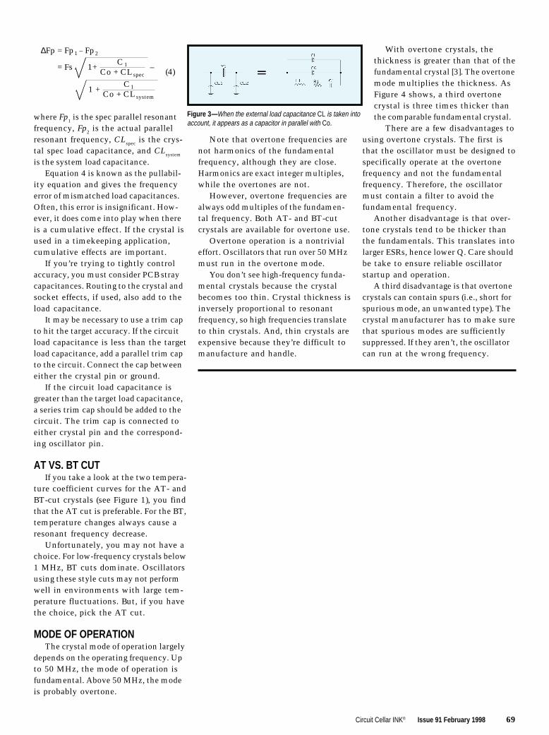
Circuit Cellar INK® Issue 91 February 1998 69
Note that overtone frequencies arenot harmonics of the fundamentalfrequency, although they are close.Harmonics are exact integer multiples,while the overtones are not.
However, overtone frequencies arealways odd multiples of the fundamen-tal frequency. Both AT- and BT-cutcrystals are available for overtone use.
Overtone operation is a nontrivialeffort. Oscillators that run over 50 MHzmust run in the overtone mode.
You don’t see high-frequency funda-mental crystals because the crystalbecomes too thin. Crystal thickness isinversely proportional to resonantfrequency, so high frequencies translateto thin crystals. And, thin crystals areexpensive because they’re difficult tomanufacture and handle.
∆Fp = Fp1 – Fp2
= Fs 1+C1
Co + CL spec–
= 1 +C1
Co + CL system
(4)
where Fp1 is the spec parallel resonantfrequency, Fp2 is the actual parallelresonant frequency, CLspec is the crys-tal spec load capacitance, and CLsystem
is the system load capacitance.Equation 4 is known as the pullabil-
ity equation and gives the frequencyerror of mismatched load capacitances.Often, this error is insignificant. How-ever, it does come into play when thereis a cumulative effect. If the crystal isused in a timekeeping application,cumulative effects are important.
If you’re trying to tightly controlaccuracy, you must consider PCB straycapacitances. Routing to the crystal andsocket effects, if used, also add to theload capacitance.
It may be necessary to use a trim capto hit the target accuracy. If the circuitload capacitance is less than the targetload capacitance, add a parallel trim capto the circuit. Connect the cap betweeneither the crystal pin or ground.
If the circuit load capacitance isgreater than the target load capacitance,a series trim cap should be added to thecircuit. The trim cap is connected toeither crystal pin and the correspond-ing oscillator pin.
AT VS. BT CUTIf you take a look at the two tempera-
ture coefficient curves for the AT- andBT-cut crystals (see Figure 1), you findthat the AT cut is preferable. For the BT,temperature changes always cause aresonant frequency decrease.
Unfortunately, you may not have achoice. For low-frequency crystals below1 MHz, BT cuts dominate. Oscillatorsusing these style cuts may not performwell in environments with large tem-perature fluctuations. But, if you havethe choice, pick the AT cut.
MODE OF OPERATIONThe crystal mode of operation largely
depends on the operating frequency. Upto 50 MHz, the mode of operation isfundamental. Above 50 MHz, the modeis probably overtone.
Figure 3 —When the external load capacitance CL is taken intoaccount, it appears as a capacitor in parallel with Co.
With overtone crystals, thethickness is greater than that of thefundamental crystal [3]. The overtonemode multiplies the thickness. AsFigure 4 shows, a third overtonecrystal is three times thicker thanthe comparable fundamental crystal.
There are a few disadvantages tousing overtone crystals. The first isthat the oscillator must be designed tospecifically operate at the overtonefrequency and not the fundamentalfrequency. Therefore, the oscillatormust contain a filter to avoid thefundamental frequency.
Another disadvantage is that over-tone crystals tend to be thicker thanthe fundamentals. This translates intolarger ESRs, hence lower Q. Care shouldbe take to ensure reliable oscillatorstartup and operation.
A third disadvantage is that overtonecrystals can contain spurs (i.e., short forspurious mode, an unwanted type). Thecrystal manufacturer has to make surethat spurious modes are sufficientlysuppressed. If they aren’t, the oscillatorcan run at the wrong frequency.

70 Issue 91 February 1998 Circuit Cellar INK®
I R S422 Very Useful423 Moderately Useful424 Not Useful
Norman Bujanos is a member of thetechnical staff at Advanced MicroDevices in Austin, Texas. He is ananalog circuit designer for the LogicProducts Division. He received a B.S.in Physics from the University ofHouston and an M.A. in Physics fromthe University of Texas at Austin.You may reach him at [email protected].
PACKAGE CONSIDERATIONSCrystals are available in a variety
of packages. There are many metal-can configurations, plastic packages,and surface-mount plastic.
Unlike ICs, the plastic version isprobably the most expensive. This isbecause the plastic version is the metalversion encapsulated in plastic. In otherwords, you pay for two packages.
Handling considerations should bethe only reason to select one packagetype over another. Performance is thesame.
CRYSTAL PLACEMENTThe old real-estate adage “Location,
location, and location” applies to crystalplacement. Closer to the oscillator isbetter.
You want to minimize parasiticsintroduced by long PCB traces. Theboard traces add to the CL value in thecrystal model. Remember, a CL thatdoes not match the CL in the specscauses a frequency shift (see equation 4).
Also, look around the crystal area tosee if there are any other clock signalsor otherwise frequently changing signalsnearby. These signals can introducenoise into the oscillator. A good (quiet)ground plane under the oscillator canhelp eliminate noise problems, too.
Consider the distance between thetwo crystal lead traces as well. Thisdistance adds to the Co term in thecrystal model. Keep the traces apartby at least the same distance as thecrystal width.
CRYSTAL CLEAR?Hopefully, terms like BT cuts, third-
overtone mode, and parallel resonance
Fundamental-Mode Crystal
Third-Overtone-Mode Crystal
Thickness = 1 Unit
Thickness = 3 Units
Figure 4 —The thickness of the third-overtone crystalslab is three times that of the fundamental-mode crystalslab.
no longer send chills down your back.This brief overview of all the crystalspecs should give you a bit more con-fidence when it comes to dealing withthem.
As I mentioned, for accuracy, youneed to consider four important specs.I discuss them in more detail in the“Crystal Specs” sidebar.
The sum of the errors contributedfrom each spec is the total systemtiming error. Since system cost isprobably an issue, do not overspecifythe crystal. Try to determine how muchtiming error your system can tolerate.Then, select the appropriate crystalusing the information given here [3,4].
The other crystal parameters dealmostly with how the crystal is beingused. For high-frequency applications,you’ll almost certainly need an over-tone crystal. For very low-frequencyapplications, it will be fundamentalbut a BT cut.
Basically, you want to design thebest system you can at a particularprice. Invest the time in planning fora good system. I
REFERENCES
[1] M.E. Frerking, Crystal OscillatorDesign and Temperature Compen-sation, Van Nostrand ReinholdCo., New York, NY, 1978.
[2] T. Williamson, Oscillators forMicrocontrollers, MicrocontrollerTechnical Marketing App. noteAP-155, Intel, June, 1983.
[3] Ecliptek Corp., www.ecliptek.com.[4] Cardinal Components, www.
cardinalxtal.com.

72 Issue 91 February 1998 Circuit Cellar INK®
Surge Suppression
MICROSERIES
Joe DiBartolomeo
l
EMI GoneTechnical
Caught inan EMIeddy? Joe’s
here to help you out.He begins by review-ing how to prepare forEMI threats, such aslightning, electromag-netic discharge, fasttransients/bursts, andinductive loadswitching.
Par
t
of41
72
78
82
MicroSeries
From the Bench
Silicon Update
DEPARTMENTS
4
ast year, I wrotea MicroSeries on
the most commonelectromagnetic com-
patibility (EMC) standardsand tests mandated for digital equip-ment by the FCC and European Com-munity (INK 79–82). As I pointed out,these EMC tests and standards havebecome de facto design specifications.
This MicroSeries builds on lastyear’s. I begin by looking at commontypes of electromagnetic interference(EMI) transients.
I then present components used toboth protect equipment from transientEMI and aid in passing the EMC tests.These components include metaloxide varistors (MOVs), zener diodes,transient voltage suppressor (TVS)semiconductors, and spark gap devices.
I’ll end the series with a look atdesign philosophies and techniquesfor protecting electronics from EMIand passing the EMC tests.
These articles are intended as gen-eral design aids. Due to the nature ofEMI, the equipment designer is thebest judge of what techniques andcomponents solve EMI problems.
USING EMC TESTS AND STANDARDSBefore discussing EMI threats, I’d
like to take a moment and discuss myphilosophy on the use of the EMCstandards and tests.
I received several calls and E-mailmessages regarding last year’s Micro-
1

Circuit Cellar INK® Issue 91 February 1998 73
Series. During these discussions, Inoticed that many designers assumethat if their equipment passes the pre-scribed EMC tests, then they won’thave any EMI problems in the field.Unfortunately, this may not be the case.
EMI/EMC tests are general in nature.It’s impossible to set tests and standardsthat apply to all equipment and oper-ating conditions. Therefore, it’s conceiv-able that your equipment will pass allthe relevant EMI tests and have EMIproblems during normal operation.
The first step in designing for EMCis to understand the tests mandated bythe testing agencies. You can think ofthe EMC tests as the first EMI threatyour equipment must en-dure. I treat the EMC testsand standards as mini-mum—but not necessarilysufficient—design specifi-cations.
WHAT IS SUFFICIENT?When I went to school,
most of my classmateschose economics as theirminor. Their rationale wasthat engineering and eco-nomics go hand in hand,cost versus performancecurves, and so on. I, how-ever, chose philosophy asmy minor.
I’d love to say I chosephilosophy for some eso-teric reason like “takingthe road less traveled,” butthat wasn’t the case. Ichose philosophy simply
because it had the mostwomen in the class.
One thing I did learn inthose classes, however, isthe concept of necessaryand sufficient conditions.What is necessary to com-plete an objective may notbe sufficient.
For example, the state-ment “I’m healthy becausemy diet is well balanced”is clearly wrong. Of course,ensuring that your diet iswell-balanced is a neces-sary condition of goodhealth, but it is not suffi-
cient. Regular exercise is also neces-sary for good health, but that too isinsufficient. You get the picture.
Getting back the EMC/EMI tests,it’s clear that the design philosophy“Passing the EMI/EMC tests will ensureno EMI problems” is incorrect and maylead to trouble. The EMI/EMC testsare necessary and must be passed, butthey may not be sufficient to ensureproblem-free operation.
As an example, let’s look at a pieceof equipment being subjected to a light-ning transient test (e.g., 1000-4-5).Assume the equipment passes the test.
However, keep in mind that younormally take new equipment to the
test labs. Unfortunately, several of thecomponents used to protect electronicsfrom lightning surges degrade with use.
What happens in the field as pro-tection degrades? The tests only dealwith the equipment once—normally,when it’s new.
The solution is to ensure that surge-protection devices that degrade are ona maintenance or replacement sched-ule. Here, obviously, the test standardis insufficient, and extra protectionneeds to be designed in.
I’m well aware of standard companypolicy when it comes to EMC tests:do the minimum for the equipment topass the tests. There’s no provisionfor adding extra protection. But re-member the people in your companywho set this EMC testing policy,usually the bean counters, are the firstto run for the hills when and if anEMI problem arises.
I follow a general rule whenever Idesign something that I must sign off.I never take design advice from any-one who has less at stake than I do ifsomething goes wrong.
I refuse to lose my professionalengineer’s license because somebodywants to save a few bucks. I’m nottrying to sound melodramatic, but asmost designers know from experience,when something goes wrong, it’s a
lonely world.I want to make this
point early rather thanwaiting till the articleon design techniquesbecause it’s importantto understand the distinc-tion between necessaryand sufficient. Now,let’s look at commonEMI transient threats.
WHAT’S THETHREAT?
One of the mostfundamental principlesof protection is to definethe nature of the hazard.I did some of that lastyear, but I want to expandon the EMI threats here.
By developing qualita-tive measures for EMIthreats, you’re able to
Peak
0.9
0.5
0.1
Vol
tage
or
Cur
rent
(kV
)
(
kA)
T1T2
Figure 1 —This double exponential curve is representative of a lightning-induced transient. T1 represents the rise time from 10 to 90% of peakvalue. T2 represents the fall time to 50% of peak value. The mostcommonly used double exponentials are the 8/20 and 1.2/50. The10/700 and the 10/1000 are double exponentials that are commonlyused in telecom applications.
100%
90%
I at 30 ns
I at 60 ns10%
IIPEAK
30 ns60 ns
tr = 0.7–1 ns
t
Severity Voltage First Peak Rise Time Current CurrentLevel (kV) (A) (ns) @ 30 ns (A) @ 60 ns (A)
1 2 7.5 0.7 4 22 4 15 0.7 8 43 6 22.5 0.7 12 64 8 30 0.7 16 8
Figure 2 —In a current waveform produced by an ESD gun, the charge is transferred in avery short period of time (i.e., <100 ns). The large, extremely fast spike at the start of thewaveform simulates the initial charge transfer or spark that occurs when a charged humanbody comes in contact with a conducting object. The ESD-gun waveform parameters areestablished by the ESD test standard IEC 1000-4-2.
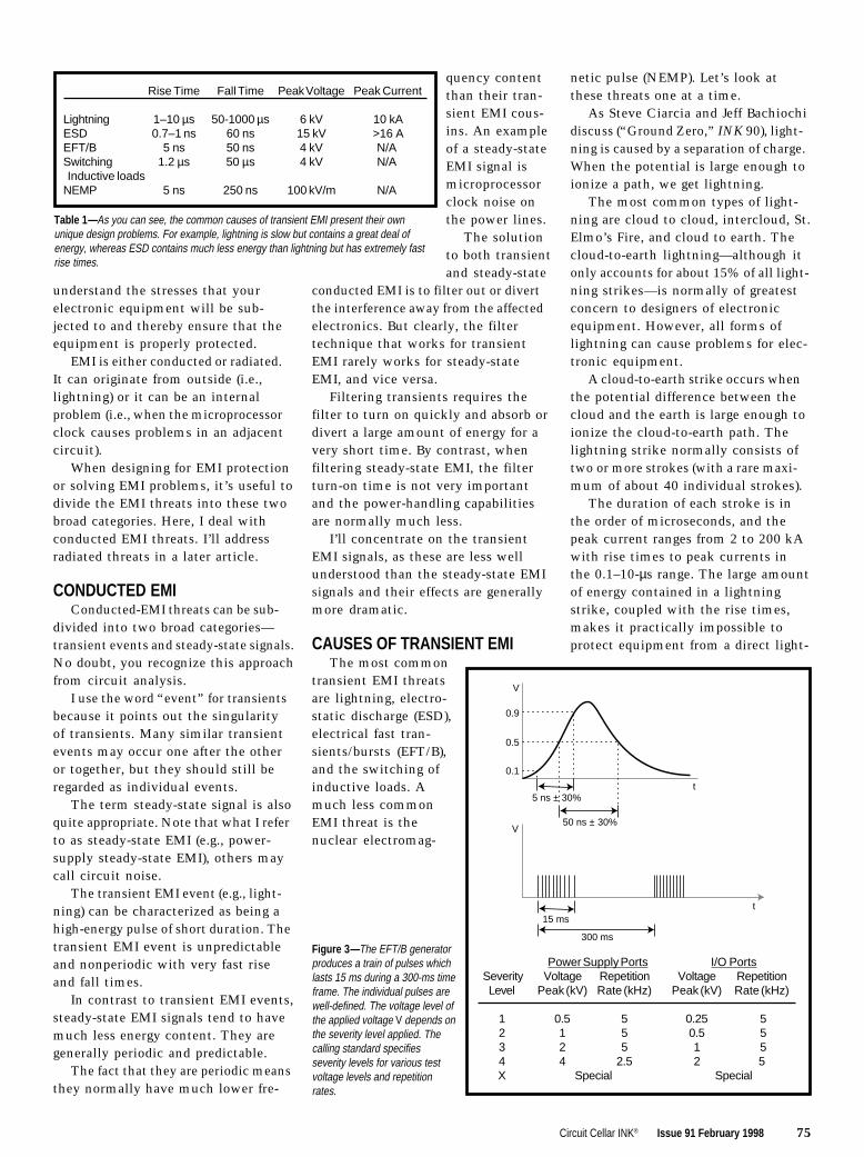
Circuit Cellar INK® Issue 91 February 1998 75
understand the stresses that yourelectronic equipment will be sub-jected to and thereby ensure that theequipment is properly protected.
EMI is either conducted or radiated.It can originate from outside (i.e.,lightning) or it can be an internalproblem (i.e., when the microprocessorclock causes problems in an adjacentcircuit).
When designing for EMI protectionor solving EMI problems, it’s useful todivide the EMI threats into these twobroad categories. Here, I deal withconducted EMI threats. I’ll addressradiated threats in a later article.
CONDUCTED EMIConducted-EMI threats can be sub-
divided into two broad categories—transient events and steady-state signals.No doubt, you recognize this approachfrom circuit analysis.
I use the word “event” for transientsbecause it points out the singularityof transients. Many similar transientevents may occur one after the otheror together, but they should still beregarded as individual events.
The term steady-state signal is alsoquite appropriate. Note that what I referto as steady-state EMI (e.g., power-supply steady-state EMI), others maycall circuit noise.
The transient EMI event (e.g., light-ning) can be characterized as being ahigh-energy pulse of short duration. Thetransient EMI event is unpredictableand nonperiodic with very fast riseand fall times.
In contrast to transient EMI events,steady-state EMI signals tend to havemuch less energy content. They aregenerally periodic and predictable.
The fact that they are periodic meansthey normally have much lower fre-
quency contentthan their tran-sient EMI cous-ins. An exampleof a steady-stateEMI signal ismicroprocessorclock noise onthe power lines.
The solutionto both transientand steady-state
conducted EMI is to filter out or divertthe interference away from the affectedelectronics. But clearly, the filtertechnique that works for transientEMI rarely works for steady-stateEMI, and vice versa.
Filtering transients requires thefilter to turn on quickly and absorb ordivert a large amount of energy for avery short time. By contrast, whenfiltering steady-state EMI, the filterturn-on time is not very importantand the power-handling capabilitiesare normally much less.
I’ll concentrate on the transientEMI signals, as these are less wellunderstood than the steady-state EMIsignals and their effects are generallymore dramatic.
CAUSES OF TRANSIENT EMIThe most common
transient EMI threatsare lightning, electro-static discharge (ESD),electrical fast tran-sients/bursts (EFT/B),and the switching ofinductive loads. Amuch less commonEMI threat is thenuclear electromag-
netic pulse (NEMP). Let’s look atthese threats one at a time.
As Steve Ciarcia and Jeff Bachiochidiscuss (“Ground Zero,” INK 90), light-ning is caused by a separation of charge.When the potential is large enough toionize a path, we get lightning.
The most common types of light-ning are cloud to cloud, intercloud, St.Elmo’s Fire, and cloud to earth. Thecloud-to-earth lightning—although itonly accounts for about 15% of all light-ning strikes—is normally of greatestconcern to designers of electronicequipment. However, all forms oflightning can cause problems for elec-tronic equipment.
A cloud-to-earth strike occurs whenthe potential difference between thecloud and the earth is large enough toionize the cloud-to-earth path. Thelightning strike normally consists oftwo or more strokes (with a rare maxi-mum of about 40 individual strokes).
The duration of each stroke is inthe order of microseconds, and thepeak current ranges from 2 to 200 kAwith rise times to peak currents inthe 0.1–10-µs range. The large amountof energy contained in a lightningstrike, coupled with the rise times,makes it practically impossible toprotect equipment from a direct light-
Rise Time Fall Time Peak Voltage Peak Current
Lightning 1–10 µs 50-1000 µs 6 kV 10 kAESD 0.7–1 ns 60 ns 15 kV >16 AEFT/B 5 ns 50 ns 4 kV N/ASwitching 1.2 µs 50 µs 4 kV N/A Inductive loadsNEMP 5 ns 250 ns 100 kV/m N/A
Table 1—As you can see, the common causes of transient EMI present their ownunique design problems. For example, lightning is slow but contains a great deal ofenergy, whereas ESD contains much less energy than lightning but has extremely fastrise times.
V
0.9
0.5
0.1
5 ns ± 30%t
50 ns ± 30%V
t15 ms
300 ms
Power Supply Ports I/O PortsSeverity Voltage Repetition Voltage RepetitionLevel Peak (kV) Rate (kHz) Peak (kV) Rate (kHz)
1 0.5 5 0.25 52 1 5 0.5 53 2 5 1 54 4 2.5 2 5X Special Special
Figure 3 —The EFT/B generatorproduces a train of pulses whichlasts 15 ms during a 300-ms timeframe. The individual pulses arewell-defined. The voltage level ofthe applied voltage V depends onthe severity level applied. Thecalling standard specifiesseverity levels for various testvoltage levels and repetitionrates.

76 Issue 91 February 1998 Circuit Cellar INK®
Figure 4 —Using the schematic of an ESD gun (Figure 2, INK 81, p. 63), we can calculatethe voltage and currents resulting from an ESD event. Here, an RS-232 input with an inputimpedance of about 8 kW is subjected to a 15-kV ESD. The result is virtually the full 15 kVappearing across the input.
ning strike. Thankfully,direct strikes are rare.
Of greater concern todesigners of electronicequipment are indirectlightning strikes. Withabout 100 cloud-to-earthstrikes every secondworldwide, chances areyour equipment will besubject to indirect light-ning strikes.
Unfortunately, when it comes tolightning strikes, defining the hazard isvery difficult. Of course, we mustcome up with waveforms that definethe transients that lightning produces.However, it’s important to keep inmind their limitations and to under-stand that the test waveforms dependto some extent on your equipment.
Why are transients induced by light-ning so hard to define? First, lightningis a natural phenomenon that occursin an environment—outdoors—thathas a great many variables. Therefore,quantifying lightning is difficult.
Note the values I gave above forlightning: peak current of 2–200 kAand a rise time of 0.1–10 µs. These arehardly ranges you can plug into yourcircuit-analysis program.
Another reason it’s difficult todevelop lightning transient waveformsis that the coupling path is unpredict-able. Lightning can couple into a net-work via direct conduction or indirectconduction, where lightning induces avoltage on a wire that then conductsit into a circuit or system.
When lightning is directly coupledin, you can usually identify the entrypoint (e.g., a power cable or I/O line) butit’s difficult to quantify the couplingpath. When the lightning transient iscoupled in via indirect conduction, thebest you can do to quantify the couplingpath is to say the farther away thestrike, the better.
As a general rule of thumb, a light-ing strike 1 km away from a 1-m pieceof bare wire induces a voltage of 100 Vacross the wire. Since propagation isthrough the air, coupling behaves as asquare law.
Without exact knowledge of thesource or coupling path, it’s difficult tocome up with test waveforms that simu-
This is known as theturboelectric effect.
The most commoncause of ESD is humanscoming in contact withelectronic equipment.When the charged bodycomes in contact with aconducting path (e.g.,electronic equipment),an ESD event occurs.
As you may recall, oneof the immunity tests is the ESD test,in which the equipment under test issubjected to a simulated ESD withvaried levels of severity. Figure 2 (repro-duced from INK 81, p. 63) shows thetransient waveform associated withESD and gives typical specifications.Note that the energy contents are muchless than that of a lightning transient,but the rise and fall times are muchfaster (i.e., in the nanosecond range).
Arcing-type surge protectors, suchas gas discharge devices, are too slowfor ESD events. Generally, metal oxidevaristors (MOVs) along with transientvoltage suppressor (TVS) semiconduc-tors protect against ESD.
EFT/BElectrical fast transients or bursts
are usually caused by the repetitiveswitching of inductive loads. The indus-try standard for EFT/B waveforms isshown in Figure 3 (reproduced fromINK 81, p. 68).
MOVs and TVS semiconductorsprotect from EFT/B. For more informa-tion on EFT/B and ESD, please refer to“Standards for Electromagnetic Com-pliance Testing—Part 3: Immunityand Susceptibility” (INK 81).
SWITCHED INDUCTIVE LOADSThe switching of inductive loads is
a special case of the EFT/B where thetransient is a single event rather thana burst, as shown in Figure 3. Whenthe current flowing through an induc-tive load is interrupted, a transientvoltage is produced by the collapsingmagnetic field.
These loads are everywhere (e.g.,refrigerators, air conditioners, motors,etc.). The voltage is characterized by:
V = –Ldidt
late transients caused by lighting. How-ever, industry and standards groupshave done a good job of creating usefultest waveforms, which are based onobservation as much as calculation.
Several industry-standard wave-forms model lightning-induced surges.Virtually every one of these waveformsis based on the double-exponentialwaveform (see Figure 1).
The double-exponential waveform ischaracterized by an exponential risefrom 10% to 90% of the peak and anexponential decay to 50% of peak. Themost commonly used waveforms arethe 8/20-current and the 1.2/50-volt-age waveforms. The first number isthe rise time, and the second numberis the decay time in microseconds.
Lightning is modeled as a short-circuit event with a peak current up to10 kA or as an open-circuit event withpeak voltages up to 6 kV. The peakvoltage of 6 kV is the point at whichmost household receptacles flash over.
Other standard double-exponentialwaveforms are the 10/1000 and 10/700most commonly used in telecom appli-cations. The European Community uses1.2/50 for power lines and 10/700 fortelecom lines to describe the transientthreat posed by lightning (see 1000-4-5).
Voltages for these waveforms rangefrom 500 to 4000 V. Depending on theclass of equipment and peak currents,voltages can be as high as 1 kA.
As transients go, lightning is arelatively slow event and is normallyhandled using air or carbon spark gapsor gas discharge devices.
ESDElectrostatic-charge buildup is
caused when two nonconducting objectscome in contact and then separate,one gaining and one losing electrons.

Circuit Cellar INK® Issue 91 February 1998 77
where V is the induced voltage, L isthe inductance, and di/dt is the cur-rent’s rate of change.
The industry standard for a switchedinductive load is the 1.2/50 doubleexponential shown in Figure 1, withvoltage peaks in the 0.5–6-kV rangedepending on the class of instrument.
Keep in mind that the point atwhich the current is switched is alsoimportant. If the current is switchednear the zero crossing, much lessvoltage is induced than if the currentwere switched near the peak of thevoltage waveform. This fact is impor-tant if you have any control over theswitching of the inductive load.
Once again, MOVs and TVS semi-conductors are the normal method ofprotection.
NUCLEAR EM PULSEA nuclear electromagnetic pulse
(NEMP) is, thankfully, not a commonEMI threat and is therefore not ofconcern to most designers. However,NEMPs are of great concern to thedesigners of military equipment.
When a nuclear device explodes, itcreates an impulse of electromagneticenergy. The pulse rise time is in the5-ns range with a pulse duration of~250 ns.
The pulse produces fields in the100-kV/m range, which of course, hasdevastating effects on most electronics.This concept was used in the movieBroken Arrow.
TRANSIENT THREATSTable 1 summarizes the most com-
mon transient-producing EMI threats.As you can see, every EMI transientthreat presents its own special prob-lems to designers.
Lightning is a relatively slow tran-sient threat, but it has a great amountof energy. On the other hand, an ESDhas a very small amount of energy,but its rise time is extremely fast.
It’s important to keep in mind thatthe characteristics of the transientevent—the current and voltage ampli-tudes, rise and fall times, and duration—depend as much on the characteristicsof the affected equipment as on thesource of the transient and the cou-pling path.
Telecom applications generally usea 10/100 or 10/700 double exponen-tial, rather than the more common8/20 or 1.2/50 waveform. This is dueto the nature of telecommunicationsnetworks, which tend to distributethe transient over many lines, therebyreducing its rise time and increasingthe decay time.
Now that you’ve seen the waveformsof the most common EMI transients,a useful experiment would be to applythese waveforms to your circuit with-out protective devices and calculatethe voltage and current levels.
Figure 4 shows a circuit that simu-lates an ESD being applied to an RS-232input. The input impedance of the lineis about 8 kΩ (assuming input capaci-tance and lead inductance are zero).
If you assume contact resistance iszero, the result, using the voltagedivider rule, would most likely be thedestruction of the RS-232 input. Al-though this example was very simple,with the addition of a little moredetail, this technique is a powerfuldesign tool.
Now that you have a feel for thetransient threats that your equipmentwill encounter, we can turn our atten-tion to protecting circuits. In theupcoming months, I’ll discuss thecomponents used to protect equipmentfrom EMI transients. I
Joe DiBartolomeo, P. Eng., has over15 years’ engineering experience. Hecurrently works for Sensors and Soft-ware and also runs his own consult-ing company, Northern EngineeringAssociates. You may reach Joe [email protected] or by telephoneat (905) 624-8909.
REFERENCES
Encyclopedia International, Vol.10, Grolier, New York, NY, 1972.
MTL, Surge-Protection App note,1993–1994.
MTL, App note AN9009, 1990.KeyTek, Surge-protection test hand-
book, 1986.
I R S425 Very Useful426 Moderately Useful427 Not Useful

78 Issue 91 February 1998 Circuit Cellar INK®
FROM THEBENCH
Jeff Bachiochi
e
Choose the Right VehicleBefore Riding the Air Waves
Evenwith allthe TVs,tapes,CDs, and
VCRs, radio stillpersists. Jeff takes alook at dual-statemodulationtechniques to helpyou ensure that yourmessage getsthrough.
veryone has theirfavorite. Chances
are, either yours haschanged format over the
years or your tastes have changed. Yet,we all still listen to that old mediumthat just won’t quit—radio.
It was comforting growing up withyour favorite station. That special DJwas like a good friend you could alwayscount on.
Even with the availability of cas-settes, CDs, TVs, and VCRs, radiocontinues to be a popular medium. Andnow, talk radio has its own following.Radio just won’t die.
AM VS. FMFor a signal to be transmitted and
received over a particular medium,the characteristics of the signal needto be modulated or changed.
Our vocal cords modulate the air,creating air-pressure waves that traveloutward from our mouths. If thesewaves happen to enter our ear’s cavityand in turn vibrate the eardrum, thepressure waves are demodulated intothe original signal.
We can control the amplitude oroverall amount of the air pressure.Loud sounds have large pressure waves,and quiet sounds have smaller pres-sure waves.
And, we can control the frequencyof air-pressure waves. Low frequencies
produce waves stretched apart, whilehigher frequencies create waves thatare packed closer together.
Our vocal cords modulate air usingboth AM (amplitude modulation) andFM (frequency modulation). I coulduse the term AM (angular modulation)instead of FM, but it gets too confusing.
Angular modulation can be eitherfrequency or phase modulation. Fre-quency modulation changes the car-rier’s frequency in direct proportion tothe modulation’s amplitude. Phasemodulation (PM) changes the carrier’sphase in direct proportion to the modu-lation’s amplitude.
These differences are subtle. The FMcarrier is at its maximum frequencydeviations during the maximum andminimum amplitudes of the modula-tion signal. The PM carrier is at itsminimum frequency deviations dur-ing maximum and minimum ampli-tudes of the modulation signal.
Since both FM and PM carriershave the same spectral properties, I’lluse FM, one form of angular modula-tion, to lessen the confusion with AM(amplitude modulation).
AUDIO VS. DATAAM and FM radio broadcasts are
forms of analog modulation. WhenAM and FM are used for data trans-mission, the modulation format canbe simplified.
AM becomes a carrier-present/carrier-absent function, where thepresence of the carrier indicates onedata state and the absence equals theopposite state.
FM can have two states as well,but a carrier is always present. UsingFM, the two states are two frequenciesequidistant from the original carrier—one above it and the other below.
Data transmission over the perfectmedium (or close to it), a LAN, orphone line often uses multilevel modu-lation (i.e., four or more states, insteadof two) to double the data transmittedin one bit time.
Both AM and FM can even be usedtogether to increase the data/bit time.That’s how we can get more and morethroughput using the same antiquatedPOTS (plain old telephone service)delivery service.

Circuit Cellar INK® Issue 91 February 1998 79
Improving technologies enable usto get better at detecting multileveltransmissions. In this discussion, Iwon’t delve into these more complexmodulations.
Instead, I concentrate on a moreerror/interference-prone transmissionmedium—radio. And, I will compareonly the simplest dual-state modula-tion techniques.
ASK VS. SPECTRUMAmplitude Shift Keying (ASK) was
first used commercially by Marconi in1896, when his Wireless TelegraphCompany established the world’s firstpermanent wireless installation at TheNeedles on the Isle of Wight, Hamp-shire, England.
Marconi used Morse code, devel-oped earlier by Samuel Morse, to sendwireless messages. (Actually, Morseamplitude modulated current flow inhis telegraph system, but the mediumwas copper wires.)
The maximum modulation rate isgenerally a factor of 10–100 times lessthan the carrier frequency. The upperdata rate for the AM radio band isabout 15 kHz, and the lowest AMcarrier is 36 times that (i.e., 540 kHz).
As audio modulates a carrier, upperand lower sidebands are created andtransmitted along with the carrier.These sidebands are spaced at a devia-tion from the carrier equal to that ofthe modulation frequency, where:
sidebandf = carrierf ± modulationf
as you see in Figure 1a.When audio modulates a carrier
between 0 and 100%, the sidebandsincrease in amplitude in relation tothe percentage of modulation from no
sidebands, at 0% modulation, to halfthe carrier amplitude, at 50% modula-tion (compare Figures 1a and 1b).
When data is transmitted using ASKmodulation, no sidebands are createdsince the modulation varies between0% and no carrier (see Figure 1c).Receivers require only a narrow band-pass filter. However, in-band noisehas a large effect on the signal since itis playing one-on-one with the carrier.
FSK VS. SPECTRUMFrequency modulation became a
commercial institution in 1940 whenZenith Radio’s Eugene McDonaldstarted an FM radio station. However,it was Edwin H. Armstrong who firstdemonstrated FM’s superior static-freeradio reception.
Unlike AM, where legal modulationis between 0 and 100%, FM is expressedas a modulation index or the ratio ofpeak frequency deviation to modula-tion frequency.
As the amplitude of the modulationincreases, the frequency deviation(and the modulation index) increaseswith respect to the modulation fre-quency, moving the sidebands furtherfrom the unmodulated carrier (seeFigures 2a and 2b).
As the modulation frequency falls,the sidebands become rich in over-tones. Remember, in FM, the centerfrequency (or unmodulated carrier) isnot part of the FM transmission, un-less of course, there is no modulation.
Unlike AM, where the total powertransmitted was proportional to thedata, the total power with FM is alwaysthe same. FM’s change is one of side-band deviation.
In FM data transmission, this changeconsists of a increase or decrease in theovertones of the sidebands sharing thetransmitted power.
POWER RESTRICTIONThe FCC regulates all radio-fre-
quency (RF) devices.RF devices are defined as “…any
device which in its operation is ca-pable of emitting radio-frequencyenergy by radiation, conduction, orother means,” whether it be inciden-tal, unintentional, or intentionaltransmissions. Part 15 of the FCCregulations explains the conditionsunder which devices can be operated,licensed, and unlicensed.
Among the regulations is the defini-tion of digital devices (formerly labeledcomputing devices) as a “…(device or
EmaxEc
Emin
m = 0.2
Ec
EusbElsb
fc fc + fmfc – fm
Emax
Ec
Emin
m = 0.7
Ec
EusbElsb
fc fc + fmfc – fm
EmaxEcEmin
m = 0
Ec
EusbElsb
fc fc + fmfc – fm
a) b) c)
m = 7.0
fc fc + 9fmfc – 9fm
a) b)
m = 2.0
fc fc + 9fmfc – 9fm
Figure 2a —In FM, large modulation amplitudes move sidebands further from center frequency, while small modulation amplitudes (b) require less bandwidth.
Figure 1 —The amount ofamplitude modulationaffects the amplitude ofthe sidebands and not thatof the carrier. At 30%modulation, the sidebandsare small (a), while at 70%,the sidebands are large(b), and at 0%, there areno sidebands (c).

80 Issue 91 February 1998 Circuit Cellar INK®
system) which generates and uses tim-ing signals or pulses at a rate in excessof 9000 pulses (cycles) per second.”
Also of note is the ever-popularelectronics kit, described as “any num-ber of electronic parts, usually providedwith a schematic diagram or printedcircuit board, which, when assembledin accordance with instructions, results
in a device subject to the regulationsof this Part, even if additional parts ofany type are required to complete theassembly.”
Part 15 characterizes intentionalradiators as those devices that emitradio-frequency energy. And, RF energyis defined as electromagnetic energyat any frequency in the radio spectrum
between 9 kHz and 3,000,000 MHz.That just about covers everythingwe’d be talking about, huh?
Subpart B of Part 15 discusses unin-tentional radiators. That’s where mostdevices and appliances fit (see Table 1afor the band vs. field-strength limits).
Subpart C reviews intentionalradiators (i.e., transmitters), and theserange from 9 kHz to well over 38 GHz.Within this range, there are manybands in which only spurious emissionsare permitted, and radiated energymust fall within strict guidelines.
Table 1b lists the bands limited tothese transmissions. For continuousoperation, the bands are even morerestricted (see Table 1c).
So, you can see that field strengthisn’t the only limitation put on atransmitter. The type transmissionsare also restricted to certain bands.This means if you intend to operatean unlicensed transmitter, you needto identify where you fit in the FCC’sregulations before you can determinewhat transmitter frequencies are avail-able to you.
Frequency Unintentional Radiators of Emission (Class A digital device)
9–490 kHz 2400 µV/m490 kHz–1.7 MHz 24000 µV/m
1.7–30 MHz 30 µV/m30–88 MHz 90 µV/m88–216 MHz 150 µV/m216–960 MHz 210 µV/m
960+ MHz 300 µV/m
Table 1—Part 15 regulates maximum allowable emissions based on the signal types of unintentional radiators (a),intentional spurious radiators (b), and intentional continuous radiators (c).
a) b)
c)
Frequency Intentional Spuriousof Emission Radiators
40 MHz 225 µV/m70–130 MHz 125 µV/m130–174 MHz 125–375 µV/m174–260 MHz 375 µV/m260–470 MHz 375–1250 µV/m
470+ MHz 12,500 µV/m
Frequency Continuous Intentional Continuous Intentionalof Emission Radiators (Fundamental) Radiators (Harmonics)
902–928 MHz 50 mV/m 500 mV/m2400–2483 MHz 50 mV/m 500 mV/m5725–5875 MHz 50 mV/m 500 mV/m
24+ GHz 250 mV/m 2500 mV/m

Circuit Cellar INK® Issue 91 February 1998 81
I R S428 Very Useful429 Moderately Useful430 Not Useful
REFERENCES
TextAmerican Radio Relay League, The
Radio Amateur’s Handbook,Newington, CT, 1998.
FCC, Code of Federal Regulations,Title 47, Part 15, 1995.
InternetSpectrum Analysis, Amplitude &
Frequency Modulation, Test &Measurement App note 150-1,www.tmo.hp.com
williams.cs.ncat.edu/modulate.htmrobotics.eecs.berkeley.edu/~sastry/
ee20/modulation.htmlwww.physics.udel.edu/wwwusers/
watson/student_projects/scen167/thosguys
Jeff Bachiochi (pronounced“BAH-key-AH-key”) is an electrical engineer onCircuit Cellar INK’s engineering staff.
His background includes product designand manufacturing. He may be reachedat [email protected].
Why am I talking about the FCCregulations when I started off talkingabout AM and FM?
First, it’s important to realize thatyou just can’t arbitrarily choose anytransmission frequency if you wantyour product to be legal. Second, be-cause the FCC regulations have radi-ated-energy limits, the transmissiondistance depends on the type of trans-mission modulation you plan to use.
So, let’s wrap this up by looking atthe advantages and disadvantages ofAM and FM.
Advantages Disadvantages
AM lower cost lower data ratelower power consumption poor noise immunitysmaller size noncontinuous carrierpotentially twice the allowable output power
FM higher data rate higher costbetter noise immunity higher power consumptioncontinuous carrier larger size
lower allowable power output
Table 2—AM and FM techniques should be considered based on need sinceeach has its own advantages or disadvantages.
WHICH WAY?Like anything else
in life, it’s one bigtradeoff. If the low-est cost, power con-sumption, and/orsize is the ultimategoal, then AM lookslike the best choice(see Table 2).
However, if ahigher data rate and/or better noise immu-nity is of the utmost
importance, then it might be better togo with FM. Then again, if it’s notlegal, it doesn’t matter much, does it?
The moral is, when you think youfound the solution, make sure to checkthe regulations. After all, while itmight seem as if the FCC’s sole pur-pose is to make life miserable, really,they’re just here to protect us fromeach other. I

82 Issue 91 February 1998 Circuit Cellar INK®
SILICONUPDATE
Tom Cantrell
t
Double-Duty DSP
Whatfirstappearsas justanother
DSP turns out to bemuch more. Zilog’sZ89xx3 DSP offersthe usual DSP goodsand acts like manyhighly integratedcontrollers for afraction of the cost.
he earnest mar-keting fellow from
Zilog didn’t get morethan a few foils into his
presentation about their DSP to Kenand me before I butted in.
I’m definitely a left-coast kind of guy(er, dude). You may think you’re givingme a presentation, but I see every meet-ing as a potential rap session. Mean-while, Ken is one of those New England“salt of the earth” types who use wordssparingly, as if stocking up for winter.
Anyway, the poor Zilog fellow saidsomething about RISC and DSP that
convinced me my comments would,or at least should, be welcomed. Isuppose my two cents could have beenhelpful, but I have to admit I ran upthe tab to at least a quarter.
Eventually realizing I was chewingup the allotted meeting time at a prodi-gious rate, I finally deigned to allowthe poor guy to rush through the restof his pitch. The usual stuff aboutMIPS and MACs, high performance,low cost, and so on. To tell the truth,I was already mentally filing under“Yet Another DSP.”
Ken hadn’t said much during themeeting—not that he could have got-ten a word in edgewise. It was only aswe were leaving and I mentioned mysomewhat ho-hum assessment thatKen finally spoke, “You know, theremight be something to that.”
DSP STEREO(TYPING)It was one of those moments that
prompts a breakthrough in self-aware-ness. I realized I was guilty of the samesin of conventional wisdom compla-cency that I always warn against.
In the CPU versus DSP debate, I’vebeen inspired by the work of professorMichael Smith. He demonstrated wayback in ’92 (including “To DSP or Notto DSP,” INK 28) that a decent CPU-pipelined Harvard RISC enhancedwith key DSP features (e.g., fast mul-tiplier) could match the signal-process-ing performance of DSPs.
Photo 1a —Whether the new Zilog ’x3 is a DSP or a micro, you’ve still got to hook it up and get it working. Zilogoffers a low-cost evaluation and emulation board that connects to a PC via a serial port and includes an OTPprogrammer.

Circuit Cellar INK® Issue 91 February 1998 83
Today, you needn’t look furtherthan your own desktop, where MMXand similarly pumped CPUs crunchthrough audio, image-processing,compression, and modem algorithmsformerly deemed the province of DSPs.
Reinforcing my bias, I had a numberof negative conceptions about DSPs.Pricey, hard to program and debug, weakhandling anything besides DSP loops,finicky hardware interface, and so forth.
Ken’s comment prompted me tostick to my own advice: Questionauthority, including your own. If CPUsare becoming more like DSPs, doesn’tthat mean DSPs are automaticallybecoming more like CPUs? I decidedto give the Zilog Z89xx3 16-bit single-chip DSP a closer, and impartial, look.
Even without popping the hood, aglance at the sticker dispels pricemisconceptions. Though high-endDSPs that I’ve covered in the past(like Analog Device’s SHARC andTI’s VelociTI) come with double- oreven triple-digit price tags, the Zilogparts are less than $10 for low-volumeOTPs and dive below $5 for high-volume masked ROMs.
TWO CHIPS IN ONEAlong with the price tag, the ’x3
block diagram in Figure 1 furtherhighlights the similarity with main-stream MCUs. Certainly nothing odd
about the ADC, counter/timers, SPI,parallel I/O, and expansion bus.
Indeed, the high-speed multiplier anddual data RAMs are the only distinctlyDSP features. They’re also the focalpoint for critical design tradeoffs thatachieve good performance at such alow price.
For instance, 16-bit operands wouldnormally call for a 32-bit ALU andaccumulator to avoid overflow. How-ever, when determining the resolutionrequired, consider the source—mostlikely an on-chip four-channel eight-bit ADC.
No sense demanding accuracybeyond the precision of the input. So,instead of a full 32-bit result, the ’x3only totes the most significant 24 bits.
Though the 24-bit fractional format(i.e., sign bit followed by fractional
power of two bits, such as 1⁄2, 1⁄4, 1⁄8…)can’t represent 1.0, it gets darn closewith 0.9999999. Furthermore, 8-bit dataand 24-bit resolution mean we can mul-tiply and accumulate up to 256 samplesbefore worrying about overflow, whichjust happens to perfectly match the256-word depth of the data RAMs.
Similar economizing takes place onthe shifter front. Instead of the fullbarrel shifter found on expensive chips,the ’x3 gets by with conventionalsingle-bit left and right shifts, supple-mented by a three-bit right-shift option.Of course, simply multiplying by theappropriate fractional power of twoduplicates the function of the right-shift portion of a barrel shifter (e.g.,multiply by 1⁄32 to shift right five bits).
Remember that clever design mayoffset left-shift laments. For instance,one Zilog app note discusses connectinga single eight-bit SRAM to the 16-bitexpansion bus. Since the chip has nobuilt-in bus matching or sizing capabil-ity, this calls for software to morph16-bit transfers into dual-byte accesses.It seems there’s no escape from chuggingthrough eight left-shift instructions.
The trick? Connect the SRAM toevery other expansion-bus bit, and asingle shift is all it takes to switchbetween the even and odd bits.
LINGUA FRACTALAs with the block diagram, only a
small portion of the architecture (seeTable 1) uniquely brands the ’x3 as aDSP, most notably the one-clock multi-ply (MLD), multiply and accumulate(MPYA), and multiply and subtract (MPYS)instructions.
There’s also a bit of looping supportwith the Loop address-mode option
Port 0*EXTENEA0–2EXT0–15/P00–15*DSRD/*WR
AN0AN1AN2AN3
Port 1P10–17orINT2CLKOUTSINSOUTSKSSU10–1
Port 2P20–27ORU12TMO01,10TMO2INT0–1*WAIT
Port 3P30–33P34–37
*HALT
ROMEN
*RES
CLK1
CLK0
AGND
ANVCC
VAL0
VAH1
LPF
VSS
VDD
PD0–15
PA0–15
*PAZ
PDATA
PADDR
ProgramROM/OTP8192 × 16
Data RAM0256 × 16
P0 P0P1 P1P2 P2
D P0–3 D P4–6
ADDR ADDRGEN0 GEN1
Data RAM1256 × 16
X YMultiplier
P
Shifter
ArithmeticLogic Unit
(ALU)
Accumulator
16-Bit TimerCounter
16-Bit TimerCounter, PWM
16-Bit TimerCounter, PWM
SPI
4 Inputs4 Outputs
8-Bit I/O
8-Bit I/O
8-BitADC
16-BitProgram
I/O
ProgramControl
Unit
SwitchDDATA
Stack
Figure 1 —The ’x3 surrounds the core of a DSP(high-speed multiplier, dual-bank RAM, and sepa-rate instruction and data buses) with traditionalcontroller peripherals (PIO, timer/counters, ADC,and SPI).
Figure 2 —The ’x3clock generator is aboutas good as it gets,certainly far superior tothe plain oscillator foundon most controllers.
LPF
PhaseDetector
8-BitDivider
VCO
STOP_VCO
:2:2
ClockSync
Switch SystemClock
32 kHz
STOP_OSC
PLLDivider
Bank 15/Ext15
Clock Source
BYPASS_PLL
Off-Chip
0.1 µF22 µF
1 kΩ
:2
On-Chip
0 [15–
8]
1 4–3
2

84 Issue 91 February 1998 Circuit Cellar INK®
Table 1a & b —The speedy multiply and program memory address modes are the only clues that the ’x3 is a DSP.c—The instruction set is quite terse, indeed more “reduced” than that of many RISCs.
that tweaks conventional pointer auto-increment and -decrement with modulorollover. Cost consciousness dictatesa bit of a compromise. That’s why onlypower-of-two loop sizes between 2and 256 are supported.
Since the ’x3 is a true Harvardarchitecture, the <memind> address-ing mode is provided to access data(e.g., constants, tables, and coefficients)stored in program (EP)ROM.
Other than these overtly DSPishfeatures, there’s little to distinguishthe ’x3 from conventional controllers.It has kind of a “Z8 on steroids” flavor(in fact, the $99 assembler offered byZilog supports both the Z8 and ’x3).Otherwise, it’s business as usual (e.g.,LD, JP, CALL, AND, OR, etc.).
Of course, the ’x3’s claim to fameis that most of the instructions aresingle word and execute in a singleclock. Two exceptions are when thelong (16 bit) immediate (two word, twoclock) and indirect (one word, threeclock) address modes are used. Sincethey’re relatively rarely encountered,that leaves two clock branching (i.e.,JPs, CALLs, RETs) as the main MIPSversus megahertz derater.
JPs and CALLs are conditional, buttiming is the same whether the branchis taken or not. Besides the usual flags(Z, C, OV, etc.), two pins (UI0 and UI1)and their inversions are patched intothe condition codes. The ’x3 alsosupports conditional execution fortypical accumulator operations (INC,DEC, NEG, shifts, and rotates), cuttingthe number of JPs required.
The interrupt scheme furthers thecause of fast and predictable response.It isn’t fancy, mind you. No intricateprogrammable priority or nestingschemes, and the stack is just six deep.However, it only takes two clocks (aftercompleting the current instruction) tosave the PC and vector to the handler.
All interrupt sources (including on-chip I/O and three external program-mable edge inputs) are mapped to oneof three internal interrupt vectors. Theidea is to pick the two most criticalinterrupt sources and map them tovectors 0 (highest priority) and 1.
Then, any or all of the remainingsources are assigned to vector 2 (low-est priority), recognizing some polling
Symbolic Name Syntax Description
<pregs> Pn:b Pointer Register<dregs> Dn:b Data Register
(points to RAM)<hwregs> X, Y, PC, SR, P Hardware Registers
EXTn, A, BUS<accind> @A Accumulator Memory Indirect(points to
Program Memory)<direct> <expression> Direct Address Expression<limm> #<const exp> Long (16 bit) Immediate Value<simm> #<const exp> Short (8 bit) Immediate Value<regind> @Pn:b Pointer Register Indirect
(points to RAM) @Pn:b+ Pointer Register Indirect with Increment@Pn:b–LOOP Pointer Register Indirect with Loop Decrement@Pn:b+LOOP
<memind> @@Pn:b Pointer Register Memory Indirect (points to @Dn:b Data Register Memory Indirect
Program Memory) @@Pn:b–LOOP Pointer Register Memory Indirect with Loop Decrement@@Pn:b+LOOP Pointer Register Memory Indirect with Loop Increment@@Pn:b+ Pointer Register Memory Indirect with Increment
Register Description
P Multiplier output (24 bit)X X multiplier input (16 bit)Y Y multiplier input (16 bit)A Accumulator (24 bit)
SR Status register (16 bit)Pn:b Six RAM address pointers (8 bit)PC Program counter (16 bit)
EXT0 External data port 0 (16 bit)
Instruction Description
ABS Absolute valueADD AdditionAND Bitwise ANDCALL Subroutine callCCF Clear carry flagCIEF Clear interrupt enable flagCOPF Clear overflow protect flag
CP CompareDEC DecrementINC IncrementJP JumpLD Load
MLD MultiplyMPYA Multiply addMPYS Multiply subtract
a)
b)
c)
EXT1 External data port 1 (16 bit)EXT2 External data port 2 (16 bit)EXT3 External data port 3 (16 bit)EXT4 External data port 4 (16 bit)EXT5 External data port 5 (16 bit)EXT6 External data port 6 (16 bit)EXT7 External data port 7 (16 bit)
Register Description
NEG NegateNOP No operationOR Bitwise OR
POP Pop stackPUSH Push stackRET Subroutine returnRL Rotate leftRR Rotate rightSCF Set carry flagSIEF Set interrupt enable flagSLL Shift left logical
SOPF Set overflow protection flagSUB SubtractXOR Bitwise XOR
Instruction Description
will be required if more than one isenabled. Any source that isn’t assignedto one of the three internal vectors isde facto disabled.
MY KINGDOM FOR A CLOCKBefore going further, I’d like to
single out the ’x3 clock generator,shown in Figure 2, for special praise.Often overlooked, clocking is a keyissue with intrinsic relation to systemcost, reliability, power consumption,EMI, and timing capability.
Zilog could have gotten by with theconventional crystal oscillator, since20 MHz arguably doesn’t push the enve-lope. Nevertheless, they went to thetrouble of providing a PLL-based clockgenerator that works with a cheap,rugged, low-EMI 32-kHz watch crystal.While the ’x3 isn’t the first (and won’tbe the last) to exploit PLL, Zilog’s designis notably pragmatic and versatile.
As shown in Figure 3, a variety ofdynamically programmable optionscomprise a four-tier low-power regime.

Circuit Cellar INK® Issue 91 February 1998 85
The most miserly Stopclock mode shuts every-thing down.
However, those who’vedealt with PLLs beforeknow that slow wakeupis the price to pay fordeep sleep. The ’x3 is noexception, needing aleisurely 10 ms to get upand running.
If that’s a problem,select the option thatleaves the PLL running for fast recovery.Another choice has the ’x3 run directlyoff the 32-kHz crystal, again with orwithout the fast-recovery option. Noticethe selection of wakeup sources, includ-ing INT0, the SPI SS (Slave Select), aPIO bit (U10), or all three.
KITCHEN SINKThe ’x3 may be brainy, but does it
have the I/O brawn to match highlyintegrated controllers? Though the chiphas a complete selection of peripherals,the devil may be in the details, so let’stake a closer look.
The ’x3 is offered in five differentpackages (listed in Table 2), which basi-cally fit into two categories—big (68+pins) and small (44 pins). Though the100-pin version does offer 64K wordprogram expansion, it’s the 16-bit EXT(external) bus that’s intended to accom-modate application-specific add-ons.
The three-address-line limit (EA0–2) isn’t simply a case of pin shortage.In fact, EXT0–EXT7 are all the ’x3knows about because they’re hardwiredinto the opcode map.
Since EXT is also used for accessingthe on-chip I/O, the ’x3 relies on a
banking scheme. Vari-ous combinations ofinternal and externalregisters are mappedinto 16 banks, withEXT7 (which selectsthe bank and consoli-dates interrupt status)common across allbanks.
The EXT bus,mapped directly intothe register file, is fast
(i.e., one clock). If timing is tight, takeadvantage of the on-chip one-waitstate generator and *WAIT pin. Ofcourse, you can always configure oneor both bytes of EXT as regular PIO(outputs configurable as push-pull oropen-drain) and do everything in soft-ware, especially with so many MIPSon tap.
DSPs are known for delivering busbandwidth, but how does the ’x3 fareon controllers home turf (e.g., theADC, timers, SPI, etc.)? With rela-tively modest expectations, I wassurprised to find that these functions
Z89223-ROM Z89323-ROMZ89273-OTP Z89373-OTP Z89393-EXT.ROM
Pin Count 44-Pin 68-Pin 80-Pin 100-PinPackage PLCC/QFP PLCC PQFP PQFP
P0[15:8] EXT, P0, P1 EXT, P0 EXT, P0 EXT, P0P0[7:0] EXT, P0 EXT, P0 EXT, P0 EXT, P0P1[7:0] P1 P1 P1P2[7:0] P2[4:0] P2 P2 P2P3[7:0] P3
Table 2—The ’x3 lineup starts with the ’223/’273 in 44-pin packages and moves up to the ’323/’373 with 68 or 80 pins. The 100-pin ’393 supports external ROM up to 64K × 16 with a separatebus (16 address and 16 data lines).

86 Issue 91 February 1998 Circuit Cellar INK®
are not only competitive with control-lers, but quite a bit better than most.
For instance, the four-channel eight-bit ADC offers separate high and lowreference voltage inputs. Of course, youcan just connect them to digital powerand ground, achieving the equivalent ofchips without dedicated pins. However,separate references are often preferredfor higher accuracy, especially consid-ering noise and drift on the digital side.
The ADC is quite fast (2.0 µs) andis rather versatile and easy to use. Forinstance, besides program control, aconversion can also be initiated by aninterrupt input (INT1) or countdownof one of the timers. Conventional
single channel conversion is supple-mented with modes that gather fourreadings from a single channel or onefrom each channel.
The three 16-bit timers prove that’x3-peripheral know-how extends intothe digital realm as well. Two of theunits feature eight-bit prescaler, auto-reload, and a variety of modes includ-ing square wave, PWM, one-shot,gated-count, triggered count, andperiod measurement. There are eventwo watchdog variants—one retrigger-ed by software and one by pin input.
The third 16-bit unit isn’t as whizzybut does offer the unique advantage ofbeing able to run off the 32-kHz time-
D15 D14 D13 D12 D11 D10 D9 D8 D0D1D2D3D4D5D6D7
Programmable PLL Divider RegisterSystem Clock = Bits 15–8 × 4 × Crystal Frequency (32.768 kHz)8 (1.05 MHz) < Bits 15–8 < 152 (19.923 MHz) for Z89223/323/3938 (1.05 MHz) < Bits 15–8 < 122 (15.991 MHz) for Z89273/373
STOP Recovery Level0 : Low(Default setting after reset)1 : High
Recovery Source00 : POR (Power-On Reset) or Port 2, Bit 0 (INTO)01 : POR or Port 1, Bit 4 (SS)11 : POR or Port 2, Bit 0 or Port 1, Bit 4 or Port 1 Bit 6
DSP (System) Clock Source00 : VCO Clock01 : VCO Clock Divided by 210 : VCO Clock Divided by 411 : Twice the Crystal Frequency
BYPASS_PLL0 : Clock Source is Oscillator1 : Clock Source is VCO
STOP_VCO0 : VCO Running1 : Stop VCO
STOP_OSC0 : Oscillator Running1 : Stop Oscillator
Figure 3 —The ability to completely program the clock generator provides the basis for ’x3 low-power modes.
Photo 1b —Traditional controller users will feel right at home with the ’x3 Windows-based development softwareincluded with the evaluation and emulation board pictured in Photo 1a.

Circuit Cellar INK® Issue 91 February 1998 87
I R S431 Very Useful432 Moderately Useful433 Not Useful
CONTACT
Z89xx3Zilog, Inc.210 E. Hacienda Ave.Campbell, CA 95008-6600(408) 370-8000Fax: (408) 370-8056www.zilog.com
Tom Cantrell has been working onchip, board, and systems design andmarketing in Silicon Valley for morethan ten years. You may reach him byE-mail at [email protected], by telephone at (510) 657-0264,or by fax at (510) 657-5441.
base (other options are clock/2 and anexternal input), which the rest of thechip is running at high speed.
Even the lowly SPI port earnsBrownie points with lots of program-mable options—master or slave, clocksource, divide ratio, slave select (SS)polarity, and data transfer (SIN/SOUT)on the clock’s rising or falling edge (SK).
MCU + DSP = MSP?Zilog also offers low-cost tools
including an emulator/programmerboard with Windows front-end (seePhotos 1a and 1b) and a full-featuredassembler, while PLC offers a C com-piler for those so inclined.
I didn’t have a lot of time to checkthe tools out thoroughly, but theyseemed to work fine, notably passingmy ancient PC reality check. If thestuff works with my 33-MHz ’386Win3.1 box of distinctly dubious pedi-gree, I suspect your PC can handle it.
Experimenting with the tools wasthe final nail in the coffin of my pre-conceived notions. The look and feelof the setup was no different than forany number of micros I’ve dealt with.
If the ’x3 is any indication, what achip is labeled will soon be more amatter of marketing than what’s un-der the hood. Zilog may call it a “DSP,”but it’s also a fast, low-cost, high-integration 16-bit controller that justhappens to know how to multiply. I

96 Issue 91 February 1998 Circuit Cellar INK®
PRIORITY INTERRUPT
Techno-Jargon
e very industry and occupation has its jargon. At one time, it was just the military that came up with acronymsand abbreviations that stumped the conscious mind. These days, every technical discussion is interspersed with
so much techno-speak, you need an acronym dictionary to participate.There’s no rational approach to its creation either. We create new acronyms as if coining one is a necessary
marketing tactic. At one time, we just used the acronym with a prefix or suffix to keep things simple. A 1200-bps modem (MOdulator-DEModulator) and a 56.7-kbps modem served the same purpose, but you easily knew the difference. A new Jeep (I forgot what it stoodfor) isn’t called a Jeep XR5. It’s an HMMWV (High Mobility Multipurpose Wheeled Vehicle). Of course, the guy who coined the acronymand the people who tried to pronounce it had some disagreement. Now, it’s spelled Humvee, but it still has the original description. Talkabout muddying the waters.
The worst part about using explicit technical jargon and acronyms in conversation is that unless everyone is clued into exactly thesame definitions, everyone can come away with different understandings of what was communicated. An editor attending a newsconference had better know that this latest computer widget with ESP has an Enhanced Serial Port—not Extra Sensory Perception.
Keeping up on the latest techno-speak is no easy task. It’s a language with no regulations other than use three times as manysyllables as would normally suffice, forget all the grammar rules, and try to arrange it into a catchy acronym if possible. The only guide toactual meaning is often the context in which it’s used. Even then, you might have to listen very carefully. You can’t blindly assume thatIDE always means Integrated Device Electronics (hardware), when the reference may in fact be to an Integrated Development Environ-ment (software) instead.
The downside of all this language modification is that we end up with a different language for every expertise. I had a very realdemonstration of this during a meeting at a recent computer conference. Typical of tradeshows where time is at a premium, marketingpeople, engineers, editors, and advertising representatives all meet together. Invariably, as the engineers and editors discuss the latesttechnical attributes of a new product, you can watch as the other meeting attendees start counting the holes in the acoustic ceiling tiles.As the marketing and advertising people banter in their equally obscure terminology, the editors and engineers fidget with their electronicnotepads or just glaze over. As for myself, I nodded confidently at most of the presentation. That was true until their developmentsoftware description included the sentence, “…and the whole system is cued from the RMB.”
Say what? I had familiarized myself with most of the terms in their new product literature just in case. This was one I didn’tremember. I could feel a little sweat forming as I tried to inconspicuously open the product brief and scan the block-diagram notations. Icouldn’t help feeling like a school kid hoping to be invisible to the teacher. All I needed was for the speaker to say, “So Steve, how do youthink INK readers will feel about our use of the RMB?”
The meeting broke up with everyone feeling that a lot had been accomplished. I frowned as I walked away muttering to myself,“What is this RMB triggering logic?” Later, after a few drinks in the restaurant, I decided to probe the question without directly admittingignorance. “Should we be investigating the significance of their RMB cueing?” I asked.
One of my editors laughed and said, “I hardly think an exposé on using the Right Mouse Button will excite our readers.”“Right mouse button! Why the hell didn’t he just say you start the development program by clicking the right mouse button?”I know I really shouldn’t be criticizing the use of technical acronyms, even techno-speak. After all, when it’s used correctly, it’s an
expedient means for rapidly communicating concepts and ideas. Surely, if everyone at the table understands that BDM means Back-ground Debug Mode, it can more easily be used in the descriptive explanation of another concept. The downside of the constant andarbitrary use of vague acronyms in technical descriptions (especially proprietary ones), however, is that invariably they often serve only toobscure a simpler explanation.
Before you cave in to language intimidation, realize there’s no requirement that technical explanations include a dozen six-letteracronyms. Simply presuming that someone who uses a lot of techno-jargon has a better technical understanding is an oversimplificationand often incorrect. And unfortunately, even when you know exactly what’s being discussed, it can still be very difficult to determine thedividing line between Babel and genius. I certainly discovered that.