E-11 · Lateral Deviation of the Missile from the Target, ... Block Italic Transliteration Block...
129
E-11 04- 0) ..- -)O E-4- - 04 . (f H •*.H o,.. * H oO. I-'4 0.. 0
Transcript of E-11 · Lateral Deviation of the Missile from the Target, ... Block Italic Transliteration Block...
E-11
04- 0)
..-
-)O
E-4-
- 04 .
(f H •*.H
o,.. * H oO.
I-'4
0..0

f TD-MT- 2J4-2gi-7o-
EDITED MACHINE TRANSLATION1NERTIAL GUIDANCE OF BALLISTIC MISSILES
By: A. Yu. Ishlinskiy
English pages: Cover to 106
SOURCE: Inertsial'noye Upravleniye BallisticheskiniRaketami; Nekotoryye Teoreticheskiye Voprosy(Certain Theoretical Problems). Izd-vo"Nauka," Moscow, 1968, pp. 1-142.J
This document Is a SYSTRAN machine aided translation,post-edited for technical accuracy by: Robert D. Hill.J
A
UR/0000-6 8-000-00o
THIS TRANSLATION4 IS A RENDITION OF THE ORIGI.NAL FOREIGN TEXT WITHOUT ANY ANALYTICAL OREDITORIAL COMMENT. STATEMENTS ORt THEORIES PREPARED 8VsADVOCATED OR IMPLIED ARE THOSE OF THE SOURCEAND DO NOT NECESSARILY REFLECT THE POSITION TRANSLATION DIVISIONOR OPINION OF THE FOREIGN TECHNOLOGY 01- FOREIGN TECHNOLOGY DIVISIONVISION. WP.AF6. OHIO.
f TD-MT- 24-291- 7c Date 8Tpi 1

-t
TABLE OF CONTENTS
U. S. Board on Geographic Names Transliteration System ....... iv
Designations of the Trigonometric Functions .................. v
The Author's Comment ......................................... vii
Introduction ................................................. viii
Chapter I. Theory of Inertial Control of Flight Range of theBallistic Missile in Simplified Formulation ......
§ 1. Equation Expressing Flight Range of the Missile inTerms of the Coordinate and Projection of ItsVelocity at the End of the Power-Flight Section ...... 1
§ 2. Condition of Invariability of Flight Range withLittle Distinction in Coordinates and Projectionsof Velocity of the Missile from Their CalculatedValues at the Instant of Termination of thePower-Flight Section ................................ . 4
§ 3. Error in Flight Range of the MisRile Presented inthe Form of a Function of the Duration of thePower-Flight Section ................................ 6
§ 4. Connection Between the Acceleration of the Missilein Its Motion Relative to the Fixed System ofCoordinates and Reading of Newtonmeter Set on It .... 7
§ 5. Construction of a Ballistic Function by Means ofTwo Integrators of Accelerations and a Computer ..... 11
§ 6. Control of Flight Range of the Missile by Means of aSingle Integrator of Accelerations with InclinedOrientation of Its Axis ............................. 14
§ 7. Conversion of the Ballistic Equation by Using a NewRectangular System of Coordinates ................... 16
S2-7o Best Available Copy

§ 8. Geometric Examination of the Condition of Hitting ofthe Missile on the Assigned Target ................... 19
Chapter II. Theory of Inertial Control of Flight Range ofBallistic Missiles in the General Formulation .... 22
1. Expression of the Error in Flight Range of theMissile with Small Changes in Parameters of the Endof the Power-Flight Section. Ballistic Function..... 22
§ 2. Equations Connecting Coordinates of the Missile inStarting and Nonrotating System of Coordinates ....... 26
§ 3. Projections of the Velocity of the Missile Relativeto the Nonrotating System of Coordinates ............. 29
1 4. Error In Flight Range of the Missile as a Functionof Changes in Parameters of the End of the Powered-Flight Section in the Nonrotating System ofCoordinates. Initial Ballistic Function ............. 31
S 5. Differential Equations Which Determine CurrentCoordinates of Motion of the Missile ................. 36
1 6. Auxiliary Relation Connecting Magnitudes of BallisticCoefficients in the Nonrotating System of Coordinates 38
§ 7. Isochronal Variations of Coordinates and Projectionsof the Velocity of the Missile. Basic BallisticEquation ................................................. 42
Chapter III. Approximate Presentations of the BallisticEquation Determining the Instant of SwitchingOff of the Engine .................................. 46
1 1. Differential Equations for Isochronal Variations ofCoordinates of the Missile in the Powered-FlightSection of Its Motion ................................... 46A
S 2. Approximate Expressions for Isochronal Variations ofCoordinates and Projections of Velocity of theMissile. Simplification of the Ballistic Equation... 48
§ 3. Construction of the Ballistic Equatiuci by Means ofthe Use of Readings of Two Integrators ofAccelerations with Special Orientation of Their Axesof Sensitivity ........................................... 51
4. Construction of the Ballistic Equation with the Helpof a Special Meter of Apparent Accelerations of theComputer ................................................. 56
-FTii-r'T-24-29l-7C i i I

§ 5. Inertial Control .f Range of the Ballistic Missileby Means of Longitudinal and Standard Integratorsof Accelerations ....................................... 60
Chapter IV. Inertial Control of the Range of Flight of theBallistic Missile Allowing for the Change inthe Force of Gravity ............................. 65
1 1. One Method of the Solution of Differential Equationsby Which Isochronal Variations of Coordinates of theMissile with Its Motion in the Pcwered-FlightSection Are Determined ............................... 65
S 2. Approximate Solution of Differential Equations forVariations of Coordinates Using the QuadraticApproximation and Also the Approximation in theForm of Polynomials of the Third Power ............... 68
§ 3. Simplification of Equations for Isochronal Variationsof Coordinates and Projections of Velocity of theMissile at Extensions of the Powered-Flight Small inComparison with the Radius of the Earth .............. 73
§ 4. Construction of Ballistic Equations in Which theEffect of Changes in Acceleration of the Force ofthe Earth's Gravity Is Approximately Taken Account... 75
Chapter V. Control of Lateral Motion of the Ballistic Missile 81
1 1. Lateral Deviation of the Missile from the Target,Expressed in the Form of a Function of Changes inParameters of the End of the Powered-Flight Sectionin the Starting System of Coordinates ................ 81
§ 2. Lateral Deviation as a Function of Parameters of theEnd of the Powered-Flight Section in the NonrotatingSystem of Coordinates .................................. 83
§ 3. Construction of Corresponding Terms of the Functionof Lateral Deviation Dependent Only on the BasicMotion of the Missile .................................. 86
§ 4. Construction of Main Terms of the Function ofLateral Deviation ...................................... 90
§ 5. Calculation of the Acceleration of the Force ofGravity It the ConstxucUton of th-_ Fuictior ofLateral Deviation ...................................... 93
Appendix ......................................................... 98
Bibliography ..................................................... 104

U. S. BOARD ON GEOGRAPHIC IAMES TRANSLITERATION SYSTEM
Block Italic Transliteration Block Italic Tranp' terationA a A & A, a P p Pp B,5 6 5 6 B, b C c C C S, aB b B 5 V, v T T Tm T, tr r r a G, g Y y Y y U, una i* D, d 0 F, f. .E a E e Ye, ye; E, e* Xx X X Kh, k!h) m X Zh, zh UU I To, ts
S 35 Z,Z 4 V Ch, chMu M I, i W W il w Sh, shSn R Y, y lU a /IN Shh, shChk K M K, k Ia. fl K . fl w yflJ R a L,l b h Y, yM M M,m h hH N H , N, n a a a. E, e0 00 0, o a 0 a. Yu, yu tn n 17 P, p R RI Ya, ya
• initially, after vowels, and after 1, b; e elsewhere.W1en written as t in Russian, transliterate as y# or 4.The use of diacritical marks is preferred, but such marksmay be omitted when expediency dictates.
II

?LaIN() ARE TIM COMRkSCoeD RUSSUN ANID UQL13HDESITIQKS OF TM TCMzoi~jI~c FUNCIONS
10 0 3 c oa0AZ6 taOtg oat
ob sLob _oh aob
th taaheth Oathsob soch -are si gn-4LrC 006 o-are ts tanu
arecse 04 cotar a sub'1arc coh co"cl
Ara thtanh-larec oth COW,-
arc gab och-1
rat CarlIglo
FTFT2-217

The monograph discusbes the mathematicalprinciples of certain allowed variants of iner-tial guidance of the flight of ballistic missiles,i.e., the control without the use of any externalinformation (radio signals, radiation of starsand others).
It is assumed that the providing of theassigned flight range of the missile is producedas a result of the well-timed switching off ofits engine by a signal entering from the computer.Fed to the input of the latter are current read-.no,* of sensitive element8 of the system of iner-tial guidance, which measure the apparent accel-eration of the missile or integrals from theapparent time acceleration. V'he control shouldbe such that the deviation of the actual motionof the missile from the rated does not have an
effect on the range of its flight. For this mea-suring instruments of the system of inertialnavigation are placed aboard the rocket in aquite definite manner, and, specifically, thedirection of their axes of sensitivity in a num-ber of cases is stabilized by means of gyroscopes.
The setting of the necessary directions of axes
of sensitivity and the search of relations whichshould satisfy current readings of sensing ele-ments for the formation in the computer of thecommand for the switching off of the engine, andthis is the main content of the book. Questionsof the inertial guidance of motion of the missilei, a lateral direction are also considered.
The monograph is intended for specialists inthe field of the theory of control processes. Itcan prove to be useful in the investigation ofnPw problems of this discipline and also as atraining manual.
Vi}. .D_.l,7 21 291_ 0 I

TIlE AUTHOR'S COMMENT
This book came about as a result of thoughts of many yearo ever
the general problems of inertial guidance systems nr moving objectm.
Soine of them are presented in my other monograph, publiahed in 1963
under the name of "Mechanics of Gyroscopic Systems," in which, in
accordance with its name, considerable space has been given also to
the theory of sensing elements of systems of inertial guidance - a
gyroscope in a gimbal suspension, gyroscopic stabilizer end gyro.ic plc
integrator of the apparent unit accelerations. In this book, on the
contrary, studied basically is the possibility of the solution of
problems of inertial guidance of ballistic missiles by means of
different combinations of gyroscopic and other mechanized sensing
elements and computers. Of course, questions examined here exhaust
by no means the whole diversity of ideas and possibilities of auto-
nomous control of ballistic missiles. In recent years in the theory
of specific inertial systems great successes have been achieved.
They have not received as yet the proper reflection in monographic
literature. It can be hoped that for the assimilation and develop-
ment of new concepts of inertial control the proposed book proves to
be useful.
The author thanks A. S. Kachanov, D. M. Klimov, D. F. Kilm,
I. S. Kovner and M. Ye. Temchenko for their valuable advice in the
editing and preparation of the manuscript for press.
i'i'-:KC- 9-- 29-7ovii

INTEODUCTION
Given in this small monograph are mathematical bases of one of
the possible aspects of the theory of flight control of ballistic
missiles without any external information (radio signals, radiation
of the stars and others). The initial data for such control are
readings of instruments located aboard the missile. They record
both the orientation of the missile with respect to fixed directions
(at. fixed stars) arid the difference in its motion from free flight
without resistance of the medium. The effect of such instruments
is based on the phenomenon of inertia. Because of this the mentione
guidance is called inertial. Besides instruments which incorporate
laws of mechanics, in systems of inertial guidance the application
of instruments founded upon other physical principles (spins of
elementary particles, standing waves of coherent radiation of lasers
and others) is possible.
Cre-ation of the variant examined in the monograph of the theory
of inertial guidance is based on the assumption that aboard the
missile there is stabilization (specifically, gyroscopic) of direc-
tioris of axes of sensitivity of meters of apparent accelerations -
n-wt-unrireters or instruments directly measuring the time integral
fr :n current values of apparent acceleration. The latter are callec
below integrators of accelerations; they can also be named impulso-
meters [Translator's note: This term is not verified]. The selec-
tion of these sensing elements was determined by the many years of
interest of the author on gyroscopic instruments and other mechanica
measuring devices.
F D-.,1IT- -292-Y0 Viii
| A

The instruments have a different kind of error. The effect of
the latter on the accuracy of flight of the missile requires a
special investigation, which goes beyond the limits of this monograph.
Here it is assumed that instruments of systems of inertial guidance
are ideal, i.e., they function as though without errors. The same
is referred to servodrives and reading devices and also any, which
accomplish, specifically, arithmetical operations and the integration
of current values of different palvameters.
Airborne instruments and devices should not be excessively
complex and bulky. Therefore, keeping in mind the use of simplified
schemes, with the solution of problems of inertial guidance certain
fundamental errors can be allowed. The latter, however, should not
involve great deviations in the missile from its target. The selec-
tion of an appropriate compromise (at which deviations are small,
and the system of inertial control is not too complex) constitutes
one of the basic tasks of the designer of a specific system of
inertial guidance.
Independently of the form of the guidance system, in its design
one should proceed from the fact that the same target - the end of
the free-flight section - can be hit by the ballistic missile, with-
out necessarily m6ving along the programmed trajectory but according
to an infinite set of other adjacent trajectories. Therefore, for
an accurate hitting of the target it is not necessary that at the
instant of termination of the active flight section of the missile
its coordinates and component velocities in a certain system of
coordinates, fixed relative to the earth, would be equal to the
calculated provided by the program of control. The last observation
is very important since the providing of the just mentioned equalities
places before the system of control of flight of the missile very
difficult, not always feasible tasks. The attaining, a rather
accurate determination of current values of the coordinates them-
selves of the moving missile and projections of its velocity is
considerably simpler. It is possible, therefore, to interrupt the
powered-flight section of the missile at exactly that instant when
the totality of deviations in its moving coordinates and projections
FTD-MT-24-291-70 ix

of velocity from the appropriate calculation values provides sub-
sequent motion aiong one of the trajectories leading to the target.
The determination of relationships which should be satisfied by the
mentioned deviations at instant of the switching off of the engine,
constitutes the main task of the state4 theory of inertial guidance
of flight of ballistic missiles. In this case without apparent
deterioration of the accuracy of hitting of the missile on the target,
considerable simplifications of guidance systems can be produced
because of the separate control of the range and lateral motion of
the missile and also due.to the selection of specific directions of
axes of sensitivity of Inertial instruments and the forming of
signals from them.
With gyroscopic stabilization of axes of sensitivity of newton-
meters and integrators of accelerations, it is natural to construct
calculated equations and equations of inertial guidance in the
system of coordinates not taking part in the rotation of the earth.
Let us note, however, that range of flight of the missile is deter-
mined in this case not only by values of its coordinates and com-
ponents of velocities relative to such a system at the instant of
termination of the power-flight section, but also of duration of the
latter.
In the computer of the given system of inertial guidance of.
flight range according to current readings of newtonmeters and
integrators of accelerations, there is generated a certain alternating
magnitude, uniquely connected at each instant with the magnitude
of range of the missile. Understood by the latter is that magnitude
of range which is obtained if the thrust of the engine at the instant
of time suddenly becomes zero. To provide accurate hitting of the
missile at the target, the switching off of the engine should be
produced at the instant of time of achievement by the mentioned
magnitude of assigned value. Since this magnitude is determined by
the actual course of the change in coordinates and projections of
the velocity of the missile, then it Is called functional. As it
will be shown below, it is possible to propose different forms of
functionals. With their construction in the computer, subsequently,
FTD-MT-24-291-70 x

there will not be taken into account the squares and products of
deviations in the actual coordinates and projections of the velocity
of the missile at the instant of end qf operation of the engine from
the rated. The same refers to deviations of moving coordinates and
projections of the velocity of the rocket and also to the time
interval between the necessary and calculated instants of the switch-
ing off of the engine. The assignment of the control of range is
thus solved in a linear approximation. This should not lead to
great errors in flight at the assigned range of the missile with
well-controlled thrust of the engine and with the possibility of
the switching off of the latter after the feed of the appropriate
command with a minimum delayed pulse. In the case when control of
the thrust is hampered, subsequent refinements of equations deter-
mining the termination of the power-flight section are necessary.
These problems and also the problem of inertial control without the
switching off of the engine are not considered in this monograph.
Results of investigations, given in thls monograph indicate
that in the flight of a missile over great ranges it is expedient
to have on the gyroscopic stabilizer two integrators of acceleration.
Axes of sensitivity of these integrators shoula '.e definitely oriented
in two different directions. Fed into the computer, which determines
the instant of the switching off of the engine, are the current value
of one integrator and the result of complementary integration of
readings of the other. In principle, it is possible to bypass one
integrator of acceleration if in the process of flight of the missile
properly both parameters of the integrator and direction of its axis
of' sensitivity are changed.
The use of two stabilized integrators of accelerations or one
but with alternating parameters allows constructing the so-called
complete functional most accurately resolving the problem of the
control of range of the missile. Subsequent development of the
theory leads, specifically, to the basis of the arrangement of
Integrators of accelerations directly aboard the missile under the
condition of Introduction into the guidance system of the so-called
otandard integrator of nccelerations with accurate execution !f its
F -::-and:.
-. xi

The acceleration of force of the earth's gravity depends on the
distance between the missile and the center of the earth and also
on geographical coordinates of the missile. Consequently, forces of
gravity acting on the missile in its actual and calculated motions
are nct equal. This fact can condition the error in the determining
of the necessary instant of switching off of the engine even during
accurate operation of the integrators of accelerations and of gyro-
scopes of the system of inertial control. For the complete elimina-
tion of this error the airborne computer should be supplemented by
a certain comparatively complex integrating equipment. However, a
considerable decrease in this error can be achieved also by simpler
means - because of a small change in the orientation of the integrator
of acceleration.
Deviation of the rocket from the target in a lateral direction
can be eliminated with the help of introduction into the system of
inertial guidance of the so-called lateral integrator, which controls
the mction of the rocket in the direction of the normal to assigned
programmed plane of its flight. The distinction of the actual
magnitude of duration of the free-flight section from its calculated
value leads to additional lateral deviations of the missile because
of the rotation of the earth. However, in principle it is possible
to avoid errors of such a kind if we use current values of integrators
of acceleration of system of range control.
Content of book is the following. Chapter I gives a solution
to the problem of inertial guidance of ballistic missiles in a
simplified formulation for the purpose of explaining basic ideas and
methods examined in detail in subsequent chapters. Here the earth
Js taken as being flat and not rotating. The effect of the atmosphere
is not considered and the force of gravity is considered constant in
magnitude and direction. It is natural that under such simplifying
assumptions the motion of the missile in the free-flight section of
its flight is completely described by known equations of theoretical
mechanics about the motion of a material particle in a vacuum in a
uriform field of the force of gravity. Further it is explained
F7D-!TL -24-291O xiiJ

which relationship should be satisfied by small changes in parameters
of the end of the power-flight section, i.e., coordinates of the
missile and projections of its velocity at the instant of the switch-
ing off of the engine in order that it hits the assigned target with
an error of not more than the second order of smallness. This
relationship serves as the basic point for the formation of a certain
variable, called the ballistic function. In the examined case the
value of this function at any fixed instant of time is the approximate
expression for the error in the range of the rocket, which will arise
if the engine of the missile is turned off at precisely this instant.
It is natural that for the hitting of the missile on the target the
engine should be turned off at the instant of the passage of current
values of this function through zero.
To construct a ballistic function aboard the rocket in the form
of a certain electrical or mechanical magnitude with the variant of
the inertial system selected in the monograph the presence of special
sensing tlements is proposed - newtonmeter and a computer, whichcontains in its composition integrating, multiplying and summing
elements. In the example of thc simplest meter of apparent accelera-tion is established the connection between the magnitude being mea-
sured, the real acceleration of the missile and acceleration of the
force of gravity. Concepts of apparent velocity and apparent.travelof the missile are introduced and it is indicated, specifically, thatfor the direct measurement of the apparent velocity it is necessary
that the axis of sensitivity of the integrator of accelerations be
stabilized. It turns out that the ballistic function, which is
referred to the given case of motion of the missile in a uniformfield of gravity without allowing for resistance on the side of the t
atmosphere, can be constructed aboard the missile, using only the P
integrator of acceleration with subsequent integration of its current t
readings by means of the computer. At the end of the chapter an a
analysis of this question is given both from an analytical and
geometrical point of view. It is indicated that the flight range of e
the missile will be changed by a magnitude of the second order of t
smallness if the vector of its actual velocity at the end of the
F'rJD-f4T-24;-291-70 xiii

power-flight section appears the same as that in the calculated case,
and the position of the missile will be somewhat displaced in a cer-
tain definite direction, or, on the contrary, with a fixed position
of the missile the difference between the real and calculated vectors
of its velocity at the same instant of time proves to be definitely
directed. In the examined case the mentioned directions coincide
with each other. They, specifically, are parallel to the vector of
velocity of the missile at instant of its hitting of the target with
calculated motion. In general when the curvilinearity of the form
of the earth, the effect of the atmosphere on the descending branch
of the free-flight section of the trajectory and heterogeneity of
the field of the earth's gravity are taken into account, such
directions also exist, but they are not parallel. The pqrpendicui.ars
to them, the so-called A- and p-directions can serve, as it is
indicated in more detail in Chapter III, for orientation of axes of
sensitivity of integrator3 of accelerations of the appropriate system
of autonomous control of the flight range of the missile.
Chapter II gives ballistic functions of various kind for the
general case of flight of the missile, i.e., without additional
simplifying assumptions, which took place in Chapter I. Here it is
impossible to express the magnitude of range of the missile in the
form of a definite equation, which would contain parameters of the
end of the power-flight section, for example in the starting system
of coordinates. Nevertheless, correct to smallness of the.second
order relative to differences between current parameters of the real
motion of the missile and parameters of the end of the power-flight
section of its calculated motion, it is possible (with the help of
the use of the same instruments as in Chapter I) to determine the
error in the range which would take place with the switching off of
the engine at the current IntiLant of time. The expression for such
an arbitrary error in range can be accepted as the ballistic func-
tion. Derivatives of the magnitude of flight range of the missile
entering into this function, according to parameters of the end of
the power-flight section, i.e., according to coordinates and pro-
jections of velocity, are taken at calculated values of the latter.
FTD-T-24-291-70 xiv

Thus they are constant quantities, wLich can be determined earlier
for each assigned case of flight of the missile.
With the inertial control of range the current value of the
ballistic function should be determined onboard the missile itself.
This leads to the necessity of continuous determination by means of
the computers of current coordinates of the missile and projections
of its velocity according to readings of newtonmeters or, in other
cases, integrators of apparent accelerations. The starting system
for this goal proves to be barely adequate because of the necessity
of the calculation of translational and coriolis accelerations.
Therefore, it is more expedient to pass from coordinates and pro-
jections of velocity of the missile in the starting system of
coordinates to appropriate magnitudes referring to the nonrotational
system with the origin at the center of the earth. As a result,
after the rejection of terms of the second order of smallness and
terms dependent on the motion of the missile in a direction per-
pendicular to the plane of flight, the so-called initial ballistic
function is formed, and they are linear with respect to the moving
coordinates and projections of velocity of the missile and time. The
..expression for the initial ballistic function in a nonrotating system
of coordinates contains a derivative of the magnitude of flight range
of the rocket with respect to duration of the power-flight section.
However, this derivative can be excluded from the analysis by means
of the use of some auxiliary relation. The latter follows from the
equality of the actual range to its calculated value, if coordinates
and projections of velocity of the end of the power-flight section
accurately coincide with current values of coordinates and projections
of velocity of any particles of the calculated free-flight section.
Finolly the basic ballistic equation is obtained for detc.-'.-Jon
of the necessary current time of the switching off of the engine in
flight of the missile at the assigned range. Determination of
current coordinatds and projections of velocity of the missiles,
which enter the left part of this equation, requires continuous C
integration aboard the missile f' appropriate nonlinear differential c
equations, which connect the zecond derivatives of coordinatej with
1-1-2 -291-70 xv

appropriate projections of the apparent acceleration and accelera-tion of the force of gravity. However, we can substantially simplify
such a problem, if into the basic ballistic equation we substituteexpressions of coordinates and projection velocities obtained as aresult of the integration of approximate linear differential equations
in the so-called isochronal variations of coordinates of the missile.The latter are differences between the acutal and calculated values
of appropriate coordinates of the missile, which refer to the sameinstant of time. With the proper arbitrary extension of the cal-culated'pcwer-flight section of flight of the missile during the
calculated instant of the switching off Of the engine isochronalvariations of coordinates, projections of velocity and projectionsof apparent acceleration can be considered small magnitudes duringthe wl.:,e interval of time which corresponds to the real power-flight
,section.
Differential equations for isochronal variations of coordinates
.re Jeri!veA in -hapter III, and their approximate integration, allow-ing fur terms appearing as a result of the heterogeneity of the fieldef the earth's gravity, is developed in Chapter IV. In Chapter IIIin. differential equations for isochronal variations of coordinates,the mentioned terms are completely droped, whereupon variations ofprojections of velocity become equal to variations of projectionsof the apparent velocity of the missile, and variations of the
coordinates themselves - to variations of projections of the apparentpath. This allows converting the basic ballistic equation to one of
the forms allowing the construction of current values of its left sidedirectly onboard the missile according to current readings of integra-
tors of accelerations.
Different orientation of axes of sensitivity of the integrators
of a celerations are possible. Depending on this, the computingpart of the system of inertial control of the range and the number
of elemerits entering it are changed. For example, with orientation
of axes of sensitivity according to invariable A- and u-directions,which was already mentioned above, it is possible to manage with only
,,MT-21 - 9-70
X i I
S--~-.~.--..~--

one element of repeated integration of accelerations unlike the case
of using two such elements necessary in the arrangement of axes of
sensitivity in parallel to the axes of the nonrotating system of
coordinates.
It proves to be possible to construct a ballistic equation even
with the help of a single meter of acceleration, if we according to
the earlier assigned law change the orientation of its axis. In the
computer there should be provided in such a case the integration of
current readings of this meter, preliminarily multiplied by the
coefficient, whici also is changed with the course of time.
The problem indicated above on the creation of a ballistic
equation can be solved approximately also with the help of one
integrator of acceleration, as this is indicated at the end of the
chapter in the example of construction of the system of inertial
control of range with accurate control of the direction of thrust
of the engine according to indications of standard integrator of
acqelerations. In this case the axes of sensitivity of the standard
integrator and integrator of the system of control of the range are
located perpendicular to each other. Finally, if we consider the
deviation in the force of thrust of the engine from the longitudinal
axis of the missile to be insignificant, then for solution of the
problem of control of range one can use current readings of the
integrator, the housing of which is directly fastened to the side of
the missile, and the axis of sensitivity is parallel to its longi-
tudinal axis (so-called longitudinal integrator).
In Chapter IV there is formed the integration of the totality
of differential equations for isochronal variations of coordinates
of the missile with the approximate calculation in them of terms
which characterize changes in projections of the force of gravity
during motion of the missile according to the law different from
the calculated. Corresponding to this, the basic ballistic equation
derived out in Chapter II is converted to the form similar to thatexamined in Chapter III. Because of a specific method of integration
FTD-MT-24-291-70 xvii

of the mentioned totality of equations, the problem on inertial con-
trol of the range is solved by the same means as it was earlier, i.e.,
with the help of current readings of integrators of accelerations and
computers, which contain only integrating, multiplying and summing
elements. This method is based on the preliminary replacement of
equations of the mentioned system by equivalent integral differential
and cumulative relations with the subsequent introduction into the
terms being integrated instead of the sought functions, which repre-
sent current values of coordinates of the missiles approximating
their polynomials of the second or third degree. Coefficients of
approximating polynomials of the second degree are selected so that
the polynomials would satisfy the same initial conditions as the
sought functions, and, furthermore, coincide with the latter for the
instant of termination of the power-flight section. With a more
accurate solution to the problem, one should approximate the isochronal
variations of coordinates by means of polynomials of the third degree.
In this case time derivatives are equated also to appropriate pro-
jections of velocity of the missile at the instant of termination of
the power-flight section. As a result for the determination of
variations of coordinates and projections of velocity of the missile,
algebraic equations with coefficients dependent on time are obtained.
The latter, with sufficient accuracy, can be replaced by constants
equal to values of these variations at the instant of termination of
the power-flight section of flight of the missile. Finally the
desired variation; are expressed in terms of readings of integrators
of accelerations and integrals of their time readings. Thereby, the
subsequent creation of different forms of ballistic functions similar
to those given in Chapter III, fundamental has no basic difficulties
and is reduced basically to certain changes in coefficients and
directions of axes of sensitivity of integral.ors of accelerations.
Finally, Chapter V of the book is devoted to the general
problems of inertial control of the lateral motion of ballistic
missiles. The removal of lateral deviation in the rocket from the
target requires different methods than the providing of the aszigned
range of its flight, where the required accuracy can be obtained
FTD-1MT-2- -291-70 xviii

because of the well-timed switching off of the engine. The duration
of the power-flight section with flight at the same range depends for
rockets of the same design on a number of random facts and, con-
sequently, is itself a random magnitude, the mean value of which is
near to the magnitude of duration of the power-flight section of the
calculated motion. Therefore it is sufficient that the control of
lateral motion of the missile would be especially accurate only during
the interval of time in which switching off of the engine can occur.
The current removal of the missile from the programmed plane is
connected with projections on the normal to this plane of its apparent
acceleration and acceleration of the force of gravity by means of a
differential equation of the second order. To control the lateral
motion of the missile, it is necessary to know current values of
this removal and its time derivative. They can be obtained by means
of the so-called lateral integrator of accelerations and simplest
computer. As a first approximation can in the mentioned differential
equation drop terms containing the projection of the force of
gravity, whereupon It is immediately integrated. The lateral depar-
ture of the rocket proves to be equal to the projection of its
apparent path on the normal to the programmed plane of flight, and
the value of velocity of this departure - respectively, to the pro-
jection of the apparent velocity. With the obtaining of more accurate
expressions for the mentioned sought magnitudes, the approximationmethod of integration of differential equations given in Chapter IV
is used.
In Chapter V it is also indicated how on can use readings of
the instruments of inertial control of the range in order to remove
the additional lateral deviation in the rocket from the target because
of noticulucidence of its actual and calculaLed motions in the pro-
jection on the programmed plane.
In the appendix of the book an analytical derivation of cosines
of angles between axes of system of coordinates with a finite turn
is given. The table of cosines is used in Chapter II.
FTD-MT-24-291-70 xix

I
C H A P 2 E R I
THEORY OF INERTIAL CONTROL OF FLIGHT RANGE OF THEBALLISTIC MISSILE IN SIMPLIFIED FORMULATION
S 1. Equation Expressing Flight ?ange of the Missilein Terms of the Coordinate and" Projection of
Its Velocity at the End of thePower-Flight Section
The general formulation of the problem of control of flight
range of the ballistic missile is most convenient to exp>ir'n ". "%
following simplest example.
Let us assume that the earth is flat and does not rotate, the
atmosphere surrounding the earth is absent,,and the acceleration 3f
the force of the earth's gravity f, coinciding in this case with
gravity g, is constant in magnitude and direction. Equations of the
motion of the missile' on the free-flight section of its trajectory
under such simplifying assumptions are completely integrated, and
thereby the whole solution to the problem can be conducted in general
form up to the end.
Let the power-flight section of flight of the missile proceed
from the origin 0 of the fixed sy4t.e:-' of coordinates zxy, the x axiS
of which is horizontal, and the y axis is directed along the vertical
upward (Fig. 1). The initial velocity of the missile is considered
equal to zero.
'Here and further the term "motion of the missile" is understoodas motion of its center of mass.
FTD-MT-24-291-70 1

I, -C
Fig. 1.
The aoulatd or programed motiqp of the missiles is that one
at which its coordinates ae changed In accurate conformity
with their
precalculated values.
Let us designate coordinates of the real motion of the missile
at Instant , termination of the power-flight section of Its flight,
i.e., at the instant of complete swtchng off of the engine, by x
and , and the same coordinates in calculated motion - by x and Y*
(Fig. ). Let us designate by v X and v V projections on the ax s z
and 9 of the velocity of the ocket at the instant of the termination
of the power-flight section of its real motion and respectively
by
v * and v * - their calculated values. The magnitude of duration
of
the p-wer-flght section of the actual flight of the missile a in
gene.-aj is dstngused fom its calculated value
o .
The integration of equations of motion of the missile In
the
p ... . h'6 secton f moJori
Ar
immediately leads to the following
expesstons fo current proec-
tions of velocity v of(t) and s ot):
FTD-MT-2 -9i- 70

-1'i - -- o, ,, (t) =, dt - -St. ( 1.2. )
and its moving coordinates x(t) and y(t):
Z(t) - + VJ,, y()-Y+ - .I
Time t is read off here anew, i.e., from the instant of termination
of the power-flight section and, consequently, from the beginning of
the power-flight section of motion of the missile. Arbitrary con-
stants with integration are selected so that there would take place
the apparent equalities
v. (o)- ,.. F;(o)- '*vg. X(o) 'X. y(o)-.-Y. (1.1.4)
Considering that the free-flight section is finished at instant
t = T at point C - intersection of the trajectory of the missile
with the x axis, it is easy to determine the connection between tie
range of its flight I and appropriate parameters x, y, v X and v -
end of the power-flight section. Setting, first of all, in the
second equation (1.1.3) t = T and y(T) = 0, we obtain the following
quadratic equation for determination of the duration of the free-
flight section T:
rO-,,-2O. ( .1 . 5 )
Hence
I -O( + V,+ ,(1.1.6 )
since one takes the positive root of equation (1.1.5). Having
substituted now thu found value T into the first equatim. ]...3),
we obtain the desired expression for the range of the rocket as
f ictions of parameters x, y, vX and v - end of the power-flight
section, namely!
+ (VW,+ Tv-', 2+2-y). .i.
F' I: T- 1 1-. ' 29 1- 70 3

§ 2. Condition of Invariability of Flight Range withLittle Distinction in Coordinates and Projections
of Velocity of the Missile from TheirCalculated Values at the Instant
of Termination of thePower-Flight '
Section
Let us assume that the actual values of parameters of the power-
flight section of flight of the missile x, y, v and v are distin-
guished from their calculated values by small magnitude
Ax -i Ay- y-;y', AVg. ,A,=V,-VY. (1.2.1)
The flight range of the rocket Z, in accordance with that given in
§ 1, and, specifically, according to equation (1.1.7), is a function
of magnitudes x, y, v and v , i.e.,
t -t . rl -, ( 1 .2 .2 )
In accordance with equality (1.2.1), we have
L-X(z+AX, '+A, U+A V.W;+Avg). (1.2.3)
Expanding now the right side of equation (1.2.3) into Taylor seriesfor the function of many variables, we obtain correct to smallness
of the first order relative to magnitude Ax, Ay, Av and Av
o S;. . l ) + A l .+ A . ,a r) + * + A +NWAv. A (1.2.4)
Partial derivatives of function l(x, y, v X y) with respect to
varlables x, y, v and v are thexrz!ves functions of the samevariables. 1I, this case they can be presented in evident form as
a result of the differentiation of function (1.1.71 according to
the appropriate variable, namely:
%
N.- 7 (1.2,,+a/. ,, g t

According to rules of the composition of Taylor series, inequation (1.2.4) arguments of aforementioned partial derivatives
should be assumed correspondingly equal to magnitudes x*', Y zVXand v*. Thus the' are for the selected calculated motion of the
Ymissile certain constants. Taking into account, furthermore, that
expression
(,;. ;. ,p) (1.2.6)
is the calculation flight range of the missile, let us transform
equation (1.2.4) co the form
hm + (127
where the difference
A-t-r (1.2.8)
is the change in flight range of the missile because of noncoincidence
of magnitudes of parameters of the end of the power.flight section
L, ., V and v with their calculated values x*, y*, v* and v * .
The expression for AZ, allowing for equation (1.1.6), can be
represented now in the for,
A- A +kA +-e(A, + kA,,). (1.2.9)
where
WE . •I .2 ,C
Let us note, that coefficient k has a simple geometric meaning. It
is easy to show, using equations (1.1.2) and (1.1.6), that it is
equal to the" magnitude of the angular coefficient of the normal v to
the calculated trajectory of motion of the missile at point C,its Intersection with the x axis (Fig. 1). Thus,i5

h-tee, (1.2.11)
where a - angle between the mentioned direction v and z axis (and
also between the vertical line and vector of velocity of the missile
at the instant of its incidence on the earth).
From equation (1.2.9) it follows that correct to smallness of
the first crder inclusively the range of the missile remains the
very same if changes in parameters Ax, jo, A zv and Av - end of its
power-flight section in comparison with their calculated values, will
be subordinate to the condition
I++,(&Pa+Mkv)o.
It is important that this condition is the linear relation with con-
,stant coefficients known earlier for the selected flight of the
missile.
Tht duratioz o' the power-flight section of flight a, in con-
ice trast to parameters cf its end x, y, v X and v , does not play any
role in the determination of the magnitude of range Z. Therefore,
there is no meaning tz strive with execution of the specific program
of motion of the missile for the rated value of duration c* of the
power-flight section. On the contrary, by slightly lengthening or
shortening the power-flight section, it is possible to obtain a
fulfilling of just the given condition (1.2.12) and, consequently,
provide the calculated range of the missile at not exactly an accurate
sequence of the actual coordinates to their programmed values.
§ 3. Error in Flight Range of the Missile Presentedin the Form of a Function of the Duration
of the Power-FlIght Section
Let us assume that, as also in 1 1, z(t) and y(t) are functions
which are the actual (not calculated) change in time of coordinates.0
of the missile on the power-flight section, a v (t) and v (t), re-
s5ectively, are projections of its velocity, and the instant t a 0
at this time corresponds to the beginning of the power-flight section.

Let us substitute into equation (1.2.9) for AZ quantities Ax,
Ay, A zv and AvY respectively by differences
,(f-. v)--. ug(t)-w:. W3()--;. (1.3.1)
As a result let us obtain the time function
+eQ) -a a()- + k v(t)- I!+'(w,()- 1 ++ W ,"l(#)- er. ( 1.3.2 )
which we call baZlistie function.
At'the instant of the switching off of the engine t - a* this
function, according to equation (1.2.9), turns into AZ and, con-
sequently, determines the error in flight range of the rocket because
of an accurate execution of the program of the power-flight section
but accurate observance of its duration. However, if we interrupt
the power-flight section at that instant when the ballistic function
c(t) turns into zero, then the error into the range proves to be a
magnitude of the second order of smallness, and the desired accuracy
of flight of the missile will be achieved. Hence it follows that
the problem of inertial control of the flight range of the missile
can be reduced to the construction of current values of the ballistic
function directly aboard the missile and to the switching off of its
engine with the passage of function c(t) through zero. For this
purpose, besides the summing and multiplying devices, the presence
aboard the missile of special instruments which measure the apparent
acceleration with subsequent integration of their current readings,
or instruments directly recording the time integral from the apparent
accelerations - integrators of accelerations is necessary. Meters
of apparent accelerations will subsequently be called newtonmetere.
§ 4. Connection Between the Acceleration of the Missilein Its Motion Relative to the Fixed System of
Coordinates and Reading ofNewtonmeter Set on It
In the system of control of the flight range of the ballistic

missile when using newtonmeter one should keep in mind that the latter
can measure only the apparent and not the real acceleration of that
place of the misslle where they are located. The apparent accelera-
tion is usually called the difference Detween the acceleration of
any points in the fixed system of cooedinates and the acceleration
of the force of gravity. Specifically, standard uniaxial newton-
meters should measure the projection a of the apparent acceleration
on its axis of sensitivity v, i.e., magnitude
8.m.t.(1.4.1)
where w - projection on axis v of the real acceleration of the
newtonmeter relative to the fixed system of coordinates and f-
projection on the same axis of acceleration of the force of the
earth's gravity.
Let us explain equation (1.4.1) in the example of the newton-
meter, ti-e sensing element of which is a small weight of mass m
attached to the end of the spring of rigidity c (Fig. 2). The other
end of the spring iz sealed in the housing of the newtonmeter. The
small weight can be moved within the housing on straight line v,
which is the axis of sensitivity of such a meter of apparent accelera-
tion.
Fig. 2.

The equation of motion of the Small weight relative to the
huusing of the newtonmeter, if we disregard the mass of the spring
and friction of small weight about the internal cylindrical surface
of the housing, can be presented in the form
-M +,:-,,.+ (1.14.2)
Here 6 - movement of the small weight from that position E-at which
the spring has riot been stretched; we -. projection on direction v of
tra'ric-ational acceleration, i.e., acceleration with respect to the
fixed system of coordinates of that place of the housing where at the
giver . instant the small weight is located (projection of the coriolis
acceleratior. to direction v is equal to zero).
With translational movement of the housing of the r.ewtonmeter
(1.4.3)
where v - acceleration of the place of fastening of the spring to
the housing.
If, however, the housing of the newtonmeter has, furthermore,
angular motions, then equality (1.4.3) should be considered as
approximate. However, because of the iomparatively small dimensions
of newtonmeters the difference between w and w is important.'
Let us assume that the frequency p of natural oscillaticns of
the small weight, determined ty equation
p.. .(1.d..L4,
'It is possible to show that this difference is equal to the~2
'-,duct W 0 c where w0 - projection of angular velocity of the nousing
f t.e new-onr.-eter on the plane perpendici~ar tc The axis 4 and p -sa: *. :e :ween he smaiI weight and point of attachment zf the
s e9
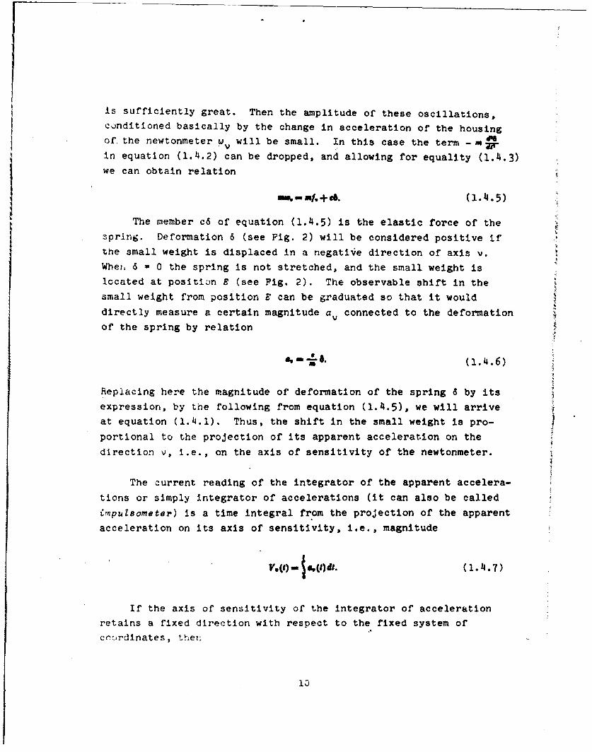
is sufficiently great. Then the amplitude of these oscillations,
conditioned basically by the change in acceleration of the housing
of, the newtonmeter w will be small. In this case the term - nx-in equation (1.4.2) can be dropped, and allowing for equality (1.4.3)we can obtain relation
nomm.+e (1.4.5)
The member c6 of equation (1.4.5) is the elastic force of the
spring. Deformation 6 (see Fig. 2) will be considered positive if
the small weight is displaced in a negative direction of axis v.
Whet, 6 = 0 the spring is not stretched, and the small weight is
located at position E (see Pig. 2). The observable shift in the
small weight from position E can be graduated so that it woulddirectly measure a certain magnitude a connected to the deformation
of the spring by relation
. -- .. (1.4.6)
Replacing here the magnitude of deformation of the spring 6 by its
expression, by the following from equation (1.4.5), we will arriveat equation (1.4.1). Thus, the shift in the small weight is pro-
portional to the projection of its apparent acceleration on the
direction v, i.e., on the axis of sensitivity of the newtonmeter.
The current reading of the integrator of the apparent accelera-
tions or simply integrator of accelerations (it can also be called
impulsometer) is a time integral from the projection of the apparent
acceleration on its axis of sensitivity, i.e., magnitude
V.(8)- . (t. (1.4.7)
If the axis of sensitivity of the integrator of accelerationretains a fixed direction with respect to the fixed system of
cncrdinates, thern
10

",'-r-.(1.11.8)
where v (t) -projection on the direction v of velocity of the hous-
ing of the integrator in the same fixed system. Therefore, sub-
stituting into equation (1.4.7) the expression for a from equation
(1.4.1) and using equality (1.4.8), we obtain the relation
VQ) - v,(Q)- w(o)- !()dt, (1.4.9)
which connects the projection of velocity v (t) with the reading of
the integrator of acceleration V (t). The latter is called in thisV
case the projection of the apparent velocity on direction v.
Function f (t) which stands under the sign of the integral in
the right side of relation (1.4.9) when the earth is not proposed to
be flat, is changed with the course of time because of a change in
the position of the missile relative to the earth.
With alternating crientation of the axis of sensitivity v, for
example, when the integrator of acceleration is located directly
aboard the missile, equations (1.4.8) and (1.4.9), of course, are
not applicable, and the reading of the integrator of acceleration is
no longer equivalent to the corresponding projection of the apparent
velocity.
5 5. Construction of a Ballistic Function by Means ofTwo Integrators of Accelerations and a Computer
In this section let us examine the use in the system of Inertial
control of the flight range of two integrators of accelerations.
Let us assumne that the integrators are stabilized so that the axis
of sensitivity of one of them during the whole power-flight section
of the missile would remain parallel to the horizontal x axis, and
the axis of sensitivity of the other would be directed parallel to
the vertical y axis.
I2

In the examined case, i.e., under the assumption of a nonrotat-
ing flat earth, projections of accelerations of the force of gravity
on the x and y axes are expressed by equations
Consequently, in accordance with formula (1.4.1), projections of the
apparent acceleration on the same axis are the quantities
'.-W(t). 4,-W,(t+g. (1.5.2)
where d M o*dQ) dpv () 5 3where -. (1.5.3)
are corresponding projections of the real acceleration of the missile
in the fixed system of coordinates xy. Here x(t) and y(t), just as
earlier, are current coordinates of the missile on the power-flight
section :f its flight.
The current readings of the integrators with axes of sensitivity
parallel to axes of coordinates x and y, according to equation
(1.4.7), are quantities
which are projections of the apparent veZocity of the missile,
respectively, on the axis of the fixed orientation x and y. In
virtue of equations (1.5.2) and (1.5.3) they are connected with
projections v (t) and v y(t) of the real velocity of the missile
relative to the system of coordinates xy by relation
V.)()- .Y). VY)- v,) + St. (1.5.5)
TIto the latter ccnstants of integration are absent, since projec-
torjs of the real velocity of the missile at the initial instant
12
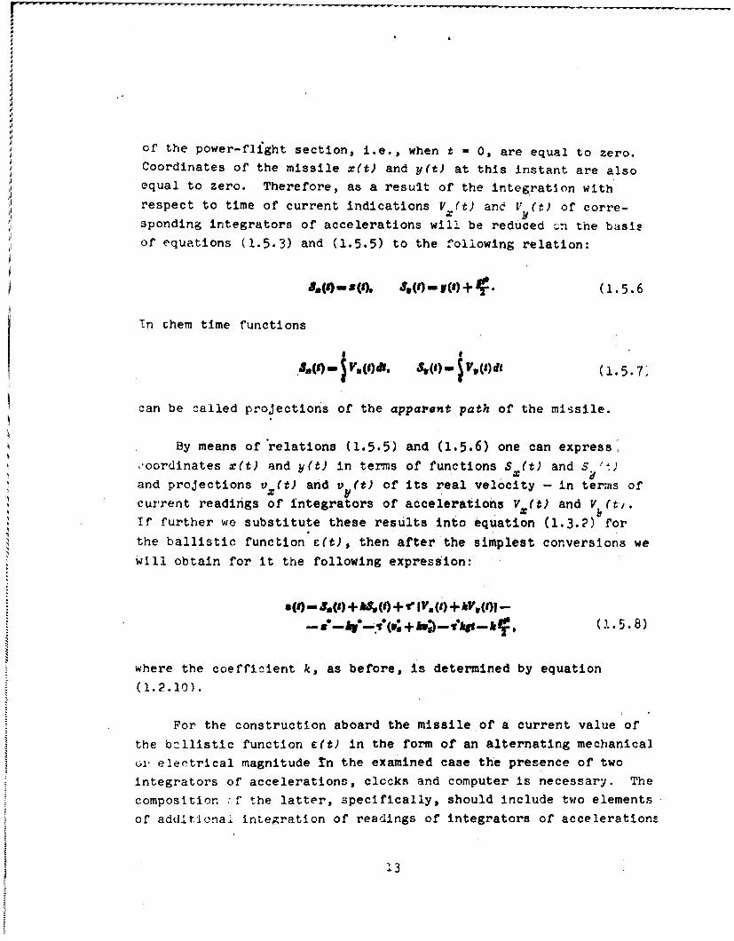
of the power-flight section, i.e., when t - 0, are equal to zero.Coordinates of the missile x(t) and y(t) at this instant are also
equal to zero. Therefore, as a result of the integration with
respect to time of current indications V (t) and V (t) of corre-xsponding integrators of accelerations will be reduced cn the basis
of equations (1.5.3) and (1.5.5) to the following relation:
5.((9z()(, S(S) - () + . (1.5.6
Tn chem time functions
.3(s)" In(#)d. 39(1) V .(1) A (l.- 5.7
can be called projections of the apparent path of the missile.
By means of relations (1.5.5) and (1.5.6) one can express,
•oordinates x(t) and y(t) in terms of functions S (t) and S3 't)
and projections v (t) and v (t) of its real velocity - in terms of
current readings of integrators of accelerations V (t) and V (t.
If further we substitute these results into equation (1.3.2)'for
the ballistic function c(t), then after the simplest conversions wewill obtain for it the following expression:
*( -(. () )+& (t) + v IV. (t)+ kVv(t)-
where the coefficient k, as before, is determined by equation(1.2.10).
For the construction aboard the missile of a current value of
the ballistic function c(t) in the form of an alternating mechanical
or- electrical magnitude Tn the examined case the presence of two
integrators of accelerations, clocks and computer is necessary. The
composition ,f the latter, specifically, should include two elements
of additional integration of readings of integrators of accelerations
13

§ 6. Control of Flight Range of the Missile by Meansof a Single Integrator of Accelerations with
Inclined Orientation of Its Axis
An attentive examination of expression (1.5.8) for the ballistic
fu..ction c(t) leads to the conclusion that sums
V.(0 + kV,(). . ( + Up, ((1.6.1)
entering into its composition can be formed aboard the missile by
means of vnly the integrator of accelerations with subsequent addi-
tional time integration of its instant readings. The axis of
sensitivity v cf such an integrator should be inclined during the
whole time of tihe power-flight section of flight of the missile to
the horizontal axis x at a constant angle a, the magnitude of which
is connected witn coefficient k by relation (1.2.11). Thus (see § 2
of this chapter), the direction of the axis of sensitivity of the
mentioned integrator is perpendicular to the vector of velocity of*re miss le it th< instLnt of reaching by it of the target C with
ca.culated motion (Fig. 1).
Let us note, first of all (Fig. 3), that for projections on
the direction v of the acceleration of the force of gravity and real
acceleration of the missile we have equations
i-ntna . , w.(t)cona + I(,Q)sia. (1.6.2)
Consequently, Recording to equation (1.4.1), we have
,. - w)--1(t)i - WQ)cos + w) +A si, a (1.6.3)
or, taking into account equality (1.5.2),
i.(8) - d6 (t) Moa + a, Mt sin a. (1 6
The last :elation indicates that the apparent acceleration is a
ve'or in:h.-e components are parallel to axes of coordinates x and y,
respectively equal to quantities a (t) and a (t).

A-
I
Fig. 3.
Integrating expression (1.6.4) for the projection of the
apparent acceleration on the direction v with respect to time, and
taking into account equations (1.4.7) and (1.5.4), we obtain equality
V.)- V,(9)wa +V,(t) zinc, (1.6.5)
which indicates that quantity V (t) is in this case a projection on
the direction v of a certain vector with components V Ct) and V (It
along axes x and y.
Function VV (t) is the current reading of the integrator of
acceleration whose axis of sensitivity has the direction v. Integrat-
ing this time function and taking into account equation (1.5.7), we
obtain a new relation
$ (t) -- $ (9) e . +o at ,w(t)sina , ( 1i. 6 . 6 )
in which quantity
)- V(t)dt (1.6.7)
0,on be called the projection of the vector of apparent path of the
missile on direction v.
Relations (1.6.5) and (3.6.6) can be given with the help of
equation (1.2.11) the following form:
15

V. (1) CM S V.(J) + k ,(tl-(1 6.and VVI (1.6.8)
( e a IS.(() + .V,, (s). (1.6.9)
From the obtained relations it follows that sums (1.6.1) and, con-
sequently, and expression (1.5.8) for the ballistic function e(t)
can be constructed aboard the missile by means of the use of current
readings of the single integrator of acceleration and of its time
integral. Really, on the basis of relations (1.6.8) and (1.6.9),
expression (1.5.8) is converted to the form
aS w- t S,(t) + v,(S)-(" +,")-
" (,* + -k-k -. (1.6.or)
As was already mentioned above, the duration of the power-flight
section is determined by equation c(t) - 0. In accordance with
equations (1.6.10) and (1.2.11), this equation, which will sub-
sequently be called ballistic, is reduced to the following, more
convenient form:
+ -S.(S) -r ,, o-, + (, +gS)s,. ci+
§ 7. Conversion of the Ballistic Equation by Usinga New Rectangular System of Coordinates
The ballistic equation (1.6.11) acquires a more transparent form,
if we introduce a new fixed system of coordinates En with the same
origin as that for the system xy. Axis of this system of coordi-
nates Is directed parallel to straight line v, i.e., at the same
angie a to the horizon (to the x axis) at which the axis of sensitivity
of the integrator of accelerations should be located (Fig. 4). Then
axis n will be the antiparallel to the vector of velocity of the
mi,.sile at the instant of its hitting of the target with calculated
motion (-ee Fig. 1).

El If
Fig. 4.
Coordinates of the end of the calculated power-flight section
of the trajectory of the missile in the new system or coordinates
are designated by r* and n*. They are connected with c-ordinates
xA and y* or the same points in the xy system by equations of con-
version
Let us designate projections of velocity of the missile on the axis
, and n with its calculated motion at the instant of the switching
off of the engine by v* and v*. They are connected with projections
of the same velocity on the axes x and y, with quantities v* and v*,
by similar equations
For moving coordinates of the missile in the system tn, which refers
to its rea2 motion, let us introduce designations E(t) and -(t', for
projections of its velocity on these axes - v (t) and v n(t), and,
finally, for projections of acceleration - w(t) and w n(t).
Since the axis * and direction v are para!:!l, then th.. nrc-
Jection of acceleration of the missile on the direction v is the
equati on
d() - (1.7.:)
17

and, consequently, according to equations (1.4.1) and (1.6.2), we
obtain
(1.7.4I)
At the initial instant (t = 0) of the power-flight section,
coordinates of the missile &(t) and r(t) and also projections of
its velocity v (t) and v (t) are equal to zero. Therefore, succes-sively integrating expression (1.7.4) for d2 (i)/dt2 with respect to
time, we obtain equations
I(5 - ( I.V 7.geuna)
where V (t) and S (t), as before, are projections of the apparent
velocity of the missile and its apparent path on direction v or,
which Is the same, on axis F. They are connected with the projec-
tion of the apparent acceleration 2V(r) by relations (1.4.7) and
(1.6.7).
When using equations (1.7.5), (1.7.2) and (1.7.1) the ballistic
equation (1.6.11) for determination of the instant of the switching
off of the engine is reduced to the following simple fo'm:
-r. (1.7.6)
Not entering into equation (1.7.6) is either the coordinate.of
the missile ri(t) or projection v (t) of its velocity on axis n. This
means that the small distinction in the mentioned magnitudes at the
enu of the power-flight section from their calculated values n* and
'Equation (1.7.6) can be obtained directly from the ballisticequation U(t) 0 0, in which function c(t) is taken in the initialfirn (1.3.2). In order to be convinced of this, it is enough to sub-stitute in expression (1.3.2) coefficient k by its value followingrrom the relation (1.2.11) and to use equations (1.7.1) and (1.7.2)and also those similar to them for quantities &(t) and v (t).

n correct to smallness of the second order should not affect theflight range of the missile. In essence this is explained by the
fact that for the control of the flight range of the missile it is
enough to use only the integrator of accelerations whose axis of
sensitivity is parallel to the axis t or, which is the same, as
direction v.
§ 8. Geometric Examination of the Condition ofHitting of the Missile on the
Assigned Target
From a geometric point of view the ballistic equation (1.7.6) of
the previous section can be given the following interpretation. Let
us assume that the motion of the missile is such (Fig. 5) that at
the instant of the switching off of the engine it proves to be at
point A', shifted with respect to points A - the end of the cal-
culated trajectory of the power-flight section on a small segmentparallel of axis n. If its velocity at this instant appears the
same as that at the end of the power-flight section cf the calculated
motion, then the trajectory of the missile in the free-flight section
will have the same form as that in the calculated case. In order to
obtain this trajectory, it is enough to shift by the magnitude ofsegment AA' the whole calculated trajectory forward in the directicn
of axis n or, which is the same, in the direction of the tangent to
the trajectory at point C of its intersection with axis x (see Fig. 5).
it is obvious that the point of intersection of the "shiftea" tra-jectory with the x axis will be remote from points C, i.e., from thecalculated points of fall of the rocket, on a smallness of the
second order.
Let us assume that, on the contrary, at the end of the power-flight section the rocket arrives accurately at the calculatcd point
:,, .t at a v locity somcwhat distinguizhcd fromn the cal:ulatcd in
magnitude and in direction (Fig. 6 and Fig. 7). The form of thd
traj,,.e.3 ' to be different, and I. genc.ral the rcvkct ""31
nQ lknger hit the assigned target.
19

A/A
Fig Fig
Fig.Fig 5.7..6
Nevertheless, as follows from the ballistic equation In the
form (1.7.6), if the velocity of the missile will be different from
the calculated by a small vector parallel or' axis n (Fig. 8), then
the deviation of the rockcet from the target will also be a magnitude
of the second order of smallness. Thus, in the case of a nonrotating
fl ,:: earth deprived of an atmosphere, it is possible to shnw su'ch
~rci~gdirection.; of zmall *;ct-or-z ol' the chango in velocit"Y or
t% zillft :' thz: ro:kcct at th,,c and of the pouecr-fl~.ght seection, in
thLu prc~rcncei which thL change .;n flight range ol' the rocket has
m, ~ ~ a ; - hrzoci ;der --f -- lnez SImar directions
car,1 be z3-.owr1 in general if one considers the rotation of the earth
AnG its rotisp'-trical state in the presence of an atmosphere. However,
Thev prc-ve to be ilfferer2L, and for the solution of the problem, on
20

Fi.g. 8.
selection of the proper instant oif the switching off of the engineof one integrator of accelerations with the axis of sensitivity ofconstant direction, in general, they are insufficient. The mentionedproblem (also correct to smallness of the second order) is mostsimply solved with the help of two integrators of accelerations (see§ 3 cf Chapter III) with additional irtegraLion of rcadlnCs c."
of them.
C
C
C
~ c

C H A P T E R II
THEORY OF INERTIAL CONTROL OF FLIGHT RANGE OFBALLISTIC MISSILES IN THE
GENERAL FORMULATION
§ 1. Expression of the Error in Flight Range of theMissile with Small Changes in Parameters of the.
End of the Power-Flight Section.Ballistic Function
The theory of inertial control becomes incomparably more com-
plex if with thre motion of the missile, in contrast to the simplify-
ing assumptionr accepted in Chapter I, we take account of the change
In acoelerati'2n of the force of gravity both in magnitude and in
JiLrectinn, c,.nsider the earth no longer to be fixed, and in the cal-
culalun of the free-flight section take account of the resistance
of the atmosphere. The basic difficulty consists here in the selec-
tion of a certain rather simple function of parameters measured
aboard the missile by inertial sensing elements. The function
should be such that with the achievement by it of the earlier
assigned value, it was possible to produce a switching off of the
engine, having provided the calculated range of the missile. An
example of a similar kind was given in Chapter I. This functi'on,
ca -l).urb>qurntly, Just as ir; ChcIpter I, balllistc (someti-'cz it
is called controlling and aiso controlZing functionaZ), is con-
structed aboard the missile by means of the computer, which uses
current readings of the integrators of accelerations. The magnitude
of the tallistic function should be directly connected with the error
in the flight range of the rocket which -would occur if the switching
off of thf engine occurred at the current instant of time. The
22
system of inertial control in turn sl:auld give a signal for cessation
of the operation of the engine upon achievement by the ballistic
function of a value which corresponds to the turning of the mentioned
error into zero.
One of the ballistic functions is the error itself in deter-
mining the flight range of the missile, expressed in terms of its
moving coordinates x(t), y(4), z(t) and projections v (t), VY (t),
v (t) of velocity relative to the so-called starting system of
coordinates xyz connected with the rotating earth. In this case it
is proposed, of course, that at precisely the instant t complete
switching off of the engine occurs.
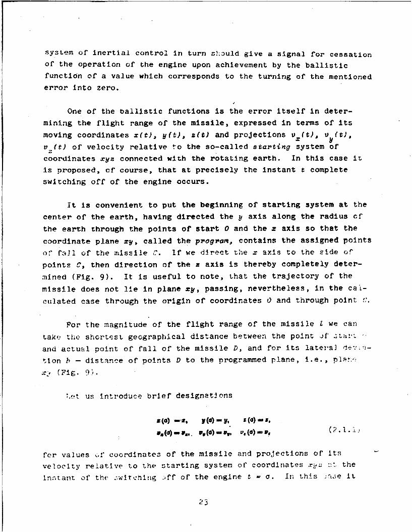
it is convenient to put the beginning of starting system at the
center of the earth, having directed the y axis along the radius of
the earth through the points of start 0 and the z axis so that the
coordinate plane zy, called the program, contains the assigned points
of fall of the missile C. if we direct the x axis to the side of
points C, then direction of the x axis is thereby completely deter-
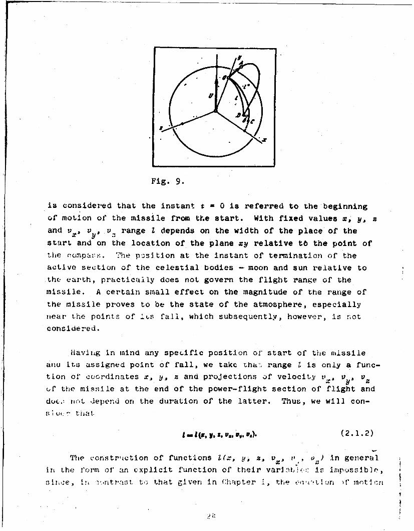
mined (Fig. 9). It is useful to note, that the trajectory of the
missile does not lie in plane zy, passing, nevertheless, in the cal-
culated case through the origin of coordinates 0 and through point ",.
For the magnitude of the flight range of the missile I we can
take the shortest geographical distance between the point f" lt: r
and actual point of fall of the missile D, and for its lateral detvii-
tion b - distance of points D to the programmed plane, i.e., pI~r.
, (Fig. 9'.
,,-t us introduce brief designations
SO@) -,go F(a)my, Z (a) mS,
vs (a) vs. y (a) - V. v. (a) - .
for values oif coordinates of the missile and proJections of its
velocity relative to the starting system of coordinates .r :. the
In:;tant of the :wircning _Jff of the engine t = a. It- this :atse it
23
2
Fig. 9.
is considered that the instant t - 0 is referred to the beginning
of motion of the missile from the start. With fixed values x, y,
and v, u , v, range I depends on the width of the place of the
start and on the location of the plane xy relative tO the point of
the eompa.-:. The p.sition at the instant of termination of theactive section of the celestial bodies - moon and sun relative to
the earth, practically does not govern the flight range of the
missile. A certain small effect on the magnitude of the range of
the missile proves to be the state of the atmosphere, especially
near the points of Ils fall, which subsequently, however, is not
considered.
Having in mind any specific position of start of the missileariu its assigned point of fall, we take Lha:. range Z is only a func-
tion of coordinates x, y, z and projections uf velocity v, V , Vzuf the missile at the end of the power-flight section of flight and
dw(.. ri-tC, depend on the duration of the latter. Thus, we will con-S.1 U,_ " that
l (9, VP St V ,, V ,, V ). ( 2 .1I. 2 )
The vonstrction of functions (x, y, z, , if, 0 ) in general
in the form of' an explicit function of their varla i(!:: is impossible,slro,:e, I!, ',.,ntrnst t,> that given in Chapter , the 0 &,1.. I.)n )f" m t 1t,rt
- , I

of the missile in the free-flight section in quadratures are not
integrated. Nevertheless, mathematical machines with great accuracy
allow comparatively rapidly calculating the magnitude of range of
the missile I according to data of its coordinates x, y, z and pro-
jections of velocity v, V VZ, which corresprnds to the end of the
power-flight 3ection in the starting system of' coordinates x~i.
Let us designate by x* y, z4 and v *, v*, v* those values of
2.--ordlnates and of projections of velocity of the missile in the
starting system of coordinates xyz, which orrasponds to the end of
r.he power-flight section in the calculated motion and by Z* the cal-
culated range of its flight. In accordance with equation (2.1.2).
we have
W.-- , S". 40, w,*, V ). (2.1.3).
Let us form expression
/ W--tl #. i . t, (2-1 4)., t. , l-
It can be accepted as the ballistic function mentioned in the
beginning of this section. Actually, if we turn off the engine at
any arbitrary instant t, then value of the selected function corre-
sponding to this instant is directly the error in the flight range
of the missile. If, however, the engine is turned off at that
instant t = a at which this function turns into zero, then, naturally,
there will not be an error in the flight range.
because of the absence of the equation which expresses function
L?. I.?) in an explicit form in terms of its arguments, the practical
use of the difference (2.1.4) as a ballistic function is difficult.
.onsiderably simpler is another ballistic function, which is obta.,-ea
from the expansion of function I into Taylor series about calculated
values of its arguments, i.e., about the totality of quantities x*,* ,~ v*, v, and V*. According tc expression (2.1.4), retaining
only smallness of the first order, we thve,

+, _ t-(,)-' Va N + I (0-o jr+ IV ()-N~ (2.1-5)
Here the partial derivatives 7., J71, -W. r. ,-. called balZli8tic
coefficients, are taken at values of their arguments, respectively
equal to x*, y, z v*, v* and v, and, consequently, for the
assigned flight of the rocket are constant quantities. The ballistic
.erflcients can be calculated, specifically, on high-speed computers.
It is obvious that with a small deviation in the motion of themissile from calculated as a balli3tic function one can take expres-
sion
08 a
,nctually, with the switching off of the engine at the instant when
this expression becomes equal to zero, the difference between the
real and calculated flight range of the missile proves to be amagnitude ;'J the second order of smallness. In this case deviations
in the parameters of the actual motion of the missile from the cal-culated rt the end of the power-flight section of its flight are
taken ae smallness of the first order.
§ 2. Equations Connecting Coordinates of the Missile
in Starting and Nonrotating System of Coordinates
ul.I., prub ~,~i'.f lnt.tial guldancc; the sta.ill sytem of'*urdinatcs represents certain inconveniences. Specifically, the
ietcrmination of coordinates and components of velocities of the
'If we do not take into account, of course other facts disturb-!rig the accuracy of flight of the missile, specifically, the effect
f Rtmonphric -onditions at the end of the power-flight section.
26

missile in this system according to readings of newtonmeters or
integrators of accelerations is complicated by the necessity of
calculation of translational and coriolis forces of inertia. Let
us introduce, therefore, the nonrotating system of coordinates En4
with the same beginning at the center of the earth as that for the
starting system xyz, which rotates together with the earth. Let us
assume that at the instant of the beginning of motion of the missile
t = 0 the axes of system of coordinates &nr and xyz respectively
coincide.
Let us designate by U&, V/n and U projections of angular
velocity of the earth on corresponding axes of the system of co-
ordinates Crh and by U , UY and Uz - on axes of the system xyz.
For an arbitrary instant of time the following equalities are
valid
U - U. - LU. U, - U1,M MU,Ut - us -- WU. ..
where Z, ,i, n - direction cosines of the earth'z axis and, con-
-et.ent~, vector V in the system of coordIr.-tlu ETl4 or, whiun -
trie: :;;ae, in the system of coordinates xy:;.
After the time t after the start of the missile, tne -vstei ct'
ciordinates xuz will be turned counterclockwise at angle
IPM U4
rvlative to the system n4, if we observe ,in,. or. the os>o c"
the positive direction of the vector of angular eioc4t:, the
e.th I (i.e., on the side of the sthr Polr.i .,.
Together with the current coordinates of the mis.ile x(t), y )
and z(t) in the starting system of coordinates xyz, let us introduce
its coordinates Ut), n(t), 4(t) in the system n4. Axes of the
latter, as follows from the aforementioned, do not change their
rier:tation rc-ative to directions at fixed stars.
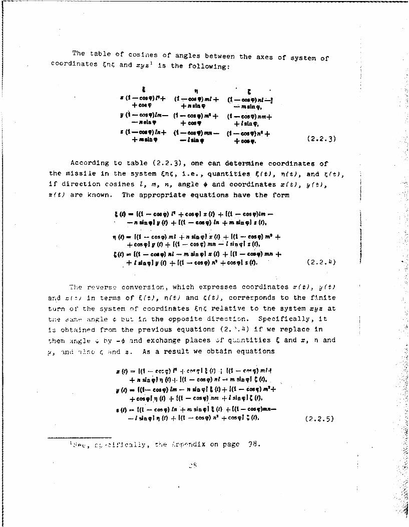
The table of cosines of angles between the axes of system of
coordinates &n and xyz' is the following:
z ( -Cos ) P+ (I--eosY)mt+ ( C-os g) R-+CosY +as.In -asla,
(1-cosy)rn- (1-cosy)m'+ (I-eos)nm+--ui + cOS9 + Isin g,
s(i- 9)In+ (I-Coa)m- (t-cosy)n'++mang -lu9W + oCg. (2.2.3)
According to table (2.2.3), one can determine coordinates of
the missile in the system &n4, i.e., quantities C(t), ,(t), and (t),if direction cosines 1, m, n, angle * and coordinates x(t), y(t),
zet) are known. The appropriate equations have the form
o- s +( -P X) + os + [0 - CoszM --- -in9l F (1) + [(0 - cosg) In + in sin 9 1 s (9),
() - [(- cosy) m1 + nsing X () + ( -eos) m' ++ Cos V(t) + [(i - Cosq) mn - 1 sin q1 z(9),
C(s - ((t - cogI) ,I - msin y! z(j) + [(I - coa.),n +
+ I sLin) (1) +( -cos) ' + cosQ (0. (2.2.41)
... reverse, conversion, which expresses coordinates y(t), (t,
and .(t) in terms of &(t), n(t) ana C(t), corresponds to the finite
turn of the system of coordinates & relative to the system xyz at
t a~'.- angle Z but in the opposite direction. Specifically, itis obtained from the previous equations (2..4) if we replace in
them rFgle € by -€ and exchange places of" quLntities and x, n and
y, and alse ¢ nd z. As a result we obtain equations
z (t) - 1(1 ---e z: ) P" -.j . , I () -; [( -- c ) m i-I
+fnsing1i c()-I- (i -- cos).l- msinvl C.(),I(a) ((- CoST) In - n sin gl E (t)+ C( - cos) m'++cosJ.n (M + ( - cosT) nm + ! slsh i(1Y,
s (I) - 1(I - osp) In + msinqy] () + [(!-cos)mn-
-invil,() +I(t -cosg)n' +COSl(), (2.2.5)
~ s~-:ifca~,, e.'r-ndix on page 98.

which, of course, can be obtained directly, using table (2.2.3).
§ 3. Projections of the Velocity of the MissileRelative to the Nonrotating
System of Coordinates
Earlier there were introduced designations v (t), v (t) andx
(t) for current values of projections on axes x, R and z of veloc-
ity of the missile relative to the starting system of coordinates
xyz rotating together with the earth. Projections of velocity of
the missile in nonrotating system of coordinates &nC on the axis of
this system are designated, respectively, by uC(t), zn(t) and u (t).
It is obvious that
in the same way as
Quantities vX(t), v (t) and vt(t) can be expressed by u (t), un(t),
u (t) and inversely. According to equations of kinematics relative
to the motion of the points, we have
us (S) - V. (1) + uX (9)- U a).a M - ,(5 + Ur (M)- u().5,.t - .M + U M- VW (t). (2.3.3) Th
t hwhere u,(t), U Y(t), u (t) -projections on the axes x, & and z of
the velocity of the missile in the rotating system of coordinates
In equations (2.3.3), In accordance with equalities (2.2.1),
let us replace Ux, U and U., and coordinates x(t), y(t) and z(t)
will be expressed by means of relations (2.2.5) in terms of co-
ordinates &(W), n(t) and 4(t). If.further projections u (t)', i(t)
29
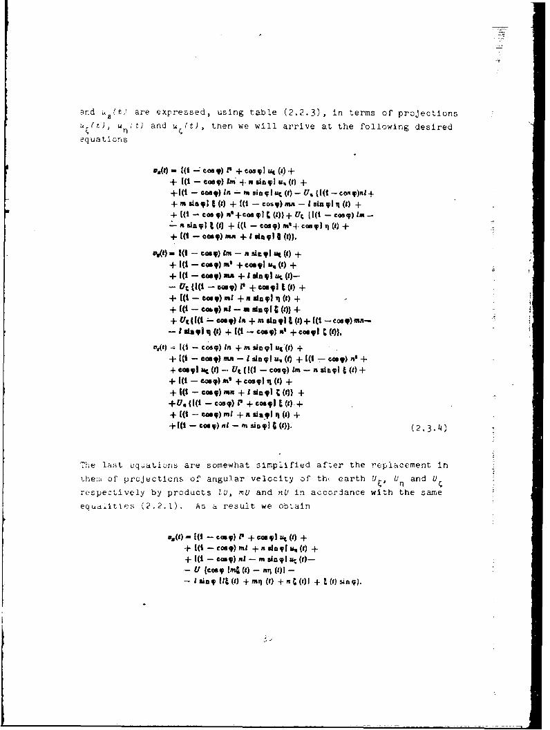
and Ct) are expressed, using table (2.2.3), in terms of projections
U (t), u t,) and u. (t), then we will arrive at the following desired
equations
V. [(1 -cos q) P' + Cos q 1 () +
+ 1( -C oST) IM, + pg "al , (1) ++((t - Cos V) In - ft sing I ut (I) - U,, (1(t -cosq)nI++ m in (9) + 41 - cosq)mn -I sin qIiq (9) ++ 1(t - ea8y) '-+coy ITC (9))+ U (1(1 - CoST) IM -
a in , (1 + 1-coo 9) W4- cs9lu i (,) ++ I(t -Gras) MR + I -iO I().
wil) 1(1 - CoS) Im - n si,.V Ut (9) +
+ I(I - cOST)M + osal U,.(9) ++ I(t - GOOT) mA + I sin l u (9)-- U(I -cor) T) +cm,, + (G ) +
+ I( C q) t - a 1 +(t)}++ U. 11(t - corny) lot + n limIl (9)+ 1( - cooq)n n-
-S ita (8) + ((t - coo.q) no + co q1 }
.S( - cosq) In + m sinyl ut'(9) +
+ [(1 -c quy) mn - I sl qIu () + 1(t - coony) i' ++ c41g. ac (t) - Ut (((I - co) In - n singl t (t) +
+ I(-co?) m' + oS) 'Q (9) ++ 1(1 - corny) um + I sly 1 n (V)) ++ U. {(0 - Cos) 40P + Cos~ 9, ()+
+ [(t -. ,) mI + a si,,V1 q (1) ++1(1 -coas) nL - m sino (t)). (2.3.4)
The last cquaticons are somewhat simplified after the replacement in
the,;i of projections of angular velocity of th( earth U, U and U
respectively by products 1U, U and nU in accordance with the same
equailtics (2.2.1). As a result we obtain
u.()-4 -os q) 0 + C"1 "t (1) ++ [(I -coo q) m + n singIus (1) ++ 1(t - cor y) nt - m uinTl ur (f)-- U (Corn Im (9) - nq (9)1 -- Isinq IIt (1) +mq (r) +n (t)] + ()sin i).

N(1)= i - cosy) Im - n sinqT ut (t) +
+( -coo IF) m' + Coe j UO(W ++ f( coo q) mni + I sin ql ur. (9)--- (c{os 4 Int (t) - I C (t)1 - m ia 4 [t P) + ,,iq (1) +
+ n (1 +q(O sin ).u,(t)= (-coo)ln +m sin lu (f) +
+[( -Coso) mn - Isin u, () ++ t(-oo) to -+ cog UC (0 -- U (Coe8 y11 (9) - mt (01 -- • i-g [it (*) +mq () + n4 0 ( +o (2.3.5 )
it is obvious that by similar means it is possible to arrive at
equations which vxpress quantities u,, U and it in Lerms of v,
v _.nd z) We nave
Y z
4 m( - Cosy) 0 +Cos ,I ( +
+ [(-cag) In -as-nin g P, (t) ++ [( - cosyg) In + mn si 1 v. () ++ U (cosy [mz (I) - y (t)1 + 1I slna [Lz() ++ mv (t) + nz(,- x (t) in tp},
U.(t)= (I - cosy) ml + n sin l 'v (1) ++ 1(0- cos)m' +co's , (VV() ++ 1(1 - coo g)rn- I sin g v, () + U (cos.4-nz () -- is ()1 + m sing flx (9) + my (t) + nz (ty - (4in9 ),
()= i( - cos9) nI - m sap1 v. (t) ++ I(1 - cosy) nm +'I sin q v ( ) ++ c( o - cos)+n' + os4pv . () ++ U Icosye fly () - mz () ++Ain av 1lz () + my W + Az i- z ( sin. (,.
Error in Flight Jeange of the AlisilJo ":junction of Changes in Par:ieters of thc' ,':',
cf' t h- F'!wred- 1"V .ht Se I .... in tie-N--o(CItitqg o-yte o-- Loorizea&es.
Initial Ballistic Function
We wi.] designate coordinates and projections of velocities of
th"o nX. ,,le in the nor;rotating system of coordinates rj at the
iri:' - r:. of tlhc eni of tne tower,. d-f]light section of itz flight
'. : .-t .v,.Lv., ,.:; l ,tters r , , na u,, u m : .,
JZ

are similar to designations (2.1.1) introduced earlier for quantities
X, Y, z and v X vY, Vu, which refer to the starting system xyz. Thus,
(Z) L n ,(a) - o C (a) ,- L,
1 (o)m- ul.,(@) -v,. ", ur,~. (2.4.1)
Setting in equations (2.2.5) and (2.3.4) U - ha, we obtain expres-
sions of quantitles x, y, a in terms of F, n, ; and a and also
quantities vx. v , iV in terms of u,, nP uC, y n, and a. This
allows considering magnitude of range I as a function of values of
coordinates of the missile U(t), n(t) and 4(t) at the instant t = o.
projections of its velocity u (t), u, t) and u.(t) in the nonrotational
system of coordinates tn (at this instant of time) and, finally, the
duration itse1* of the powered-flight section a. In accordance with
formula (2.1.2) we now have
- (z.to yo,, ,,w. V,) M ( t , f,uu: ,). (2. 4.2)
it ir eaz:v to explain why in this case the range I clearly depends on
variabic o. Actually, the position of the rocket relative to the
earth at the same values of its coordinates in the nonrotating system
nC suostrzntially depenas on the position of the latter with respectto stariin, system of oord!oates xz connected to th4 earth, i.e.,
o, angle €t : ''. Thc .,me refers to magnitudes of" projections of
the e: tcr -f ve,.ty of the missile in the etarting system at the
t :in of termnaticn sf the powered-f.igh. section.
Calculated values of parameters of the end of the powered-
:'fllrh' ctlon 1n the starting system of coordinates x*, ,, z*,
0, v, arid v. correspond to calculation values of parametev b *
n*, u!, u*, a in the nonrotating system En . They are
connected with each other by equations (2.2.5) and (2.3.4) or (2.2.4)
and (2.3.6 , in which it follows to assume s - Uc*, considering 0*
as the designation of the calculated duration of the powered-flight
scuIr ;'f flight of tne missile. It is ,;bvious that in czordance-'ii r ur. a . . ,

C'- 5 (X.. z. V1 V.0) - I(', ,% o. U;. U, ;) (2. 4-.3)
where j*, as previously, is the rated value of the range.
The difference Al between the magnitude of the actual range of
the missile i and its calculated value V4 can be represented, similar
to equation (2.1.5), in the form of the expansion
AL - (I - F) -+ ( - q1) A+ (C - ) + (at - a;) +
ee
+CU)+H.U (2.4.401
where terms of the second and higher order relative to differen2es
are dropped
In contrast to the expansion (2.1.5), entering into equatlon
(2.4.4) is a term of the first order, which contains by a factor
the difference a - 6* between the actual time of the powered-flight
section of flight of the missile a and its calculated value of. The
same difference is contained by a number of terms of expansion
(2.4.4) of a higher order. The reason for this fact was already
explained in the beginning of this section.
Derivatives ._. , . a are themselves functions
of variables t, n, 4, u, Un, U and a. In the expansion of (2.14.4)
they should be taken at calculated values of enumerated variables
, ~,. {* u,. u*, zy oi, and, consequently, for the specific
assigned flight of the missile arv constant qu-.itiit. - ballistl
coefficient, which refer to the nonrotating system of coordinatos.
Let us show that they are all expressed in terms of ballistic
coefficients of the starting system , i' " ', # and
Actually, according to rules of differentiation of complex functions,
specifically, we have:
33

- +-~at at at of or 1O t8s, O , 1h
X+ (2.4.5)
Analogous expressions take place for derivatives , -, . ,Dl
and for the partial derivative . equation
at Oat arat l . 1 'a ,'_ , 40'1 &V aD,-. . *,g + + . (2.4.6)
is valid. Entering into enumerated expressions, the partial deriva-
tLves cf variables x, y, z, v V s with respect to variables E,
r, 4, VC V , V and a are formed by means of the application ofappropriate operations of differential equations of the type (2.2.5)
and (2.3.5), in which it follows preliminarily to set t a and
Thus, for instance,
-W -- (t -P) sin .s+(, i . s
U UI- (t - 1) USIn Us+ (Lu. sin VC,+n Cos.Us) N +
+ (In sin U - moos Us) up! + V'I ('u4 - ,)sin Us +
+ I M+ Mri+ nOens U's- tCosUZI,.
if now in equation5 (2.4.5), (2.4.6), (2.11.7) and ones similar
to them, we assume the values of all variables equal to the cal-
culated values, then thus the desired coefficients in expression
(L.4.4) will be completely determined.

V - will assume that as a result -f the sma'l deviation in the
reI m1 ntion of the missile from the calculated in the expansion -A,(2. .A), the terms caused by the so-called lateral deviation in the
Z e Man d -- u;4 are small in comparison with other
."rMs. '\t a -eslt the difference between the actual i*nd cAIcU! :ted
:':ght ringce of the missile Al can be represented by the appr.xinate
-V) + (,q " ql)+
51 81 81 81 81'.ht re ,- 0- , 0- and , as was already shown above, are number:)
are completely defined by the selected calculated !notion cf
.:xprez:.:ion ( .1i.b) ,orresponds _to the followi i L±i:.
• zr, :i. r, which we call the initial ballistic J'unction:
a(t) M l(g)-ol -- +I l8(- A+ I U.( M ;I
.-. .,.uj.. +-. . .-
.r', ~ *.t , U " , t ) and a (t) , as refore, are mcvi:.g ,-rainat:l:
In w>roject !, no )f velocity of the missile In the norir,'t:itinL sw -,,
f -.ngirze of the ml:;sile is turned off --t a. .:. t" ' ,. ** . t:, t, , - . A,' Vq , '-. . .. (2 . 1 1.] a nd (2 .14 .8 ) t L. w:: , _ , "
t:. I ii.,t:Ltc fc.In(.4. 9) correspondjing to thlt3 irst'tnt1 cuv'rvcL
-t' tne second order determines the error in tie fiight
"tn.ge I" t"le :IsciPe. To avold thls error, ont. ,nould turnr of' ,
,he mis-sile at the -stant when the Lca.listL' functicr-* ' u'n.; L' " ...... hus, trie ne ,essary instant ,_' %he swit,:,i,..
e by % -,. ,o , " -T-, ttor

k~) r~+ fTIMjQ)-iJ. .+ (u()- ul j +Y 0. (2.4.10)
Equation (2.4.10) will be called the initial balli8tic equation.
The basic content of subsequent sections of this chapter and
also Chiaoters III and IV consists in the construction of a series
rf other ballistic functions, with the help of which it is possible
as simply as possible to solve the problem about the inertial control
of" the flight range of the ballistic missiles. They all are obtained
by means of certain conversions from function (2.4.9) and different
presentations of coordinates and projections of velocity of the
mlislie in the nonrotating system nC in terms of current readings
of integratoro of accelerations.
5. Differential Equations Which Determine CurrentCocriinates of Motion of the Missile
The m nst natural, but, as it appears, not the simplest, method
:f c -nstruction of the left side of the initial ballistic eauation
(2.4.I0) aboard the missile is the preliminary obtaining of most
noving j.:'dlnates F,(t) and q(t) by means of solution of zne dif-
:'crentl eouati)ns. wnich connect these coordinates with current
a-ndln, .,f wo newtonmeters. The axes of sensitivity of the latter
s ncuI I -- ntain the fixed directions, respertively, parallel to axes
. .a.. the rionrotating system of coordir ;es & Readings of
the :entioned newtonmeters are projections a. t) and a (t) of the
Lparerll acceleratlon of the missile on the axis and n. According
tr e 2tifn (1.4.i) of Chapter I, in this case we have
at (9) - WO) - A. a(ll.) -uf WqM A (2.5.-1)
W (25.2)
: r- p.;.ecti~no on axes and n of the real a:celeration of the
:'. .t~ive t the f'lxed system cf coordinates Mn(, and

A- A !|($). ,(4). CCV); 1.(2.5. )I It 0|(). 11 (t). C (1k, 11
are, respectively, projections of acceleration of the force of the
earth's gravity, which depend in evident form not only on coordinat
of the missile, but also on time t. For an explanation of the last
fact let us note that even at the point with constant coordinates
relative to the nonrotating system &n; the acceleration of the forc
of gravity is changed with the course of time. Actually, with
respect to the system of coordinates &n4 the position of the earth
is continuously changed. At the same time the field of gravity of
the earth does not have radial symmetry, specifically, as a result
of the deviation in its form from a sphere. If the last fact is
disregarded and the earth is considered a sphere with radial and
symmetric distribution of density, then projections of acceleration
of the force of the earth's gravity will be represented by equations
Am~IRd 1. -low3I~~ (2.5.4)
no longer dependent in evident form on time. Into them f0 is the
value of acceleration of the force of gravity on the earth's surface
examined as a sphere of radius R, and
is the distance between the missile and center of the earth. Because
of the smallness of the lateral deviation in the rocket V(t' In com-
parison with the radius of the earth R, this coordinate in equation
(2.5.5) can be cropped. Correspondingly, it is possible to drop
coordinate r (t) in equations (2.5.3), considering the effect of this
coordinate on the magnitude of acceleration of the force of gravity
unimportant. Then relations (2.5.1) can be considered as a combina-
tion of two differential equations
(2.5.6)
37

for the search of desired functions k(t) and n(t) on the given
current readings aE(t) and an(t) of two newtonmeters.
The direct Lolution of the system of nonlinear differential
equations (2.5.6) aboard the missile for the purpose of seeking the
current values of coordinates F(t) and r(t) it is possible by means
of the use of a rather high-speed computer. In the subsequent two
chapters the approximation solution to these equations, which in
principle can be used in the system of control of the flight range
of the ballistic missile in the presence of onboard of its newton-
meters or integrators of accelerations and simplest computers is
used.
§ 6. Auxiliary Relation Connecting Magnitudes of
Ballistic Coefficients in the NonrotatingSystem of Coordinates
At different conversions of the initial ballistic equation
(2.11.10) one relation proves to be useful, and it connects magnitudesat 0 1 at at
of the ballistic coefficients and w in the nonrotating
system of coordinates En with projections of velocity u*, u* and
with projections of acceleration of the force of gravity f&(E*, n*;
J*), f (&*, n*; o*), which refer to the instant t = of of the termina-
tion of the powered-flight section of the calculated motion of the
missile.
Let us introduce functions E(t) and n*(t), which are current
coordinates of the missile in its calculated iotion on the powered-
flight section. They satisfy the totality of differential equations
(2.5.6), if in them the current values of projections a (t) and a (t)
of t11( app ,vrt accclration arte replaced by their calculated values
a*(t) and a*(t). Thus,
if - ,( 2 . 6 . 1 )
It a (') + fIt'(0, n*'0; 11.
38

Correspondingly, let us introduce functions **(t) and ri**(t), which
are coordinates of the missile in the free-flight section of its
calculated motion. Let us assume that in the beginning of motion
of the missile in the free-flight section the resistance of the
atmosphere is unimportant, and, consequently, the apparent accelera-
tion is absent. In this case one should consider that functions*A(t) and n**(t) satisfy the totality of differential equations,
which is obtained from (2.6.1) if in equations of the latter we drop
quantities a*(t) and a*(t) and replace variables &*(t) and nr(t)
respectively by C**(t) and nr*(t). We obtain
d-f-orm"(. 4-(S); nl.
(2.6.2)-7- to It' " ) ..
Let us designate the current values of projections on the axes 1 andn of the velocity of the missile in the powered-flight section with
its calculated motion by u*(t) and 0(t), and by u**(t) and u**(t) -
the corresponding quantities which refer to the free-flight section.
We have the evident equalities
_.f-e, ,(t,. k (2.6.3)
and, similar to them
The powered-flight section of the calculated motion of the missile at
the instant t = a* will pass over into the free-flight section, whence
it follows that
r on - r (do) - r. q" W) - I- 01' - fr. ( 2.65 )
and also
' - '- .3 4. (2.6.6)
39

According to equations (2.6.1) and equations (2.6.5) for the end of
the calculated powered-flight section,' we obta.in
-5--- 4; (*') + A W . ''(2.6.7)
.- ') + 4 W, ('; 4).
Similar relations can be ootained on the basis of equations
(.6.2) and the same equations (2.6.5) for the beginning of the
calculated free-flight section. They have the following form:
it wj!m(.v ; a), Wijo) (2.6.8)I i
Let us examine now on the calculated free-flight section of
flight of the missile the certain instant t - tP which followsfnd after the instant of the switching off of the engine t = o*. Correct
th tc sr.9Lalness of the second order we have expansions in Taylor series
fcr coordinates of the missile El and n., which refer to this instant,on. namely:
-6 r-# 03 t" (61 + (11-")(2.6.9)
- 0,) (a' + (t-,
or, taking account equalities (2.6.4), (2.6.5) and (2.6.6),
"+ (is--l U;, TI- Tr +(VI,- al U.. (2.6.10)
e atenat Similarly for projections u2 and u of the calculated velocity ofh]ence Si il rl
the missile aW Lhc merntiouied instant t = t we have
'In designations of the type d&(o)/dt it follows, of course, toconsider, that from the beginning an operation of differentiation ofth. a;.proprlat.- function is produced, and then the va' ue shown Inparenthesis c givcer to the argument.
rI

P110 G*) (1(2. 6.11)
+d
*q " "l (t1) "- m" 6') + (t1- o')dU
On the basis of equations (2.6.4), it is possible here to produce
the following replacement:
(2.6.12)
Taking into account, furthermore, equality (2.6.6), and also rela-
tions (2.6.8), we obtain n
t
Nj +(t~i J&(V ir;d*L(2.6.13)8 ; + (81 -9. 11 W .W; €)
Let us imagine such a motion of the nissile in .hc powered-
flight section different from the calculated, as a result of whic.
at the instant t - t it proves to be at the point with coordinateF
(i and nI, possessing a velocity the projections of which on axes
&land n are respectively equal to quantities u and u If at this
instant t - t the engine of the missile is turned off, then the
following free-flight section of its motion, because of the unique-
ness of solutic-1 to the problem of dynamics completely coincides wh
with the calculated. Actually, both motions are such that at the th
same Instant t - tI in them positions and velocities of the missile co
relative to the system of coordinates &nC coincide. Furthermore,
when t > t1 they are subordinated to the same totality of differential
equations, which refers to the free-flight section of its motion.
Thus, at such a powered-flight section the rocket will not nave an
error in the range of its flight. Consequently, parameters of the1 1
end of the powered-flight section of its motion El' n, 'd an u I
should satisfy the initial ballistic equation (2.4.10), i.e.,or:
+ '- 1 +
41

Replacing here quantities 1 and n, by their expressions according
to equations (2.6.10), and u and uI1 in accordance with equations
(2.6.13), we obtain after, reduction to the common factor t 0
equality
+a W. .,. +
+/1(' '; al + -0, (2.6.15)
which connects the ballistic coefficients W-g SK and in the
nonrotating system of coordinates &nr with projections of accelera-
tion of the force of gravity /&(t, v1;, a)',/, (t, '; a*) and with projec-
tions of velocity of the missile u* and u4 at the calculated Instant( n
;f the switching off of the engine. -
Let us exclude from equality (2.6.15) projections of accelera-
tion of :he force of gravity by means of relations (2.6.7) and use
t.ons (2.6.3). As a result let us obtain the new equality
W + +o,(2.6.16)
which will be used in the following section during the conversion of
the expression of the initial ballistic equation (2.4.10) tc the form
convenient for applications.
§ 7. Isochronal Variations of Coordinates andProjections of the Velocity of the Missile.
Basic Ballistic Equation
With the Juxtaposition of the real and calculated motions of
the missiles, let us call the isochronaZ variation8 of its co-
ordinates the differences
ft()- E()- r(. an (- q()-t'(1). (2.7.1)
42
i-

Similarly, let us introduce isochronal variations of projections of
velocity of the missile
(t)- U(Q)-nt(t), O()- u(f)--(Q) (2.7.2)
and projections of the apparent acceleration
aft- a(t)- a(), 01- a,(q-a(). (2.7.3)
We will consider the enumerated isochronal variations small quantities,
the squares and products of which can be neglected. Thereby, it is
proposed that the problem of thrust of the engine both in direction
and in magnitude is produced to a sufficient degree accurately.
Functions E*(t), n*(t), u*(t), u*(t), a*(t) and a*(t) refer to
the powered-flight section of the calculated motion of the missile
and, consequently, are determined at values of the argument t not
exceeding the duration of this section a*. At the same time in
equations (2.7.1), (2.7.2) and (2.7.3) functions (t), n(t), u(t),
u (t), a (t) and a n(t) refer to the powered-flight section of the
real motion of the missile, the duration a of which can be both less
and more than the calculated value a*. Therefore, for the complete
certainty of variations 6&(t), 6n(t), 6u&(t), 6un(t), 6a&(t) and
6a (t) in the whole time interval of the powered-flight section of
the real motion of the missile, one should agree upon what is under-
stood by functions &*(t), n*(t), u*(t), u*(t), a*(t), a*(t) with
argument t somewhat exceeding quantity a* (within 'lmits of the
allowed variance of duration of the powercd-flight section for the
specific type of missile). If one assumes that the thrust cf the
eiglie with termzlatlon of the powered-flight section is locwcredi
grai-.'.Il or by stages, then for thec functicn. .. :hn t > a* It i 7
natural to take, respectively, functions &**(t), nf*(t), uU(t) and
*(t), which refer' to the calculated free-flight section and assume
functions a*(t) and a*(t) equal to zero. In this case it follows to
expect that the isochronal variations (2.7.1), (2.7.2) and (2.7.3)
will be small at the short time interval directly following the
calculated Instant. or the switching off of the engine.
43

For missiles with the sudden switching off of the engine, on
the contrary, it is more preferable to consider functions V(t),
n*(t), u*(t) and u*(t) when t > o* equal to their calculated values
calculated on the assumption that the- engine of the missile at the
instant t = a* was not switched off. Here the isochronal variations
(2.7.1), (2.7.2) and (2.7.3) again can be considered small.
Let us use now equations (2.7.1) and (2.7.2) for isochronal
variations of coordinates and projections of the velocity in order
to transform the initial ballistic equation (2.4.10) by which, as
was already mentioned, the necessary time of cessation of operation
of the engine of the missile for its hitting of the assigned targetis de-termined.
Let us present in the beginning equatior (2.4.10) in the
following manner:
+M V JN 1q -1 ) at) -[r (t) -,) 8+ 11%.-, M -a (0 ;,),; +
+ +f-)-;, + -al (2.7.4)
Irto, the lep't side of the last equation let us substitute expressions
for Isochronal variations of coordinates and projections of the
vciocity of the rocket, according to equations (2.6.5), (2.7.1) and(.).... In its right cide lct u. ex-pand each of the funct.on "*(t),
rj4'*,', "~(t), zu(.) in Taoylor -ti.es near the value t uO, retain-
i ; ~.thc c,_,3on on]y tcr. of th fir.. order of sWallness. Wc
obtain
at1at ()4 () wc-+ q M) + Mu ( + am (t)u
all du t da 8U J3
+ '*(*') 81 +d'*(s') at at (2.7-5)
414

I
The right side of the last equation can be considerably
simplified if we take into account equality (2.6.16) of the
previous section. As a result we arrive at the following equa-
tion:
rn~(~t) (e~) .-(e) ~.(2.7.6)
which, subsequently, we will call the baeic baiZtisc equation.
For the actual use of equation (2.7.6) in the system of inernial
control of the flight range of ballistic missiles its left side should
be constructed aboard the missile at current readings of newtonmeters
in the form of a certain electrical or mechanical magnitude.
b.
enno
thl
an
ar
th
di
of
ea
obt

CHAPTER Ill
APPROXIMATE PRESENTATIONS OF THE BAI.LISTIC EQUATIONDETERMINING THE INSTANT OF SWiTCHING
OFF OF THE ENGINE
§ 1. Differential E uations for lsochronalVariations of Coordinates of the'Missile in the Powered-Flight
Section of Its Motion d
In the previous chapter there was obtained the so-called basic
b .,listic equ:7ti n (2.7.6), which should satisfy parameters of the
end of the powered-flight section in order that the rocket would
not have an error in the range of its flight. For the construction
,.f the left side of this equation, it is necessary to know aboard
the missile the isochronal varia.ions of coordinates 6t(t) and 6n(t),
and also projections of the velocity 6u(t) and 6u (t). The latter
are, of course, time derivatives of variations of coordinates, i.e.,
The coordinates themselves V(t) and n(t) .f the real motion of
the missile in the powered-flight section satisfy the totality of
d!fLcr(_irlial equatlu,, (',.5.6), and coordinates of the calculated
motior: - totality (2.6.1). Let us form the differences, respectively
of the left and right sides of these equations and equate them to
each other. 'Taking into account equalities (2.7.1) and (2.7.3), we
obtair,
,.6

'"q M (9) +/ I" (0 6t a(9). q"'(f) + q (t); 91 -
-. (3.1.2)
In the right sides of the last equalities we can use the
expansion in the Taylor series of the function according to increases
in two of its a.rguments. Retaining only terms of expansion of the
first order relative to variations 5S(t) and Wt) and carrying out
simplifications, we will arrive at the following totality of two
linear differential equations:
(9) + att M + W/ a (9).JF'-()+ ) (3.1.3)
s*- ,(1) + !' at(.)+ a ()
The desired functions of these equations are isochronal varia-
tions of coordinates of the rocket 6t(t) and 6n(t). Initial condi-
tions for them can be obtained from the fact that at the instant of
the launch, i.e., when t - 0, coordinates and velocities of the
missile are the same both in real and in calculated motions. Con-
sequently, according to equations (2.7.1) and (2.7.2), we have
at(0), O, aq (O) = 0 (3.1.4)
and further
.o)-"(°)- ,9 - °" (3.1.5)
The right sides of equations (3.1.3) contain variables -
isochronal variations of projections of the apparent acceleration
of the rocket 6a (t) and Sa 1(t). In accordance with equations
(2.7.3), in principle they can be obtained aboard the missile by
means of a continuous formation of the difference between the real
rcading of the appropriate newtonmcter and its current calculated
1"7

Coefficlents of equations (3.1.3)1
' - --W W -' -W (3.1.6)
should be considered as time functions, known earlier for each
specific case of flight of the missile. In order to obtain these
coefficients, in accordance with rules of expansion in Taylor series,
in partial derivatives of functions IA(t,'; t) and A(Lq;f) according toSvarLables & and n, it is necessary to produce replacement of the
latter by functions *(t) and n*(t). Functions t*(t) and ri(t) are
earlier known according to calculated motions of the missile in the
powered-flight section. Thus, if aboard the missile continuous
(without substantial lag) integration of equations (3.1.3) is carried
out and thus magnitudes of functions 6E(t), 6n(t), 6u&(t) and 6u n(t)
become known, then the left side of the basic ballistic equation
(2.7.6) can be constructed by means of multiplying and adding devices.
Similarly, with the use of a clock mechanism the right side of this
equation 4-s constructed.
§ 2. Approximate Expressions for IsochronalVariations of Coordinates and Projections
of Velocity of the Missile.Simplification of theBallistic Equation
The simplest method of the use of integrators of accelerations
in the system of control of the flight range of ballistic missiles
is based on the simplification of differential equations (3.1.3).
in them terms containing as factors the isochronal variations them-
selves of coordinates 6&(t) and 6n(t) are dropped. This is equivalent
to the assumption about the fact that the effect on the missile of
f, rcv of gravity with its actual and calculated motions can be
.onsidered practically equal. Such an assumption is admissible only
'The equality in (3.1.6) follows from the fact that projectionsci' acceleration of the force of gravity are partial derivatives oftne potential of gravity according to appropriate coordinates.

with sufficiently small deviations In the real motion of the missile
from the calculated, i.e., at increased requirements for the accuracy
of ction cf the missile according to the assigned program. Equations
(3..3) are replaced in this case by the approximate equalities
-g-w (, A.()u- &21,- (3.2.1) Here
path
whence allowing for relations (3.1.1), (1.5.4) and (3.1.5), there are
equations for variations of projections of the velocity of the missile
where
6 a(9) - &C. (S). _t - ().(3 2 )am* (t) - S' s " i, (t) dt = 6V, (t).
- ~J~ .~,a 1 t~d=6V.1).are p
Quantities 6v (t) and 6k'V(t), which enter into these equations,
can ,e calleu isochronal variations o- the apparent velocity cf the
missile. According to equations (2.7.3), they are differences their
[ 8va(m) - mt--K[(s). 3v (t)- V (t)- -'(), (3 2 3)
tivelin which equat
U I
v 1(t) - 1 V t, V,(I)- a, (,)di (3.2.4) of th
are projections of the apparent velocity of the missile during its
actual motion and
V;( )- V'( . t ) ( ) d (3.2. )and a
are calculated values of the same magnitudes. and
Integrating in turn expressions (3.2.2) with respect to time,
we obtailn the following equotions for isochronal variations of
ccor.;Inates of the missile:
49

R (a) - aft($) d's , VO()d- = .S(f),
(3.2.6)8q(Q) - II 8dt)d'" = S!'V.Q)d- 6S(Q)"
Here 6S(t) and 6S (t) are variations of projections of the apparent
path, i.e., differences
C (t).)$S)-Q-4). 8S(3.)27()-(),
where
(0- Vtr~dt 6'10--V~lldt(3.2.8)
are prc)ections of the apparent path of the missile and
S1(t 1V;(adt S(l)) -e .V;(t)dt (3.2.9)
their calculated values.
Let us substitute now expressions (3.2.6) and (3.2.2), respec-
tively, for 6E(t), 6n(t), 6u (t) and 6u r(t) into the basic ballistic
equation (2.7.6), which determines the instant of the switching off
of the engine. We have 4i
sIQ()* + &S s 'V t V t• I
Y - ) [M (e)+ .;(e)(3.2.10)i
Replacing here variations of projections of the apparen, velorlty Iand apparent path by their expressions, according to equations (3.2.3)
and (3.2.7), we obtain
t)S 1)+ is. (t) -S;tI. 1i +
v (a) 2L+ w)(3.2.11)
50
Ia
I/

The last equation can be consid.rably simplified, if we note
that correct to smallness of the first order inclusively the follow-
Ilg expansions in Taylor series take place:
V; (0 = vt (a) + (t -:0' a; (4'), ( . .2(3.2.12)
V; (") V (a) + (9- a) a*. (0).
By means of these equalities equation (3.2.11) is reduced to the form
0t at
St (S) - S (9)1 .+ Is. (-), (8) 1- + Vt (t) +
+ V~),(O- - ve) + V; (e') -- (3.2.13)
where terms dependent on time in evident form are already absent.
Thus, the basic ballistic equation (2.7.6) can be substituted
bly the Approximate equation (3.2.10) or the equition (3.2.i3)
equivalent to it. For the construction of the left side of equation
.2.13), the presence is necessary aboard the missile of two
integrators of accelerations, axes of which during the whole powered-
flight section of flight should retain directions, parallel respec-
tively to axes F and n of the nonrotating system of coordinates n .
Purthermore, there must be a computer, which includes in its com-
position two additional elements for the time integratlon of current
readings of the very integrators of accelerations and a special
element for the reproduction of the calculated current values of
projections of the apparent path S*(t) and S*(t).
§ 3. Construction of the Ballistic Equation by_ Meansof the Use of Readings of Two Integrators
of Accelerations with SpecialOrientation of Their Axes
of Sensitivity
There can be considerable interest in the possibility of the
reduction In the number of elements of the computer system of
l rertlal determinattn of the flight range of the balistic- mssile
51

by means of the proper selection of orientation of axes of sensitivity
of integrators of accelerations. It turns out that there can be
produced a total of one additional integration of current readings
of integrators of accelerations, and not two, as in the method of
the construction of the ballistic equation given in the previous
paragraph. For this purpose, as will be shown below, axes of
sensitivity of integrators of accelerations should be parallel to
certain directions fixed in each specific case of flight of the
missile (so-called A- and u-directions).
Another method of simplification of the .system of inertial
control of the range with the use no longer of an integrator of
accelerations, and the meter of the apparent accelerations with the
changing orientation of the axis of sensitivity, is stated in the
fo]lowing paragraph. Subsequent modificaticn of this method is
given in § 5 of this chapter.
Tilus, let js position the axis of sensitivity of one of the
irtegrators of accelerations in the plane &n of the nonrotating
system of coordinates Cn4 at a certain constant angle X to the axis
. The direction itself of the axis of sensitivity of this integra-
tor will be called the X-direction (Fig. 10).
On the basis of equation (1.6.5), after the replacement in it
of letters x, y and v, respectively, by &, n and X and also angle a
by angle X, we obtain equation
V'%(8) -- V& (9) ws + V%(M SW X, (331 )
whl h expresses; the projection of the apparent velocity of themissile or, the mentioned A-direction by its projections on axes
:iri ri. It is obvious that in accordance with formula (1.4.7)
V (t) - A t. (3.3.2)
where a (t) - component of apparent acceleraticn along tne same A-
X52!
-v o n

a
_AA
A. . '"9'
e
Fig. 10.
Thus, quantity V (t) is the current reading of the integrator of
accelerations with the axis of sensitivity, oriented in directicn X.
Let us select angle X so that there would take place equalities
~m~os1.~m~I*Lan(
.ere, as it is easy to see (see Fig. 10), quantity
N-~~ y(-) 3ve
is for each specific case of flight of the missile, an earlier di
known quantity. an
Using equations (3.3.1) and (3.3.3), let us transform the sum
of the last two corresponding terms of the left side of equation
(3.2.13). We have
V4 (s) + V. ) A- ,MVC(tlcos + Vj(t)9lnAl"
- M aQ). (3.3.5) eq;
Tntus, the veduced sum correct to the constant factor M is
determined by the reading of the integrator of accelerations, the

axis of sensitivity of which is located along the X-direction.
Au a result of relat.4rin (3.3.5), we have
(d) + V . ,(' 1(0). (3.3.6)
Similar to relation (3.3.5), we Lan obtain the following
equali ties
/4(t)- + 31(t) = -N ISO)- c+s.('). si A -Ns.,)- /
AJ + S (1) N +(;I)- -. Si (1) Cot P + $,(t) An, sl I NS;lt). ( 3.3.7 )
In them angle w (Pig. 11) is determined by means of equations
N - Nlp. (3.3.8)
and the constant factor N - by equality
N- U0. (3. 3.9)._
In right sides of equations (3.3.7) S (t) -projection of the
vector of the apparent path of the missile on the so-called P-
direction, which forms the constant angle p with axis (Fig. 11),
and S*(t) - current calculated value of this projection. By analogy
with equations (1.6.7) and (1.4.7),
so! V
Let us turn now again to equation (3.2.13). Taking into account
equalities (3.3.5), (3.3.6) and (3.3.7), we obtain
MV. e) + NIV s, t) -S()I - MI (a). (3.3.11) f
5I
511
N ---

~4
Fig. 11.
The right side of the last equation is a constant determined
for each specific case of flight of the missile. This magnitude
correct to the constant factor M is equal to the calculated value
of projection on the X-direction of the vector of apparent velocity
of the missile at the calculated instant of the switching off of its
engine t = a*. If in equation (3.3.11) we introduce another designa-
tion'
I , (3.3.12)
then it can be reduced to the following final form:
V1,(9) + P Esp.(8)- 50 (9)] - rA 01. ( 3313 )
For the construction aboard the missile of the left side of the
ballistic equation (3.3.13), an additional integration of current
readings of only one integrator of accelerations is necessary with
the axis of sensitivity oriented in the u-direction. Furthermore,
the reproduction of the calculated values S*(t) of this repeated
integration is necessary.
'Let us note that coefficient p, similar to factor l/t in equa-tion (1.6.11), has a dimensionality opposite to time (in particular-5. 1
55

§ 4. Construction of the Ballistic Equation witr1the Help of a Special Meter of
Apparent Accelerations ofthe Computer
Let us examine another conversion of the ballistic equation
(3.2.13), as a result of which the possibility of solution to the
problem of' inertia! control of flight range of the ballistic missile
hy me-iris ,f a single newtonmeter is explained. Its readings in the
,omputer should be integrated after preliminary multiplication by
Aertain assigned time function. The axis of sensitivity of the
newtonmeter in turn change its orientation of the nonrotating system
of coordinates according to the azsigned law.
Let us turn, first of all, to the conversion of the first two
corresponding terms of the ballistic equations (3.2.13). According
to equations (3.2.4) and (3.2.8) and also the known Cauchy equation
of the conversion of the repeated integral into a simple one contain-
i~,mr e u. v, v th'esh'Yro in the form 1-f the parameter in the sub-
Lrtegrai expression, we hive
S~(I)~V 1 (tdL =(3.4.1)
where T - nrew variable of integration. Representing here the
difference t - T in the form
S(-, 0 (iW- ). (3.4.2)
we cbtal equality
* a
() t -g ' (-) d + (a'- v) at(,) d,. (3.4.3)* S
fi.turning In the last integral of the right side of this
equality tco the initlAl variable of integration, t ar." taking into
acc.:un:t equu~i, ( . 2.4), we obtain

P.() ( - al ) ( + ('- ,) (1) ,,. 3. 4. 4)'
Let us note further that correct to umallneszq cf the first order
incluslvely we can assume that
the(3.4.5)
n DnsEquating to each other differences of tle left and right sides
of the last two equalities, we have
4 -- ()(,-t()t-si(6) +
+v -- o) IV )- V;l)1 <3.4.6)
equaThe last-term of the right side of equaliy 3.4.6) ha. a Inco
second order of smallness and can be omitted. Actually, as a tion
s'-., 2' . e pr'oxinity cf the real anu calculated instant =S
anu t of of the switching off of the engine quantity V&(t) dlfferx
little from V(a*), and this latter is distinguished from V*(o4) by
a small isochronal variation 6V!(a*). Therefore the difference
V (t) - V (o#) is a 3mal] magnitude, which in equation (3.4.6) is
multiplied ir; turn ty another small difference t - o.
Thus, correct to smallness of the second order
Iii perfect analogy
,11- ,,1- \£- ),@(,)dt - S.1(). ( 3. .-)
Substituting dilfferences (3.).7) and (3.4.8) into equation
i3.2.13) and repiaing In, it, furthermore, quantities V (t) and V (t)
Lv t 1''!" pre:erit-stoins, according to equations (3.2.4), we obtai:.a ft F r i ;:l i I a t I on,
57

- + * S S(o) (3. 4.9)
-m r'ighl 6ide u.' the last equation for the specific flight of
the roc!ket is a certain constant, which we designate by the letter.n ac',ordnr, e with equations similar to (3.3.6) and (3.3.7). this
constant ;an also be represented in the f-rr,
N- (") + 46 (a). ( 3.4.101,
Conversion of the integrand expression of the left side of
equation (3.4.9) can be produced by the same methods which were
incorporated in the previous section. Let us present in this equa-
tion alternating factors before projections of the apparent accelera-
- , : ( ) in 2' fo]lowing manner;
(3. L.ll)
X (t)sinx I(t).
I
in ac crdauice with the 1ast equalitle,
N N+ W,, C +i W+w t
(3.4.12)
The second equaticn (3.4.12) determines K(t) changing with time
arij-t betwet-n the so-called K-Jirection and axis (Fig. 12).
I
____ _________
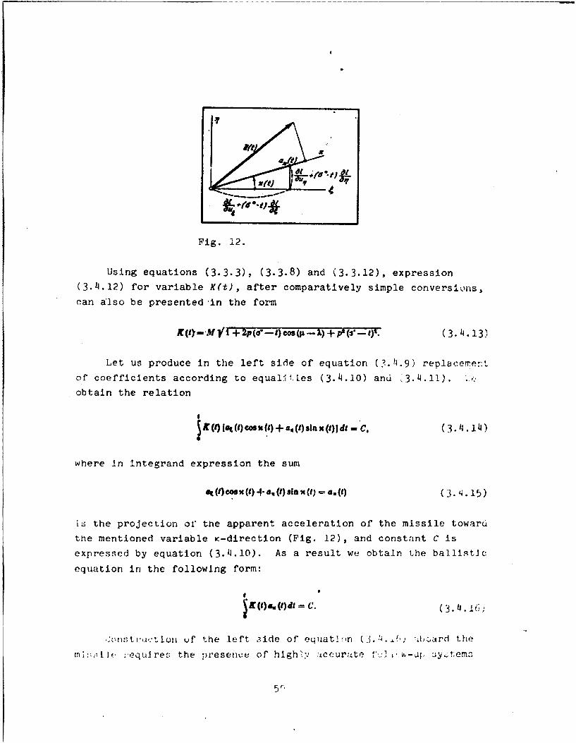
Fig. 12.
Using equations (3.3.3), (3.3.8) and (3.3.12), expression
(3.4.12) for variable K(t), after comparatively simple conversions,
can also be presented in the form
. ++ -(3.4.13)
Let us produce in the left side of equation (3.41.9) replacerer:t
of coefficients according to equali.tes (3.4.10) and ,3.4.11). ..
obtain the relation
JIf()([a(t) cosu(L) + au(L)ss'a()JdS C ( 3.1411)(34.14)
S
where in Integrand expression the sum
a() cos x (t) 4- a, (t) sinxt)= 3 () (3. x1. 15 )
i6 the projection of the apparent acceleration of the missile towaruthe mentioned variable K-direction (Fig. 12), and constant C is
expressed by equation (3.4.10). As a result we obtain the baIlIst~c
equation in the following form:
. ()3. 1I=
,st,,,.'±~tLo uf the left .;ide of equatliln (3. .'-.f, bard the
in:, ;-ilf :equlire£- the presen:e of highly i-ccurate V2 v,;--q. y~tem3
5(,
located on a gyroscopic stabilizer for the change in orientation of
the axis of sensitivity of the meter of acceleration according to
the assigned program.
Of course, approximation methods of the formation of the left
side of the ballistic equation (3.4.16) by means of the usual integra-
tors of accelerations, for example, by means of replacement of func-
tions K(t) and K(t) by their certain mean values.
§ 5. Inertial Control of Range of the BallisticMissile by Means of Longitudinal and
Standard Integratorsof Accelerations
In systems of control of ballistic missiles one can use the
so-called standard integrators of apparent accelerations, the axes
of sensitivity of which are guided in plane &n at the assigned angle
to the axis C according to the progrn of flight. The control of
fiigL' contr'o-s is producn% Jr this case so that together with the
fulfilling of the assigned program of the change in pitch of the
missile (i.e., change in angle between its longitudinal axis and
axis C) the reading on the standard integrator would be reduced to
zero. The angle between the axis of sensitivity of the standard
integrator and axis of the missile itself is selected close to a
straight line.
Mhe ase of the standard integrator of the apparent accelerations
in the system of control of motion of the missile leads to stabiliza-
tion in the assigned direction of the resulting force of thrust of
the engine and aerodynamic forces acting on the rocket. Thus, the
direction of the vector of the apparent acceleration of the missile
(h'v."vcr, of' rourie, ijut its magnitude) is stabilized. With the
kjiu n approximation, being distracted from errors of the system of
eontrol, it can be considered that the standard integrator controls
the flight of the missile so that the projection of the apparent
acceleration on the axis of sensitivity of this integrator would be
'!qua] to zer,_

Let us present in the ballistic equation (3.4.16) of the n
previous section quantity a K (t) in the form of the product C.
S.()-a V)OT ). (3.5.1)
(3
Here y(t) is the angle which forms the vector of the apparent in
acceleration a(t) with K-direction inclined at angle K(t) to axis by
(Fig. 13). ne
of
of
to
Ce
Co
la
\in
ofJ01
Fig. 13. of
mi
Function K(t) is determined by the second equality (3..12), ac
and the direction of the apparent acceleration is changed accord'-rg 0
to the assigned law. Because of this the magnitude of angle y(t) a
:,ould be considered as a known function of time.
Producing in equation (3.4.16) the replacement of quantity
a (t), according to equation (3.5.1) we will arrive at the follow- wn
ing modification of the ballistic equation: its
* Q),*dt m C. (3.5.2) t h,
ur
I, . the alternating coefficient ,b
(1 ) C o s (8) (3.5.3 )_
61
-- i 1

should be considered the known time function for the given cal-
culated case of flight of the missile.
For construction of current values of the left side of equation
(3.5.2) aboard the missile just as earlier (see § 4 of this chapter),
integration of current values of the apparent acceleration, multiplied
by the assigned time function is required. However, now there is no
need in special high-precision equipment for the change in orientation
of the axis of sensitivity of the meter of the apparent acceleration
of the missile. Actually, if this newtonmeter is rigidly connected
to the standard integrator so that axes of their sensitivity would
be perpendicular to each other, then with the proper accuracy of the
control of flight of the missile the apparent acceleration of the
latter (more accurately, apparent acceleration of location of these
instruments) wiii be wholly directed along the axis of sensitivity
of toe mentioned newtonmeter.
w.t! C,: 3-, of accuracy of flight of the missile the newton-
:eter can be fastened directly aboard the missile, the guiding axis
of its sensitivity in parallel to the longitudinal axis of the
mis-ile. The iatter ij ueflected from the direction of the apparent
acceleration of the missile, i.e., from the direction of the resulting
force of thrust of the engine and forces of aerodynamic actions, as
a rule, at small anglec. Because of this, approximately to lay
40MM0).(3-5.4J)
where a0(t.'- projection of apparent acceleration of the missile on
its longitudinal axis.
If, in accordance to the last approximate equality, we produce
the appropriate replacement in equation (3.5.2) and, furthermore,
stihotitute function Q(t) by its certain mean value Q, then we will
jbtaln the approximate equation
, - QvoQ) C (3.5.5)

for the determination of the instant of switching off of the engine
of the missile. Here expression
t
V.(t) S . (t)dt (3.5.6)
is the current reading of the integrator of acceleration with the
axis of sensitivIty parallel to the longitudinal axis of the missile.'
Such an integrator is called longitudinal. As is known, it was used
in the guidance system of the German missile V-2.
Let us return again to equation (3.5.2) and examine additionally
certain approximate methods of construction of its left side on the
basis of current readings
(T (Q)a d(3.5.7)
of the integrator of accelerations with the axl. of' sensiLivity
located perpendicular to the axis of the standard integrator. Con-
sidering the latter equality the left side of equation (3.5.2' is
converted to the form
I"
O f
and can be integrated by parts. As a result, taking into considera-
tion that V(O) - 0, we obtain, according to relations (3.5.8) and
(3.5.2), the ballistic equation in the following form:
q~tVl)- O (tl r() ¢r . (3.5 9)
'Let us note that quantity V0 (t) in equatior, ( because
4.r the variability of direction of the lnngitudinal axis is not theurojection on this axis of the apparent velocity of the missile in.he nonrotating system of coordinates (for more detail on this sep§ cr Chapter I).
6;

The construction aboard the missile of the left side of the last
equation can 3lready be produced by means of only one integrator or
acceleration.
Let us note in conclusion that the same method of integration
by parts can be used for constructing the left side of the ballisticequat.iicn (3.4.16).
!/
II
o ,4
tio.
mem
By
be
the
anJ
C H A P T E R IV
INERTIAL CONTEOL OF THE RANGE OF FLIGHT CF THE C 3.BALLISTIC MISSILE ALLOWING FOR THE
CHANGE IN THE FORCE OF GRAVITY tic)exp
§ 1. One Method of the Solution of Differential whiEquations by Which Isochronal Variations of Tn
Coordinates of the Missile with Its
Motion in the Powered-Flight of
Section Are Determined t-
eng
in the previous cr.dater the basiz tallstlc -.. ,atLion (2.7.6) was ak.
transformed to such a form at which its left side ould be constructed isol
dooard the missile with the help of integrators of accelerations. In we
this case Iscchronal variations of coordinates and projections of
velccity of the missile, which enter into the composition of equa-
tion (2.7.6), were expressed by the approximate equations (3.2.6)
and (3.2.2). This corresponded to the neglect In differential equa-
tions (3.1.3) of terms containing as factors the isoohronal varia-
tions S(t) and Sn(t) themselves. As was already indicated in Chpter
III, the mentioned terms of equations (3.1.3) take into account dur- i n "fig the determination of current coUrdinates cf the rocket changes in
acceleration of the force of gravity because of the noncoincidence of
its actual motion with the calculated. Error appearing from such a
simplification of equations (3.1.3) in the determining of thu range
if flight of the missile is small only at rather small deviations in
its real motion from the calculated. Otherwise It is necessary to of
solve approximately aboard the missile differential equations (3.1.3)
allowing for terrs reflecting the effect of the change in accelera-
tior. , f t:ie fcrcc o" gra',A ty. sol195
u5

Below for tht solution of equations (3.1.3) a similar approxima-
ticn method is used, and it was shown to the author by corresponding
member of the Academy of Sciences of the Ukrainian SSR Yu. D. Sokolov.'
By means of this method the problem of inertial control of range nar
be ,uite accurately solved by the means given in Chapter III withthe help of the application of standard integrators of accelerations
and the simp]est computers.
The Idea of the method consists in the conversion of equations
3.1. ), to their equivalent Integral-differential and integral rela-
tlons with suusequent replacement under the sign of integral of
expressions of Jesired functions by their simplest approximations,
which satisfy, however, initial and final conditions of the problem.
in accordance with this, let us integrate the right and left sides
of equations (3.1.3) with respect to time from the initial instant
t - 0 up to the unknown until the instant of switching off of the
engine t - c, which provides the hitting of the missile on the target.
'zk~ng intc. at- -. ' 1: this se initial co",ditions (3.1.5) forisochronal variations of projections of the velocity o' the missile,
we obtain tw integral-differer.lal relations
In which, similar to equalities (37.2),
Wit(Y)- I&%t)d. av.(4) = I6.,(t) d (4.1.2)
thc lu.curoxal va:-iations of projections of the apparent velocity
of the missile on axes and n at instant t - a.
'See, for example, Yu. D. Sokolov. One method of observedsolved linear integral differertial equations. - Dop. AN URSR,1955, No. 2.
66
I__

If, however, the right and left sides of equations 3.1.3) are
integrated with respect to time twice: one time within the limits
of't = 0 to the current instant t and the second - also from t - 0
to the instant of switching off of the engine t -o, then, taking
account initial conditions (3.1.4) and (3.1.5), we obtain an addi-tional two integral relation:
44 81 () dt2 + -sit a ()dtW.
(3( ) - () + WOW (4.1.3)
where in turn, in accordance with equalities (3.2.6),
8S( )m - Vq(t)d - ! , (f) de
Isochronal variations of projections of the apparent path cf the
rocket, which refer to the instant t - a.
In accordance with the mentioned method, one should 6ubstitute
in the right sides of relations (4.1.1) and (4.1.3) functions 6W(t
unrd 6n(t) by 1heir approximate representations, wfich turn into zero
.t the Initial instant of time and respectively into 64(o) and 6n(o'
when t = a. Then values o' quantities 6C(c,, Sn(a), 6u,(a) and
6u (a), found in accordance with the mentioned relations, prove to
be, as a rule, more accurate than those calculated according to
equations (3.2.2) and (3.2.6), founded uporn approxrmate equalitit.-
(3.2.1).
i possible to take as approximate representations 6t(h,) and
In right sides of relations (4.1.!) and (4.3.3), f'r example,
th. .inear approximation
n7

where o - instant of time for which the determination of dezired
functions is produced; in this case a - instant of termination of
the powered-flight section of flight of the missile.
The best results should be expected with the quadratic approxima-
ti. rn of the form
The reason for this is that functions (4.1.6), unlike functions
(4.1.5), satisfy simultaneously initial conditions (3.1.4) and
(3.1.5), which concern both variations themselves of the coordinates
and their tire derivatives at the instant t - 0. Functions (4.1.5)
do not satisfy initial conditions (3.1.5).
Leacilng to ,in even greater accuracy should be the assignment
of functions 6t(t) and 6n(t) in the form of the following polynomials
of the third power
These polynomials not only satisfy initial conditions (3.1.4) and
(3.1.5), but, furthermore, when t = o turn, respectively, into 6&(0)
and Sn(a) and their derivatives - into Su (a) and 6un(a).
§ 2. Approximate Solution of Differential Equations
for Variations of Coordinates Using the QuadraticApproximation and Also the Approximation in the
Form of Polynomials of the Third Power
Let us examine from the beginning the solution of differential
Qquations (3.1.3) which corresponds to the quadratic approximation
k,;..6). 2uustituting into right sides of reitions (4.1.3)
6

expressions for 6&(t) and Wnt), according to equations (4.1.6),we obtain
64()M a t d I+! ) 0 td. (41.2.1)
Let us introduce here designations
@AS
foe ~ ()- N' (4.2.2)
where, because of relations (3.1.6),
Au () -hat a).(41.2.3)
As a iebult let; us arrive at the two algebraic equal-ions:
with respect Itc the desired quantities 6&(a) and 6ri(a).
Values of coefficients h C&(a), h&n(a) - h n&(a) and h nn () with
an accuracy sufficient for practice can be taken with argument a& 0. Actu~lly, the real duration, of the powered-flight section a
only by a small magnitude is distinguished from the calculated a*.
lsotnronal variations 6C(a) and 6n(a) should also be considered as
small magnitudes. Consequently, the error which occurs from the
mentioned replacement in coefficients h && (), h &n(a) and h n (a),
which sruand In the right side of equations (41.2.41), of' the value of
ar,-u.ewnt a by o*, has thE- second order of smallness.
69

Let us designate coefficients (4.2.2) when a a* by the same
letters but without indication of the argument. With the made
simplifications and replacement of the designation of argument a by
t equations (4.2.4) take the following form:
640 64s) AU6 M+ht-V).(4.2.5)&%Qt) - S, (I) + A4090) +AWA, 0 ..
ihre ,hr h are quantities known for the given cal-
flight f the missile, which are small in comparison with
unity (see . 3 of this chapter). Because of this the totality of
equations (4.2.5) is must convenient to solve by means of iterations,
taking 6E(t) and 6,j(t) in the right side of equations (4.2.5) the
basic expressions represented by equations (3.2.6), namely
At () 4Ms(). 64 () 6S.(IM. (4.2.6)
by subsL'iutirg e expi.'esions intc right sides of equations(4.2.5), we arrive at the following equations for current isochronal
varlation- Df roordinatns ZV() and 6n(t):
(4.2.7)61 () 445 (Iut) t+ A") M. (t)
It iE easy to be convinced that subsequent iterations of equa-
tions (4.2.5) 1eaj accurately to the same equations for 6k(t) and
6n(t), if jnly in the calculations we drop terms with squares and
products , 4 , h -a : , and h n "
To srnirch for \.'rations of projections of the velocity of the
misslle 6U (t) and 6U11(), let us substitute into right sides of
relations (4.1.1) expressions for 6 (t) and 6n(t), represented by
equations of the same quadratic approximation (4.1.6). We obtain
for thv d, .11reu, magrn ude thesi equations
70
I'

8ut (a) a 8V1(a) + at (3)r.',td + Ild~t'd,(..8
& s)o NV 4 M + an@) . (0) ( 4d2 .+
Let us introduce designations
(4.2.91,
. , - -- g,, (a) tIdt.
Then equations (4.2.8) are presented in the form
6n% (a) - 6Vt (a) + gu (s) 64 (a) + g, (a) 6 1 (o), (4.2.10)8u. (a) - av (0)+ gA (a) 8(a) + g,, (a) 6 ()).
Similar to the previous in equations (4.2.10), instead of
coefficients g (o), g,,(o) = g,,(a) and gnn(o), it is possible totake their values at the calculated instant of the termination of the
powered-fiight section of flight of the missile o*. We designate
these values, respectively, by g&, g~n = g., and gnrl" Let us sub-
stitute further into equations (4.2.10) expressions (4.2.5) forvariations of coordinates 6&(a) and 6n(o) and disregard the products
of coefficients g and h with arbitrary indices. Ultimately we
arrive at equations for the desired Isochronal variations of velocityof the missile 6u&(a) and 6un(a) with'respect to Immobile system ofcoordinates &. Changing in them the designation of at.gument a by
L, we obtain
a,,(u ) - 8V () +, u.S (t) + g'6S (), (4.2.11)
,% (t) - 6V, (t) + g48S, (t) + g,,64 (f).
Equations (4.r.7) and ('.2.11) are the app',>lr, ate solution of the
totality of differentia] equations (3.1.3) in a 'Thrm similar for the
71

application ir, systems of inertia] control of flight range of
ballistic missiles.
Somewhat more bulky are equations for isochronal variations of
coordinates and projections of velocity of the missile, if we take
polynomials (4.l.7) for the initial approximations in equations
(4.1.1) and (4.1.3). As a result, similar to the case of the
quadratic approximation, it is possible to arrive at the following
equations for variations of coordinates:
6(t) - (t +3 u- 20) 8S t) + (3. - 2/c.) 8S, (t) ++ VQU - hv) 6v 1 (1) + ** (/to - a V" (1),
bq(t) n(3A- 21,x) 8&(t) + (t + 3..21,..) 6S1 (t) ++ ea- ,- Wit )M + U4. '- kl) 6V,4 (1), (4.2.12)
and for variations of projections of the velocity, correspondingly
8I (I) - (3et - 2t.) 8S& (,) + (3gt.- 2-it,) 8S, (t) +
+ It + 4, iUt - g-)i 8V1 (1) + a. (it. - g-.) aV. (),
6a,, (t) - (3g- 21c) A (f) + (3g.. - 21%.) 8S, (t) +
In equations (4.2.12, and .4.2.13), besides designations already:
introduced in this section, quantities 1 , & F.-r, i PTI and J V
$n, 'qr, $ are valued of integrals
of[" I: = a,74 Oiiadt. ion(e)eh=.\.jIdt,
. \ (4.2.14)
"" *44,(a) t di° :-' "
e O
7;.1

I
which they take with argument a equal t. n*, i.e., at the calculated
instant of switching off of the engine.
1 3. Simplification of Equations for IsochronalVariations of Coordinates and Projections of
Velocity of the Miesile at Extensions ofthe Powered-Flight Small in ComDarison
with the Radius of the Earth
Equations (4.2.7) and (4.2.10) and also (4.2.12) and (4.2.13),
obtained in the previous section for variations of coordinates and
projections of velocity of the-missile, can without great harm for
their accuracy be represented in simpler form, which dces not require
preliminary calculation of integrals of the type (4.2.2), (4.2.9),
(4.2.14) and (4.2.15). Actually, partial derivatlves of the accelera-
tions of the force of the earth's gravity . K T tak
part in these integrals, are functions of moving coordinates of the
calculated motion of the missile and, consequently, finally - time.
However, with a small extension of the pcered-fliht sectior. -f' the
trajectory of the missile, in comparison with the radius of the
e:irth, these functions can be substituted by their values, which
refer to the point of the missile launch, and the derivatives them-
selves can be calculated on the assumption that the earth Is a spherp
with a radial distribution of density.
The last assumption, if one considers equations (2.5.4), leads
to the following expressions for the mentioned derivatives of
accelerations of the force of gravity:
!-Z-ZjLm3I'q (41.3.1)
Here E, n and C - coordinates of the arbitrary point of space
and p - its distance to the center of the earth.
73

For the point of th4 missile launch (see 6 1 of Chapter II) we
have
1-t--0 and -- mR. (4.3.2)
and, consequently, at this point, according to equations (4.3.1),
*h 2 4* .3-3)
where there ;- Inro,:;duced designation
S(43..4)
gY9 "A
In the theory of gyroscopes and inertial navigation quantity
v, determined by equation (4.3.4), is known by the name of Schuler
frequency (v z C.00125 i/s).
Using the approximate expressions (".3.3) for derivatives
and W ir. equalities (4.2.2), (4.2.9), (Z.2.l) and
(4.2.15', we arrive at t..e following simple equations:
hw, () t 's (0) 44 " (0)-O.r,1)-*'FT " 0.A"0
and also
(4.3.6)
Having assumed in these equations o - 0*, one can present expressions
(14.2.7) and (4.2.11) for isochronal variations of coordinates and
projections of velocity of the missile with the initial quadratic
approximation (4.1.6) in the following final formn:

a,(t) ,=[1 ' .1S Y ).- b
6MC () b Or W - 64. (437 b3
ea, (t) = 6V, (j) + 20eS" (1).
Similarly, for the case of the. initial approximation of functions
6 .() and Sn(t) in the form of polynomials (4.1.7), on the basis ofequations (4.2.12) and (4.2.13), we obtain
30(e -last (8) +i + ("), - (t).
[aI)[- 6Y.Vt) + V%. S(t). (4.3.8)6
Equations (4.3.7) or (4.3.8), which approximately consider the
change in action on the missile of The force of the earth's gravity
(because of the wrotion of the missile not according to the assigned
calculated law), should be more accurate than similar equations
k3.2.2) and (3.2.6) given in Chapter III.
§ 'i. Construction of Ballistic Equations in Whichthe Effect of Changes in Acceleration of the
Force of the Earth's Gravity isApproximately Taken Account
In the previous paragraph equations (4.3.,' rnj *zo 4. 4.8)
were obtained for the determination of variationis uV .-oord]lnatc- arif,projections of the velocity of the missile with -. Lppr xirnatecalculation of the effect of the change in the fV'rce of the earth's
gravity with motion according to the law which Is somewhat distin-
guished from the calculated. The mentioned equations allo, more
accurately, in comparison with expres.;Arns 3.3.13'; And '3.4. 't)r
7r5

obta1,jed in Chapter, III, constructing the left side of the basic
ballistic equation (2.7.6) aboard the missile, using readings of
the same integrators of accelerations. For this we will use in the
heginning equations (4.3.7) and substitute into equation (2.7.6)
expressions for 6(t4, dn(t.), 6u (t) and< 6u (t) determined by them;
we obtain
1a'( + ve (e, a +0-T -Of11f~(? a' aq ': , q+
+ t (,) , +I av. (,) 2--
(I- 0) [< (dOf+ 4 :(f) a (4.4.1)
Further, similar to that which was done in § 2 of Chapter III,
let is present variations of projections of velocity SV (t) and
5V (t) in the r-rm of differences (3.2.3) and use equations (3.2.12).
St y L,~: a; JI .- t as In the conversion of equation (3.2.10), termb
standing in the right side of equality (4.4.1) are reduced with
i;'iLar terris of its ieft side. Taking into account still equatiur.-
j.L.7,, we arrive at the equation
I (t);(9) AV + (eSq) -LS)A+ V (1)4..
i ri w.h I c'h
W -- r- W -3- 4- -(4.4.3)
Equa+,ior. (4.4.2) differs from equation (3.2.13) only by• -ffitents of Isochronal variations of projections of the apparent
path 5S (t) and 6S (t). Such coefficients in equation (3.2.13) dre,
rk-spective1y, partial. derivatives Lf and - and in equation (4.4.2)
t

Simiare quantities A' and A' distinguished little from them. Therefore,t n (4.
subsequent conversions of equat on (h.4.2) can be produced exactlyran
as in § 3 of the previous chapter. Then instead of equation (3.3.13),
ofwe will arrive at the following:
iI r {#}~~(8 + 1 M.. M )- 4. (01 - (e,). ..
in
The left sides of equations (4.4.2) and (4.4.4) are zonstructedand
aboard the missile with the heip if the same technical means as for
equations (3.2.13 and (3.3.13), i.e., two integrators of accelera-
tions and the appropriate computer, which includes elements of
repeated integration. In this case the axis of sensitivity of one jee
.,f the integrators is at the same constant angle X to axis as ir
the construction aboard the missile of the left side of equation res
(3.3.13). As regards the axis of sensitivity of the other Integrator, thcthe
the latter should be inclined toward the axis at an angle of u',
which is little distinguished from the corresponding angle ji. Similar
t6 eq- lity (3.3.8) the magnitude of angit .,' Is found from relatic)ns
A = N* cos W. A, wN'sln p'. (.4.)
where, of coairse,
'-4'. ( 4.6)
In turn the coefficient p' Is distinguished little from coefficienL
of equation (3.3.13) and is determined by equation in t
p.7' (.4-.7)
lere quantity M is the same as that in equation (3.3.4).
P ossible also is the conversion of the ballistic equation
(4,4.U) to the form
In I
K'(t)a, (1)* - Co. (4.4.6)
77

similar to the form of equation (3.4.16). The use of equation
(4.4.8) allows solving the problem about inertial control of flight
range of ballistic n'is ]es just as in § 4 of Chapter Ill by means
of one meter of acceleration with an alternating direction of the
a~i r of sensitiv'ty. In equation (4.4.8) the variable coefficient
K'It; is formed by the same equations (3.4.11) as coefficient X(t)
in equation (3.4.16) but with the replacement of angle K(t) by angle
K'!t) and derivatives and A- , respectively, by qaantitles A'and A'..
n
The u6Q In the transformation of the basic ballistic equation
(2.Y.6) of more complex equations (4.3.8) for coordinates and pro-
jecticns of velocity of the missile leads, naturally, to more bulky
results in :;QLparison with equations given in the beginning of this
sectiun. li.ztead of equation (4.4.1), in this case we arrive at
the more coumple× equation
" + M t t -&v3( 01 ~+3~
+ I +.v!!j- +,[t + WS+ +
(4.4.9)
in turn equation (4.4.2) is replaced by the following:
In it these designatio .- are introduced
76

A; f t +--- .o
"; +It + V4.,.S.
Similarly, equation. (4.4.4), when using equations (4.3.8), is
replaced by the following:
V.+() + IS.- ()- S'- (t) = V. () +
+ -- "(B 4 aja) + 3 (4.4.12)
Here A" and p" are directions of axes of sensitivILy of two Integra-
tors of accele-ations, which, respectively, differ little from .-
and P-di'rections, introduced in § 3 of Chapter III. Angles X" and
V", which these directions from with axis , are determined byrelation
Aj-.Novwj: ;- N'sinj ,
Coefficient p" in equation (4.4.12) is expressed by equation
*N-
:'he construction of the right side of the ballistic equation in
the form (4.4.12) aboard the missile is complicated, as compared to
the case of the equation of the form (4.4.4), by thn necessity of
introduction into the computer of an additional tem: linearly
ierendent on time. Finally, Subsequent conversions of equation.
(4.4.12), specifically, to the form similar to the ballistic equa-ti o~14.,4.8) and also (3.,5.2) are allowed.
!n ccnc.iusion let us note that the selection for the specific
s ... !m ,,' control of the C'light range of one of the baliistic
79

equations given in this and previous chapters should be produced on
the basis of estimates of quantities of the so-called systematic
errors inherent to the system of inertial control of the given type
of rocket. Systematic errors are understood usually as those errors
in the determining of flight range of the missile, which appear
exclusively because of simplifications made in the derivation of
the appropriate ballistic equation. Because of this, even with the
accurate switching off of the engine of the rocket at the instant
indicated by the ballistic equation and with the accurate operation
of a13 remaining irstruments and devices of the system of inertial
control, the actual flight range of the missile can be somewhat dis-
tiriguished from that assigned according to the calculation. As
regards to the technical difficulties of the construction of systems
of inertial control of flight range of ballistic missiles, they are
included in the manufacture of meters and integrators of the apparent
accelerations (i.e., newtonmeters and impulse meters) with extremely
small instrumental errors and gyroscopic instruments with minimum
servicing -,ff Lheir stabilIzed axes relative to directions on fixed
3tar. The sa,!ne refers to the immediate switching off of the engine
-,n the signal of the achievement by the ballistic function of a value
%,orrc.-pondirng %o the assigned flight range of the missile.
I,
Lp

sma
cul
Coll
aXful
theHow
misCHAPTER V
aiJ, '-
CONTROL OF LATERAL MOTION Ole THE BALLISTIC MISSILE
] i1
1 1. Lateral Deviation of the Missile from the Target,Expressed in the Form of a Function of Changes In
Parameters of the End of the Powered-FlightSection in the Starting System
of Coordinates mot
tim
In the solution of the problem about the elimination of lateral ran
deviation in the missile from the assigned target, there appear acc
additional aifficulties connected with the fact that cf the duratJctr dur:
of the free-flight section of real motion of the missile, as a dep
rule, is somewhat distinguished from !s calcul3ted value. Tn view tn
of this, control according to the earlier assigned law of the motion
of the missile in a direction perpendicular tc the proprammed plane,
i.e., plane xy of the starting system of coordinates xyz or (i.:i : c
anoteor possible variant) to plane &n -f the nonrotating sys-t em m
tn , in general does not provide the absence of lateral devlati'r,-
in the missile from the target. Really, because of the laws of r'la
mechanics the missile on the greatel part of the free-flight section of
of Its flight is moved with minute deviations from a certain plane,
which does not change its orientation relative to directions at
fixd stars (the mentioned deviations are connected basically wi''
the nonsphericity of the earth). Therefore, if the duration of th. tior
free-flight section is not equal to its calculated value, ther. i, e
because of the rotation of the earth lateral deviation in the negl
missile fror, the target' continuously appears. However, with eart
'An exception Is the ease of flight of a missile in the plane ofti.e equator an from one pole on another.
81

small distinction in the actual motion of the missile from cal-
culated this deviation should also be small. Correspondingly the
control of motion of the missile in the powered-flight section in
a lateral direction can be reduced only to the requirement of the
fulfillment of an earlier assigned (calculated) law of motion in
the projection on the z axis (or in another variant - on axis i).
However, for a more accurate elimination of lateral deviation in the
missile from the target it is necessary to take into account how
at current instant of time its real motion in a longitudinal
ilrtior is distinguished from the calculated. For this nurpo7e
nw car, use current readings of instruments of the control of
]iizht range 3f the missile.
It is obvious that an especially accurate control of lateral
motion of the missile is necessary only during a short interval of
time when cutoff of its engine can occur in flight at the assigned
range. At the remaining time of the powered-flight section the
accuracy of control of lateral motion can be somewhat less. The
durattot. of the mentioned interval of allowed cutoffs of the engine
depend on the quality of control of motion of the missile according
to the assigned program.
In the starting system of coordinates xys (see § 1 of the
second chapter, Fig. 9) quantity b - of .lateral deviation in the
mirsile from the target, just as the range Z-" is a function of
coordinates x, y, z and projections vx, vy, V of its velocity
relative to this system of coordinates at the instant of termination
of the powered-flight section of the flight. Thus,
b-b(-b(s, s, , , ) (5.1.1)
The asti.onomical time, which corresponds to Instant of termina-
tion of the powered-flight section, does not play any role here as
in equation (2.1.2), unless one does not take into account the
negligible effect of such factors as the mutual arrangement of the
earth and moon or the earth and sun.
82

With the replacement of arguments of functlon (5.1.1) by their
calculated values x**,Y B*, V*J v*, and v: it should turn intoX Y
-zero, since the lateral deviation in this case is absent. Thus,
b (z, Y', ;., ;. V;) = 0 (5.1.2)
and, consequently,
AM = b(, . . , ,, v)-b(z' 3'. , v, . v) b, ( 5.1. 3)
I.e., the error in the lateral deviation Ab is equal to the latera:
deviation b.
In accordance with the Taylor series for the function of' many
variables, we have, correct to smalls of the first order InclusivelN,
the following expansion:
ab 81+ (V. -' + op. - e.) + (V, - v'-:) 5 .
Here derivatives Ob 81 t ab q r ken at cal-
culated values of their arguments and, conrc'erIt~v, '-r eacho alculated case of flight of the misslLv are. earl<:. icRvwn quantities.
'h-:-y can be determined in a way similar t- the ta 2T1 ttI >,_ffic en-
rv-r 'it, 4 1 of the second chapter.
5 2. Lateral Deviation as a Funct'cr. or a-:,etev'of the End of the Powered-Flight Section in
the Nonrotating System of Coordinates
In examining the problems of inertial control '..era]
mtior, of the ballistic missile, the starting system .c,.rdi -e,9
1.- ;nconvenient. Therefore, let us Introduce the same . -" *
5Vstem of coordinates & as that in the examining of the th( . :Inertial ountrol of range (see § 2 of the second chapter). Current.oordinates x(t), y(t), z(t) and projections v(t) , v (t) and Z(t)
L:f t:c v,)clty of the missile relative to the starting system of

coordinates xyz are expressed in this case by current coordinatesUt), n(t), (t) and projections u (t), un (t) and u Ct) of the
velocity of the missile in the nonrotating system of coordinates&n4 by equation r (2.2.5) and (2.3.5). Entering into the mentionedecuations also in evident form (through angle * - Ut) is time t, whichpassed at the instant of launch of the missile. In view of this,in accordance with equation (5.1.1), the magnitude of lateraldeviation in the missile from the target can be represented in thefor. of a function'
b -b(L 1% Lut. u.. uc, ) 2. 1
ol' ccordihat- &, r, C and projections u, u., u of the velocityof the miselle relative to the system of coordinates &nC at theinstant t = a of termination of the powered-flight section and alsoi2s very duration a.
Calculated values of coordinates x*, y*, a* and projectionsv*, v*, * r-f velocity of the missile relative to the starting
system xyz correspond to certain calculated values of coordinates&*, n*, 4* and projections u, u , u, of velocity of the missilein the nonrotating system Cnt. It is obvious that function (5.2.1),which represents the lateral deviation of the missile from thetarget, will turn Into zero at these values of their arguments if,furthermore, we assume the duration of the powerEd-flight sectionis also equal to its calculated value a*. Thus,
b(P,, , I ', u,u; d)inoO. (5.2.2)
Expanding function (5.2.1) in Taylor eries and being limitedin the latter only by terms of the first order of smallness, weol. tan, takIntrg Into account equality (5.2.2), the equation
b=(-- +6 (+.-- )b +( - b) +
"U + (5.2.3)
1 11ere-, Ju t in § h of the second charte-, ef'Ia 40ns2.4.1) ,L ',.':'-rted.
.14

in which partial derivatives -1 91 ' - and . are magn
constant coefficients, since their arguments , n , U u, , It a
and a are taken equal to their calculated values, i.e., respectively swit*, n 8 , J , , U u and a*. Magnitudes of these - effl lents
depend finally on the selection of a certain calc:.ated case of
flight of the missile. In a way similar to the appropriate partial func
derivative of function Z, which represents the flight range of the sign
missile, they are expressed by equations of the type IZ.4.5) and This
(2.4.6) In terms of partial derivatives a. '." o-. "-turn
and also quantities x, y, at, v*, V, 4 . magnX ' X deri
Equations (5.2.3), correct to squares and products of differences
9-- l q-q. C-V, t u-U. U. .- 4 &-s,a-g , determines the lateral
deviation in the missile from the target when magnitudes of coordi-
nates and projections of velocity of the missile at the end of the
powered-flight section are not equal to their calculated values,
of I
With real motion of the missile neither the Instant o1f --witching of f
off of the engine a nor its coordinates C, n and prnject-on of maki
velocity u,, u,,, which correspond tc this Instant of time, are
known earlier. Therefore, for elimination with the abrve-mentioned
accuracy of lateral deviation in the missile from the target, a
continuous change Is necessary in quantities r(t) and u, (; charac-
terizing itc motion In a lateral direction during a certain time
interval of the end of the calculated powered-flight section. The
purpose of such a control is the continuous reduction to zero of the
function missi
no nro
PQ) (('-~ ~+ Aoe-,iJ~ + 10)-~ VIA +
r,, tI't wth,,le !.terva) of possible instants of the switching -f f an r
tnt. engine f' r a missile of the give, system. Actually, functio.outt.1TK C cni

0(t), according to equations (2.4.1) and (5.2.3). turns into the
magnitude of lateral deviation in the missile b If we assume in
it argument t equal to the actual value of the instant of the
switching off of the engine a.
The current value of function a(t), which we will call the
function of LateraZ deviation, can be used as the controlling
signal in the system of control of lateral motion of the missile.
This system should operate in such a way that function B(t, would
turn into zero because of the corresponding change in current
magnitudes of the coordinate of the missile C(t) and its time
derivative u (t). C/§ 3. Construction of Corresponding Terms of the Funccion
of Lateral Deviation Dependent Only onthe Basic Motion of the Missile
As was shown in the previous section, for the Inertlil control
of lateral motion it is necessary to reproduce the currei:t value
of function 8(t) aboard the missile. The totality rf te ms (5.2.
making up this function is decomposed into two groupF k1 t) and
6't). The first of them is the sum
I () -I|() rl 2t- + lIn (M-no
U; I t+I,' -
the magnitude of which is determined by the basic motion of the
missile, i.e., by the motion of its projection on plane '.n of the
nonrotating system of coordinates t. The second group
ccnsists of two terms containing, regoectively, quant1'
and u (t;.
Some methcds -f the construction f tie current value f
function La(t; abcard the missi. - are examined In the r .wling
8 6_

.ection. As regards the sum (5.3.1), thpn it, according to its
struc:ture, is completely similar to equation (2.4. 9 ) for the initia]
ballictlc function e(t). Therefore, the approximate construction
of the sum (5.3.1) can be produced aboard the missile by the same
methods as were used for the construction of function c(t). Let
us examine, for example, the construction of' this sum aboard the
missile by means of using readings of two integrators of accelera-
tions, the axes of sensitivity of which are oriented respectively
parallel to axes and n of the nonrotating system of coordinates
&n . Similar to equation (2.7.4), the sum (5.3.1) can be represented
in the form
&M) , [| t)- " O)M +[I)NFR
-+
+11" (8)- l'11 + I q'( M-"*'I J + I a; M)- ";1 I +
+ a3 + '(5.33)
With subsequent conversion of the sum 81 (t) we will use equations
(2.7.1) and (2.7.2) for Isochronal variations of coordinates and
projections of the velocity of the missile and also equations of the
expansion in Taylor series (being limited only to terms of the
first order of smallness)
r(-"- M r )- (o - (CO-f) t- )!," (5.3.4)- i(t)- -. q(1) -()=(- 9-ac_,
and in exactly the same manner b
i~ a.; M - U; - U (,)..- ; (0') -V ( 0 ai- d '- -- -- ~ -- ,
m,* (1) -. ,* = U,4 (t)- ,,; (0') = (*-- ) . .
Taking into account, furthermore, that in accordance with
(2.6.3)
P7

-d8 - (5.3.6)
we tr'ansform the expression for sum (t) to the form
a6 OU Gb
'I8u (I) -+ _,. r -*J + ., *a!t ,
*4.(e 0 _~(a*) ab+ + + t (53.7)
Just as in the third chapter, let us disregard in the beginning
the effect of the change in the acceleration of the force of gravity
during motion of the rocket not according to the calculated law.
In accordance with equations (3.2.6), (3.2.7), (3.2.2) and (3.2.3),
we obtain at small values of the difference t - a* relations
It k(8) = ()- s)-& t 0S(' +
+ (I V; (d). (5.3.8)
8, ()-&S, (t) = S,)- (t) W S,(t)IS. (') ++ (17- - ) v6.(')
and also
au(t) 6v,(,) - (t)- V(t) = V,()- K. () +
+ (t- d') 40(')1.- (5.3.9)
Used here again are equations of the expar.;.Ion in Taylor series,
but for projections S; (t), s(t) of the apparent path of the missile
and projectionn V. (). I* () of Its apparent velocity in the calcu1ntedrnwt tor, equations (3.2.5) and (3.2.9) are taken Into account.
By mean- of equalities (5.3.8) and (5.3.9) the sum (5.3.7)
is reduced to the form

No)- +(,) + $1() + V() + V . ) +
dtL--- --- "(3') V. +
I tIn the last equation we can produce further simplifications, since, det
according to equality (2.6.1), we have
- (- 1 1t)" , "(t); LI, one
rep-(." (0); 1 ( 5.3.11) con
chaas a consequence, as a result of the integration with respect to are
time within limits of t - 0 to t - *, allowing for equations
(3.2.5)
pro
, , +(I eoxp
dev
(5.3.12)
Equations t-.3.lI) and (5.3.12) can be used in the subsequent
conversion of t-xpression (5.3.10) for the sum 8 1 (t). As a rczult
let us obtar. the following final expression for this s'Jm:rel -
reacp,-&(t) + s% M,)-t+V 1 ,()a
-C+ (I-a')D. (5.3.13)
Introduced here are des ignations
C sikA S 3) + V 31A +forou
the

D = 4It+ i*'~ u
+h , (t ), 1 " (;'): I W + 1. " ('), " (T') ! 31 +
+ . Ob --dt-. - (5.3.15)
It is obvious that C and D are constant quantities, which can be
determined earlier for each specific case of flight of the missile.
For the construction of expression (5.3.13) aboard the missile,
one can use the same integrators of accelerations and elements of
repeated integration as in the solution of the problem on inertial
control of flight range by the method given in 5 2 of the third
chapter. Furthermore, an additional computer and clock mechanism
are n:ecessary here.
If, however, the control of flight range of the missile is
produced with the help of integrators whose axes of sensitivity
are ,ara'le' to X- and u-directions, then for the fcrmation of
expression (5.3.13) there will be required, furthermore, an auxiliary
device of the type of converter of coordinates, which continuously
solves the system of equations (see § 3 of the third chapter)
VjLt)coa L + V,(t)sin % - VI(t),
Wt (I) @03P + V,(1)i 31 up V4.(1)
relative to quantities V (t) and V (t) according to data of current
readings V (t) and V (t) above-mentioned Inte-rators.
§ 4. Construction of Main Terms of the Functionof Lateral Deviation
7he second group of corresponding terms of equation (5.2.4)
for firction B(t), as was indicated in the previous section, is
the su:.. f two terms
and I ( - , ---Og. (5.4.1)
II

They can be called the main terms of the function of lateral
deviation P(t), since they play the main role in the control of
lateral motion of the missile.
For the construction of current values of the sum (5.4.1)
aboard the missile, one can use readings Vt(t) of the integrator
of accelerations, the axis of sensitivity of which is oriented in
parallel to axis t of the nonrotating system of coordinates &nC
(so-called lateral integrator).
Let us note that, according to equation (1.4.1) (§ 4 of Chapter I),
there occurs the relation
,t )(5.4.2)
where a (t) - projection of apparent acceleration of the missile
on axis 4, and f- projection on the same axis of acceleration of
the force of the earth's gravity. Thd latter, similar to equations
(2.5.4), with sufficient accuracy can be represented in the for
(5.4.3)
Thus, relation (5.4.2) can be considered the differential equation
in the desired function i(t).
At the instant t = 0 the axes of the starting system of coordi-
nates xyz, which is connected to the eart respectively coincide
with axes of the nonrotating system Cnt, and the center of masses
of the missile, on assumption, is found at their common origin.
Furthermore, at this instant the missile does not have velocity wlth
rPespcet to the stft1 nr system of r--dinates xu . Corrauently,
InItia] conditions of equation (5.4.2) are such:
-Co =0 o..=,()= (5. 4.4a)
where - velocity of the beginning of the starting system of
coordinates in the nonrotating system &n at the inntant when
9'

I f
t = 0, i.e., at the beginning of the powered-flight section of
its flight.
It is possible to assume that the acceleration of the force
of gravity proves to have an insignificant effect on the rate of
change in function (t). Therefore, as a first approximation it
is possible not to consider the projection f in equation (5.4.2)
and, respectively, consider that
M-() (5.4-5)
Hence, taking account the second initial condition (5.4.4), we have
-t - VC(,) + t. (5.14.6)
Here
w (,) a () t (5.4.7)
Is the current value of the projection on axis of the apparent
velocity of the missile relative to the nonrotating system of
oeordinates Cnc. This is the reading of the integrator of accelera-
t!..is with the axis of sensitivity parallel to the axis . Secondary
integration of' both parts of equality (5.4.5), allowing also for
the first of the initial conditions (5.4.4), leads to the equation
(8)- s(9) + , (5.4.8)
in which S (t) - projection on axis t of the vector of the apparent
path of the missile in the nonrotating system of coordinates &n .
In accordarice with the last equation, for the construction
a .c-'urd tle missile of current values (t), an additional integration
-f readings of the aforementioned integrator of accelerations is
rntce.sary. Actually
t
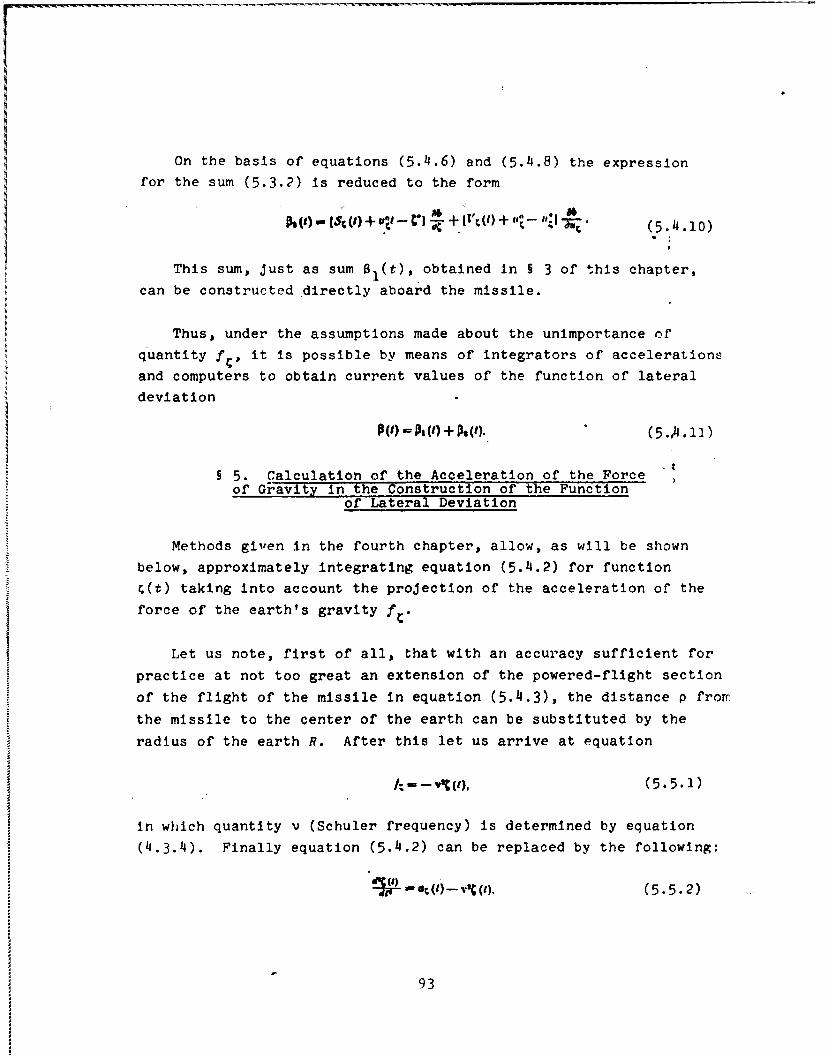
On the basis of equations (5.4.6) and (5.4.8) the expression
for the sum (5.3.2) is reduced to the form
(5.4.10)
This sum, just as sum 01(t), obtained in § 3 of this chapter,
can be constructed directly aboard the missile.
Thus, under the assumptions made about the unimportance of
quantity f,, it is possible by means of integrators of accelerations
and computers to obtain current values of the function of lateral
deviation
+ ).(5..1)
§ 5. Calculation of the Acceleration of the Forceof Gravity in the Construction of the Function
of Lateral Deviation
Methods given in the fourth chapter, allow, as will be shown
below, approximately integrating equation (5.4.2) for function
c(t) taking into account the projection of the acceleration of the
force of the earth's gravity f{.
Let us note, first of all, that with an accuracy sufficient for
practice at not too great an extension of the powered-flight section
of the flight of the missile in equation (5.4.3), the distance p frorr
the missile to the center of the earth can be substituted by the
radius of the earth R. After this let us arrive at equation
(5.5.1)
in which quantity v (Schuler frequency) is determined by equation
(4.3.4). Finally equation (5.4.2) can be replaced by the following:
.(t)-v% (t). (5.5.2)
93
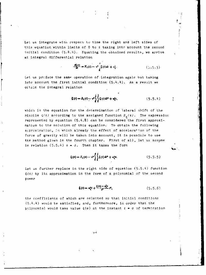
Let us integrate witi, respect to time the right and left sides of
this equation within limits of 0 to t taking Into account the second
initial condition (5 .4.4). Equating the obtained results, we arrive
at integral different'al relation
VC (1) -V t i+ tilt (/ 3)
Let us prcduce the sam- operation of integration agair but taking
into account the first initial condition (5.4.4). As a result we
ottain the integral relation
C., (t), d + ic, 5.5.49 P) - U.1
which is the equation for the determination -f lateral shift cf the
missile r(t) according to the assigned function S (t). The expression
represented by equation (5.4.8) can be considered the first approxi-
mation to the solution of this equation. To obtain the following
arprcxlnation, -n which already the effect of acceleraflon of the
force of gravity will be taken into account, it is possible to use
the method given in the fourth chapter. First of all, let us assume
in relation (5.5.4) t - *. Then it takes the form
(a) - S;(a) - V C () del + "t-. (5.5.5)
Let us further replace in the right side of equation (5.5.4) function
C(t) by its approximation in the form of a polynomial of the second
power
(9) - vt + -- it--•.(5. 6)
the coefficients of which are selected so that initial conditions(5.4.4) would be satisfied, and, furthermore, in order that the
polynomial would take value (o) at the instant t - o of termination
4

of tlh powered-flight section of real r tJcii of the mJisile.I
if' then we produce a similar replacement also in relation
(5.5.3) and accomplish the necessary operations of' Integration,
then we will arrive at equality
U(a)s V ()- V'uO -- V2C (a). + U-,(5. 5.7)
which can be examined as the equation for determining the value of
the function It:elf r(a) and its time derivative u (a) at the
instant t
The solution of the second equation (5.5.7) can be obtained
with sufficient. acruracy if in its right side quantity C(a) is
substituted by its first approximation, according to equation
(5.4.8), i.e., If we assume
(a) - S(a) + ur d. (5.5.8)
A.; a result we obtain equation
C (a) Tu ri
IV. produce the same replacement in the first equation of 13.5.7).
'inally we arrive at the following approximate equation for the
i '.ermination of the projt'-ctin of the actual velocity of the
:ni: sile on axi- .'
3 T) (5.5.10)
Conlauering the argument a to be close to a*, it i: :.s1bi;
'fltf.YUt great loss of accuracy in equations (5.5.9) and .5.10)
I. is a possibility, 71miiar to § 1 of the fourth 2hapter, )f-n. rfpr-oxlmation by means of a polynomial of the third nower Irwiiich the, derivative when t = a still turns into 4(o'.

2
to substitute argument a in terms containing the small factor v2,
by the rated value of duration of the powered-flight section a*.
Substituting in other places of these equations argument a for the
current time t, we obtain the following final expressions for C(t)
and u (t)
['-r.V)_0)_ 8C 1) +(5-511)
:qua tions (5.5.11) lead to a presentation of the sum a2 (t), more
a.ccurate in comparison with expression (5.4.10), namely:
{[,c- "'"-+ {Vd()-T :(+ [t"-- ;-k.5.5.12)
The construction of function W2(t) aboard the missile can be
prcduced by means of the integrator of acceleration with axis of
sensitivity parallel to axis (and also, of course, the integrating
devi ce).
In t ;is hoIL, as wa- already Indicated in the introduction, an
-oriunt of problems of the thc-ry of inertia, 'rlro! flight
.- balli;tic ~riitles was produced under t .:,.urption of the ideal
:tabillzatlcn :f axes of sensitivlty )f '.wt( . eters and Lntgrators
'f accelerations and completely accurate cper-!t on of the latter,
.e., accurate indication by them of current values of projections
,)f 'hw. vo'tm, fr :ppirent acceleratlon of the missile and 'nterrPIsL, f t' ,. L V, Il L', -..
Af estim.t- _,f the effect of instrumental errors of gyroscopic
,, -c ;-.i Ii rators of accelerations on th niar.,.,,e possle.t M. ' , z,'sIe le wltt> , ht at the ,s, I - .',t ,nd also

an analysis of causes of the appearance of these errors and develop-
ment of measures on their elinination represent an independent
interest and fall outside the framework of this book.
Let us note, finally, that problems of inertial control of
space missiles can be solved by the same methods as the problem
examined above about the flight of ballistic missiles within limits
of the earth.
97

APPENDIX
DERIVATION OF EQUATIONS FOR COSINES OF ANGLES BETWEENAXES OF TWO SYSTEMS OF COORDINATES TURNED RELATIVE
TO ONE ANOTHER AT A FINITE ANGLE
In manuals on analytical geometry and according to theoretica2
mechanics, equations for the cosines of angles between axes of two
systems of coordinates arbitrarily turned relative to each other arederived usually with the help of several additional geometric con-
structions. The derivation of these equations is also possiblec5" reans_ of the frcquent use of tables of cosines of angles between
axes of the basic and auxiliary system of coordinates, each ofwhich is turned relative to the previous around one of the coordi-
nate axes' common with it. Specifically, the main axis of rotation
is simultaneouslyI the axis of coordinates of two auxiliary systemsturned one relative to the other at the same angle as the main
axes.
Given below Is a purely analytical derivation of the mentioned
equations, founded exclusively on the simplest theorems of
analytical geometry, and some of these theorerr..- are used in
vectorial form.
lct u- asut-t that the system of coordinates &nC is turned at
an arbitrary angle 0 around a certain axis d, which passes through
'See, for example, Whittaker. Analyt!3al Kinetics. M.-L., 1937and A. Yu. lshlinskiy. Mechanics of Gyroscopic Systems. Izd-voAN S7SP, 1963.
98-
-J

the origin of this system.' The final I.osition of the system is
designated by xyz. If Z, m and n are -osines of angles which form
the mentioned axis of the final turn d with axes of the system of
coordinates 4, then it is obvious that the same magnitudes are
respectively cosines of angles between the axis d and axes of the
system xyz. Specifically, we have
A - oa. (1)
where a - angle which forms the axis of rotation d with the axis
of the system of coordinates n and simultaneously the same axis
of rotation d with the x axis of the system xyz (see Fig. 1h).
I
~Fig. ii4.
X~ ..he .2
Let us designate the direction cosines of the x axi3 relative
t the system of coordinates &nC respectively by a, b. and c. They
are In this case the desired quantities. Besides the apparent
quality
(2)
'In §§ 2 and 3 of the second chapter of this book such an axis.. the nxis of rctation of t.c earth, and angle I -..,as the product)f the angular velocity of the earth U for time t, which passes fromthat instant when the axes of systems of coordinates nr, and .yz,
r .,,r l v.]:.. , c-oincided.
the direction cosines a, b and c sacisfy also the relation
a+ mb +nc=l, (3)
which, in accordance with the known equation of the analytical
geometry, expresses the magnitude of the cosine of angle a between
the x axis and axis of rotation d.
For the determination of the three desired quantities a, b and c,
one equation is necessary. Specifically, it can express the factthat plane xd is turned relative to plane Cd about the axis of
rotation d at the assigned angle C, Thus the measure of the dihedral
angle between the mentioned planes also should be equivalent to
angle €.
Since the dihedral angle is measured by the angle between two
perpendiculars to the planes forming it, then we will introduce
two vectors h and T, the first of which is perpendicular to the
plaine Id, and the other - plane xd. According to the property of
&.e scalar pr :,ct of two vectors, we have
kcosp -hk + hk, + hk, (I4)
where h, h h - projections on the axis E, r, of vector T
and, respectively, k, kn, k4 - prol'ctl-ons or these axes of vector
Let us take as vector T the vectorial pr:.cuct of the single
vector To, located on the & axis, and sIngl- vector ao, whi!h
possesses the direction of the axis of r.,tatn n d. Projections of
the first of them on axes &, n and C, of course, are equal,
rca.pectively, to numbers
1,0,0, (5)
ar:.A C'!' the secold
,m, n.
.rd I I V,' th.' compe Itio,, 'tf the vectoz:l i -rcd, 4t,.",±,tai i

M. (
and, consequently,
lk~o.h,--n . (8)
In turn for vector we take the vectorial product
i-'x -.! ;' • (9)
Here the second line of the determinant is made up of projections
of the single vector x0 on the axes C, q and c, equal, of course,
to the direction cosines of the x axis in the system of coordinates
Expanding the mentioned determinant, we arrive at the followinz
equality:
4mb-se ,,--ofc-na. k--ma-fb. (10)
Moduli of both vectorial products (7) and (9) are identical
and equal to the sine of angleod between axes & and d or, which is
the same, between axes x and d. Thus, taking into account still
another equation (1), we have
k me--Sag-1T7'. (AW)
By means of equalities (8), (10) and (11) relation (4) can be
presented in the form
(I - P) co - - I (nb + ne) I ('+ m'). (12 )
It. is the deficient third equation, besides equations (2) and (3),
for the search of the three unknown cosines a, b and c, which
determine the direction of the x axiz' with respect to axes of the
-j:steTr of coordinates n•
101

According to equation (3), we have
Furthermore,
no+ lo - is. (14i)
Taking account the last two equalities in equation (12), we obtain
after reducing similar terms to the equation for one of the desired
quantities
a - Coeq+P(1am 4F. (15)
TO determine quantity b, we exclude from relation (2) cosines
a An~d o by means of equations (12) and (15). As a result we arrive
at the quadratic equation
which after simplif'ications with the help of relation (14) is
reduced to the form
bl-2h Lu (t - cos j) +Pm' (I -coon y)'-m' vie' y''0. (i7)
-'f the two rcuots *_.f this equation
b, hn (t - ON ) + a do 1.
e :;hould di cuss the first. Actually, assuming specifically,
we u~aln accordingly
-+,b,-. (20)
.- . ~-'44

However, taking into account the accepted designations (see Fig. 14J),
we have in this case
b .can Xq -+I (21)
and, consequently, the second root of equations (18) should be
dropped. Thus, in general
b - o - 08) 4-n in T- (22)
Substituting now expressions (15) and (22) for a and b into equation
(3), we will arrive at the following equation for the determination
of quantity c, namely:
e - In(I - co) - msin . (23)
Similarly cosines of angles between the y axis and axes ~Sand further between the z axis and the same axes Fr are
Jptermined. Finally, the table of cosines of the angles between
axes of the system of coordinates xyz and &n can be represented
In the following form:
6(1-cOBMy)P+ (1-cosF)nd4 (I-ow)ni-+ oaf + naing -Maingp (fco.Yl-(1 -COSY)M'+ (I-cA34)mn +
''C0-.o'y)lIa+ 0 - Cos) il V Tles) n'++ing -lai M + Cos qP
AFi table was used In the second chapter )f this ! ,ok.
103

BIBLIOGRAPHY
1. Apazov R. F., Lavrov S. S., Mishin V. P. Ballistikaupravleniya raket dal'nego deystviya (Ballistics of the guidance oflong-range missiles). M., izd-vo "Nauka", 1966.
2. Balk M. P. Elementy dinamiki kosmicheskogo poleta (Elementsof dynamics of space flight). M., izd-vo t1Naukat', 1965.
3. Bulgakov B. V. Kolebaniya (Oscillations). M., GITTL, 1954I.
11. 111~<'~ . 11. Osnovnoy kurs teoreticheskoy mekhaniki(Fas~c course in theoretical mechanics). M., izd-vo "Nauka", 1966.
5. Galveri Dzh., Braun S., Vil'yams I. Teoriya avtcmaticheskoynavigatsii s pomoshch'yu dinamicheskikh izrnereniy (Theory ofautomatic navigation by means cf dynamic measurements). - 2c2-1*ctton"Prohiemy inertsial'noy navigatsii". M., IL, 1961.
6. !antmskh-' r. T4. lovlr L. M. Ob uravnerniyakh -,vizteniyarl I-,ty. Prik_. rrL F-. ', 7p (On equations of motion of a
3. jord':,'e", A. I. Avtoriomnyye S'..Gul-ravleniye bal-listicheskikh raket (Autonomous systems if tihr guidance of tallisticniissiles) . M. , Voyenizdat, 1961J.
V. fli t rlyovskly A. A., Kosho~vc'y V. Ni. O'snovy teoril poictara~e~ (~.icp~~'of the theory of flight of Misl< .,~. Voyenizd~it,
196 'i
10. Idell'sori N. 1.Teoriya notentsiala I yeye 'rTe1:v( prosam geofizi1ki (Thecory of potential and its ar"tion lo
1p.-c.Ierns of r e -rhysics,). L.-M., GTTI, 19331.

11. Inertsial'nyye sistemy upravleniya (Inertial guidancesystems). M., Voyennoye izd-vo Minist. oborony SSSR, 1964.
12. Ishlinskiy A. Yu. Mekhanika giroskopicheskikh sistem(Mechanics of gyroscopic systems). M., Tzd-vo AN SSSR, 1963.
13. Ishlinskiy A. Yu. K teorli girogorizontkompasa - Prikl.matem. i mekh. (On the theory of the gyroscopic horizon compass -Applied mathematics and mechanics)., t. XX, vyp. 4~, 1966.
14. Ishlinskiy A. Yu. K teorii giroskopicheskogo mayatnika.-Priki. matem. I mekh., (On the theory of the gyroscopic pendulum-Applied mathematics and mechanics), t. XXI, vyp. 1, 1957.
15. Ishlinskiy A. Yu. Opredeleniye mestopolozheniya dvi-zhushchegosya ob"yekta posredstvom giroskopov i izmeriteleyuskoreniy - Priki. matem. I mekh. (Determination of the location ofa moving object by means of gyroscopes and acceration meters -Applied mathematics and mechanics), t. XXI, vyp. 6, 1957.
1i6. Kooy Dzh., Yutenbogard Dzh. Dinamika raket (Dynamics ofmissiles), M., IL,, 11949.
17. Kosmicheukaya tekhnika (Space technology). M., izd-vo"Nauka" , 19('4.
18. Lakhmin L. M. Svobodnoye dvizheniye v pole zemnogosferoida (Fe mnotion~ in the field of the earth's spherotd).V.Fizmatgiz, 1963.
19. Lur'ye A. 1. Analiticheskaya mekhanika (Analyticalint',.hanics). Fizmatgiz, 1961.
20. Mak-Kiur. Teoriya inertsial'noy navigatsii (Theory ofinertial navigation). M., izd-vo "Nauka", 1964.
21. Pogorelov D. A. Teoriya keplerovykh dvizheniy letatel'nykhapparatov (Theory of Kepler motions of flight vehicles). M.,Fizmatgiz, 1961.
22. Russel W., Rocket Society. ABS SemiAnnual Meeting, SanSan Francisco, California, June l0th-l3th, 1957.
23. Hugley V., .Vudberi R., Govorka Dzh. Inertsial'nayanavigatniya (Inertial navigation). M., IL, 1958.
214. Wrigley W., Schubr. Tuning Characteristics in Navigationin~strumenats. - J. of the Institute of Navigation, December, 1950.
25. Slater T. M. Wich Accelerometers for Spacecraft GuidanceAerospace' Electronics, October, 1960.
n;6. Slater T. M. Measurement and Integration of Accelerationin inertial Navigation. - Transactions of the American Society of'echani-al Englneers, 79, *!o. 7, Ontober, 1957.

27. Sokolov Yu. D. Pro odyn metod nablyzhencgo rczv"yazanlyallniynykh integral'nykh ta dyferentsial'nykh rivriyan'. - Don.AN URSR, 1955, No. 2.
28. Sokolov Yu. D. 0 metode osredneniya funktsional'nykhpopravok. (On the method of averaging functional corrections). -Ukr. matem. zh., 1957, t. IX, No. 1.
29. Sretenskiy L. N. Teoriya n'yutonovskogo potentsiala(Newton potential theory). Gostekhizdat, 194 6.
30. Stlirf.. E. Kosmicheskaya navigatsiya (Cosmic navigation).M., Voyenlzdat, 1966.
31. Suslov G. K. Teoreticheskaya mekhanika (Theoreticalmechanics). M.-L., Oostekhizdat, 1946.
32. Utteker. Analiticheskaya dinamika (Analytical dynamics).M.-L., ONTI, 1937.
33. Feodos'yev V. I., Sinyarev G. B. Vvedeniyc v raketnuyutekhnlku (Introduction to rocket technology). M., Oborongiz, 1961.
2

UNCLASSIFIEDsecurily c Iia ctiofat
DOCUMENT CONTROL DATA . R & D(Scurlty classlleatoe" of title. bo. of abstact and Onrf0eund annotation mus, be wnlred when the evertll repovris cla.eflled
I OIGINATING ACTIVtTV (C O rott*athoNr) IS8. REPORT SECUNITY CLASSIFICATION
Foreign Technology Division [UNCLASSIFIED
Air Force Systems Command 2b. GROUP
U. S. Air Force3 NEPOPT TITLE
INERTIAL GUIDANCE OF BALLISTIC MISSgLES
, Ot9AgC obTIV9 NOTES TMwpe of ep ort and 0pe lFgure ddt.)
TranslationII .u 1 Onts) (Po'et nma.. -Mddl Ingletf. lost name)
Ishlinskiy, A. Yu.* REPORT DATE
Va. TOTAL NO, OF PAGES . "FS
"1968 o6 33e., *.CONTRACT ON GRANT NO.
a. ONIGIN&TONI REPORT NUMLPRISI
b, PROJET NO. 605020FTD-~MT-2P -2q-70
ft'b. OT NE N REPORT NOe l)(Any etA , m n wra that may be e ffne cd
DIA Task Nos. T65-05-20 and IR 00i869T69-13-oi. Q2. 03- 0I 70
. , IT UTION STATEMENT
Distribution of this document is unlimited It may be released tothe Clearinghouse, Department of Commerce,for sale to the genera.public.
UP-LEMENTARV NovesE It. SPONSORING MILI Ar -IY 11
Foreign Technology DivisionWright-Patterson AFB, Chic
Th l.; monograph dis u;sc-6 the m,4thematical principles of certair!allowed variants of inertial guidance of the flight )f balli l "
missIcs,i.e., control without the use of any extern.L *rormatlc(radio signals, radiation of stars and others). It i.' asCuMedthat the providing of the assigned flight range of tVo r ; sileis produced as a result of the well-timed switching-c:f of its
engine by a signal entering from the computer. Fed into the i-,;ut of the latter are readings of sensitive elements of thesystem of inertial guidance, and these measure the apparent
cceleration of the missile or integrals from the aprarent timeacceleration. Control should be such that the deviation of theactual motion of the missile from the rated does rot r.v = aneffect on the range of its flight. To accomplish thi .. asu.rir.,Sirstrumentz are placed on the missile in a quite defi;ite mannier"and, in particular, the direction of their axes of sc_, Itivltyin 1 number of cases is stabilized by means of ,1yrozc~p-. This
7,onot ,raph is intended for specialists ! ., uhe field of the theory
of control processes. It can be usef l in the investigation of
r-w probhlems of this discipline: ani also as a training manual.
D-- D

UNCLAOS IFI E'D
KIL WORDSl
Mis3sile ln*- rtial Guiclans-eIMissile Flight