Dynamics of electric system for electromechanical ...
19
DOI: http://dx.doi.org/10.12989/imm.2009.2.2.189
Transcript of Dynamics of electric system for electromechanical ...

Interaction and Multiscale Mechanics, Vol. 2, No. 2 (2009) 189-207 189
Dynamics of electric system for electromechanical integrated toroidal drive under mechanical disturbance
Xiuhong Hao and Lizhong Xu†
Mechanical engineering institute, Yanshan University, Qinhuangdao 066004, China
(Received November 12, 2008, Accepted April 26, 2009)
Abstract. Dynamics of the electric system for the toroidal drive under mechanical disturbance ispresented. Using the method of perturbation, free vibrations of the electric system under mechanicaldisturbance are studied. The forced responses of the electric system to voltage excitation undermechanical disturbance are also presented. We show that as the time grows, the resonance vibrationcaused by voltage excitation still exists and the vibrations caused by mechanical disturbance are enlarged.The coupled resonance vibration caused by mechanical disturbance and voltage excitation is discussed.The conditions of the occurrence of coupled resonance are studied.
Keywords: toroidal drive; electromechanical integrated; dynamics; free vibration; forced response
Toroidal drive can transmit large torque in a very small size and is suitable for top end technical
fields such as aviation and space flight, etc (Kuehnle 1966, Kuehnle et al. 1981, Tooten 1983,
Peeken et al. 1984, Tooten 1985). As more and more electrical and control techniques are utilized
in mechanical engineering field, generalized composite drives become advancing edge of the
mechanical science. So far, types of the generalized composite drives with integrated structure are
still very limited.
The electromagnetic harmonic drive (Delin and Huamin 1993) and piezoelectric harmonic one
(Barth 2000) are active drives in which the meshing forces between flexible gear and rigid one are
controlled by electromagnetic force or piezoelectric one, and drive and power are integrated.
Based on researching toroidal drive (Xu and Huang 2003), Author presented a kind of active
generalized composite drive without contact: electromechanical integrated toroidal drive. In the
drive, the toroidal drive, power and control are integrated.
The drive consists of four basic elements, Fig. 1: (a) the central worm; (b) radially positioned
planets; (c) a toroidal shaped stator; and (d) a rotor, which forms the central output shaft upon
which the planets are mounted. The central worm is fixed and coils are mounted in helical grooves
of its surface. The planets have permanent magnets instead of teeth. The N and S polar permanent
magnets are mounted alternately on a planet. And the stator has helical permanent magnets instead
of helical teeth. In the same manner as planet, The N and S polar helical permanent magnets are
mounted alternately on the stator.
† Corresponding author, E-mail: [email protected]
DOI: http://dx.doi.org/10.12989/imm.2009.2.2.189

190 Xiuhong Hao and Lizhong Xu
If a specific relation between planet pitch, tooth number and lead angle on the stator, and number
of pole pairs and lead angle on the worm is realized, N pole of one element will correspond to S
pole of the other one all along. The attractive forces between N and S pole of the different elements
are driving forces and the meshes without contact are realized. When the alternate current is made
in the coils of the worm, a toroidal circular field is formed. It drives several planets rotate about
their own axial. And by means of magnetic forces between teeth of the planet and stator, the rotor is
driven to rotate about its own axial. Thus, a power of low speed and heavy torque is output.
Compared with toroidal drive, the new drive is easy to produce, without wear, and does not need
lubrication. It can be substituted for a servo system to simplify the structure of the existing
electromechanical systems. Besides the above-mentioned fields that require compactness, the drive
can be used in fields such as robots, etc, that require accurate control.
The electromechanical integrated toroidal drive consists of a mechanical system, an electrical
system and a coupled part. The mechanical vibration may occur in the mechanical system, and the
electrical current oscillation may occur in the electrical system. With the coupled part, the
mechanical vibration and the electrical current oscillation will influence on each other. Hence, the
drive system is an electromechanical coupled dynamics system. The electromechanical coupled
dynamics was first proposed for the motor (Qiu 1989 and Shatout 1996). Then, the
electromechanical coupled dynamics of the electromechanical system consisting of the motor and
mechanical system driven by the motor was developed. An electromechanical coupled dynamics
model of the electromechanical system consisting of the several motors and mechanical system
Fig. 1 The electromechanical integrated toroidal drive(a) Diagram of the drive (1. Planet 2. Worm 3. Stator 4. Rotor) (b) Solid model of the drive (c) Solid model
of the rotor parts

Dynamics of electric system for electromechanical integrated toroidal drive under mechanical disturbance 191
driven by these motors was proposed. Using the model, the natural frequency of the
electromechanical system is analyzed (Kanaan et al. 2003). The characteristics of electromechanical
coupling self-synchronization of a multi-motor vibration transmission system was investigated
(Xiong et al. 2001). The electromechanical coupled dynamics of the electromechanical system
consisting of the motor and elastic link mechanism was discussed (Li et al. 2006). Recently, the
electromechanical-fluidic coupled dynamics problem of the piezoceramic plates in fluid was also
investigated. However, the electromechanical coupled dynamics of the electromechanical integrated
toroidal drive has not been developed yet. To design, evaluate and control dynamics behavior of the
drive system effectively, the electromechanical coupled dynamics of the drive system should be
investigated.
In this paper, based on electromagnetics and mechanics principle, electromechanical coupled
dynamic equations for the drive are developed. And the dynamics of the electric system for the
drive under mechanical disturbance is presented. Dynamic equations of the electric system are
transmitted into equations independent on each other. And then using method of perturbation, free
vibrations of the electric system for the drive under mechanical disturbance are given. The forced
responses of the electric system to voltage excitation under mechanical disturbance are also
discussed. It is known that for the system with mechanical disturbance, as time grows, small
exciting wave still exists when the wave magnitude is tending to zero which is unfavorable to
electric system. When mechanical disturbing frequency is near to the natural frequencies of the
electric system or their integer multiple, resonance vibrations occur in the electric system. As time
grows, vibration quality of the electric system decreases gradually and the resonance vibration will
vanish. So the resonance vibration caused by mechanical disturbance is transient. The forced
responses of the electric system to voltage excitation under mechanical disturbance are compound
vibrations which are decided by voltage excitation, mechanical disturbance and parameters of the
electric system in common. As the time grows, the resonance vibration caused by voltage excitation
still exists and the vibrations caused by mechanical disturbance are enlarged as well. Last, the
coupled resonance vibration caused by mechanical disturbance and voltage excitation is discussed as
well. The condition under which above coupled resonance occurs is presented. The coupled
resonance is more unfavorable to electric system. These results are useful in design and manufacture
of the drive.
1. Electromechanical coupled dynamic equations
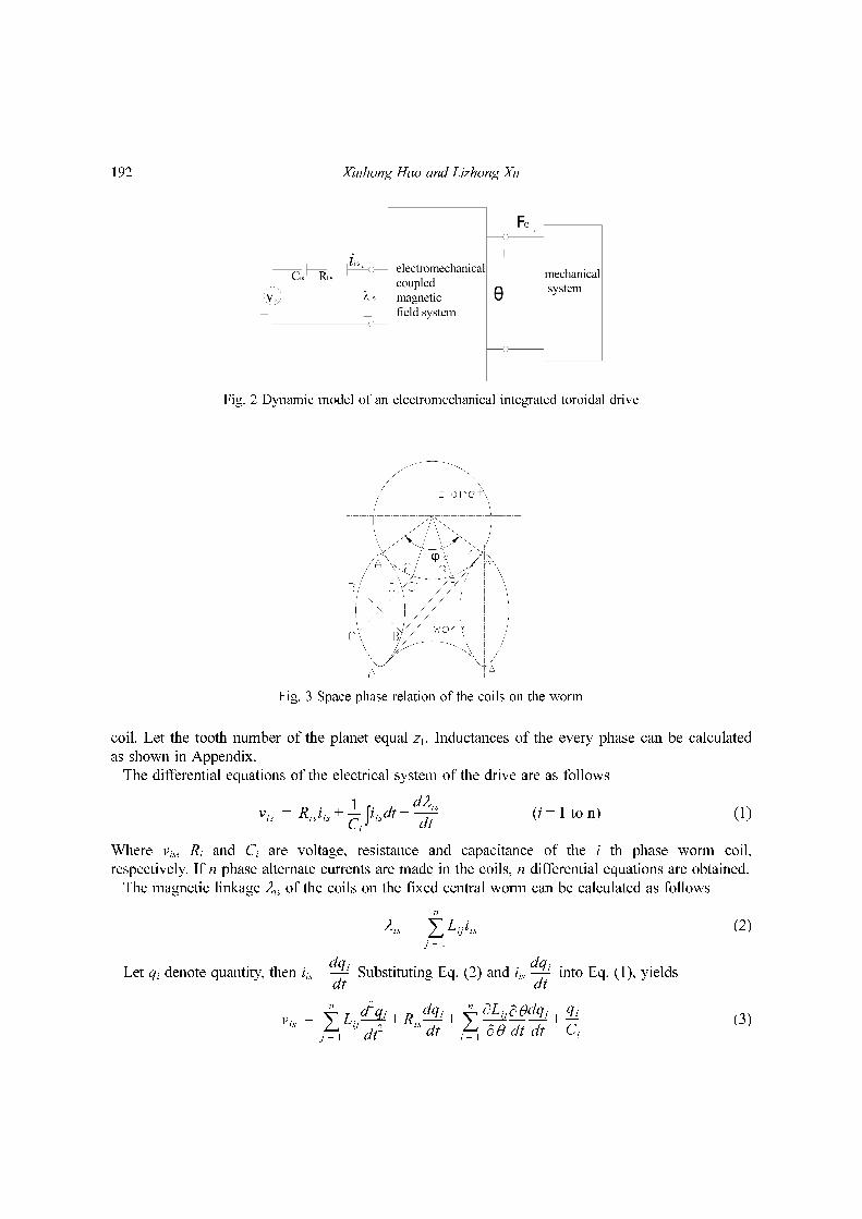
The electromechanical coupled dynamic model of an electromechanical integrated toroidal drive is
shown in Fig. 2. Space phase relation of the coils on the worm is shown in Fig. 3. Symbol φv
denotes face width angle of the worm. Then, in the transverse plane of the planet, the phase angle
of the phase-i is
(i = 1 to n)
Where n-phase number of the worm coils (n = 3)
p-the number of the pole-pairs
Let position angle θ = 0 of the planet when tooth of the planet is aligned completely with phase-1
φii 1–
n----------
φv
p-----=
192 Xiuhong Hao and Lizhong Xu
coil. Let the tooth number of the planet equal z1. Inductances of the every phase can be calculated
as shown in Appendix.
The differential equations of the electrical system of the drive are as follows
(i = 1 to n) (1)
Where vis, Ri and Ci are voltage, resistance and capacitance of the i th phase worm coil,
respectively. If n phase alternate currents are made in the coils, n differential equations are obtained.
The magnetic linkage λis of the coils on the fixed central worm can be calculated as follows
(2)
Let qi denote quantity, then iis = Substituting Eq. (2) and iis into Eq. (1), yields
(3)
vis Risiis1
Ci
----- iis td∫dλis
dt---------+ +=
λis Lijiisj 1=
n
∑=
dqi
dt-------
dqi
dt-------
vis Lijd2qj
dt2
---------j 1=
n
∑ Ris
dqi
dt-------
∂Li j
∂θ---------
∂θ
dt------
dqj
dt-------
j 1=
n
∑qi
Ci
-----+ + +=
Fig. 2 Dynamic model of an electromechanical integrated toroidal drive
Fig. 3 Space phase relation of the coils on the worm

Dynamics of electric system for electromechanical integrated toroidal drive under mechanical disturbance 193
Hence, the differential equations of the electric system for the drive can be given in matrix form as
Lv + Rv + Cv = vs (4)
The quality and voltage vectors, q and vs, and equivalent inductance, resistance and capacitance
matrices, Lv, Rv and Cv, are given in Appendix.
In Eq. (4), is rotational speed of the relative vibration between planet and worm, and it shows
influence of the mechanical system to electric system.
The equations of motion of the mechanical system for the drive are given in matrix form as
M + C + KX = F (5)
Where X and F are displacement and load vectors, respectively; M, K and C are mass, stiffness and
damping matrixes, respectively.
In Eq. (5), stiffness matrix K includes electromagnetic meshing stiffness and shows influence of
the electric system to mechanical system.
Therefore, Combining Eq. (4) with Eq. (5), the electromechanical coupled dynamic equations of
the drive system are obtained. In this paper, dynamics of the electric system for the drive under
mechanical disturbance is developed.
2. Free vibration of the electric system under mechanical disturbance
The Eq. (4) decides a team of equations which are coupled to each other. For simplicity purposes,
the formulation (4) should be transmitted into equations independent on each other. Then, Eq. (4) is
changed into the following form
LvN N + RvN N + CvN qN = vsN (6)
Where LvN, RvN and CvN are regular diagonal equivalent inductance, resistance and capacitance
matrices, respectively. vsN and qN are transmitted equivalent exciting voltage and quality vectors,
respectively (see Appendix).
Thus, Eq. (6) includes n equations independent on each other. The i th equation can be expressed
as below
ai Ni + bi Ni + ci qNi = vNi (i = 1 to n) (7)
Where ai = 1, bi = (Ri + ε Li ωm cos ωmt), ci = .
In Eq. (7), bi changes along with time t. So this is a variable coefficient differential equation. For
Eq. (7), following transformation is done
(8)
Hence, Eq. (7) is changed as below
(9)
q·· q· q
∂θ
dt------
X··
X·
q·· q·
q·· q·
ω i
2
qi xe
1
2---–
bit( )
ai
----------- td∫=
x·· α t( )x+ v′=

194 Xiuhong Hao and Lizhong Xu
Where
Changes of the angle θ between planet and worm for the mechanical system are as below
θ = θ0 + ∆θ sin (ωmt) (10)
Where θ0 is static relative rotating angle between planet and worm, ∆θ is magnitude of the dynamic
rotating displacement, ωm is frequency of the angular vibration between planet and worm.
Eq. (10) are substituted into above equations Eq. (9)and then Eq. (9) can be transformed into
following form
(11)
From analysis, it is known that ε1 and ε2 are much smaller than ε3. So ε1 and ε2 can be neglected.
And Eq. (11) is simplified as (here ε = ε3)
(12)
As only free vibration of the electric system under mechanical disturbance is discussed, let
in Eq. (12), then
(13)
Let
(14)
and
(15)
Let τ = ωt, and substituting Eqs. (14) and (15) into Eq. (13), and then let sum of the coefficients
with the same order power of the parameter ε equal zero, following equations can be given
(16a)
(16b)
(16c)
Where , and is the second order derivative of the variable xi to new variable .
Here, initial conditions are
α t( )ci
ai
---- 1
4---
bi
2t( )
ai
2------------–
1
2---
d
dt-----
bi t( )ai
-----------– v′ vNie
bit( )
2ai
----------- td∫=,=
x·· δ 1 ε1 2ωmtcos ε2 ωmtcos ε3 ωmtsin+ + +( )x+ v′=
x·· δ+ 1 ε ωmtsin+( )x v′=
v′ 0=
x·· δ+ 1 ε ωmtsin+( )x 0=
x x0 ε x1 ε2x2
……+ + +=
ω2
δ 1 ε σ1 ε2σ2
……+ + +( )=
x··0 x0+ 0=
x··1 x1+ x0 eτ σ1x··0–sin=
x··2 x2+ x1 eτ σ1x··1– σ2x
··0–sin=
eωm
ω-------= x··1 τ ω t=
x0 0( ) A= x·0 0( ) 0=
x1 0( ) 0= x·1 0( ) 0=
x2 0( ) 0= x·2 0( ) 0=
…… ⎩⎪⎪⎨⎪⎪⎧
Dynamics of electric system for electromechanical integrated toroidal drive under mechanical disturbance 195
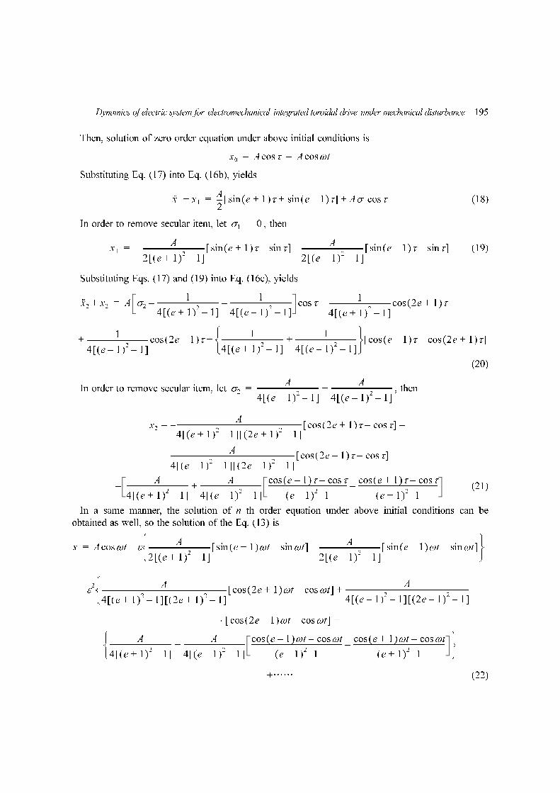
Then, solution of zero order equation under above initial conditions is
Substituting Eq. (17) into Eq. (16b), yields
(18)
In order to remove secular item, let , then
(19)
Substituting Eqs. (17) and (19) into Eq. (16c), yields
(20)
In order to remove secular item, let , then
(21)
In a same manner, the solution of n th order equation under above initial conditions can be
obtained as well, so the solution of the Eq. (13) is
+…… (22)
x0 A τcos A ω tcos= =
x··1 x1+A
2--- e 1+( )τsin e 1–( )τsin+[ ] Aσ1 τcos+=
σ1 0=
x1
A
2 e 1+( )2 1–[ ]------------------------------------ e 1+( )τsin τsin–[ ]–
A
2 e 1+( )2 1–[ ]------------------------------------ e 1–( )τsin τsin–[ ]–=
x··2 x2+ A σ2
1
4 e 1+( )2 1–[ ]------------------------------------–
1
4 e 1–( )2 1–[ ]-----------------------------------– τcos
1
4 e 1+( )2 1–[ ]------------------------------------ 2e 1+( )τcos+=
1
4 e 1–( )2 1–[ ]----------------------------------- 2e 1–( )τcos
1
4 e 1+( )2 1–[ ]------------------------------------
1
4 e 1–( )2 1–[ ]-----------------------------------+
⎩ ⎭⎨ ⎬⎧ ⎫
e 1–( )τcos 2e 1+( )τcos–[ ]+ +
σ2
A
4 e 1+( )2 1–[ ]------------------------------------
A
4 e 1–( )2 1–[ ]-----------------------------------+=
x2
A
4 e 1+( )2 1–[ ] 2e 1+( )2 1–[ ]------------------------------------------------------------------------–= 2e 1+( )τ τcos–cos[ ] –
A
4 e 1–( )2 1–[ ] 2e 1–( )2 1–[ ]------------------------------------------------------------------------ 2e 1–( )τ τcos–cos[ ]
A
4 e 1+( )2 1–[ ]------------------------------------
A
4 e 1–( )2 1–[ ]-----------------------------------+
e 1–( )τ τcos–cos
e 1–( )2 1–----------------------------------------------
e 1+( )τ τcos–cos
e 1+( )2 1–----------------------------------------------––
x A ω tcos εA
2 e 1+( )2 1–[ ]------------------------------------ e 1+( )ω tsin ω tsin–[ ] A
2 e 1–( )2 1–[ ]----------------------------------- e 1–( )ω tsin ω tsin–[ ]–
⎩ ⎭⎨ ⎬⎧ ⎫
–=
ε2 A
4 e 1+( )2 1–[ ] 2e 1+( )2 1–[ ]------------------------------------------------------------------------ 2e 1+( )cos ω t ωcos t–[ ]
A
4 e 1–( )2 1–[ ] 2e 1–( )2 1–[ ]------------------------------------------------------------------------+
⎩⎨⎧
–
2e 1–( )cos ω t ωcos t–[ ]⋅ +
A
4 e 1+( )2 1–[ ]------------------------------------
A
4 e 1–( )2 1–[ ]-----------------------------------+
e 1–( )ω t ω tcos–cos
e 1–( )2 1–-----------------------------------------------------
e 1+( )ω t ω tcos–cos
e 1+( )2 1–-----------------------------------------------------–
⎩ ⎭⎨ ⎬⎧ ⎫

196 Xiuhong Hao and Lizhong Xu
From Eq. (15), natural frequency of the electric system can be given as well
(23)
Substituting Eq. (22) into Eq. (8), and then using equation q = AN qN, the free quality vibration qi
can be given.
3. Forced response of the electric system to voltage excitation under mechanical
disturbance
In order to analyze forced responses of the electric system to electric excitation under mechanical
disturbance, expressing Eq. (7) as following form
(24)
Where voltage excitation is given as , ωe is exciting frequency of the voltage,
Let v0 is magnitude of the exciting voltage.
(25)
Substituting Eq. (24) into Eq. (23), and then let sum of the coefficients with the same order power
of the parameter equal zero, following equations can be given
(26)
In a same manner as solving Eq. (16), the solutions of the Eq. (26) can be obtained as well, and
then substituting the solutions into Eq. (25), and then using equation q = AN qN, forced vibration
quality qi can be obtained.
4. Results and discussions
4.1 Free vibrations under mechanical disturbance
Eqs. (8) and (21) are used for free vibration analysis of the electric system for the drive under
mechanical disturbance. Parameters of the numerical example are shown in Table 1. Free vibrations
ω2
δ 1ε2A
4 e 1+( )2 1–[ ]------------------------------------
ε2A
4 e 1–( )2 1–[ ]----------------------------------- ……+ + +
⎩ ⎭⎨ ⎬⎧ ⎫
=
q··Ni Ri εLiωm ωmtcos+( )q·Ni ω i
2qNi+ + vNi=
vNi ε v0 ωeti 1–
3----------+⎝ ⎠
⎛ ⎞sin=
qi q0 εqi ε2q2
……+ + +=
q··0 Riq·0 ω i
2q0+ + 0=
q··1 Riq·1 ω i
2q1+ + Liωm ωmtq· 0cos v0 ωet
i 1–
3----------π+⎝ ⎠
⎛ ⎞sin+=
q··2 Riq·2 ω i
2q2+ + Liωm ωmtq· 1cos=
……⎩⎪⎪⎪⎨⎪⎪⎪⎧

Dynamics of electric system for electromechanical integrated toroidal drive under mechanical disturbance 197
are shown in Fig. 4. Here, initial quality A is 8.0 × 10⁻⁹ C. Free vibration analysis without
mechanical disturbance shows that natural frequencies of above electric system are ω1 = 0.10869 ×10⁷ rad/s, ω2 = 0.4135 × 10⁷ rad/s and ω3 = 4.1430 × 10⁷ rad/s. Fig. 4 shows results under condition
that mechanical disturbing frequency is far from natural frequencies of the electric system (here
ωm = 1 × 10⁷ rad/s). Fig. 4(a) shows results of the first mode (ω1 = 0.10869 × 10⁷ rad/s); Fig. 4(b)
shows results of the second mode (ω2 = 0.4135 × 10⁷ rad/s); and Fig. 4(c) shows results of the third
mode (ω3 = 4.1430 × 10⁷ rad/s). Fig. 4(d) shows results without mechanical disturbance. Fig. 5
shows results under condition that the mechanical disturbing frequency is near to the natural
frequencies of the electric system. Fig. 5(a) shows results under condition that the mechanical
disturbing frequency is near to the first natural frequency of the electric system; Fig.
5(b) shows results under condition that the mechanical disturbing frequency is near to the double of
the first natural frequency of the electric system. Fig. 5(c) shows results under
condition that the mechanical disturbing frequency is near to the second natural frequency
of the electric system; Fig. 5(d) shows results under condition that the mechanical
ωm ω1≈( )
ωm 2ω1≈( )
ωm ω2≈( )
Table 1 Parameters of the example system
φv (0) ∆θ (rae) ωm (rad/s) rad p n L0 (H) L1 (H) Ci (F) Ri (Ω) ε
80 0.007 1071 3 10−3 10−3 1.6 × 10⁻¹⁰
10 0.01
Fig. 4 Free vibrations of the electric system under mechanical disturbance

198 Xiuhong Hao and Lizhong Xu
disturbing frequency is near to the double of the second natural frequency of the
electric system. Fig. 5(e) shows resulst under condition that the mechanical disturbing frequency is
near to the third natural frequency of the electric system; Fig. 5(f) shows results under
condition that the mechanical disturbing frequency is near to the double of the third natural
frequency of the electric system. From Figs.4 and 5, ones know:
(1) As time grows, vibration quality of the electric system decreases gradually. The vibration of
the quality is periodical damped wave. Magnitude of the wave is decided by initial excitation and
time. The decaying speed is decided by damping term Ri.
ωm 2ω2≈( )
ωm ω3≈( )
ωm 2ω3≈( )
Fig. 5 Resonance vibrations of the electric system under mechanical disturbance

Dynamics of electric system for electromechanical integrated toroidal drive under mechanical disturbance 199
(2) For higher natural frequency of the system, periodic time of the quality vibration is shorter. So
for the natural frequency 4.1430 × 10⁷ rad/s, the shortest periodic time of the quality vibration
occurs. It is because the periodic time of the quality vibration for the electric system is decided by
natural frequency of the electric system and disturbing frequency of the mechanical system.
(3) For the system without mechanical disturbance, the periodic time of the quality vibration is
longest. The periodic time of the quality vibration is only decided by natural frequency of the
electric system.
(4) For the system with mechanical disturbance, as time grows, small exciting wave still exists
when the wave magnitude is tending to zero. This is unfavorable to electric system.
(5) When mechanical disturbing frequency is near to the natural frequencies of the electric system
or their integer multiple, resonance vibrations occur in the electric system.
(6) The resonance vibrations are more obvious under condition that disturbing frequency is near to
the natural frequencies of the electric system than those under condition that disturbing frequency is
near to the integer multiple of the natural frequencies of the electric system.
Fig. 6 Forced responses of the electric system to voltage excitation under mechanical disturbance
Table 2 Changes of the resonance vibrations along with disturbance and excitation frequency
ωm ωe resonance vibration from disturbance coupled resonance vibration from disturbance and excitation
ωm = 2ω1 far from ωi (i = 1, 2 and 3) occur for the first mode do not occur
ωe = ω1 do not occur occur for the first mode
ωe = ω2 occur for the first mode occur for the second mode
ωe = ω3 occur for the first mode occur for the third mode
ωm = 2ω2 far from ω1 (i = 1, 2 and 3) occur for the first and second modes do not occur
ωe = ω1 occur for the first mode occur for the second mode
ωe = ω2 do not occur occur for the second mode
ωe = ω3 occur for the second mode occur for the third mode
ωm = 2ω3 far from ωi (i = 1, 2 and 3) occur for the first and third modes do not occur
ωe = ω1 occur for the third mode occur for the first mode
ωe = ω2 occur for the third mode occur for the second mode
ωe = ω3 do not occur occur for the third mode
200 Xiuhong Hao and Lizhong Xu
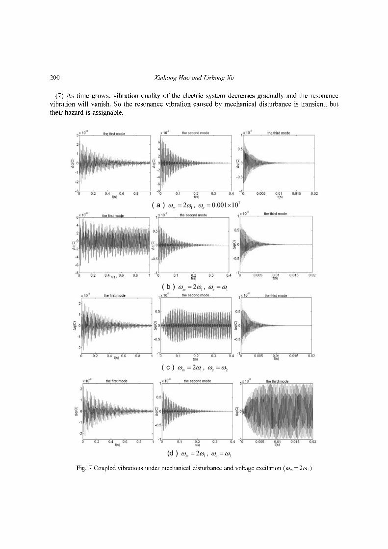
(7) As time grows, vibration quality of the electric system decreases gradually and the resonance
vibration will vanish. So the resonance vibration caused by mechanical disturbance is transient, but
their hazard is assignable.
Fig. 7 Coupled vibrations under mechanical disturbance and voltage excitation (ωm = 2ω1)

Dynamics of electric system for electromechanical integrated toroidal drive under mechanical disturbance 201
4.2 Forced responses to electric excitation under mechanical disturbance
Eqs. (26), (27) and (24) are used for forced response analysis of the electric system to voltage
excitation under mechanical disturbance. The forced responses are shown in Fig. 6. Fig. 6(a) shows
Fig. 8 Coupled vibrations under mechanical disturbance and voltage excitation (ωm = 2ω2)

202 Xiuhong Hao and Lizhong Xu
results under condition that exciting frequency is near to the first natural frequency ; Fig.
6(b) shows results under condition that exciting frequency is near to the second natural frequency
; Fig. 6(c) shows results under condition that exciting frequency is near to the third
natural frequency . Here, only results of the first mode (ω1 = 0.10869 × 10⁷ rad/s) are
presented. From Fig. 6, ones know:
ωe ω1≈( )
ωe ω2≈( )ωe ω3≈( )
Fig. 9 Coupled vibrations under mechanical disturbance and voltage excitation (ωm = 2ω3)
Dynamics of electric system for electromechanical integrated toroidal drive under mechanical disturbance 203
(1) When voltage exciting frequency ωe is near to one of the natural frequencies for the electric
system, the resonance occurs in the electric system.
(2) As the time grows, the resonance vibration caused by voltage excitation still exist which is
different from ones caused by mechanical disturbance.
(3) The forced responses of the electric system to voltage excitation under mechanical disturbance
are compound vibrations which are decided by voltage excitation, mechanical disturbance and
natural frequency of the electric system.
(4) As vibrations caused by voltage excitation exist, the vibrations caused by mechanical
disturbance are enlarged.
Under condition that voltage exciting frequency is near to the natural frequencies and the
mechanical disturbing frequency ωm is near to one-half of them for the electric system, the coupled
resonance occurs in the electric system as shown in Figs. 7-9. From Figs. 7-9, ones know: Under
the mechanical disturbance and the voltage excitation, the resonance vibration from mechanical
disturbance and the coupled resonance vibration from mechanical disturbance and voltage excitation
may occur. Changes of the two types of the resonance vibration along with disturbance frequency
and the excitation frequency are summarized in Table 2. The coupled resonance vibrations are much
larger than those caused only by mechanical disturbance or voltage excitation and they are more
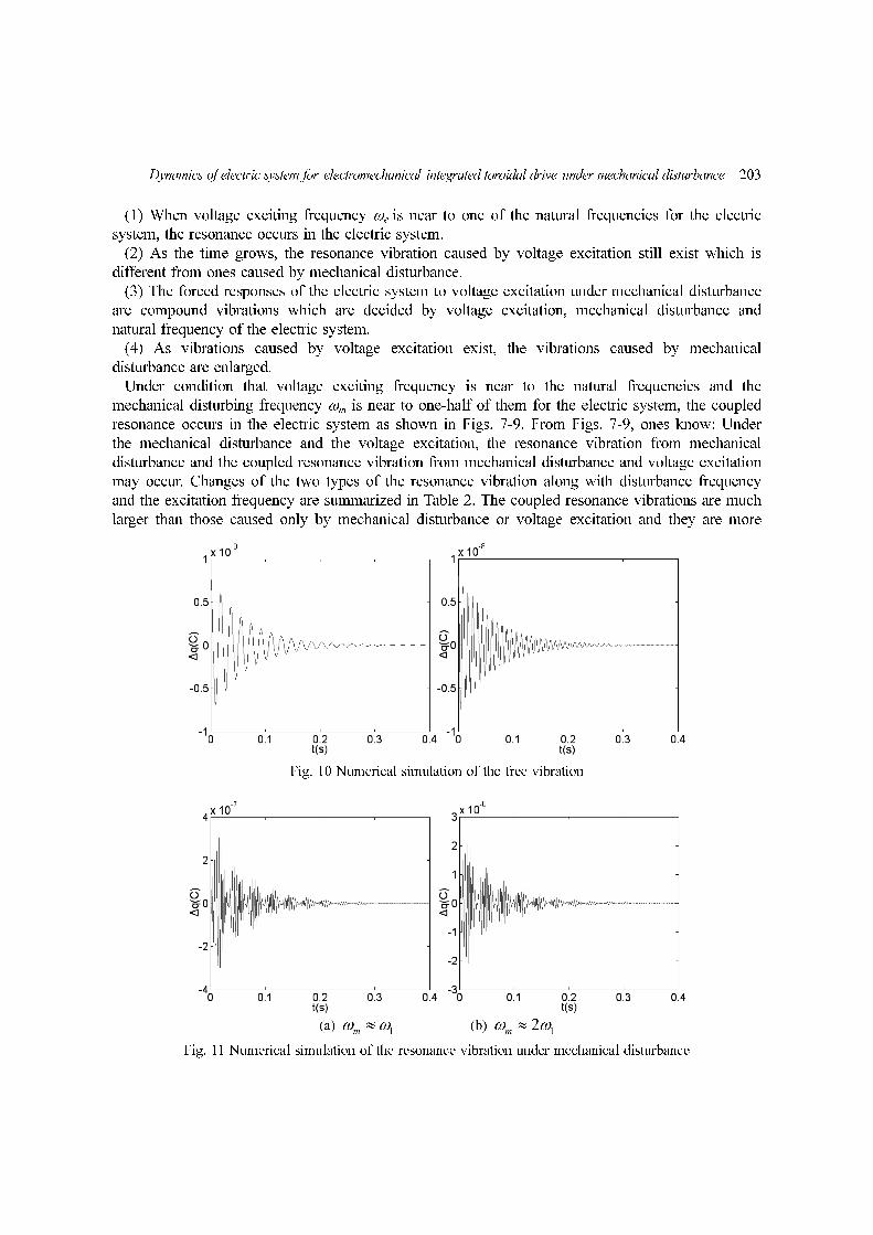
Fig. 10 Numerical simulation of the free vibration
Fig. 11 Numerical simulation of the resonance vibration under mechanical disturbance

204 Xiuhong Hao and Lizhong Xu
unfavorable to electric system.
To illustrate validity of the theoretical model, the calculating results are compared with numerical
simulation. Fig. 10 gives free vibrations done by numerical simulation. Fig. 11 gives forced
vibrations done by numerical simulation. They are done from four order Runge-Kutta method. Fig.
10(a) and (b) corresponds to Fig. 4(a) and (b), respectively. Fig. 11(a) and (b) corresponds to Fig.
5(a) and (b), respectively. These figures shows that the analytical solutions are in good agreement
with the numerical simulation.
These figures also show that the accuracy of the 3rd solution is high enough. For the free
vibration analysis, the relative error of the amplitude is smaller than 3.5%. For the forced vibration
analysis, the relative error of the amplitude is smaller than 5%.
5. Conclusions
In this paper, the electromechanical coupled dynamic equations for the drive are developed. And
the dynamics of the electric system for the drive under mechanical disturbance is discussed. Using
method of perturbation, free vibrations and forced responses of the electric system to voltage
excitation under mechanical disturbance are researched. It is known that for the system with
mechanical disturbance, as time grows, small exciting wave still exists when the wave magnitude is
tending to zero which is unfavorable to electric system. When mechanical disturbing frequency is
near to the natural frequencies of the electric system or their integer multiple, resonance vibrations
occur in the electric system. The forced responses of the electric system to voltage excitation under
mechanical disturbance are compound vibrations caused by voltage excitation, mechanical disturbance
and parameters of the system. As the time grows, the resonance vibration caused by voltage
excitation still exists and the vibrations caused by mechanical disturbance are enlarged as well. The
coupled resonance vibration caused by mechanical disturbance and voltage excitation is discussed as
well. The conditions under which above coupled resonance vibrations occur are presented. The
coupled resonance is more unfavorable to electric system and must be avoided in design.
Acknowledgments
This project is supported by National Natural Science Foundation of China.
References
Barth, O. (2000), “Harmonic piezodrive-miniaturized servo motor”, Mechatronics., 10, 545-554.Delin, Z. and Huamin, L. (1993), “Side surface harmonic stepper motor”, J. Mech. Eng., 29, 96-98.Kanaan, Hadi Youssef (2003), “Al-Haddad Kamal. Analysis of the electromechanical vibrations in induction
motor drives due to the imperfections of the mechanical transmission system”, Math Comput Simulation,63(17), 421-433.
Kuehnle, M. R. (1996), Toroidgetriebe.Urkunde uber die Erteilung des, deutschen Patent No. 1301682.Kuehnle, M. R., Peeken, H., Troeder, H. and Cerniak, S. (1981), “The Toroidal drive”, Mech Eng., 32, 32-39.Li, Zhaojun, Cai, Ganwei and Huang, Qibo (2006), “The parametric coupled vibration of the motor-elastic link
mechanism system”, J. Vib. Eng., 19(1), 93-97.
Dynamics of electric system for electromechanical integrated toroidal drive under mechanical disturbance 205
Lin Yu-Chih and Ma Chien-Ching (2008), “Resonant vibration of piezoceramic plates in fluid”, Interact.Multiscale Mech., 1(2), 177-190.
Peeken, H., Troeder, Chr. and Tooten, K. H. (1984), “Berechnung und Messung der Lastverteilung imToroidgeriebe”, Konstruktion., l36, 81-86.
Qiu, Jiajun (1989), “Torsional vibration and electric oscillation of the starting AC motor”, J. Appl. Mech., 6(4),12-19.
Shatout, A. (1996), “Reclosing torque of large induction motors with stator trapped flux”, T. Energy Conversion.,11(1), 84-90.
Tooten, K. H. (1983), Konstruktive Optimierungen an einem Umlaufradergetriebe, Diss, RWTH Aachen.Tooten, K. H. (1985), “Optimierung des Kraftubertragungsverhaltens in Getrieben mitWalzkon-takten”,
Antriebstechnik., 24, 49-55Xiong, Wanli, Duan, Zhishan and Wen, Bangchun (2001), “Characteristics of electromechanical coupling self-
synchronization of a multimotor vibration transmission system”, Chinese J. Mech. Eng., 14(3), 275-278.Xu, Lizhong (2004), “Efficiency for Toroidal drive”, Proceedings of the 11th World Congress in Mechanism and
Machine Science., Tianjin, China, April 1-4, 737-740.Xu, Lizhong and Huang, Zhen (2003), “Contact Stresses for Toroidal drive”, J. Mech. Design, 125(3), 165-168.

206 Xiuhong Hao and Lizhong Xu
Appendix
Self-inductances:
(i = 1 to n)
mutual-inductances between adjacent phases:
(i = 2 to n)
mutual-inductances between two spacing phases:
(i = 3 to n)
Where (i = 1 to n)
q = q1, ……, qi, ……, qn)T, vs = v1s, ……, vis, ……, vns)
T
Li i L0 L1 z1θ i 1–( )φv
pn------–⎝ ⎠
⎛ ⎞cos+=
Li 1 i,– L01 L1 z1θ 2i 3–( )φv
2pn---------–⎝ ⎠
⎛ ⎞cos+=
Li 2 i,– L02 L1 z1θ 2i 4–( )φv
2pn---------–⎝ ⎠
⎛ ⎞cos+=
L0 i L0
iφv
pn-------cos=
Lv
L11 L12… L1n
L21 L22… L2n
………
Ln1 Ln2… Lnn
= Rv Diag R1 R2 … Rn[ ]=dθ
dt------
l11 l12 … l1n
l21 l22 … l2n
………
ln1 ln2 … lnn
+,… … … … … …
Cv Diag1
C1
------ 1
C2
------ … 1
Cn
------=
LvN AN
TLvAN 1 I RvN AN
TRvAN RN
= =,= = =
…
…
…
…
CvN AN
TCvAN CN
λ1
λn
ω1
2
ωn
2
= = = =
……
…
… …
Dynamics of electric system for electromechanical integrated toroidal drive under mechanical disturbance 207
Here AN is regular mode matrix of Eq. (4)
vsN AN
1–vs
AN1
1( )AN2
1( ) … ANn
1( )
AN1
2( )AN2
2( ) … ANn
2( )
… … … …
AN1
n( )AN2
n( ) … ANn
n( )
1– v1
v2
v n 1–( )
vns⎩ ⎭⎪ ⎪⎪ ⎪⎪ ⎪⎨ ⎬⎪ ⎪⎪ ⎪⎪ ⎪⎧ ⎫
= =…
qN AN
1–q
AN1
1( )AN2
1( ) … ANn
1( )
AN1
2( )AN2
2( ) … ANn
2( )
… … … …
AN1
n( )AN2
n( ) … ANn
n( )
1– q1s
q2s
q n 1–( )s
qn⎩ ⎭⎪ ⎪⎪ ⎪⎪ ⎪⎨ ⎬⎪ ⎪⎪ ⎪⎪ ⎪⎧ ⎫
= =…