Dynamics Displayed by Energetic C Bombardment of Metal Overlayers
8
Dynamics Displayed by Energetic C 60 Bombardment of Metal Overlayers on an Organic Substrate Paul E. Kennedy, † Zbigniew Postawa, ‡ and Barbara J. Garrison* ,† † Department of Chemistry, 104 Chemistry Building, Pennsylvania State University, University Park, Pennsylvania 16802, United States ‡ Smoluchowski Institute of Physics, Jagiellonian University, ul. Reymonta 4, 30-059 Krakó w, Poland * S Supporting Information ABSTRACT: Cluster bombardments of 15 keV C 60 on metal−organic interfaces composed of silver atoms and octatetraene molecules were modeled using molecular dynamics computer simulations. Dynamics revealed by the simulations include the formation of holes in the metal overlayers from which underlying organic molecules are sputtered predominantly by a rapid jetlike motion and the implantation of metal atoms and clusters in the underlying organic solid. Both of these processes negatively affect the information depth for cluster bombardment of metal−organic interfaces; therefore, the simulations presented here give a clear picture of the issues associated with depth profiling through metal−organic interfaces. T hree-dimensional characterizations of materials with depth resolutions down to the nanometer level can be obtained using time-of-flight secondary ion mass spectrometry (TOF- SIMS). Depth profiles can be produced by continuously bombarding the surface with cluster ions so that successive layers of the material are removed and analyzed by the TOF- SIMS instrument. Due to dynamic and chemical effects of the cluster ions’ interaction with the surface, not all materials are easily or successfully depth profiled. 1−4 Samples that contain metal−organic interfaces are one type of material that has been shown to be particularly problematic. 2 Metal layers are important components in organic electronic devices. The most prominent example is the metal cathode in organic light- emitting diodes (OLED). 5 However, metal layers have also been applied in developing organic bistable devices for rewritable memory cells, 6,7 and in the construction of metal− organic microcavities, 8 which could be used to develop electrically driven organic solid-state lasers. The difficulty of depth profiling through metal−organic interfaces was shown by Cheng and Winograd for depth profiles of both aluminum overlayers on a peptide-doped trehalose film and Ag overlayers on a pure trehalose film using a C 60 + ion beam. 2 In the depth profiles, the secondary ion signal for the metal species was shown to persist well below the metal−organic interface. The observed effects on the depth profiles were attributed to the possible mixing and chemical damage resulting from ion cluster bombardment. Recently, TOF-SIMS has been used successfully to depth profile through OLED type devices using large gas cluster ion beams with the caveat of having first removed the outer metal cathode or that the construction of the device did not include a metal cathode. 4,9,10 The necessity to remove the metal cathode is added evidence suggesting that there are complications when depth profiling through the metal−organic interfaces. Understanding the microscopic origin of these difficulties and finding practical solutions are, therefore, important. Molecular dynamics (MD) simulations have been instru- mental in developing our current understanding of the mesoscopic processes that occur during cluster bombardment of both inorganic and organic solids. 11−22 Therefore, their application to the study of cluster bombardment of metal− organic interfaces is natural and should enable elucidation of the reasons for the difficulties of depth profiling through such systems. Recently, MD simulations performed by Restrepo et al. have been used to explain the enhanced sputtering yields observed in SIMS experiments on organic surfaces coated with metallic nanoparticles, a technique referred to as metal-assisted SIMS (MetA-SIMS). 23−25 The systems that the authors studied were composed of ∼2.5 nm gold nanoparticles (Au-NP) deposited on top of both crystalline and amorphous poly- ethylene (PE) surfaces or embedded in the amorphous PE. These studies show the complexity and diversity of actions that occur in systems with interfaces between metallic structures composed of heavy atoms and softer and lighter organic materials. The objective of this paper is to describe the dynamics of energetic C 60 cluster bombardment of metal overlayers deposited on an organic substrate. To accomplish this goal, Received: November 19, 2012 Accepted: January 9, 2013 Published: January 9, 2013 Article pubs.acs.org/ac © 2013 American Chemical Society 2348 dx.doi.org/10.1021/ac303348y | Anal. Chem. 2013, 85, 2348−2355
Transcript of Dynamics Displayed by Energetic C Bombardment of Metal Overlayers
Dynamics Displayed by Energetic C60 Bombardment of MetalOverlayers on an Organic SubstratePaul E. Kennedy,† Zbigniew Postawa,‡ and Barbara J. Garrison*,†
†Department of Chemistry, 104 Chemistry Building, Pennsylvania State University, University Park, Pennsylvania 16802, UnitedStates‡Smoluchowski Institute of Physics, Jagiellonian University, ul. Reymonta 4, 30-059 Krakow, Poland
*S Supporting Information
ABSTRACT: Cluster bombardments of 15 keV C60 on metal−organicinterfaces composed of silver atoms and octatetraene molecules were modeledusing molecular dynamics computer simulations. Dynamics revealed by thesimulations include the formation of holes in the metal overlayers from whichunderlying organic molecules are sputtered predominantly by a rapid jetlikemotion and the implantation of metal atoms and clusters in the underlyingorganic solid. Both of these processes negatively affect the information depthfor cluster bombardment of metal−organic interfaces; therefore, thesimulations presented here give a clear picture of the issues associated withdepth profiling through metal−organic interfaces.
Three-dimensional characterizations of materials with depthresolutions down to the nanometer level can be obtained
using time-of-flight secondary ion mass spectrometry (TOF-SIMS). Depth profiles can be produced by continuouslybombarding the surface with cluster ions so that successivelayers of the material are removed and analyzed by the TOF-SIMS instrument. Due to dynamic and chemical effects of thecluster ions’ interaction with the surface, not all materials areeasily or successfully depth profiled.1−4 Samples that containmetal−organic interfaces are one type of material that has beenshown to be particularly problematic.2 Metal layers areimportant components in organic electronic devices. Themost prominent example is the metal cathode in organic light-emitting diodes (OLED).5 However, metal layers have alsobeen applied in developing organic bistable devices forrewritable memory cells,6,7 and in the construction of metal−organic microcavities,8 which could be used to developelectrically driven organic solid-state lasers. The difficulty ofdepth profiling through metal−organic interfaces was shown byCheng and Winograd for depth profiles of both aluminumoverlayers on a peptide-doped trehalose film and Ag overlayerson a pure trehalose film using a C60
+ ion beam.2 In the depthprofiles, the secondary ion signal for the metal species wasshown to persist well below the metal−organic interface. Theobserved effects on the depth profiles were attributed to thepossible mixing and chemical damage resulting from ion clusterbombardment. Recently, TOF-SIMS has been used successfullyto depth profile through OLED type devices using large gascluster ion beams with the caveat of having first removed theouter metal cathode or that the construction of the device didnot include a metal cathode.4,9,10 The necessity to remove the
metal cathode is added evidence suggesting that there arecomplications when depth profiling through the metal−organicinterfaces. Understanding the microscopic origin of thesedifficulties and finding practical solutions are, therefore,important.Molecular dynamics (MD) simulations have been instru-
mental in developing our current understanding of themesoscopic processes that occur during cluster bombardmentof both inorganic and organic solids.11−22 Therefore, theirapplication to the study of cluster bombardment of metal−organic interfaces is natural and should enable elucidation ofthe reasons for the difficulties of depth profiling through suchsystems. Recently, MD simulations performed by Restrepo etal. have been used to explain the enhanced sputtering yieldsobserved in SIMS experiments on organic surfaces coated withmetallic nanoparticles, a technique referred to as metal-assistedSIMS (MetA-SIMS).23−25 The systems that the authors studiedwere composed of ∼2.5 nm gold nanoparticles (Au-NP)deposited on top of both crystalline and amorphous poly-ethylene (PE) surfaces or embedded in the amorphous PE.These studies show the complexity and diversity of actions thatoccur in systems with interfaces between metallic structurescomposed of heavy atoms and softer and lighter organicmaterials.The objective of this paper is to describe the dynamics of
energetic C60 cluster bombardment of metal overlayersdeposited on an organic substrate. To accomplish this goal,
Received: November 19, 2012Accepted: January 9, 2013Published: January 9, 2013
Article
pubs.acs.org/ac
© 2013 American Chemical Society 2348 dx.doi.org/10.1021/ac303348y | Anal. Chem. 2013, 85, 2348−2355
MD simulations of 15 keV C60 bombardment at normalincidence of silver (Ag) metal overlayers with a thicknessvarying from 0 nm (a bare octatetraene crystal) up to 4.7 nmon a crystalline octatetraene substrate have been performed.The results are used to provide insight into phenomena beingresponsible for the difficulties associated with depth profilingthrough metal−organic interfaces.
■ DESCRIPTION OF THE CALCULATION
Molecular dynamics simulations were employed to investigatethe dynamics of cluster bombardment of metal−organicinterfaces. Ag{111} and a trans,trans-1,3,5,7-octatetraene crystal(C8H10) were chosen for the metal overlayer and underlyingorganic solid due to previous familiarity with using thesesystems in MD simulations.19,26−28 Systems with metaloverlayers varying from 4.7 nm thickness down to the bareoctatetraene solid in roughly 0.94 nm (four atomic layers)decrements were utilized to mimic the various stages oftransition through a metal−organic interface during depthprofiling. The crystalline octatetraene solid has a monoclinicstructure with a density of 1 g/cm3,29 which is much smallerthan a density of 10.5 g/cm3 for a face-centered cubic (fcc) Agsample. There is also a significant difference in cohesiveenergies between these materials. Octatetraene and silver havecohesive energies of 0.52 and 2.95 eV, respectively. TheCrystalMaker program was used to generate the octatetraenestructure,30 which was then energy minimized. Thirty-fivelayers of Ag{111} were positioned above the organic surface,and the system was allowed to quench. The resulting systemwas then cropped into hemispheres with the appropriate radiusto confine 15 keV of the primary kinetic energy for theintended metal overlayer thickness. As a result, the radius of thehemispherical samples changed from 16.5 nm for a thickestmetal overlayer to 20.5 nm for the bare molecular crystal.Corresponding samples have from 709 011 to 1 854 312 atoms.Excluding the surface, the outer shell of the hemisphericalsystems were contained by a rigid boundary of 1.3 nm, whichwas bordered by a stochastic region with a width of 2.6 nm that
was used to prevent reflection of the pressure waves generatedby the cluster impacts.Several interatomic potentials were used to model the
relevant interactions that occur during the bombardmentprocess. The reactive AIREBO potential was used forinteractions between the hydrocarbon atoms comprising boththe molecules of the octatetraene solid and the C60 cluster.
31
The Ag−Ag interactions were described by the moleculardynamics/Monte Carlo corrected effective medium (MD/MC-CEM) potential.32 Because a potential that would describechemistry between the Ag and the organic molecules does notexist, interactions between Ag and organic atoms weredescribed using two-body Lennard-Jones (LJ) potentialssplined with Moliere potentials for the repulsive walls.33 Theparallel sputtering code implementing the message passinginterface strategy (MPI) was used to perform calculations. Thedetails of this approach can be found elsewhere.34 We used 16processors per simulation, and the elapsed time per trajectoryranged from 1 to 6 weeks. We used a variable time step fifth-order Gear predictor−corrector integrator,34 and the time stepranged from hundredths of femtoseconds, during the initialimpact of the cluster when the forces are changing most rapidly,to a little over one femtosecond at the end of the trajectory.Simulations were terminated when molecular sputtering fromthe organic solid had ceased, which usually took from 50 to 90ps. Since the goal is to understand the general dynamics of thebombardment of a metal/organic system and not to obtaindetailed quantitative results, we have calculated only onetrajectory per set of initial conditions.The simulations described here stretch the use of empirical
interaction potentials. As we have noted previously,11,34−37 ifone does not have a perfect set of interaction potentials, thenthat limits the interpretations that can be made from thecomputer simulations. Briefly, the reactive REBO potential hasbeen described quantitatively for small molecules and fragmentsby Brenner et al.38,39 The energetics and geometry of smallmolecules such as octatetraene are well-described; however, thequantitative descriptions of activation barriers for reactionsother than direct bond cleavage are not calibrated and there is
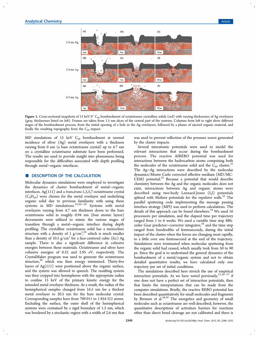
Figure 1. Cross-sectional snapshots of 15 keV 0° C60 bombardment of octatetraene crystalline solids (red) with varying thicknesses of Ag overlayers(gray, thicknesses listed on left). Frames are taken from 1.5 nm slices of the central part of the systems. Columns from left to right show differentstages of the bombardment process, from the initial opening of a hole in the Ag overlayers, followed by a plume of ejected organic material, andfinally the resulting topography from the C60 impact.
Analytical Chemistry Article
dx.doi.org/10.1021/ac303348y | Anal. Chem. 2013, 85, 2348−23552349
no reason to suspect that the reaction barriers are good. Thelong-range portion of the AIREBO potential31 has beendescribed by its authors. The binding energy of theoctatetratene crystal is experimentally unknown. The exper-imental octatetraene structure is stable using the AIREBOpotential. The interaction between the Ag surface and atomswith the organic molecules and fragments is a completeapproximation because, unfortunately, there is not a goodmany-body description for the system. The LJ potential useddescribes a weak interaction between particles. In summary,then, the system described in the simulation is a molecular solidbound weakly to a metal overlayer. The results that we candescribe well are those related to physical processes such aschanges in ejection mechanism and how the change inmechanisms changes the sputtering yield and kinetic energydistribution. There is limited ability to describe specifics ofchemical reactions. Moreover, we view this system as a genericmolecular solid with a generic metal overlayer and do notattach significance to the octatetraene and Ag chemistry.The empirical potentials generally used assume that the
system stays in the ground electronic state. Consequently, allbond cleavage reactions go to neutral species and not ionizedstates. Also, as discussed previously40 the impact of the clustercan create a very dense region in molecular solids. Thisenvironment cannot be described by a single electronic state.Thus, the initial reactions in the systems in which the clusterdeposits considerable energy in the organic material should beconsidered approximate.
■ RESULTS AND DISCUSSION
Distinctive dynamics are elucidated by MD computersimulations for the energetic cluster bombardment of systemscomposed of metal overlayers on an organic substrate ascompared to the energetic cluster impacts on systems such asinorganic solids, molecular organic solids, molecular organicoverlayers on metal substrates, and metal nanoparticlesdeposited on organic polymer substrates.11,20,25,41−48 Importantfactors responsible for these distinctive dynamics include thelarge disparity in the cohesive energy of the tightly bound metalatoms in the overlayer and the loosely bound organic moleculesof the substrate and the much greater compressibility of theorganic material compared to the metal overlayer. The resultingdynamics due to kiloelectronvolt cluster bombardment dependson the metal overlayer thickness as shown in Figure 1.The MD studies performed on single-component systems
have shown that the basic dynamics initiated by C60 impactinvolve projectile-stimulated mesoscopic motion that pushes
material hemispherically away from the impact point. Thelateral movement of relocated material is later converted intovertical fluid-like motion of atoms along the walls of theforming crater. The downward motion of material causes thematerial below the impact point to compress. This compressedmaterial eventually relaxes and causes an upward movement ofatoms to fill in the bottom of the crater.19,21,26,49,50 The finalresult of all these actions is the formation of the azimuthallyisotropic crater surrounded by the almost circular rim. Atomsor molecules with sufficient kinetic energy can escape thesurface and be ejected. MD studies identify two processesleading to particle emission. High-energy particles are emittedfrom the forming corona of the crater soon after the projectileimpact by a fluid flow type process, while low-energy particlesare ejected later from the volume of the crater by an effusive-like motion.49 Although these basic motions are also observedfor these metal−organic overlayer systems as shown in Figure1, there are also important differences. The snapshots for eachsystem of Figure 1 are taken at the moment when the metaloverlayer is penetrated by the C60 cluster (left), when a plumeof ejecting organic molecules and fragments initiates (middle),and when the final surface topography is formed (right). First,for the 3.8 nm film (Figure 1a−c and Animation 1 in theSupporting Information), the main change from the pure metalsystem is that the soft organic material allows the metal layer topush into it creating a small but temporary hole. Some of theorganic molecules expand into the hole (Figure 1b) and eject,while some ultimately adsorb to the top metal surface. In thiscase, almost all impacting energy is absorbed in the metaloverlayer (see caption to Figure 2). The trend continues for the2.8 nm film (Figure 1d−f and Animation 2 in the SupportingInformation) except that now the thickness of metal layer is notsufficient to absorb all the incident energy, integrity of the layeris compromised, a permanent hole in the overlayer is created,and chunks of metal are deposited in the organic material.Organic molecules eject through the hole, and organic materialcoats the metal surface as shown in Figure 1f. The finalconfiguration includes one large metal cluster and several metalatoms deposited in the organic layer. For the 0.9 nm film(Figure 1g−i and Animation 3 in the Supporting Information)the C60 blasts into the organic substrate depositing many metalparticles into the organic material. Much of the cluster energy isdeposited in the organic layer. If there were no overlayer, theorganic molecules would begin to flow off the surface by thefluid flow along the walls of the forming crater.28,49 The metaloverlayer, however, prevents this type of ejection. The upwardmotion of the molecules is blocked by the overhanging metal
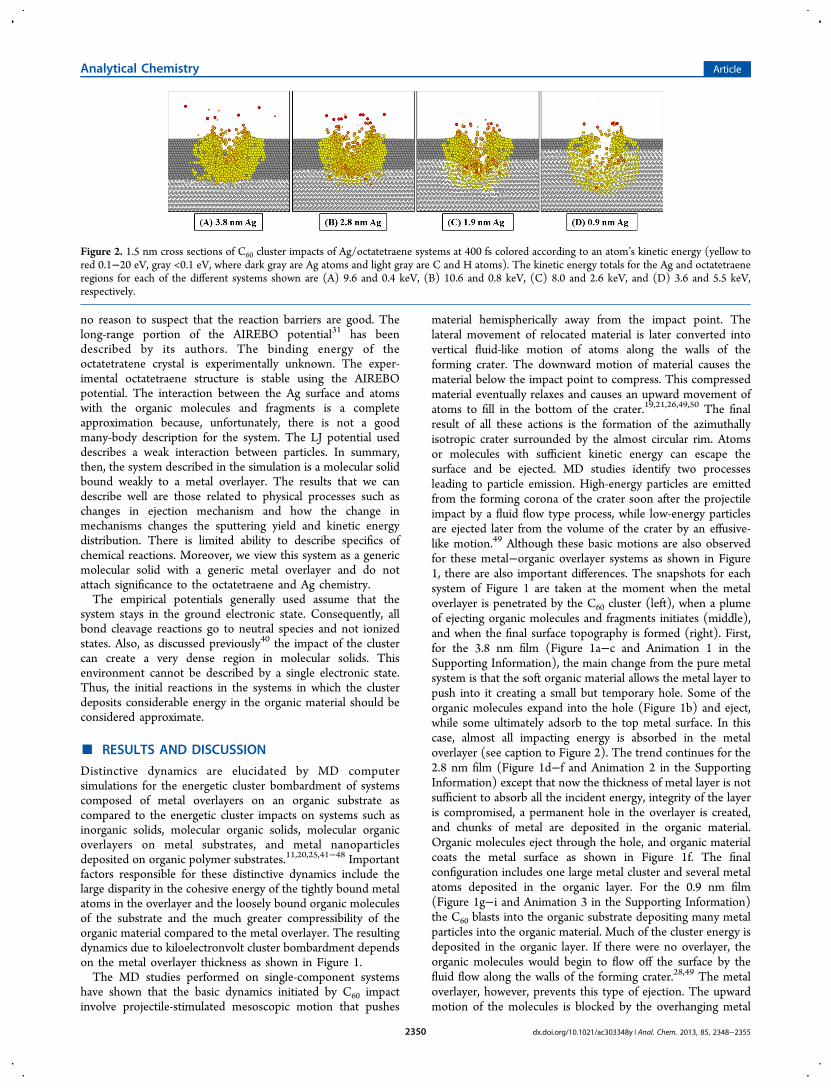
Figure 2. 1.5 nm cross sections of C60 cluster impacts of Ag/octatetraene systems at 400 fs colored according to an atom’s kinetic energy (yellow tored 0.1−20 eV, gray <0.1 eV, where dark gray are Ag atoms and light gray are C and H atoms). The kinetic energy totals for the Ag and octatetraeneregions for each of the different systems shown are (A) 9.6 and 0.4 keV, (B) 10.6 and 0.8 keV, (C) 8.0 and 2.6 keV, and (D) 3.6 and 5.5 keV,respectively.
Analytical Chemistry Article
dx.doi.org/10.1021/ac303348y | Anal. Chem. 2013, 85, 2348−23552350
layer, and the pressure exerted by the organic molecules tryingto escape puts the thin metal layer into a cantilever-type motion(see Animation 3 in the Supporting Information). Theexistence of the hard metal overlayer limits the diameter ofthe crater opening as compared to the bare organic solidmaking it more difficult for the molecules to eject. The finaltopography of the system depicted in Figure 1i is of a crater 4nm deep with the metal overlayer overhanging the crater wallsof the organic region. Even though a few metal clusters weresputtered with the upward expansion of solid, the majority ofthese clusters remain implanted in the organic region (Figure1i).Energy Deposition. How the C60 energy is deposited
illustrates the mechanisms of damage formation and sputtering.Snapshots of the kinetic energy distribution taken at 400 fs, atime when the energy has reached the interface for all layerthicknesses, are shown in Figure 2A−D. The atoms are coloredby their kinetic energies with gray atoms indicating energies lessthan 0.1 eV and atoms with from 0.1 to 20 eV of kinetic energycolored from yellow to reddish orange. Particles with greaterthan 20 eV are red. The discussion below focuses on the redatoms. The caption gives the total kinetic energy deposited inboth the metal overlayer and the organic substrate for the givensystems.The starting point for understanding the change in the
energy deposition as a function of metal layer thickness is forthe thickest layer as shown in Figure 2A. The energy that goesinto the metal substrate is distributed among many Ag atoms asthe hard metal material is relatively uncompressible. In thiscase, almost 96% of deposited energy is confined to the metaloverlayer. When the metal overlayer is thinner (Figure 2, partsB and C), the energy deposition occurs both in the metal andorganic layers. There are two consequences of this change.First, there is energy directly deposited in the organic layer thatgoes toward ejecting molecules or remains trapped in theorganic substrate leading to material mixing. Second, metalatoms move downward at the interface and are deposited in theorganic material. Solid metal samples, on the other hand,confine the energy deposition to a depth of about 4 nm; theintroduction of a metal−organic interface allows the energy aswell as metal particles to go as deep as 8 nm below the surfaceas seen in Figure 1 and discussed below. The change in themechanism of energy transfer as the metal overlayer becomesthinner affects the amount and spread of metal implantation inthe organic substrate as well as the velocities of the sputteredorganic molecules.Kinetic Energies of Sputtered Substrate Molecules. A
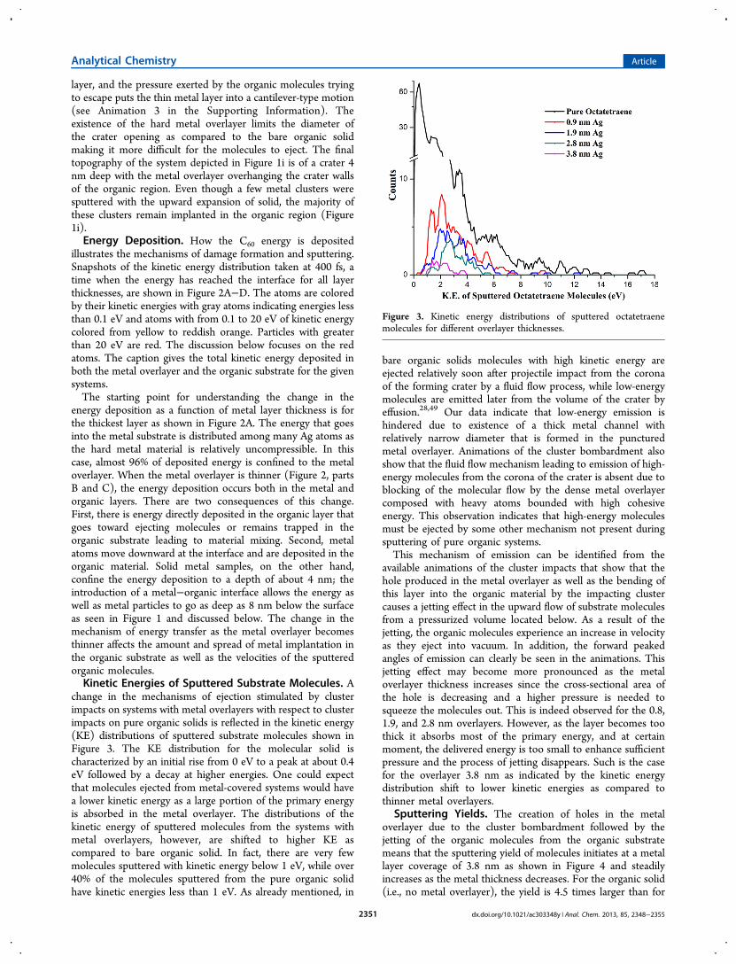
change in the mechanisms of ejection stimulated by clusterimpacts on systems with metal overlayers with respect to clusterimpacts on pure organic solids is reflected in the kinetic energy(KE) distributions of sputtered substrate molecules shown inFigure 3. The KE distribution for the molecular solid ischaracterized by an initial rise from 0 eV to a peak at about 0.4eV followed by a decay at higher energies. One could expectthat molecules ejected from metal-covered systems would havea lower kinetic energy as a large portion of the primary energyis absorbed in the metal overlayer. The distributions of thekinetic energy of sputtered molecules from the systems withmetal overlayers, however, are shifted to higher KE ascompared to bare organic solid. In fact, there are very fewmolecules sputtered with kinetic energy below 1 eV, while over40% of the molecules sputtered from the pure organic solidhave kinetic energies less than 1 eV. As already mentioned, in
bare organic solids molecules with high kinetic energy areejected relatively soon after projectile impact from the coronaof the forming crater by a fluid flow process, while low-energymolecules are emitted later from the volume of the crater byeffusion.28,49 Our data indicate that low-energy emission ishindered due to existence of a thick metal channel withrelatively narrow diameter that is formed in the puncturedmetal overlayer. Animations of the cluster bombardment alsoshow that the fluid flow mechanism leading to emission of high-energy molecules from the corona of the crater is absent due toblocking of the molecular flow by the dense metal overlayercomposed with heavy atoms bounded with high cohesiveenergy. This observation indicates that high-energy moleculesmust be ejected by some other mechanism not present duringsputtering of pure organic systems.This mechanism of emission can be identified from the
available animations of the cluster impacts that show that thehole produced in the metal overlayer as well as the bending ofthis layer into the organic material by the impacting clustercauses a jetting effect in the upward flow of substrate moleculesfrom a pressurized volume located below. As a result of thejetting, the organic molecules experience an increase in velocityas they eject into vacuum. In addition, the forward peakedangles of emission can clearly be seen in the animations. Thisjetting effect may become more pronounced as the metaloverlayer thickness increases since the cross-sectional area ofthe hole is decreasing and a higher pressure is needed tosqueeze the molecules out. This is indeed observed for the 0.8,1.9, and 2.8 nm overlayers. However, as the layer becomes toothick it absorbs most of the primary energy, and at certainmoment, the delivered energy is too small to enhance sufficientpressure and the process of jetting disappears. Such is the casefor the overlayer 3.8 nm as indicated by the kinetic energydistribution shift to lower kinetic energies as compared tothinner metal overlayers.
Sputtering Yields. The creation of holes in the metaloverlayer due to the cluster bombardment followed by thejetting of the organic molecules from the organic substratemeans that the sputtering yield of molecules initiates at a metallayer coverage of 3.8 nm as shown in Figure 4 and steadilyincreases as the metal thickness decreases. For the organic solid(i.e., no metal overlayer), the yield is 4.5 times larger than for
Figure 3. Kinetic energy distributions of sputtered octatetraenemolecules for different overlayer thicknesses.
Analytical Chemistry Article
dx.doi.org/10.1021/ac303348y | Anal. Chem. 2013, 85, 2348−23552351
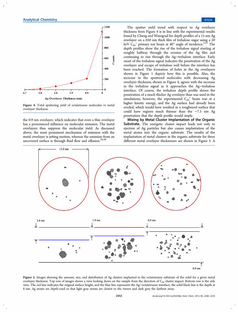
the 0.9 nm overlayer, which indicates that even a thin overlayerhas a pronounced influence on molecular emission. The metaloverlayers thus suppress the molecular yield. As discussedabove, the most prominent mechanism of emission with themetal overlayer is jetting motion, whereas the emission from anuncovered surface is through fluid flow and effusion.28,49
The sputter yield trend with respect to Ag overlayerthickness from Figure 4 is in line with the experimental resultsfound by Cheng and Winograd for depth profiles of a 15 nm Agoverlayer on a 650 nm thick film of trehalose sugar using a 20keV C60
+ primary ion beam at 40° angle of incidence.2,51 Thedepth profiles show the rise of the trehalose signal starting atroughly halfway through the erosion of the Ag film andcontinuing to rise through the Ag−trehalose interface. Earlyonset of the trehalose signal indicates the penetration of the Agoverlayer and escape of trehalose well before the interface hasbeen reached. The formation of holes in the Ag overlayersshown in Figure 1 depicts how this is possible. Also, theincrease in the sputtered molecules with decreasing Agoverlayer thickness, shown in Figure 4, agrees with the increasein the trehalose signal as it approaches the Ag−trehaloseinterface. Of course, the trehalose depth profile shows thepenetration of a much thicker Ag overlayer than was used in thesimulations; however, the experimental C60
+ beam was at ahigher kinetic energy, and the Ag surface had already beeneroded, which would have resulted in a roughened surface thatcould have regions much thinner than the ∼7.5 nm Agpenetration that the depth profile would imply.
Mixing by Metal Cluster Implantation of the OrganicSubstrate. The energetic cluster impact leads not only toejection of Ag particles but also causes implantation of themetal atoms into the organic substrate. The results of theimplantation of metal clusters in the organic substrate for threedifferent metal overlayer thicknesses are shown in Figure 5. A
Figure 4. Total sputtering yield of octatetraene molecules vs metaloverlayer thickness.
Figure 5. Images showing the amount, size, and distribution of Ag clusters implanted in the octatetraene substrate of the solid for a given metaloverlayer thickness. Top row of images shows a view looking down on the sample from the direction of C60 cluster impact. Bottom row is the sideview. The red line indicates the original surface height, and the blue line represents the Ag−octatetraene interface; the solid black line is the depth at8 nm. Ag atoms are depth-cued so that light gray atoms are closest to the viewer and dark gray the farthest away.
Analytical Chemistry Article
dx.doi.org/10.1021/ac303348y | Anal. Chem. 2013, 85, 2348−23552352
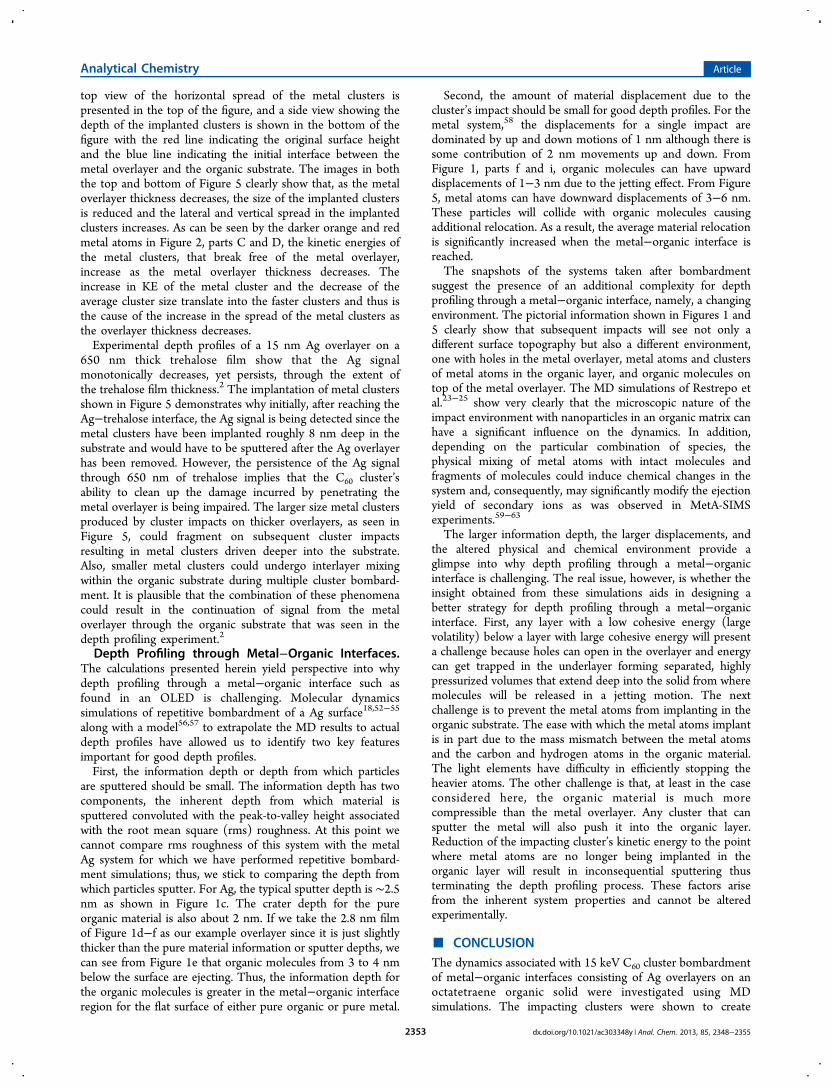
top view of the horizontal spread of the metal clusters ispresented in the top of the figure, and a side view showing thedepth of the implanted clusters is shown in the bottom of thefigure with the red line indicating the original surface heightand the blue line indicating the initial interface between themetal overlayer and the organic substrate. The images in boththe top and bottom of Figure 5 clearly show that, as the metaloverlayer thickness decreases, the size of the implanted clustersis reduced and the lateral and vertical spread in the implantedclusters increases. As can be seen by the darker orange and redmetal atoms in Figure 2, parts C and D, the kinetic energies ofthe metal clusters, that break free of the metal overlayer,increase as the metal overlayer thickness decreases. Theincrease in KE of the metal cluster and the decrease of theaverage cluster size translate into the faster clusters and thus isthe cause of the increase in the spread of the metal clusters asthe overlayer thickness decreases.Experimental depth profiles of a 15 nm Ag overlayer on a
650 nm thick trehalose film show that the Ag signalmonotonically decreases, yet persists, through the extent ofthe trehalose film thickness.2 The implantation of metal clustersshown in Figure 5 demonstrates why initially, after reaching theAg−trehalose interface, the Ag signal is being detected since themetal clusters have been implanted roughly 8 nm deep in thesubstrate and would have to be sputtered after the Ag overlayerhas been removed. However, the persistence of the Ag signalthrough 650 nm of trehalose implies that the C60 cluster’sability to clean up the damage incurred by penetrating themetal overlayer is being impaired. The larger size metal clustersproduced by cluster impacts on thicker overlayers, as seen inFigure 5, could fragment on subsequent cluster impactsresulting in metal clusters driven deeper into the substrate.Also, smaller metal clusters could undergo interlayer mixingwithin the organic substrate during multiple cluster bombard-ment. It is plausible that the combination of these phenomenacould result in the continuation of signal from the metaloverlayer through the organic substrate that was seen in thedepth profiling experiment.2
Depth Profiling through Metal−Organic Interfaces.The calculations presented herein yield perspective into whydepth profiling through a metal−organic interface such asfound in an OLED is challenging. Molecular dynamicssimulations of repetitive bombardment of a Ag surface18,52−55
along with a model56,57 to extrapolate the MD results to actualdepth profiles have allowed us to identify two key featuresimportant for good depth profiles.First, the information depth or depth from which particles
are sputtered should be small. The information depth has twocomponents, the inherent depth from which material issputtered convoluted with the peak-to-valley height associatedwith the root mean square (rms) roughness. At this point wecannot compare rms roughness of this system with the metalAg system for which we have performed repetitive bombard-ment simulations; thus, we stick to comparing the depth fromwhich particles sputter. For Ag, the typical sputter depth is ∼2.5nm as shown in Figure 1c. The crater depth for the pureorganic material is also about 2 nm. If we take the 2.8 nm filmof Figure 1d−f as our example overlayer since it is just slightlythicker than the pure material information or sputter depths, wecan see from Figure 1e that organic molecules from 3 to 4 nmbelow the surface are ejecting. Thus, the information depth forthe organic molecules is greater in the metal−organic interfaceregion for the flat surface of either pure organic or pure metal.
Second, the amount of material displacement due to thecluster’s impact should be small for good depth profiles. For themetal system,58 the displacements for a single impact aredominated by up and down motions of 1 nm although there issome contribution of 2 nm movements up and down. FromFigure 1, parts f and i, organic molecules can have upwarddisplacements of 1−3 nm due to the jetting effect. From Figure5, metal atoms can have downward displacements of 3−6 nm.These particles will collide with organic molecules causingadditional relocation. As a result, the average material relocationis significantly increased when the metal−organic interface isreached.The snapshots of the systems taken after bombardment
suggest the presence of an additional complexity for depthprofiling through a metal−organic interface, namely, a changingenvironment. The pictorial information shown in Figures 1 and5 clearly show that subsequent impacts will see not only adifferent surface topography but also a different environment,one with holes in the metal overlayer, metal atoms and clustersof metal atoms in the organic layer, and organic molecules ontop of the metal overlayer. The MD simulations of Restrepo etal.23−25 show very clearly that the microscopic nature of theimpact environment with nanoparticles in an organic matrix canhave a significant influence on the dynamics. In addition,depending on the particular combination of species, thephysical mixing of metal atoms with intact molecules andfragments of molecules could induce chemical changes in thesystem and, consequently, may significantly modify the ejectionyield of secondary ions as was observed in MetA-SIMSexperiments.59−63
The larger information depth, the larger displacements, andthe altered physical and chemical environment provide aglimpse into why depth profiling through a metal−organicinterface is challenging. The real issue, however, is whether theinsight obtained from these simulations aids in designing abetter strategy for depth profiling through a metal−organicinterface. First, any layer with a low cohesive energy (largevolatility) below a layer with large cohesive energy will presenta challenge because holes can open in the overlayer and energycan get trapped in the underlayer forming separated, highlypressurized volumes that extend deep into the solid from wheremolecules will be released in a jetting motion. The nextchallenge is to prevent the metal atoms from implanting in theorganic substrate. The ease with which the metal atoms implantis in part due to the mass mismatch between the metal atomsand the carbon and hydrogen atoms in the organic material.The light elements have difficulty in efficiently stopping theheavier atoms. The other challenge is that, at least in the caseconsidered here, the organic material is much morecompressible than the metal overlayer. Any cluster that cansputter the metal will also push it into the organic layer.Reduction of the impacting cluster’s kinetic energy to the pointwhere metal atoms are no longer being implanted in theorganic layer will result in inconsequential sputtering thusterminating the depth profiling process. These factors arisefrom the inherent system properties and cannot be alteredexperimentally.
■ CONCLUSIONThe dynamics associated with 15 keV C60 cluster bombardmentof metal−organic interfaces consisting of Ag overlayers on anoctatetraene organic solid were investigated using MDsimulations. The impacting clusters were shown to create
Analytical Chemistry Article
dx.doi.org/10.1021/ac303348y | Anal. Chem. 2013, 85, 2348−23552353
holes in the metal overlayer through which the underlyingorganic molecules can sputter in a jetting motion. For metaloverlayers thinner than 3 nm, metal atoms and clusters wereimplanted in the underlying organic solid. The largerinformation depth, the larger displacements, and the alteredphysical and chemical environment are the main reasons for thepoor ability to depth profile through a metal−organic interface.Although the simulations provide a picture of the issuesassociated with depth profiling through a metal−organicinterface, they do not provide a magic solution that will beunder the experimentalist’s control. We did perform testsimulations with other beam conditions, for instance, with Ar872clusters as the projectile. These simulations did not find a goodsolution.
■ ASSOCIATED CONTENT*S Supporting InformationAnimations as noted in the text. This material is available freeof charge via the Internet at http://pubs.acs.org.
■ AUTHOR INFORMATIONNotesThe authors declare no competing financial interest.
■ ACKNOWLEDGMENTSThe authors gratefully acknowledge financial support from theNational Science Foundation Grant No. CHE-0910564 and thePolish National Science Center Program No. PB1839/B/H02/2011/40. Computational resources were provided by theResearch Computing and Cyberinfrastructure group at PennState University.
■ REFERENCES(1) Mahoney, C. M. Mass Spectrom. Rev. 2010, 29, 247.(2) Cheng, J.; Winograd, N. Appl. Surf. Sci. 2006, 252, 6498.(3) Cramer, H. G.; Grehl, T.; Kollmer, F.; Moellers, R.; Niehuis, E.;Rading, D. Appl. Surf. Sci. 2008, 255, 966.(4) Niehuis, E. In ToF-SIMS: Surface Analysis by Mass Spectrometry,2nd ed.; Vickerman, J. C., Briggs, D., Eds.; IM Publications:Chichester, U.K., 2012.(5) Fu, H.; Cheng, Y.-M.; Chou, P.-T.; Chi, Y. Mater. Today 2011,14, 472.(6) Ma, L. P.; Liu, J.; Yang, Y. Appl. Phys. Lett. 2002, 80, 2997.(7) Chu, C. W.; Ouyang, J.; Tseng, J.-H.; Yang, Y. Adv. Mater.(Weinheim, Ger.) 2005, 17, 1440.(8) Brueckner, R.; Zakhidov, A. A.; Scholz, R.; Sudzius, M.;Hintschich, S. I.; Froeb, H.; Lyssenko, V. G.; Leo, K. Nat. Photonics2012, 6, 322.(9) Ninomiya, S.; Ichiki, K.; Yamada, H.; Nakata, Y.; Seki, T.; Aoki,T.; Matsuo, J. Rapid Commun. Mass Spectrom. 2009, 23, 3264.(10) Ninomiya, S.; Ichiki, K.; Yamada, H.; Nakata, Y.; Seki, T.; Aoki,T.; Matsuo, J. Surf. Interface Anal. 2011, 43, 95.(11) Garrison, B. J.; Postawa, Z. Mass Spectrom. Rev. 2008, 27, 289.(12) Aoki, T.; Matsuo, J. Nucl. Instrum. Methods Phys. Res., Sect. B2005, 228, 46.(13) Aoki, T.; Matsuo, J. Nucl. Instrum. Methods Phys. Res., Sect. B2007, 261, 639.(14) Krantzman, K. D.; Wucher, A. J. Phys. Chem. C 2010, 114, 5480.(15) Ryan, K. E.; Russo, M. F.; Smiley, E. J.; Postawa, Z.; Garrison, B.J. Appl. Surf. Sci. 2008, 255, 893.(16) Russo, M. F., Jr.; Garrison, B. J. Anal. Chem. 2006, 78, 7206.(17) Webb, R. P.; Garrison, B. J.; Vickerman, J. C. Surf. Interface Anal.2011, 43, 116.(18) Russo, M. F.; Postawa, Z.; Garrison, B. J. J. Phys. Chem. C 2009,113, 3270.
(19) Postawa, Z.; Czerwinski, B.; Szewczyk, M.; Smiley, E. J.;Winograd, N.; Garrison, B. J. J. Phys. Chem. B 2004, 108, 7831.(20) Postawa, Z.; Czerwinski, B.; Winograd, N.; Garrison, B. J. J.Phys. Chem. B 2005, 109, 11973.(21) Anders, C.; Bringa, E. M.; Fioretti, F. D.; Ziegenhain, G.;Urbassek, H. M. Phys. Rev. B 2012, 85, 235440.(22) Smiley, E. J.; Winograd, N.; Garrison, B. J. Anal. Chem. 2007, 79,494.(23) Restrepo, O.; Prabhakaran, A.; Hamraoui, K.; Wehbe, N.;Yunus, S.; Bertrand, P.; Delcorte, A. Surf. Interface Anal. 2010, 42,1030.(24) Restrepo, O. A.; Delcorte, A. Surf. Interface Anal. 2011, 43, 70.(25) Restrepo, O. A.; Prabhakaran, A.; Delcorte, A. Nucl. Instrum.Methods Phys. Res., Sect. B 2011, 269, 1595.(26) Postawa, Z.; Czerwinski, B.; Szewczyk, M.; Smiley, E. J.;Winograd, N.; Garrison, B. J. Anal. Chem. 2003, 75, 4402.(27) Russo, M. F.; Postawa, Z.; Garrison, B. J. J. Phys. Chem. C 2009,113, 3270.(28) Garrison, B. J.; Postawa, Z.; Ryan, K. E.; Vickerman, J. C.;Webb, R. P.; Winograd, N. Anal. Chem. 2009, 81, 2260.(29) Baughman, R. H.; Kohler, B. E.; Levy, I. J.; Spangler, C. Synth.Met. 1985, 11, 37.(30) CrystalMaker; CrystalMaker Software Ltd.: Oxford, England,1994; www.crystalmaker.com.(31) Stuart, S. J.; Tutein, A. B.; Harrison, J. A. J. Chem. Phys. 2000,112, 6472.(32) Kelchner, C. L.; Halstead, D. M.; Perkins, L. S.; Wallace, N. M.;DePristo, A. E. Surf. Sci. 1994, 310, 425.(33) Chatterjee, R.; Postawa, Z.; Winograd, N.; Garrison, B. J. J. Phys.Chem. B 1999, 103, 151.(34) Garrison, B. J.; Postawa, Z. In Tof-SIMS: Surface Analysis byMass Spectrometry, 2nd ed.; Vickerman, J. C., Briggs, D., Eds.; IMPublications: Chichester, U.K., 2012.(35) Garrison, B. J. In ToF-SIMS: Surface Analysis by MassSpectrometry; Vickerman, J. C., Briggs, D., Eds.; IM Publications:Chichester, U.K., 2001; p 223.(36) Garrison, B. J.; Kodali, P. B. S.; Srivastava, D. Chem. Rev. 1996,96, 1327.(37) Garrison, B. J.; Srivastava, D. Annu. Rev. Phys. Chem. 1995, 46,373.(38) Brenner, D. W. Phys. Rev. B: Condens. Matter 1990, 42, 9458.(39) Brenner, D. W.; Harrison, J. A.; White, C. T.; Colton, R. J. ThinSolid Films 1991, 206, 220.(40) Ryan, K. E.; Wojciechowski, I. A.; Garrison, B. J. J. Phys. Chem. C2007, 111, 12822.(41) Delcorte, A.; Garrison, B. J.; Hamraoui, K. Anal. Chem. 2009, 81,6676.(42) Paruch, R.; Rzeznik, L.; Czerwinski, B.; Garrison, B. J.;Winograd, N.; Postawa, Z. Nucl. Instrum. Methods Phys. Res., Sect. B2009, 267, 2740.(43) Krantzman, K. D.; Garrison, B. J. Nucl. Instrum. Methods Phys.Res., Sect. B 2009, 267, 652.(44) Delcorte, A.; Restrepo, O. A.; Czerwinski, B.; Garrison, B. J.Surf. Interface Anal. 2013, 45, 9.(45) Hamraoui, K.; Delcorte, A. J. Phys. Chem. C 2010, 114, 5458.(46) Rzeznik, L.; Paruch, R.; Czerwinski, B.; Garrison, B. J.; Postawa,Z. Vacuum 2009, 83, S155.(47) Shinya, T.; Kirihata, H.; Yamaguchi, Y.; Yasumatsu, H.;Kondow, T.; Urbassek, H. M.; Gspann, J. Nucl. Instrum. MethodsPhys. Res., Sect. B 2009, 267, 3080.(48) Zimmermann, S.; Urbassek, H. M. Nucl. Instrum. Methods Phys.Res., Sect. B 2007, 255, 208.(49) Brenes, D. A.; Garrison, B. J.; Winograd, N.; Postawa, Z.;Wucher, A.; Blenkinsopp, P. J. Phys. Chem. Lett. 2011, 2, 2009.(50) Delcorte, A.; Garrison, B. J. J. Phys. Chem. C 2007, 111, 15312.(51) Cheng, J.; Winograd, N. Anal. Chem. 2005, 77, 3651.(52) Paruch, R.; Rzeznik, L.; Russo, M. F.; Garrison, B. J.; Postawa, Z.J. Phys. Chem. C 2010, 114, 5532.(53) Garrison, B. J.; Postawa, Z. Chem. Phys. Lett. 2011, 506, 129.
Analytical Chemistry Article
dx.doi.org/10.1021/ac303348y | Anal. Chem. 2013, 85, 2348−23552354
(54) Rzeznik, L.; Paruch, R.; Garrison, B. J.; Postawa, Z. Nucl.Instrum. Methods Phys. Res., Sect. B 2011, 269, 1586.(55) Postawa, Z.; Rzeznik, L.; Paruch, R.; Russo, M. F.; Winograd,N.; Garrison, B. J. Surf. Interface Anal. 2011, 43, 12.(56) Paruch, R. J.; Garrison, B. J.; Postawa, Z. Surf. Interface Anal.2013, 45, 154.(57) Paruch, R. J.; Postawa, Z.; Wucher, A.; Garrison, B. J. J. Phys.Chem. C 2012, 116, 1042.(58) Paruch, R. J.; Garrison, B. J.; Postawa, Z. Anal. Chem. 2012, 84,3010.(59) Delcorte, A.; Medard, N.; Bertrand, P. Anal. Chem. 2002, 74,4955.(60) Adriaensen, L.; Vangaever, F.; Gijbels, R. Anal. Chem. 2004, 76,6777.(61) Keune, K.; Boon, J. J. Surf. Interface Anal. 2004, 36, 1620.(62) Heile, A.; Lipinsky, D.; Wehbe, N.; Delcorte, A.; Bertrand, P.;Felten, A.; Houssiau, L.; Pireaux, J. J.; De, M. R.; Van, R. P.; Van, V. L.;Arlinghaus, H. F. Surf. Interface Anal. 2008, 40, 538.(63) Nygren, H.; Johansson, B. R.; Malmberg, P. Microsc. Res. Tech.2005, 65, 282.
Analytical Chemistry Article
dx.doi.org/10.1021/ac303348y | Anal. Chem. 2013, 85, 2348−23552355