Ion Back-Bombardment in RF GunsIon Bombardment in DC photoguns Ion back-bombardment is believed to...
16
E. Pozdeyev 1 Ion Back-Bombardment in RF Guns Eduard Pozdeyev with contributions from D. Kayran, V. Litvinenko, I. Ben-Zvi
Transcript of Ion Back-Bombardment in RF GunsIon Bombardment in DC photoguns Ion back-bombardment is believed to...
E. Pozdeyev 1
Ion Back-Bombardment in RF Guns
Eduard Pozdeyev
with contributions from D. Kayran, V. Litvinenko, I. Ben-Zvi
E. Pozdeyev 2
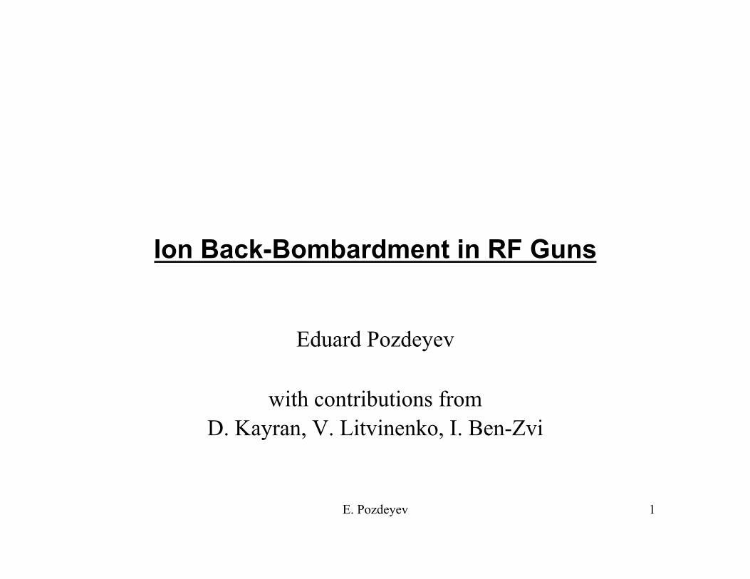
Photoguns
• Photoguns allow for – Short bunches – Good beam quality – Polarized beam
• Linac/ERL based accelerator drivers: – eRHIC and other Linac/ERL based colliders – Electron coolers, conventional high(er) energy and coherent – Light Sources and FELs
• Achieved operational current and life time: – DC, unpolarized: ~5 - 10 mA, ~500 C (?) (~10 h) – DC, polarized: <500 µA, ~500-1000 C – SRF Rosendorf, unpolarized: ~ 1 mA (was not routinely operated) – Cu RF ? No CW.
• More current (>100 mA) => longer cathode life time needed
E. Pozdeyev 3
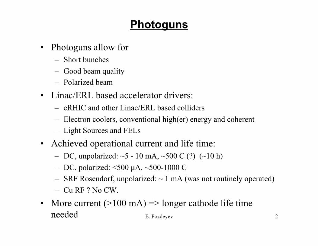
Ion Bombardment in DC photoguns
Ion back-bombardment is believed to be the main cause of degradation of quantum efficiency (QE) of photocathodes in DC photoguns.
cathode Ionized residual gas strikes photocathode
anode
A large portion of ions comes from the first few mm’s of the beam path. This problem is hard to overcome.
E. Pozdeyev 4
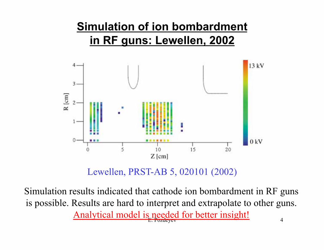
Simulation of ion bombardment in RF guns: Lewellen, 2002
Lewellen, PRST-AB 5, 020101 (2002)
Simulation results indicated that cathode ion bombardment in RF guns is possible. Results are hard to interpret and extrapolate to other guns.
Analytical model is needed for better insight!
E. Pozdeyev 5
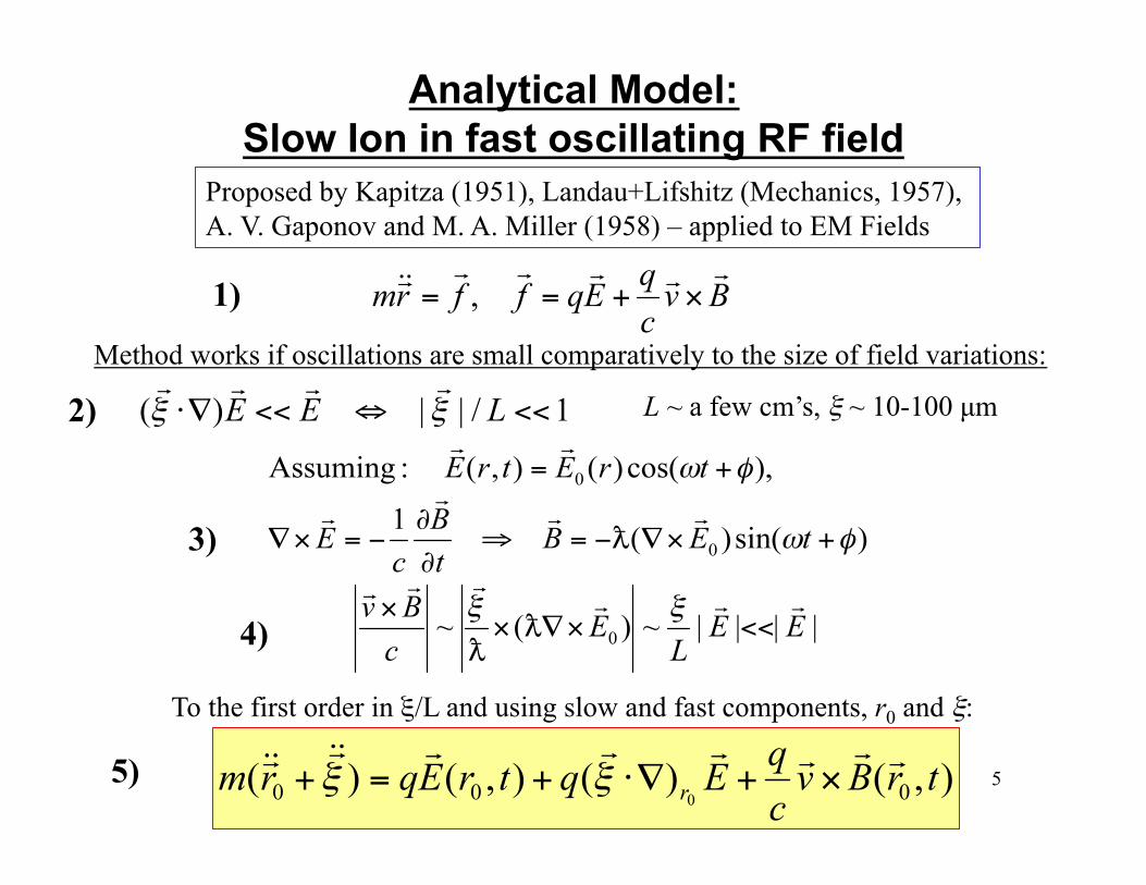
Analytical Model: Slow Ion in fast oscillating RF field
Proposed by Kapitza (1951), Landau+Lifshitz (Mechanics, 1957), A. V. Gaponov and M. A. Miller (1958) – applied to EM Fields
Method works if oscillations are small comparatively to the size of field variations:
L ~ a few cm’s, ξ ~ 10-100 µm
To the first order in ξ/L and using slow and fast components, r0 and ξ:
1)
2)
3)
4)
5)
E. Pozdeyev 6
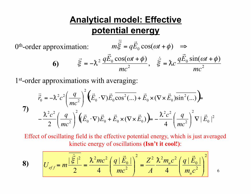
Analytical model: Effective potential energy
0th-order approximation:
1st-order approximations with averaging:
Effect of oscillating field is the effective potential energy, which is just averaged kinetic energy of oscillations (Isn’t it cool!):
6)
7)
8)
E. Pozdeyev 7
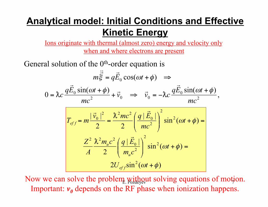
Analytical model: Initial Conditions and Effective Kinetic Energy
Ions originate with thermal (almost zero) energy and velocity only when and where electrons are present
General solution of the 0th-order equation is
Now we can solve the problem without solving equations of motion. Important: v0 depends on the RF phase when ionization happens.
E. Pozdeyev 8
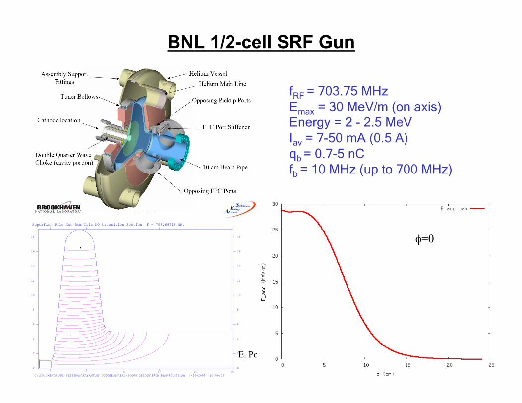
BNL 1/2-cell SRF Gun
fRF = 703.75 MHz Emax = 30 MeV/m (on axis) Energy = 2 - 2.5 MeV Iav = 7-50 mA (0.5 A) qb = 0.7-5 nC fb = 10 MHz (up to 700 MHz)
φ=0
E. Pozdeyev 9
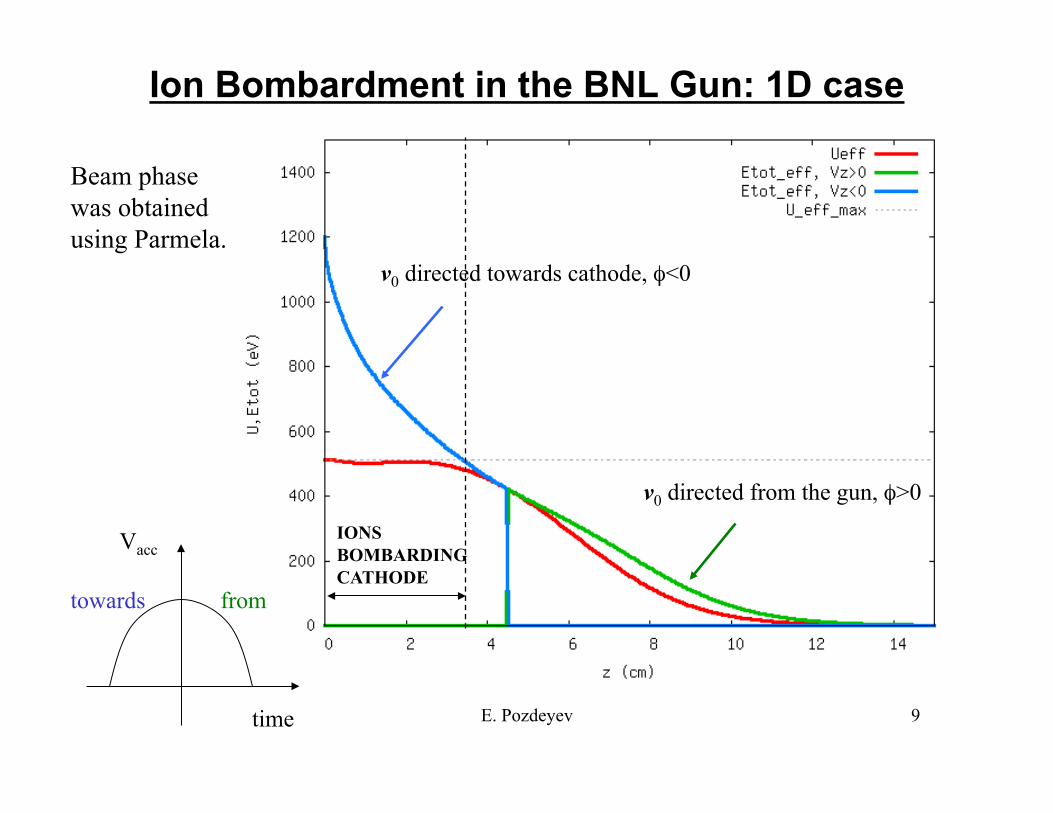
Ion Bombardment in the BNL Gun: 1D case
v0 directed towards cathode, φ<0
v0 directed from the gun, φ>0
IONS BOMBARDING CATHODE
time
Vacc
towards from
Beam phase was obtained using Parmela.
E. Pozdeyev 10
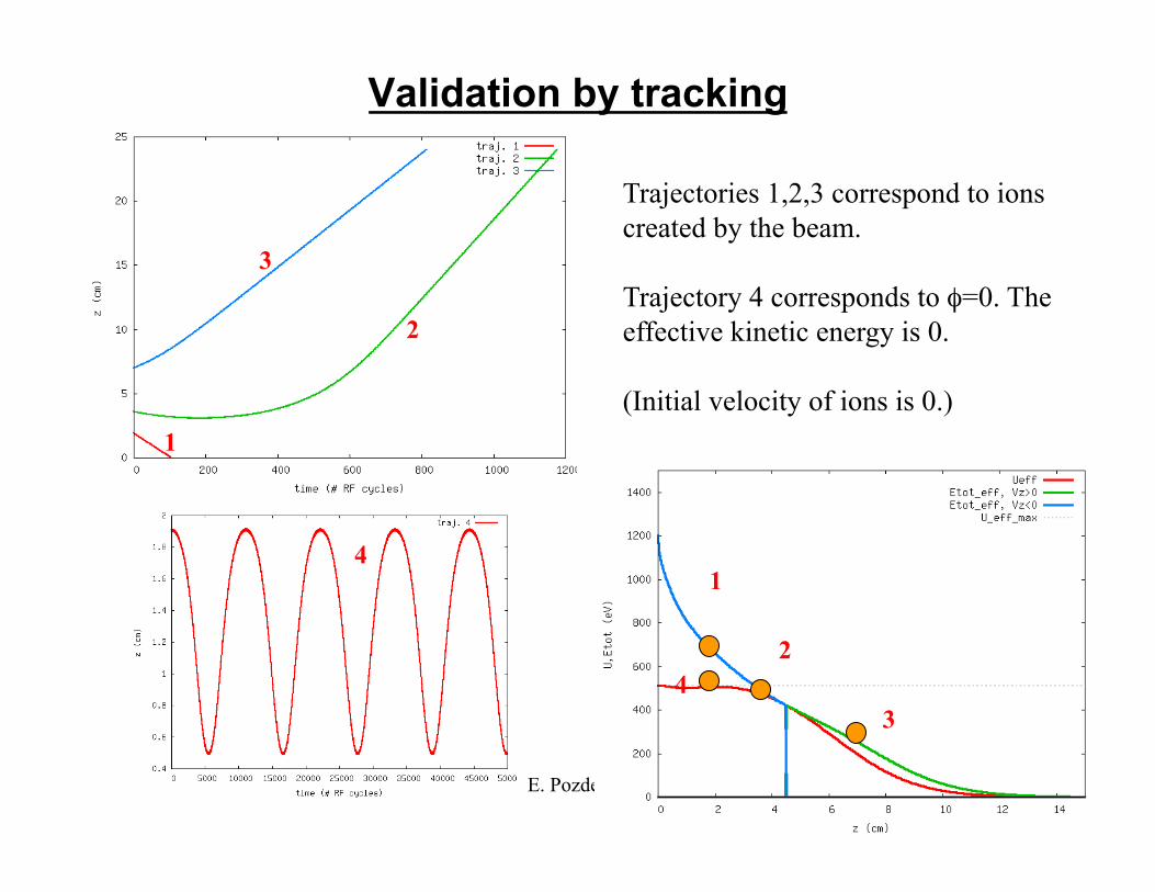
Validation by tracking
1
2
3 4
1
2
3
4
Trajectories 1,2,3 correspond to ions created by the beam.
Trajectory 4 corresponds to φ=0. The effective kinetic energy is 0.
(Initial velocity of ions is 0.)
E. Pozdeyev 11
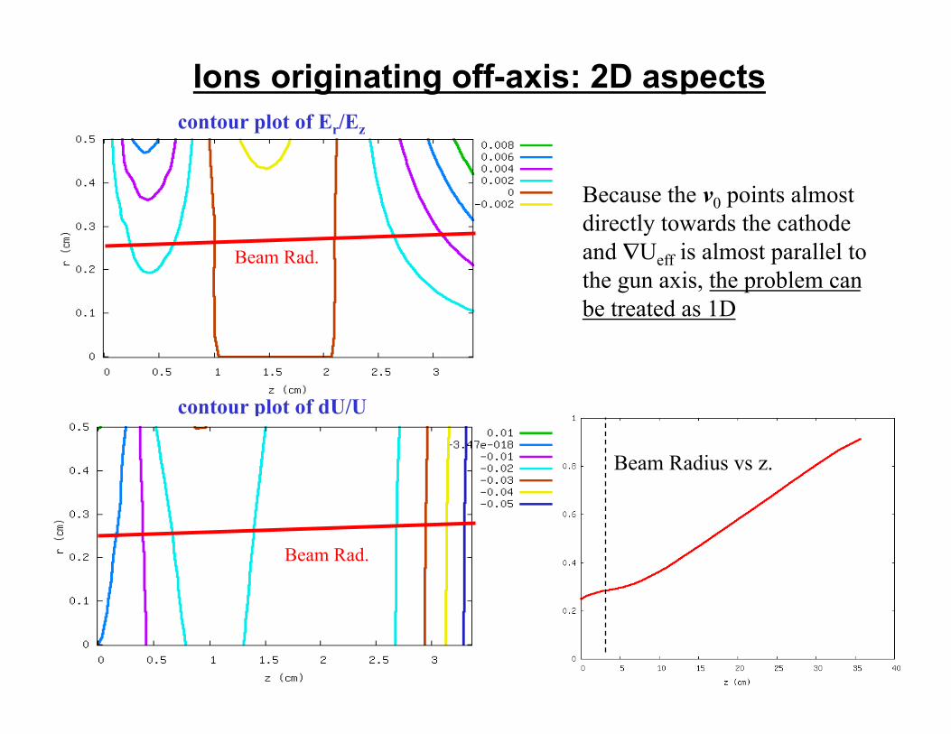
Ions originating off-axis: 2D aspects
Beam Radius vs z.
Beam Rad.
Because the v0 points almost directly towards the cathode and ∇Ueff is almost parallel to the gun axis, the problem can be treated as 1D
contour plot of Er/Ez
contour plot of dU/U
Beam Rad.
E. Pozdeyev 12
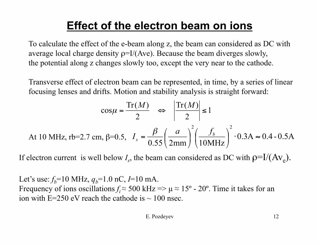
Effect of the electron beam on ions To calculate the effect of the e-beam along z, the beam can considered as DC with average local charge density ρ=I/(Ave). Because the beam diverges slowly, the potential along z changes slowly too, except the very near to the cathode.
Transverse effect of electron beam can be represented, in time, by a series of linear focusing lenses and drifts. Motion and stability analysis is straight forward:
At 10 MHz, rb=2.7 cm, β=0.5,
If electron current is well below Is, the beam can considered as DC with ρ=I/(Ave).
Let’s use: fb=10 MHz, qb=1.0 nC, I=10 mA. Frequency of ions oscillations fi ≈ 500 kHz => µ ≈ 15º - 20º. Time it takes for an ion with E=250 eV reach the cathode is ~ 100 nsec.
E. Pozdeyev 13
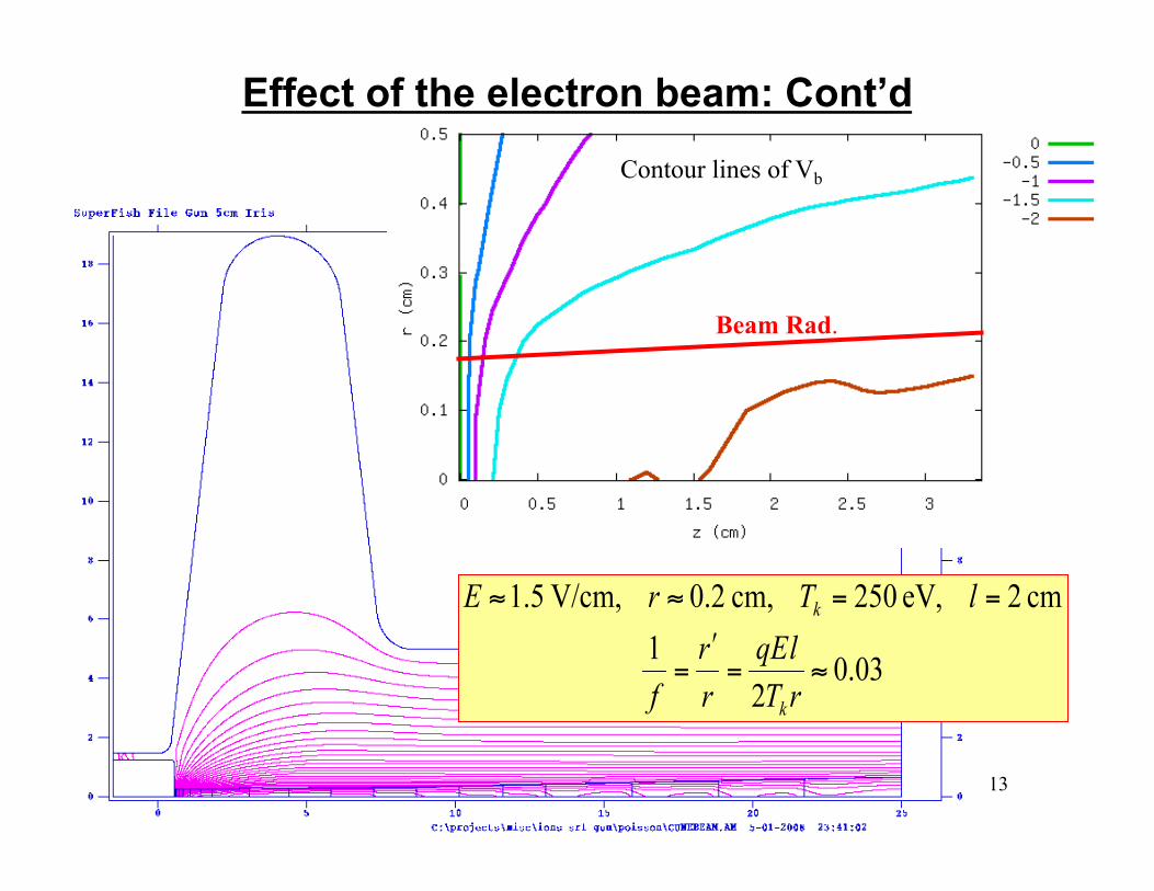
Effect of the electron beam: Cont’d
Beam Rad.
Contour lines of Vb
E. Pozdeyev 14
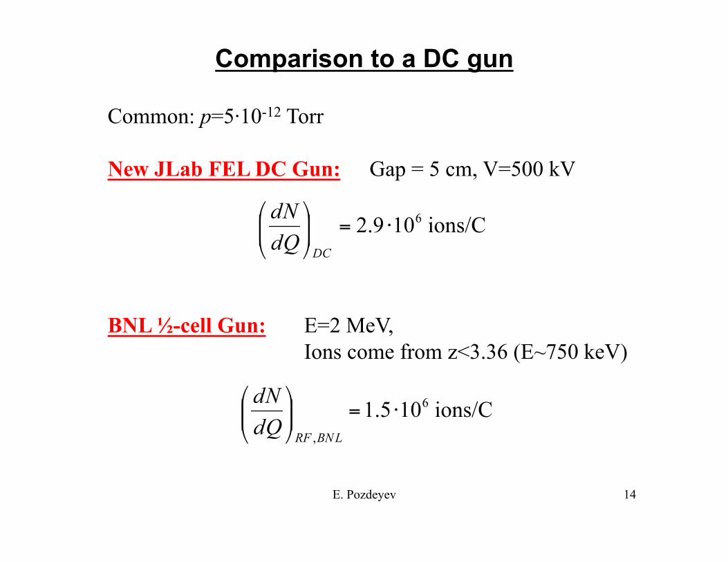
Comparison to a DC gun
Common: p=5·10-12 Torr
New JLab FEL DC Gun: Gap = 5 cm, V=500 kV
BNL ½-cell Gun: E=2 MeV, Ions come from z<3.36 (E~750 keV)
E. Pozdeyev 15
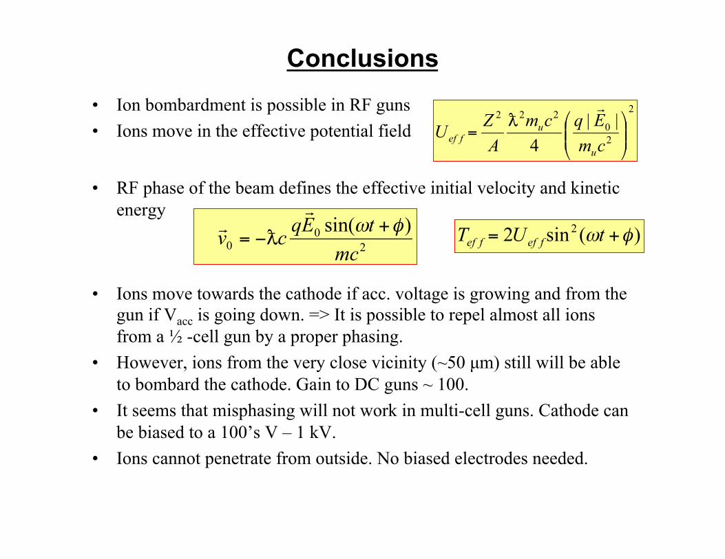
• Ion bombardment is possible in RF guns • Ions move in the effective potential field
• RF phase of the beam defines the effective initial velocity and kinetic energy
• Ions move towards the cathode if acc. voltage is growing and from the gun if Vacc is going down. => It is possible to repel almost all ions from a ½ -cell gun by a proper phasing.
• However, ions from the very close vicinity (~50 µm) still will be able to bombard the cathode. Gain to DC guns ~ 100.
• It seems that misphasing will not work in multi-cell guns. Cathode can be biased to a 100’s V – 1 kV.
• Ions cannot penetrate from outside. No biased electrodes needed.
Conclusions
E. Pozdeyev 16
Naive thoughts about Forever-Gun
• 1/2 –cell. Possibly shorter. • Misphasing to repel ions. Though, this might worsen
emittance and energy spread. • Lower voltage to avoid electron emission (Might be more
important than ions).
• This might work if high bunch charge or extremally good emittance is not required.
• More computer beam dynamics studies with misphasing needed
• Understanding effect of electron emission needed