Dynamic & Static Rated Fire Dampers, Ceiling … & Static Rated Fire Dampers, Ceiling Radiation...
16
June 2008 Dynamic & Static Rated Fire Dampers, Ceiling Radiation Dampers UL Classified High Free Area Minimal Pressure Drop
Transcript of Dynamic & Static Rated Fire Dampers, Ceiling … & Static Rated Fire Dampers, Ceiling Radiation...

June
2008
Dynamic & Static Rated Fire Dampers,
Ceiling Radiation Dampers� UL Classified � High Free Area � Minimal Pressure Drop

2
Fire Dampers,
Ceiling Radiation Dampers
Leading Edge Technical SupportAll Greenheck products are supported by the industry’s best product literature,
electronic media, and Computer Aided Product Selection program (CAPS). You’ll
also find extensive information on the internet.
You can always count on the personal service and expertise of our national and
international representative organizations. To locate your nearest Greenheck
representative, call 715-359-6171, or visit our website at
Quick Build and DeliveryGreenheck’s Quick Build (QB) program, along with strategic manufacturing locations,
ensures rapid response time. Products are manufactured the next day, or in three, five
or ten days, then efficiently shipped to your job site. On Greenheck's Quick Delivery
(QD) program, we have stock sizes of DFD's & CRD's available to ship the same day as
ordered.
Unparalleled In-house Testing CapabilitiesInternal testing capabilities are directly related to product quality and the ability
to meet stringent code requirements. With industry-leading testing abilities,
Greenheck can introduce new products faster, and can quickly develop qualified
products for your unique applications. Our dampers qualify to UL555, UL555C
and AMCA 500-D test standards.
A Global PresenceGreenheck operates four damper manufacturing locations, seven national distribution centers, and two
international distribution centers:
Manufacturing
�� Rocklin,�CA
�� Schofield,�WI
�� Frankfort,�KY
���Kunshan,�China
National Distribution
�� Schofield,�WI
�� Rocklin,�CA
�� Dallas,�TX�
���Miami,�FL
�� Greensboro,�NC
�� Union,�NJ
�� Columbus,�OH
International Distribution
�� Dubai
�� Mexico
The Greenheck DifferenceWhat makes Greenheck different from other damper manufacturers?
Perhaps it’s having the most UL certified dampers, or the industry-
leading testing capabilities. Most Greenheck dampers meet California
State�Fire�Marshal�and�NY�MEA�requirements.�Aggressive�research�
and development also keeps Greenheck a major player in the damper
industry.

3
Design and Construction Features
Multi-blade DFD’s
Reinforced Corner DesignTog-L-Loc®, Greenheck’s reinforced corner design, is incorporated into every
Greenheck multi-blade fire damper frame. It provides higher structural rigidity than
many competitors’ welded frames. The design also ensures that every frame has square
corners, helping prevent blades from binding on the frame and making damper operation
much smoother due to less friction.
Maximized Free Area and Minimized Pressure DropGreenheck’s Variable Symmetrical Blade Design (VSB), available on multi-
blade models, uses a combination of four symmetrical blade sizes– 4, 5,
6, and 7 inch (102, 127, 152, and 178 mm) – to maximize the free area at
any given height and minimize pressure drop. The VSB design also allows
for consistent operating characteristics regardless of airflow direction.
Traditional damper designs utilize only one blade width – usually 6 or 7 inch
(152 or 178 mm) – which reduces manufacturing costs, but compromises the
dampers’ performance capabilities by having cutoff or extended blades and
performance robbing oversized closure strips.
Low Profile FrameLow profile top and bottom frames, standard on all dampers 17 in. (432 mm) high or
less, optimize free area on smaller dampers and reduce pressure loss.
TransitionsWhen a rectangular multi-blade fire damper is being used in conjunction with round or
oval ductwork, they can be supplied in a factory sleeve with round or oval transitions
on both ends of the sleeve. Dampers should be ordered to the duct dimensions.
OptionsOpen Close Indicator (OCI) - The OCI option provides two switches, one set
of contacts to close when the damper blades are at their open position, and
the other set to close when the damper blades are at their closed position.
The switches are physically linked to a damper blade and therefore give a true
representation of the damper’s position.
Factory Sleeve - Fire Dampers are available in factory furnished sleeves.
Sleeves are galvanized steel and are available in 10 through 20 ga. (3 mm
through 1 mm) thicknesses and lengths up to 48 in. (1219 mm).
ActuatorTorque
ActuatorTorque
Airflow worksagainstactuator
Airflow worksagainstactuator
Airflowworks with
actuator
Unbalanced BladeRequires Higher Torque
Balanced Blade Requires Less Torque
FreeArea
FreeArea
Competitor Greenheck
TYPE R TYPE O TYPE C
ADamperLocation
L
CL Damper Frame
Sleeve
Damper D*
D* + 2 in. sq.
4
Fire Rated Partition
Factory Supplied
Thermal Blanket
Fire Damper
Grille
(Supplied
by others)
7 1/2
in.
max.
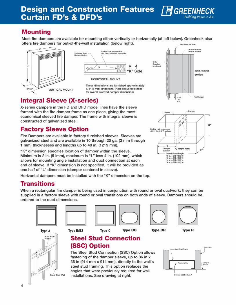
Design and Construction FeaturesCurtain FD’s & DFD’s
3 11 / 16"
W*
H*
Stainless SteelClosur e Spring
Fusible Link (replaceable) 165 ° Standard (212 ° available)
HORIZONTAL�MOUNT�
VER�TICAL�MOUNT
* These dimensions are furnished approximately
1/4" (6 mm) undersize. (Add sleeve thickness
for overall sleeved damper dimension)
�K��Side
MountingMost fire dampers are available for mounting either vertically or horizontally (at left below). Greenheck also
offers fire dampers for out-of-the-wall installation (below right).
Type A Type B/B2 Type C
Integral Sleeve (X-series)X-series�dampers�in�the�FD�and�DFD�model�lines�have�the�sleeve�
formed with the fire damper frame as one piece, giving the most
economical sleeved fire damper. The frame with integral sleeve is
constructed of galvanized steel.
Factory Sleeve OptionFire Dampers are available in factory furnished sleeves. Sleeves are
galvanized steel and are available in 10 through 20 ga. (3 mm through
1 mm) thicknesses and lengths up to 48 in. (1219 mm).
�K��dimension�specifies�location�of�damper�within�the�sleeve.�
Minimum�is�2�in.�(51mm),�maximum�is��L��less�4�in.�(102�mm),�which�
allows for mounting angle installation and duct connection at each
end�of�sleeve.�If��K��dimension�is�not�specified,�it�will�be�provided�as�
one�half�of��L��dimension�(damper�centered�in�sleeve).
Horizontal�dampers�must�be�installed�with�the��K��dimension�on�the�top.
TransitionsWhen a rectangular fire damper is being used in conjunction with round or oval ductwork, they can be
supplied in a factory sleeve with round or oval transitions on both ends of sleeve. Dampers should be
ordered to the duct dimensions.
Type CO Type CR Type R
Steel Stud Connection
(SSC) OptionThe Steel Stud Connection (SSC) Option allows
fastening of the damper sleeve, up to 36 in x
36 in (914 mm x 914 mm), directly to the wall's
steel stud framing. This option replaces the
angles that were previously required for wall
installations. See drawing at right.
A-A
Steel StudFrame
Steel Stud Wall
Steel Stud FrameWallboard
Retaining Bar DamperSleeve
Cross-Section A-A
H *
KDamper Location W *
CL Damper Fram
Sleeve
CL Damper Frame
Damper
Overall Sleeve Length
12 in. = DFD-150X1210 in. = DFD-150X10
14 in. = DFD-150X1416 in. = DFD-150X16
Fusible Link (replaceable)(165º F Std., 212º F available)
OFD/ODFD
series

5
Options and Accessoriesfor FD’s & DFD’s
Helpful Installation DecalsGreenheck dampers come complete with decals highlighting damper
areas that are important for an accurate installation. Our decals point out
critical damper areas and include messages like “Do not install screws
here.” We are the only damper manufacturer to offer these simple yet very
helpful tips right on the damper.
Single Side Retaining Angles and PlatesRectangular dampers and sleeve assemblies up to a maximum size (W x H, in., W x H, mm) of 80 x 50
(2032 x 1270), 50 x 80 (1270 x 2032), or 40 x 100 (1016 x 2540) require retaining angles on one side of the
partition only for 1 1/2 hour dampers. Round dampers and sleeve assemblies up to a maximum diameter of
24 in. (610 mm) require retaining plates on one side only. Damper assemblies exceeding these maximum
sizes must be secured with retaining angles or plates on both sides of the partition.
Retaining AnglesSave time by letting Greenheck install retaining angles for you. You can
order your retaining angles four different ways:
� Single Fastened - one retaining angle �ounted in the location you want
� Single Wrapped - one retaining angle wrapped around the da�per sleeve
and wire tied
� Double Wrapped - the sa�e feature as single wrapped but, with 2 sets of
retaining angles
� Fastened & Wrapped - one retaining angle fastened and one angle
wrapped around the damper
Breakaway ConnectionsGreenheck was the first manufacturer to successfully UL qualify a universal
breakaway duct connection that is co�patible with TDC, TDF, Duct�ate,
Nexus or Ward flange systems. You now have the option to choose the
universal breakaway connection on fire dampers, smoke, and combination
fire smoke dampers. You can order your dampers with breakaway connection
three different ways:
� Universal flange attached to one end of the sleeve
� Universal flange attached to both ends of the sleeve
� One end attached and one shipped loose
S & Drive connection uses drive slip connection on the side of the he��ed
sleeve and S-slip joints are used on top and botto�.
Access DoorsAccording to NFPA 80 (2007 edition) & NFPA 90A (2002 edition), an access door needs to be provided in air
ducts adjacent to each mre da�per, s�oke da�per, or co�bination mre s�oke da�per for �aintenance and
inspection. Save time and money by letting Greenheck install the access door in the sleeve to save on labor
cost in the meld.
Security BarsWhen a specification requires security bars to be installed with the damper, they can
be shipped assembled. Installation of security bars into dampers reduces security
risks and reinforces the equipment. Security bars maintain the UL classification for
all products. The standard product is welded into the sleeve. The minimum size is
8 in. x 6 in. (203 mm x 152 mm), and the maximum size is limited to maximum size of
damper.
Grille TabsThe Grille Tab option provides mounting flanges on the sleeve to ease installation of grilles in the field. The
flanges are concealed when the grille is installed.
LINE OF WALL
DO NOT INSTALL SCREWSBETWEEN THESE LINESAROUND ENTIRE DAMPER
5.500
3.250
(2) .375 DIA. HOLES
4585490.375
2.875

6
Design and Construction Features
DFDR’s & FDR’s
MountingRound fire dampers are available for mounting either vertically or horizontally. Only one retainer plate is
required for mounting of damper. Dampers are supplied with sleeves from the factory and can be installed
without the need for additional field installed sleeves.
Retainer Plate
Duct Connection
Area
2 in .
AIRFLOW
6 in. max.
TW
Sleeve Length
6 in. max.
Do not place retainer
plate in this groove
2 in .
Duct connection
Area
Clearance for expansion
Retainer plate
Blade latch
Access door to be on
same side as blade latch
DFDR-XXX Blade Orientation
Normal30°�Off�Horizontal
(Maximum)
30°�Off�Horizontal
(Maximum)
Axle
Axle
Axle30°
30°
CLAMPING SCREW
RETAININGPLATE ASSEMBLY
NUTRound one-piece retaining plates easily wrap around the
sleeve of the damper and tighten with the clamping screw for
simplified installation. They are designed to mount flush to the
wall/floor and hold the damper in the opening. One retaining
plate is provided with the damper.
Retaining Plates
Wall Thickness in. (mm) Sleeve Length in. (mm)
Up to 6.5 (165) 13.625 (346)
Up to 8.5 (216) 15.625 (397)
Up to 10.5 (267) 17.625 (448)
Over 10.5 (267) Consult Greenheck

7
Design and Construction Features
CRD’s
Mounting
OptionsVolume Controller Option - A volume controller gives
you the ability to regulate the airflow thru the damper by
manually setting the blades at a given angle. Adjusting the
screw will open and close the blades.
CRD-1 butterfly CRD-2 round butterfly
CRD-60 curtain blade styleCRD-60 curtain blade style
with skirt
Greenheck’s CRD models have been tested and labeled for protection of ceiling openings in fire rated
floor/ceiling assemblies with fire resistance ratings of three hours or less. They can also be applied to steel
lay-in style ceiling diffusers up to 24 in. x 24 in. (610 mm x 610 mm) maximum size when installed with an
approved�thermal�blanket.�Models�CRD-1�and�CRD-2�are�Warnock�Hersey�listed�for�wood�construction�
barriers.
CRD-1LP low profile butterfly
Model and Size
Limitations
Model
Minimum
Size
in. (mm)
Maximum
Size
in. (mm)
Butt
erfl
y S
tyle
CRD-14 x 6
(102 x 152)
24 x 24
(610 x 610)
LOW PROFILE
CRD-1LP
4 x 12
(102 x 305)
24 x 24
(610 x 610)
Curt
ain
Sty
le
CRD-606 x 4
(152 x 102)
24 x 24
(610 x 610)
B-TYPE
CRD-60B
6 x 4
(152 x 102)
24 x 24
(610 x 610)
CRD-60X6 x 4
(152 x 102)
24 x 24
(610 x 610)
Round
CRD-2 5 (127) 24 (610)Note: Damper is shown upside down to illustrate
volume controller.

8
Pressure loss through an open damper (change
in pressure) is a performance criteria required to
appropriately select and apply a fire life safety
damper�in�an�HVAC�system.
Any damper’s pressure loss depends on
where and how the damper is installed in the
HVAC�system.�AMCA�Standard�500-D�defines�
several configurations to be used for testing
damper pressure drop. Greenheck has tested
its dampers for pressure loss in the three test
figures shown and provides data for each.
Actual�pressure�loss�found�in�any�HVAC�system�
is a combination of many factors. This pressure
loss information, along with an analysis of other
system influences, should be used to estimate
actual pressure losses for a damper installed in
a�given�HVAC�system.
Pressure LossPressure Loss testing was conducted in accordance with AMCA
Standard 500-D. All data has been corrected to represent standard air at
a density of 0.075 lb/ft3 (1.2 kg/m3).
Damper Performance
Testing Criteria
Greenheck Fan Corp. certifies that the models
DFD-210,�DFD-230,�DFDTF-210,�SEDFD-210,�and�
SSDFD-210 shown herein are licensed to bear
the AMCA Seal. The ratings shown are based on
tests and procedures performed in accordance
with AMCA Publication 511 and comply with
the requirements of the AMCA Certified Ratings
Programs. The AMCA Certified Ratings Seal
applies to air performance ratings only.
D=Duct length
W=Damper width
H=Damper�height
5D 6D
5D
D 4 (W) (H)3.14
Fig
. 5
.3Fig
. 5
.2Fig
. 5
.5
Figure 5.3 illustrates a fully ducted damper.
Figure 5.2 illustrates a ducted damper exhausting air
into an open area.
Figure 5.5 illustrates a plenum mounted damper.
Dimension (in.) 12 x 12 24 x 24 36 x 36 12 x 48 48 x 12
(mm) 305 x 305 610 x 610 914 x 914 305 x 1219 1219 x 305
Velocity (fpm) Pressure Drop - in. wg
500 .04 .02 .01 .01 .03
1000 .14 .07 .04 .06 .10
1500 .32 .15 .09 .13 .23
2000 .56 .27 .16 .23 .41
2500 .88 .42 .25 .36 .63
3000 1.26 .61 .36 .52 .91
3500 1.72 .83 .49 .70 1.24
4000 2.24 1.08 .64 .92 1.62
DFD-210, 230, DFDTF-210,
SEDFD-210, & SSDFD-210
AMCA Figure 5.2 Pressure Drop
Dimension (in.) 12 x 12 24 x 24 36 x 36 12 x 48 48 x 12
(mm) 305 x 305 610 x 610 914 x 914 305 x 1219 1219 x 305
Velocity (fpm) Pressure Drop - in. wg
500 .06 .03 .03 .03 .04
1000 .22 .14 .12 .13 .17
1500 .50 .31 .26 .30 .38
2000 .89 .55 .47 .53 .67
2500 1.39 .86 .73 .83 1.04
3000 2.00 1.24 1.05 1.19 1.50
3500 2.73 1.69 1.42 1.62 2.05
4000 3.56 2.20 1.86 2.11 2.67
DFD-210, 230, DFDTF-210,
SEDFD-210, & SSDFD-210
AMCA Figure 5.5 Pressure Drop
Dimension (in.) 12 x 12 24 x 24 36 x 36 12 x 48 48 x 12
(mm) 305 x 305 610 x 610 914 x 914 305 x 1219 1219 x 305
Velocity (fpm) Pressure Drop - in. wg
500 .02 .01 .01 .01 .02
1000 .09 .04 .03 .04 .07
1500 .20 .09 .06 .10 .16
2000 .36 .16 .11 .17 .29
2500 .56 .25 .17 .27 .45
3000 .81 .35 .24 .39 .64
3500 1.10 .48 .33 .53 .88
4000 1.44 .63 .42 .70 1.14
DFD-210, 230, DFDTF-210,
SEDFD-210, & SSDFD-210
AMCA Figure 5.3 Pressure Drop
Note: Curtain style fire damper pressure drop
data is available on www.greenheck.com

9
Model Number Codes
CLOSURE RATINGDFD (dynamic)For�use�in�HVAC�systems�that�are�operational�in�the�event of fire.
SEDFD 316 stainless steel dynamic ratedSSDFD 304 stainless steel dynamic ratedDFDTF Thin frame dynamic ratedDFDAF Airfoil blade dynamic rated
BLADE STYLE
2 Fabricated Steel with Triple Vee Reinforcements (3V)
3 Fabricated Steel Airfoil Style Blade
FIRE RESISTANCE RATING
1 (11⁄2 hour)For use in walls, floors and partitions with fire resistance ratings of less than 3 hours.
3 (3 hour)For use in walls, floors and partitions with fire resistance ratings of 3 hours or more.
PRESSURE RATING
0 =Pressure rating up to 4 in wg (1 kPa)
DFD -210
DFD -150X12
FIRE DAMPER MODEL NUMBER CODEThe fire damper model number consists of 5 individual components that make up a specific fire damper's construction.
The model number breakdown and corresponding explanation of each component help insure the correct fire damper
selection for your application.
CLOSURE RATING
DFD (dynamic)For�use�in�HVAC�systems�that�are�operational�in�the�event of fire.
ODFD Out of wall dynamic rated
FD (static)For�use�in�HVAC�systems�that�are�automatically�shut�down in the event of fire.
OFD Out of wall static rated
PRESSURE RATING
0 = Low to Medium Pressure Classes up to
2 in. wg (.5 kPa)
5 = High Pressure Classes up to 3 in. wg
(.75 kPa) or higher and Seal Classes A or B
DAMPER WITH INTEGRAL 20 GA. SLEEVE
(Economical�factory�assembled�damper�with�
sleeve)
X10 = 10 in. long (254 mm)
X12 = 12 in. long (304 mm)
X14 = 14 in. long (355 mm)
X16 = 16 in. long (406 mm)
FIRE RESISTANCE RATING
1 (11⁄2 hour)For use in walls, floors, and partitions with fire resistance ratings of less than 3 hours.
3 (3 hour)For use in walls, floors and partitions with fire resistance ratings of 3 hours or more.
FRAME STYLE (depth)
0 = Ultrathin - 11⁄2 in. (38 mm)
1 = Narrowline�-�2 3⁄16 in. (56 mm)
5 = Standard - 3 11⁄16 in. (94 mm)
1
2
3
4
5
1 2 3 4 5
1 2 3 4
1
2
3
4
CLOSURE RATING
CRD (ceiling radiation)For use in ceiling openings with fire resistance ratings of 3 hours or less.
BLADE STYLE
1 Rectangular
2 Round
60 Curtain type
SPECIAL FEATURES
LP Low profile
X Insulation skirt
B B style
1
2
3
CRD -1LP1 2 3
10
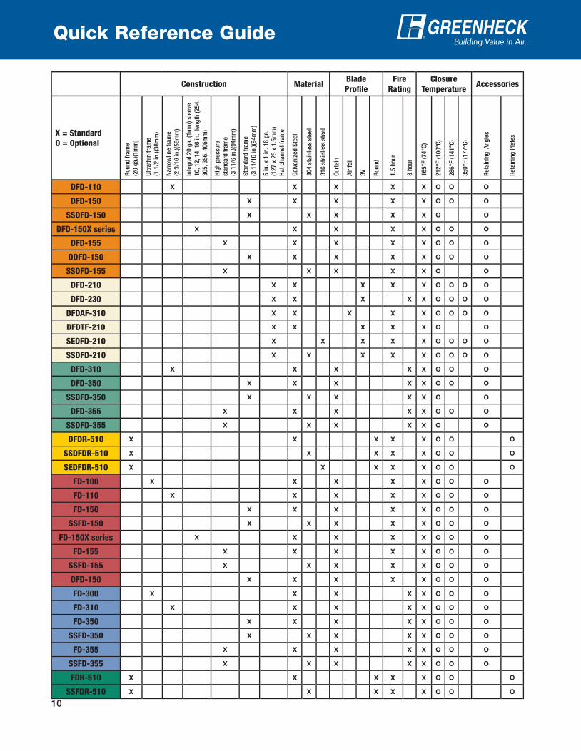
Quick Reference Guide
Accessories
Reta
inin
g P
late
s
O
O
O
O
O
Reta
inin
g A
ng
les
O
O
O
O
O
O
O
O
O
O
O
O
O
O
O
O
O
O
O
O
O
O
O
O
O
O
O
O
O
O
O
O
Closure
Temperature
350°F
(177°C
)O
O
O
O
O
286°F
(141°C
)
O
O
O
O
O
O
O
O
O
O
O
O
O
O
O
O
O
O
O
O
O
O
O
O
O
O
O
O
O
O
O
O
212°F
(100°C
)
O
O
O
O
O
O
O
O
O
O
O
O
O
O
O
O
O
O
O
O
O
O
O
O
O
O
O
O
O
O
O
O
O
O
O
O
O
165°F
(74°C
)
X
X
X
X
X
X
X
X
X
X
X
X
X
X
X
X
X
X
X
X
X
X
X
X
X
X
X
X
X
X
X
X
X
X
X
X
X
Fire
Rating
3 h
ou
r
X
X
X
X
X
X
X
X
X
X
X
X
1.5
hou
r
X
X
X
X
X
X
X
X
X
X
X
X
X
X
X
X
X
X
X
X
X
X
X
X
X
Blade
Profile
Rou
nd
X
X
X
X
X
3V
X
X
X
X
X
Air
foil
X
Cu
rtain
X
X
X
X
X
X
X
X
X
X
X
X
X
X
X
X
X
X
X
X
X
X
X
X
X
XMaterial
316 s
tain
less
ste
el
X
X
304 s
tain
less
ste
el
X
X
X
X
X
X
X
X
X
X
X
Galv
an
ized
Ste
el
X
X
X
X
X
X
X
X
X
X
X
X
X
X
X
X
X
X
X
X
X
X
X
X
Construction
5 in
. x
1 in
. 16 g
a.
(127 x
25 x
1.5
mm
)
Hat
chan
nel fr
am
e
X
X
X
X
X
X
Sta
nd
ard
fra
me
(3 1
1/1
6 in
.)(9
4m
m)
X
X
X
X
X
X
X
X
X
X
Hig
h p
ress
ure
stan
dard
fra
me
(3 1
1/6
in
.)(9
4m
m)
X
X
X
X
X
X
X
X
Inte
gra
l 20 g
a. (1
mm
) sl
eeve
10, 1
2, 1
4, 1
6 in
. len
gth
(254,
305, 3
56, 4
06m
m)
X
X
Narr
ow
line f
ram
e
(2 3
/16 in
.)(5
6m
m)
X
X
X
XU
ltra
thin
fra
me
(1 1
/2 in
.)(3
8m
m)
X
X
Rou
nd
fra
me
(20 g
a.)
(1m
m)
X
X
X
X
X
X = Standard
O = Optional
DFD-110
DFD-150
SSDFD-150
DFD-150X series
DFD-155
ODFD-150
SSDFD-155
DFD-210
DFD-230
DFDAF-310
DFDTF-210
SEDFD-210
SSDFD-210
DFD-310
DFD-350
SSDFD-350
DFD-355
SSDFD-355
DFDR-510
SSDFDR-510
SEDFDR-510
FD-100
FD-110
FD-150
SSFD-150
FD-150X series
FD-155
SSFD-155
OFD-150
FD-300
FD-310
FD-350
SSFD-350
FD-355
SSFD-355
FDR-510
SSFDR-510

11
Model and SizeLimitations
Static Fire Dampers
Model Mounting
Horizon-
tal or
Vertical
(H or V)
Maximum Single Section Size W X H, in. (mm) Maximum Multi Section W x H, in. (mm)
No Transitions
or
A styleB/B2 C & CO CR
R
A B C & CO CR0 in.
offset
1 in.
offset
2 in.
offset
1.5
Hour
FD-100V
48 x 48
(1219 x 1219)
48 x 40
(1219 x 1016)
--- --- --- ---
FD-110H or V
48 x 48
(1219 x 1219)
48 x 43
(1219 x 1092)
--- --- --- ---
FD-150
H or V48 x 48
(1219 x 1219)
48 x 43
(1219 x 1092)
46 x 42
(1168 x 1067)
42
(1067)
30
(762)
47
(1194)
46
(1168)
96 x 48 or
120 x 40
(2438 x 1219)
or
(3048 x 1016)
96 x 43 or
120 x 35
(2438 x
1092) or
(3048 x 889)
94 x 42 or
118 x 34
(2438 x 1067)
or
(2997 x 864)
68
(1727
V48 x 48
(1219 x 1219)
48 x 43
(1219 x 1092)
46 x 42
(1168 x 1067)
42
(1067)
30
(762)
73
(1854)
72
(1829)
74 x 74
(1880 x 1880)
74 x 69
(1880 x 1753)
72 x 68
(1829 x 1727)
68
(1727)
FD-150X10
FD-150X12
FD-150X14
FD-150X16
H or V48 x 48
(1219 x 1219)
48 x 43
(1219 x 1092)
46 x 42
(1168 x 1067)
42
(1067)
30
(762)
47
(1194)
46
(1168)
96 x 48 or
120 x 40
(2438 x 1219)
or
(3048 x 1016)
96 x 43 or
120 x 35
(2438 x
1092) or
(3048 x 889)
--- ---
SSFD-150
H36 x 36
(914 x 914)
36 x 32
(914 x 813)
34 x 31
(864 x 787)
31
(787)
30
(762)
35
(889)
34
(864)
---
V
48 x 48
(1219 x 1219)
48 x 43
(1219 x 1092)
46 x 42
(1168 x 1067)
42
(1067)
30
(762)
47
(1194)
46
(1168)
96 x 48 or
120 x 40
(2438 X
1219) or
(3048 x 1016)
96 x 43 or
120 x 35
(2438 x 1092)
or
(3048 x 889)
94 x 42 or
118 x 34
(2438 x 1067)
or
(2997 x 864)
---
FD-155
H or V
--- --- 46 x 42
(1168 x 1067)
42
(1067)
30
(762)
47
(1194)
46
(1168)
--- --- 96 x 42 or
118 x 34
(2438 x 1067)
or
(2997 x 864)
68
(1727)
V--- --- 46 x 42
(1168 X 1067)
42
(1067)
30
(762)
73
(1854)
72
(1829)
--- --- 72 x 68
(1829 x 1727)
68
(1727)
SSFD-155
H--- --- 34 x 31
(864 x 787)
31
(787)
30
(762)
35
(889)
34
(964)
--- --- --- ---
V
--- --- 46 x 42
(1168 x 1067)
42
(1067)
30
(762)
47
(1194)
46
(1168)
--- --- 96 x 42 or
118 x 34
(2438 x 1067)
or
(2997 x 864)
---
OFD-150H or V
36 x 36
(914 x 914)
--- --- --- --- ---
FDR-510 H or V 24 (610) --- --- --- --- ---
SSFDR-510 H or V 24 (610) --- --- --- --- ---
3 h
our
FD-300V
48 x 48
(1219 x 1219)
48 x 40
(1219 x 1016)
--- --- --- --- --- ---
FD-310V
48 x 48
(121 9 x 1219)
48 x 43
(1219 x 1092)
--- --- --- --- --- ---
FD-350
H40 x 40
(1016 x 1016)
40 x 35
(1016 x 889)
38 x 34
(965 x 864)
34
(864)
30
(762)
39
(991)
38
(965)
80 x 40
(2032 x 1016)
80 x 35
(2032 x 889)
78 x 34
(1981 x 864)
---
V48 x 48
(1219 x 1219)
48 x 43
(1219 x 1092)
46 x 42
(1168 x 1067)
42
(1067)
30
(762)
47
(1194)
46
(1168)
---
FD-355
H--- --- 38 x 34
(965 x 864)
34
(864)
30
(762)
39
(991)
38
(965)
--- --- 78 x 34
(1981 x 864)
---
V--- --- 46 x 42
(1168 x 1067)
42
(1067)
30
(762)
47
(1194)
46
(1168)
---
SSFD-350V
48 x 48
(1219 x 1219)
48 x 43
(1219 x 1092)
46 x 42
(1168 x 1067)
42
(1067)
30
(762)
47
(1194)
46
(1168)
---
SSFD-355V
--- --- 46 x 42
(1168 x 1067)
42
(1067)
30
(762)
47
(1194)
46
(1168)
---

12
Model and SizeLimitations
Dynamic Fire Dampers
Model
Maximum
Temperature
°F/°C
Maximum Size W X H, in. (mm)
Maximum
Velocity
fpm (m/s)
Maximum
Pressure
in. wg
(kPa)
No Transitions or A style
B/B2 C & CO CR
R
Single
Section
Multi
Section
0 in.
offset
1 in.
offset
2 in.
offset
DFD-110
165°/74°
36 x 36 (V) or
30 x 30 (H)
(914 x 914) or
(762 x 762)
---
36 x 32 (V) or
30 x 26 (H)
(914 x 813) or
(762 x 660)
--- --- ---
2000 (10),
4000 (20) up
to 24 x 24
(610 x 610),
165°F (74°C)
only
4 (1)
212°/100°
36 x 36 (V) or
30 x 30 (H)
(914 x 914) or
(762 x 762)
---
36 x 32 (V) or
30 x 26 (H)
(914 x 813) or
(762 x 660)
286°/141°24 x 24
(610 x 610)---
24 x 21
(610 x 533)
DFD-150
165°/74°
36 x 36 (V) or
30 x 30 (H)
(914 x 914) or
(762 x 762)
72 x 48 or
60 x 60 (V) ;
48 x 36 (H)
(1829 x 1219) or
(1524 x 1524);
(1219 x 914)
72 x 45 or
60 x 56 (V);
48 x 32 (H)
(1829 x 1143) or
(1524 x 1422);
(1219 x 813)
70 x 44 or
58 x 55 (V);
46 x 31 (H)
(1778 x 1118) or
(1473 x 1397);
(1168 x 787)
55 (V))
or 31 (H)
(1397)
or (787)
30 (762)
59 (V)
or 35
(H)
(1499)
or (889)
58 (V)
or 34 (H)
(1473)
or (864)2000 (10),
4000 (20) up
to 24 x 24
(610 x 610),
165°F (74°C)
only
4 (1)
212°/100°
36 x 36 (V) or
30 x 30 (H)
(914 x 914) or
(762 x 762)
48 x 36
(1219 x 914)
48 x 32
(1219 x 813)
46 x 31
(1168 x 787)
31
(787)
30
(762)
35
(889)
34
(864)
286°/141°24 x 24
(610 x 610)
24 x 24
(610 x 610)
24 x 21
(610 x 533)
22 x 20
(559 x 508)
20
(508)
24
(610)
23
(584)
22
(559)
DFD-155
165°/74°
36 x 36 (V) or
30 x 30 (H)
(914 x 914) or
(762 x 762)
--- ---
70 x 44 or
58 x 55 (V);
46 x 31 (H)
(1778 x 1118) or
(1473 x 1397);
(1168 x 787)
55 (H) or
31 (V)
(1397) or
(787)
30 (762)
59 (V) or
35 (H)
(1499)
or (889)
58 (V) or
34 (H)
(1473)
or (864)2000 (10),
4000 (20) up
to 24 x 24
(610 x 610),
165°F (74°C)
only
4 (1)
212°/100°
36 x 36 (V) or
30 x 30 (H)
(914 x 914) or
(762 x 762)
--- ---46 x 31
(1168 x 787)
31
(787)
30
(762)
35
(889)
34
(864)
286°/141°24 x 24
(610 x 610)--- ---
22 x 20
(559 x 508)
20
(508)
24
(610)
23
(584)
22
(559)
DFD-150X10
DFD-150X12
DFD-150X14
DFD-150X16
165°/74°
36 x 36 (V) or
30 x 30 (H)
(914 x 914) or
(762 x 762)
72 x 48 or
60 x 60 (V) ;
48 x 36 (H)
(1829 x 1219) or
(1524 x 1524);
(1219 x 914)
72 x 45 or
60 x 56 (V);
48 x 32 (H)
(1829 x 1143) or
(1524 x 1422);
(1219 x 813)
34 x 31 (V)
(864 x 787)
28 x 25 (H)
(711 x 635)
31 (V) or
25 (H)
(787 or 635)
---
35 (V)
(889)
29 (H)
(737)
34 (V)
(864)
28 (H)
(711)2000 (10),
4000 (20) up
to 24 x 24
(610 x 610),
165°F (74°C)
only
4 (1)
212°/100°
36 x 36 (V) or
30 x 30 (H)
(914 x 914) or
(762 x 762)
48 x 36
(1219 X 914)
48 x 32
(1219 x 813)
34 x 31 (V)
(864 x 787)
28 x 25 (H0
(711 x 635)
31 (V) or
25 (H)
(787 or 635)
---
35 (V)
(889)
29 (H)
(737)
34 (V)
(864)
29 (H)
(737)
286°/141°24 x 24
(610 x 610)
24 x 24
(610 x 610)
24 x 21
(610 x 533)
22 x 20
(559 x 508)
20
(508)---
23
(584)
22
(559)
ODFD-150
212°/100°
36 x 36 (V) or
30 x 30 (H)
(914 x 914) or
(762 x 762)
36 x 36 (H)
(914 x 914)--- --- --- ---
2000 (10)
4000 (20) up
to 24 x24
(610 x 610),
165°F (74°C)
only
4 (1)
286°/141°24 x 24
(610 x 610)--- --- --- --- ---
SSDFD-150 212°/100°30 x 30(V)
(762 x 762)---
30 x 26 (V)
(762 x 660)
28 x 25 (V)
(711 x 635)
25 (V)
(635)
30 (V)
(762)
29 (V)
(737)
28(V)
(711)
2000
(10)4(1)
SSDFD-155 212°/100°30 x 30 (V)
(762 x 762)--- ---
28 x 25 (V)
(711 x 635)
25 (V)
(635)
30 (V)
(762)
29 (V)
(737)
28 (V)
(711)2000 (10) 4(1)
DFDR-510 286°/141° 24 (610) --- --- --- --- --- 2000 (10) 4 (1)
SEDFDR-510 286°/141° 24 (610) --- --- --- --- --- 2000 (10) 4(1)
SSDFDR-510 286°/141° 24 (610) --- --- --- --- --- 2000 (10) 4 (1)

13
Model and SizeLimitations
Multi-blade Dynamic Fire Dampers
Model
Maximum Sizes H or V Installation inches (mm)Maximum
Velocity
fpm (m/s)
Maximum
Pressure
in. wg (kPa)
No Transitions
C & O
R
Single Section Size Multi Section 0 in. offset 1 in. offset 2 in. offset
DFD-210
36 X 36 up to 350°F
(914 X 914)
32 X 50 up to 212°F
(813 X 1270)
64 X 50 up to 212°F
(1626 X 1270)
62 X 48
up to 212°F
(1575 X 1219)
30 (762) 48 (1219) 48 (1219)
2000 up to 64 x 50
(10 up to 1626 X 1270)
4000 up to 32 x 50
(20 up to 813 X 1270)
10 (2.5)
DFDTF-210
32 x 48 (H)
(813 x 1219)
32 x 50 (V)
(813 x 1219)
96 X 72
(2438 X 1829) or
32 x 96 (H) (813 x
2438)
94 X 70
(2388 X 1778)30 (762) 71 (1803) 70 (1778) 2000 (10) 4 (1)
64 X 50 (V)
(1626 X 1270)
64 X 48 (H)
(1626 X 1219)
62 X 48 (V)
(1575 X 1219)
62 X 46 (H)
(1575 X 1168)
30 (762)
47 (V
(1194)
45 (H)
(1143)
46 (V)
(1168)
44 (H)
(1118)
4000 (20) 8 (2)
SSDFD-210 24 X 30
(610 X 762)
48 X 30
(1219 X 762)
46 X 28
(1168 X 711)30 (762) 29 (737) 28 (711) 2000 (10)
4 (1)
SEDFD-210 24 X 30
(610 X 762)
48 X 30
(1219 X 762)
46 X 28
(1168 X 711)30 (762) 29 (737) 28 (711) 2000 (10)
4 (1)
DFDAF-31032 X 50
(813 X 1219)
96 X 50
(2438 X 1219)
62 X 48
(1575 X 1219)30 (762) 48 (1219) 48 (1219) 2000 (10)
4 (1)
---30 X 48
(762 X 1219)30 (762) 48 (1219) 48 (1219) 4000 (20)
4 (1)
DFD-23036 X 36 (914 X 914) or
32 X 48 (813 X 1219)
64 X 48
(1626 X 1219)
62 X 46
(1575 X 1168)30 (762) 47 (1194) 46 (1168) 2000 (10) 4 (1)
--- 30 X 46 (762 x 1168) 30 (762) 31 (787) 30 (762) 4000 (10) 10 (2.5)
Model
Maximum
Temperature
°F/°C
Maximum Size W X H, in. (mm)
Maximum
Velocity
fpm (m/s)
Maximum
Pressure
in. wg
(kPa)
No Transitions or A style
B/B2 C & CO CR
R
Single
Section
Multi Section 0 in.
offset
1 in.
offset
2 in.
offset
DFD-310
165°/74°36 x 36 (V)
(914 x 914)
---
36 x 32 (V)
(914 x 813
--- --- ---
2000 (10),
4000 (20) up
to 24 x 24
(610 x 610),
165° F
(74°C) only
4 (1)212°/10030 x 30 (V)
(762 x 762)
30 X 26 (V)
(762 x 660)
286°/141°24 x 24 (V)
(610 x 610)
24 x 21 (V)
(610 x 533)
DFD-350
165°/74°
36 x 36 (V) or
30 x 30 (H)
(914 x 914) or
(762 x 762)
48 x 48 (V) or
48 x 36 (H)
(1219 x 1219) or
(1219 x 914)
48 x 45 (V) or
48 x 32 (H)
(1219 x 1143) or
(1219 x 813)
46 x 44 (V) or
46 x 31 (H)
(1168 x 1118) or
(1168 x 787)
44 (V) or
31 (H)
(1118 or
787)
30
(762)
47 (V) or
35 (H)
(1194)
or
(889)
46 (V) or
34 (H)
(1168)
or
(864)
2000 (10),
4000 (20) up
to 24 x 24
(610 x 610),
165°F (74°C)
only
4 (1)
212°/100°
36 x 36 (V) or
30 x 30 (H)
(914 x 914) or
(762 x 762)
48 x 36
(1219 x 914)
48 x 32
(1219 x 813)
46 x 31
(1168 x 787)
31
(787)
30
(762)
35
(889)
34
(864)
286°/141°24 x 24
(610 x 610)---
24 x 21
(610 x 533)
22 x 20
(559 x 508)
20
(508)
24
(610)
23
(584)
22
(559)
DFD-355
165°/74°
36 x 36 (V) or
30 x 30 (H)
(914 x 914) or
(762 x 762)
48 x 48 (V) or
48 x 36 (H)
(1219 x 1219) or
(1219 x 914)
48 x 45 (V) or
48 x 32 (H)
(1219 x 1143) or
(1219 x 813)
46 x 44 (V) or
46 x 31 (H)
(1168 x 1118) or
(1168 x 787)
44 (V) or
31 (H)
(1118 or
787)
30
(762)
47 (V) or
35 (H)
(1194)
or
(889)
46 (V) or
34 (H)
(1168)
or
(864)
2000 (10),
4000 (20) up
to 24 x 24
(610 x 610),
165° (74°)
only
4 (1)
212°/100°30 x 30
(762 x 762)
48 x 36
(1219 x 914)
48 x 32
(1219 x 813)
46 x 31
(1168 x 787)
31
(787)
30
(762)
35
(889)
34
(864)
286°/141°24 x 24
(610 x 610)
24 x 24
(610 x 610)
24 x 21
(610 x 533)
22 x 20
(559 x 508)
20
(508)
24
(610)
23
(584)
22
(559)
SSDFD-350 212°/100°30 x 30 (V)
(762 x 762)---
30 x 26 (V)
(762 x 660)
28 x 25 (V)
(711 x 635)
25 (V)
(635)
30 (V)
(762)
29 (V)
(737)
28 (V)
(711)2000 (10) 4 (1)
SSDFD-355 212°/100°30 x 30 (V)
(762 x 762)--- ---
28 x 25 (V)
(711 x 635)
25 (V)
(635)
30 (V)
(762)
29 (V)
(737)
28 (V)
(711)2000 (10) 4 (1)
Dynamic Fire Dampers continued

14
Codes/Listings/Approvals
Test Standards & Certifications
UL555This standard governs fire dampers which are intended for use where air
ducts penetrate or terminate at openings in walls or partitions, in air transfer
openings in partitions, and where air ducts extend through floors as specified
in the Standard for Installation of Air-Conditioning and Ventilating Systems,
NFPA 90A. In a fire emergency the fire damper is designed to close and prevent
the spread of fire from one side of the wall or partition to the other. Testing
includes cycling, salt spray, dust loading, dynamic closure, fire endurance, and
hose stream.
UL555CThis standard governs ceiling dampers which are intended for use in air
handling duct outlets which penetrate membrane ceilings of hourly fire rated
resistive assemblies, or for installation in the ceiling membrane of such
assemblies which utilize the plenum space for return air.
AMCAThe AMCA Certified Rating Program seal assures you that a product line has
been tested to the appropriate AMCA standards in accordance with a legal
license agreement and that the manufacturer's catalogued certified ratings
have been submitted to the AMCA staff for approval prior to publication.
Warnock HerseyThe Warnock Hersey is among the most well-recognized and respected
North American marks of compliance for building codes, association criteria,
and product safety and performance standards. Warnock Hersey, like UL, is
an independent agency which evaluates and tests products to recognized
standards including those dictated by UL, NFPA, and ASTM.
Listings/ApprovalsListings/Approvals
UL Category California State Fire Marshal New York City MEA (all models)
EMMER13317
DFD-2xx 3225-0981:103
260-91-M
All DFD/FD ( 1 1/2 hour)
3225-0981:102
All DFD/FD (3 hour) 3225-0981:107
CABSR13446
CRD-1/CRD-2 3226-0987:101
CRD-60 3226-0981:111
CodesIn addition to the UL, AMCA, California State Fire Marshal and New York MEA, Greenheck fire and ceiling
radiation products meet requirements established by:
National Fire Protection Association (NFPA Standards 80, 90A, 92A, 92B, 101, and 105)
Note: For maintenance, NFPA 80 states ‘Each damper shall be tested and inspected at start up 1 year
after installation then every 4 years after except in hospitals which are 6 years. All maintenance shall be
documented.’
IBC International Building Codes
ICBO Uniform Building Codes
ICC International Code Council
15
Static Fire Damper Specification Checklist
√ UL Standard � UL555 Classified
√ Fire Resistance���NFPA�80,�90A,�&�101�required
� ��11⁄2 hour (less than 3 hours)
� ��3�hours�(3�hours�or�more)
√ Fire Closure Temperature – 165º F (73º C), 212º F (100º C), 286º F (141º C) available
√ Damper Construction – Frame, Blades
√ Sleeves – Single assembly with an integral factory sleeve of desired lengths and thickness.
√ Retaining Angles or Plates – UL listed angles (rectangular dampers) or plates (round dampers)
√ Mounting – Vertical or horizontal mount.
√ Accessories – Security Bar
Dynamic Fire Damper Specification Checklist
√ UL Standard � UL555 Classified
√ Fire Resistance ��NFPA�80,�90A,�&�101�required
� 11⁄2 hour (less than 3 hours)
� ��3�hours�(3�hours�or�more)
√ Fire Closure Temperature – 165º F (74º C), 212º F (100º C), 286º F (141º C) available. For multi-blade
DFD’s 350º F (177º C) is also available
√ Differential Pressure – Maximum pressure across closed damper (4, 6, 8, or 10 in. wg [1 kPa, 1.5 kPa,
2 kPa, 2.5 kPa])
√ Velocity – Maximum airflow rate through the open damper (up to 4000 fpm [20 m/s])
√ Damper Construction���Frame,�Blades,�Blade�Stops,�Jamb�Seal�only,�Linkage,�Axles
√ Sleeves – Single assembly with an integral factory sleeve of desired lengths and thickness.
√ Retaining Angles or Plates – UL listed angles (rectangular dampers) or plates (round dampers)
√ Mounting – Vertical or horizontal mount
√ Accessories – Security Bars
Ceiling Radiation Damper Specification Checklist
√ UL Standard � UL555C Classified
√ Fire Resistance���NFPA�90A�&�101�required
� ��11⁄2 hour (less than 3 hours)
√ Damper Construction – Frame, Blades
√ Frame options���Standard,�Bottom�Extension,�Top�Extension,�Bottom�&�Top�extension
√ Accessories – Volume Controller
Please visit our website at www.greenheck.com/products/dampers/index for complete specifications.
Specification Checklist

The Greenheck Difference
Greenheck warrants this equipment to be free from defects in material and workmanship for a period
of one year from the purchase date. Any units or parts which prove defective during the warranty
period will be replaced at our option when returned to our factory, transportation prepaid. Motors are
warranted by the motor manufacturer for a period of one year. Should motors furnished by Greenheck
prove defective during this period, they should be returned to the nearest authorized motor service
station. Greenheck will not be responsible for any removal or installation costs.
As a result of our commitment to continuous improvement, Greenheck reserves the right to change
specifications without notice.
P.O. Box 410 � Schofield, WI 54476-0410 � Phone (715) 359-6171 � greenheck.comP.O. Box 410 � Schofield, WI 54476-0410 � Phone (715) 359-6171 � greenheck.comDFD FD CRD Rev. 3 June 2008 R
Copyright © 2008 Greenheck Fan Corporation
Our Warranty
Greenheck has a complete line of
Dampers for your needs!
� Commercial Control
� Industrial Control
� Fire, Smoke, & Combination Fire Smoke
� Ceiling Radiation
� Backdraft
� Pressure Relief Dampers
� Manual Balancing
� Access Doors
� Marine
� Severe Environment
� Industrial Smoke
� Insulated Thermally Broken
� Air Measuring
� Pressure Relief Access Doors
� Barometric Relief
� Industrial Backdraft
� Tunnel Transit
� Bubble Tight
The Greenheck name has been synonymous with innovation, product quality
and customer service. We know our dampers are:
� Number one in product quality and reliability
� Number one in combined reputation and after-sale
service and support
� Put into service over 150 times a day
From the Petronas Twin Towers in Kuala Lumpur to well-known Las Vegas
casinos and world-renowned hospitals, Greenheck dampers meet the safety
needs of the most complex applications.