Dynamic & Static Rated Fire Dampers, Ceiling Radiation...
16
December 2005 Dynamic & Static Rated Fire Dampers, Ceiling Radiation Dampers • UL Classified • High Free Area • Minimal Pressure Drop
Transcript of Dynamic & Static Rated Fire Dampers, Ceiling Radiation...

�December
2005
Dynamic & Static Rated Fire Dampers, Ceiling Radiation Dampers• UL Classified • High Free Area • Minimal Pressure Drop

2
Leading Edge Technical SupportAll Greenheck products are supported by the industry’s best product literature, electronic media, and Computer Aided Product Selection program (CAPS). You’ll also find extensive information on the internet.
You can always count on the personal service and expertise of our national and international representative organizations. To locate your nearest Greenheck representative, call 7�5-359-6�7�, or visit our website at
Quick Build and DeliveryGreenheck’s Quick Build (QB) program, along with strategic manufacturing locations, ensures rapid response time. Products are manufactured the next day, or in three, five or ten days, then efficiently shipped to your job site. On Greenheck's Quick Delivery (QD) program, we have stock sizes of DFD's, DFDR, FDR, & CRD's available to ship the same day as ordered.
Unparalleled In-house Testing CapabilitiesInternal testing capabilities are directly related to product quality and the ability to meet stringent code requirements. With industry-leading testing abilities, Greenheck can introduce new products faster, and can quickly develop qualified products for your unique applications. Our dampers qualify to UL555, UL555C and AMCA 500-D test standards. 456935
COMBINATION FIRE/SMOKE DAMPERS
DFD, FSD, SSDFD, SSFSD,ODFD, OFSD, OSSDFD, OSSFSD
Greenheck Fan Corporation
#3230-0981:110NYC MEA #260-91-MComplies with UBC
CSFM Listing #3225-0981:103
#3225-0981:109#3230-0981:104
SERIES COMBINATIONFIRE/SMOKE DAMPERS
GREENHECK FANP/N 456935
JOB# 86767H:/WIP/LINDAWIP/420-6767
7/24/97
FIRE/SMOKE DAMPERSSERIES COMBINATION
#3230-0981:104#3225-0981:109
CSFM Listing #3225-0981:103
Complies with UBC NYC MEA #260-91-M
#3230-0981:110
Greenheck Fan Corporation
ODFD, OFSD, OSSDFD, OSSFSDDFD, FSD, SSDFD, SSFSD,
COMBINATION FIRE/SMOKE DAMPERS
456935
200%
A Global PresenceGreenheck operates four damper manufacturing locations, eight national distribution centers, and four international distribution centers:
Manufacturing• Rocklin, CA• Schofield, WI• Frankfort, KY• Kunshan, China
National Distribution• Schofield, WI• Rocklin, CA• Dallas, TX • Miami, FL• Greensboro, NC• Union, NJ• Columbus, OH• Las Vegas, NV
International Distribution • China• Mexico• Singapore• United Arab Emirates
Fire Dampers
The Greenheck DifferenceWhat makes Greenheck different from other damper manufacturers?Perhaps it’s having the most UL certified dampers, or the industry-leading testing capabilities. Most Greenheck dampers meet California State Fire Marshal and NY MEA requirements. Aggressive research and development also keeps Greenheck a major player in the damper industry.
Dynamic & Static Rated Fire Dampers, Ceiling Radiation Dampers
G reenheck Quick DeliveryStock & Quick Build CatalogVolume 21
Satisfyyour need for

3
Design and Construction FeaturesMulti blade DFD’s
Reinforced corner designTog-L-Loc®, Greenheck’s reinforced corner design, is incorporated into every Greenheck multi-blade fire damper frame. It provides higher structural rigidity than many competitors’ welded frames. The design also ensures that every frame has square corners, helping prevent blades from binding on the frame and making damper operation much smoother due to less friction.
Maximized free area and minimized pressure dropGreenheck’s Variable Symmetrical Blade Design (VSB), available on multi-blade models, uses a combination of four symmetrical blade sizes– 4, 5, 6, and 7 inch (�02, �27, �52, and �78 mm) – to maximize the free area at any given height and minimize pressure drop. The VSB design also allows for consistent operating characteristics regardless of airflow direction. Traditional damper designs utilize only one blade width – usually 6 or 7 inch (�52 or �78 mm) – which reduces manufacturing costs, but compromises the dampers’ performance capabilities by having cutoff or extended blades and performance robbing oversized closure strips.
Low profile frameLow profile top and bottom frames, standard on all dampers �7 in. (432 mm) high or less, optimize free area on smaller dampers and reduce pressure loss.
TransitionsWhen a rectangular multi-blade fire damper is being used in conjunction with round or oval ductwork, they can be supplied in a factory sleeve with round or oval transitions on both ends of the sleeve. Dampers should be ordered to the duct dimensions.
OptionsSecurity Bars - When a specification requires security bars to be installed with the damper, they can be shipped assembled. Installation of security bars into dampers reduces security risks and reinforces the equipment. Security bars maintain the UL classification for all products. The standard product is welded into the sleeve. The minimum size is 8 in. x 6 in. (203 mm x �52 mm), and the maximum size is limited to maximum size of damper.
ActuatorTorque
ActuatorTorque
Airflow worksagainstactuator
Airflow worksagainstactuator
Airflowworks with
actuator
Unbalanced BladeRequires Higher Torque
Balanced Blade Requires Less Torque
Free AreaMaximum Reduced
Greenheckwith VSB with 6 in. blades
with 7 in. blades
unbalancedblade
FreeArea
FreeArea
Competitors Greenheck’s
TYPE R TYPE O TYPE C
®

3��/�6"
W*
H*
Stainless SteelClosure Spring
Fusible Link (replaceable)�65° Standard (2�2° available)
HORIZONTAL MOUNT
VERTICAL MOUNT
4
Design and Construction FeaturesCurtain FD’s & DFD’s
* These dimensions are furnished approximately �/4" (6 mm) undersize. (Add sleeve thickness for overall sleeved damper dimension)
“K” Side
MountingMost fire dampers are available for mounting either vertically or horizontally (at left below). Greenheck also offers fire dampers for out-of-the-wall installation (below right).
Factory SuppliedThermal Blanket
Grille(Supplied byothers)
Fire Damper
Fire Rated Partition
7 1⁄2"Max.
TransitionsWhen a rectangular fire damper is being used in conjunction with round or oval ductwork, they can be supplied in a factory sleeve with round or oval transitions on both ends of sleeve. Dampers should be ordered to the duct dimensions.
Type A Type B Type C
Type CO Type CR Type R
Integral Sleeve (X-series)X-series dampers in the FD and DFD model lines have the sleeve formed with the fire damper frame as one piece, giving the most economical sleeved fire damper. The frame with integral sleeve is constructed of galvanized steel.
OptionsSecurity Bars - When a specification requires security bars to be installed with the damper, they can be shipped assembled. Installation of security bars into dampers reduces security risks and reinforces the equipment. Security bars maintain the UL classification for all products. The standard product is welded into the sleeve. The minimum size is 8 in. x 6 in. (203 mm x �52 mm), and the maximum size is limited to maximum size of damper.
Type A Type B Type C
Type CO Type CR Type R
Steel Stud Connection (SSC) OptionThe Steel Stud Connection (SSC) Option allows fastening of the damper sleeve, up to 36 in x 36 in (9�4 mm x 9�4 mm), directly to the wall's steel stud framing. This option replaces the angles that were previously required for wall installations. See drawing at right.
A-A
Steel StudFrame
Steel Stud Wall
Steel Stud FrameWallboard
Retaining Bar DamperSleeve
Cross-Section A-A
A-A
Steel StudFrame
Steel Stud Wall
Steel Stud FrameWallboard
Retaining Bar DamperSleeve
Cross-Section A-A
H*
KDamper Location W*
CL Damper Frame
Sleeve
CL Damper Frame
Damper
Overall Sleeve Length12 in. = DFD-150X1214 in. = DFD-150X1416 in. = DFD-150X16
Fusible Link (replaceable)(165º F Std., 212º F available)
OFD/ODFD series

5
Design and Construction FeaturesDFDR’s & FDR’s
MountingRound fire dampers are available for mounting either vertically or horizontally. Only one retainer plate is required for mounting of damper. Dampers are supplied with sleeves from the factory and can be installed without the need for additional field installed sleeves.
Retainer Plate
Duct ConnectionArea2 in.
AIRFLOW
6 in. max.TW
Sleeve Length
6 in. max.
Do not place retainerplate in this groove
2 in.
Duct connectionarea
Clearance for expansionRetainer plate
Blade latch
Access door to be onsame side as blade latch
DFDR-XXX Blade Orientation
Normal30° Off Horizontal
(Maximum)30° Off Horizontal
(Maximum)
Axle
Axle
Axle30°
30°
WALL THICKNESS SLEEVE LENGTH Up to 6.5 �3.625 Up to 8.5 �5.625 Up to �0.5 �7.625 Over �0.5 Consult Greenheck
OPENING + 2.00 MIN.
FASTENERS
WALL/FLOOR
1.00 TYP.
= Nominal size + 7/8 Min.
OPENING
CLAMPING SCREW
RETAININGPLATE ASSEMBLY
NUT
SCREWCLAMPING
Round one-piece retaining plates easily wrap around the sleeve of the damper and tighten with the clamping screw for simplified installation. They are designed to mount flush to the wall/floor and hold the damper in the opening. One retaining plate is provided with the damper.
Retaining Plates
®

6
Design and Construction FeaturesCRD’s
Mounting
OptionsVolume Controller Option - A volume controller gives you the ability to regulate the airflow thru the damper by manually setting the blades at a given angle. Adjusting the screw will open and close the blades.
CRD-� butterfly CRD-2 round butterfly
CRD-60 curtain blade styleCRD-60 curtain blade style
with skirt
Greenheck’s CRD models have been tested and labeled for protection of ceiling openings in fire rated floor/ceiling assemblies with fire resistance ratings of three hours or less. They can also be applied to steel lay-in style ceiling diffusers up to 24 in. x 24 in. (6�0 mm x 6�0 mm) maximum size when installed with an approved thermal blanket. Models CRD-� and CRD-2 are Warnock Hersey listed.
CRD-�LP low profile butterfly
Model and Size Limitations
Rect
angu
lar
ModelMinimum Size
in. (mm)Maximum Size
in. (mm)
Butte
rfly
Style CRD-1
4 x 6(102 x 152)
24 x 24(610 x 610)
LOW PROFILECRD-1LP
4 x 12(102 x 305)
24 x 24(610 x 610)
Curta
in S
tyle
CRD-606 x 4
(152 x 102)24 x 24
(610 x 610)
B-TYPECRD-60B
6 x 4(152 x 102)
24 x 24(610 x 610)
CRD-60X6 x 4
(152 x 102)24 x 24
(610 x 610)
ROUNDCRD-2
5 (127) 24 (610)
7
Options and Accessories
Helpful installation decalsGreenheck dampers come complete with decals highlighting damper areas that are important to an accurate installation. Our decals point out critical damper areas and include messages like “Don’t drill holes here.” We are the only damper manufacturer to offer these simple yet very helpful tips right on the damper.
Single side retaining angles and platesRectangular dampers and sleeve assemblies up to a maximum size (W x H, in., W x H, mm) of 80 x 50 (2032 x �270) 50 x 80 (�270 x 2032), or 40 x �00 (�0�6 x 2540) require retaining angles on one side of the partition only. Round dampers and sleeve assemblies up to a maximum diameter of 24 in. (6�0 mm) require retaining plates on one side only. Damper assemblies exceeding these maximum sizes must be secured with retaining angles or plates on both sides of the partition.
Retaining anglesGreenheck's one piece retaining angle, the POC (literally named for being a “Piece of Cake”) makes Fire Damper installation a breeze. The POC simply wraps around the sleeve of the damper, connections are made as described in our installation instructions, and that's it! Simple! Like their rectangular counterparts, round one-piece retaining plates easily wrap around the sleeve of the damper and tighten with the clamping screw for simplified installation.
Greenheck has added three new options available on Fire Dampers. The retaining angle options are: • Single-fastened provides the angle mechanically fastened to the damper at the location specified • Single-wrapped retaining angle is wrapped around the damper sleeve and tied together • Double-wrapped is the same as the single-wrapped except with two retaining angles provided
Breakaway connectionsGreenheck is the first manufacturer to qualify Ductmate to TDC or Ductmate to TDF connections as a UL approved breakaway connection. The options available are: • Single side attached • Both sides attached • One side attached and one side shipped loose.
S & Drive connection uses drive slip connection on the top and bottom of the hemmed sleeve and S-slip joints are used on top and bottom.
OPENING + 2.00 MIN.
FASTENERS
WALL/FLOOR
1.00 TYP.
= Nominal size + 7/8 Min.
OPENING
CLAMPING SCREW
RETAININGPLATE ASSEMBLY
NUT
SCREWCLAMPING
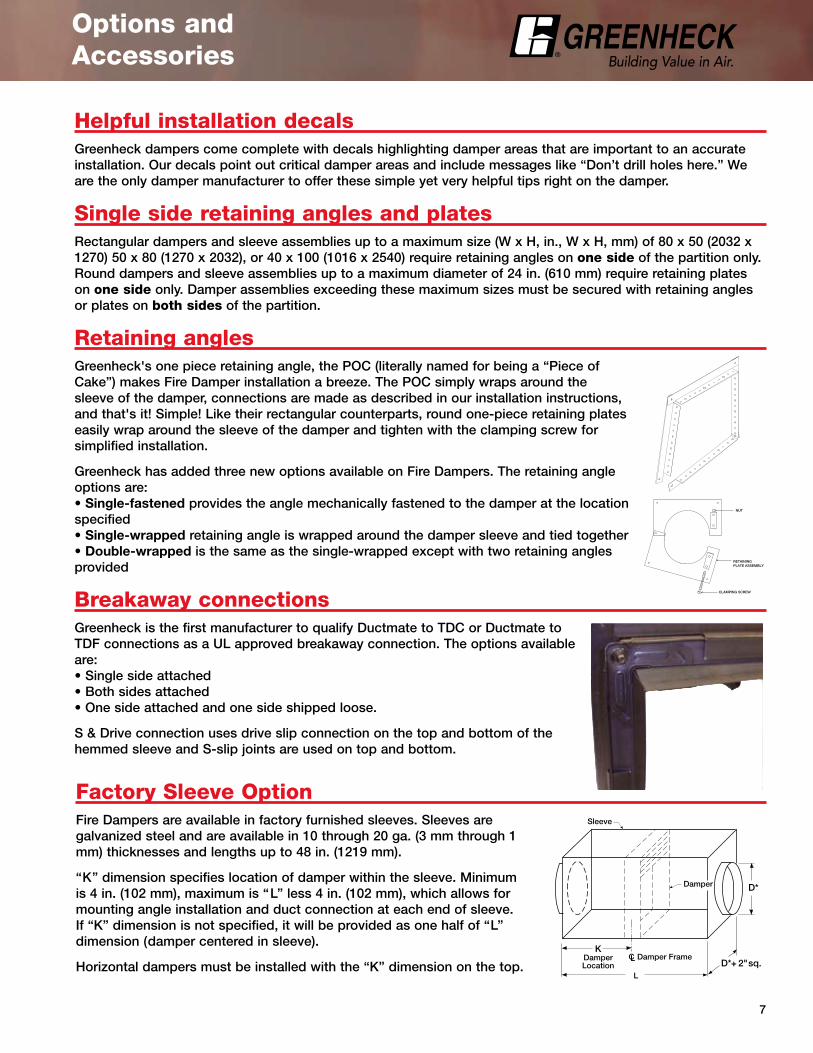
Factory Sleeve OptionFire Dampers are available in factory furnished sleeves. Sleeves are galvanized steel and are available in �0 through 20 ga. (3 mm through � mm) thicknesses and lengths up to 48 in. (�2�9 mm).
“K” dimension specifies location of damper within the sleeve. Minimum is 4 in. (�02 mm), maximum is “L” less 4 in. (�02 mm), which allows for mounting angle installation and duct connection at each end of sleeve. If “K” dimension is not specified, it will be provided as one half of “L” dimension (damper centered in sleeve).
Horizontal dampers must be installed with the “K” dimension on the top. K
DamperLocation
L
CL Damper Frame
Sleeve
Damper D*
D* + 2" sq.
®

8
Pressure loss through an open damper (change in pressure) is a performance criteria required to appropriately select and apply a fire life safety damper in an HVAC system.
Any damper’s pressure loss depends on where and how the damper is installed in the HVAC system. AMCA Standard 500-D defines several configurations to be used for testing damper pressure drop. Greenheck has tested its dampers for pressure loss in the three test figures shown and provides data for each.
Actual pressure loss found in any HVAC system is a combination of many factors. This pressure loss information, along with an analysis of other system influences, should be used to estimate actual pressure losses for a damper installed in a given HVAC system.
D=Duct lengthW=Damper widthH=Damper height
Pressure LossPressure Loss testing was conducted in accordance with AMCA Standard 500-D. All data has been corrected to represent standard air at a density of 0.075 lb/ft3 (�.2 kg/m3).
Damper Performance Testing Criteria
Greenheck Fan Corp. certifies that the models DFD-2�0, DFD-230, DFDTF-2�0, SEDFD-2�0, and SSDFD-2�0 shown herein are licensed to bear the AMCA Seal. The ratings shown are based on tests and procedures performed in accordance with AMCA Publication 5�� and comply with the requirements of the AMCA Certified Ratings Programs. The AMCA Certified Ratings Seal applies to air performance ratings only.
Figure 5.3 illustrates a fully ducted damper.Figure 5.2 illustrates a ducted damper
exhausting air into an open area.Figure 5.5 illustrates a plenum mounted damper.
5D 6D
5D
D 4 (W) (H)3.14
Fig.
5.3
Fig.
5.2
Fig.
5.5
Dimension (in.) 12 x 12 24 x 24 36 x 36 12 x 48 48 x 12
(mm) 305 x 305 610 x 610 914 x 914 305 x 1219 1219 x 305
velocity (fpm) Pressure Drop - in. wg
500 .04 .02 .01 .01 .03
1000 .14 .07 .04 .06 .10
1500 .32 .15 .09 .13 .23
2000 .56 .27 .16 .23 .41
2500 .88 .42 .25 .36 .63
3000 1.26 .61 .36 .52 .91
3500 1.72 .83 .49 .70 1.24
4000 2.24 1.08 .64 .92 1.62
DFD-210, 230, DFDTF-210, SEDFD-210, & SSDFD-210
AMCA Figure 5.2 Pressure Drop
Dimension (in.) 12 x 12 24 x 24 36 x 36 12 x 48 48 x 12
(mm) 305 x 305 610 x 610 914 x 914 305 x 1219 1219 x 305
velocity (fpm) Pressure Drop - in. wg
500 .06 .03 .03 .03 .04
1000 .22 .14 .12 .13 .17
1500 .50 .31 .26 .30 .38
2000 .89 .55 .47 .53 .67
2500 1.39 .86 .73 .83 1.04
3000 2.00 1.24 1.05 1.19 1.50
3500 2.73 1.69 1.42 1.62 2.05
4000 3.56 2.20 1.86 2.11 2.67
DFD-210, 230, DFDTF-210, SEDFD-210, & SSDFD-210
AMCA Figure 5.5 Pressure Drop
Dimension (in.) 12 x 12 24 x 24 36 x 36 12 x 48 48 x 12
(mm) 305 x 305 610 x 610 914 x 914 305 x 1219 1219 x 305
velocity (fpm) Pressure Drop - in. wg
500 .02 .01 .01 .01 .02
1000 .09 .04 .03 .04 .07
1500 .20 .09 .06 .10 .16
2000 .36 .16 .11 .17 .29
2500 .56 .25 .17 .27 .45
3000 .81 .35 .24 .39 .64
3500 1.10 .48 .33 .53 .88
4000 1.44 .63 .42 .70 1.14
DFD-210, 230, DFDTF-210, SEDFD-210, & SSDFD-210
AMCA Figure 5.3 Pressure Drop
Note: Curtain style fire damper pressure drop data is available on www.greenheck.com

9
Model Number Codes
CLOSURE RATINGDFD (dynamic)For use in HVAC systems that are operational in the event of fire.SEDFD 3�6 stainless steel dynamic ratedSSDFD 304 stainless steel dynamic ratedDFDTF Thin frame dynamic ratedDFDAF Airfoil blade dynamic rated
BLADE STYLE2 Fabricated Steel with Triple Vee Reinforcements (3V)3 Fabricated Steel Airfoil Style Blade
FIRE RESISTANCE RATING1 (��⁄2 hour)For use in walls, floors and partitions with fire resistance ratings of less than 3 hours.
3 (3 hour)For use in walls, floors and partitions with fire resistance ratings of 3 hours or more.
PRESSURE RATING0 =Pressure rating up to 4 in wg (996 Pa)
DFD -210
DFD -150X12
FIRE DAMPER MODEL NUMBER CODEThe fire damper model number consists of 5 individual components that make up a specific fire damper's construction. The model number breakdown and corresponding explanation of each component help insure the correct fire damper selection for your application.
CLOSURE RATINGDFD (dynamic)For use in HVAC systems that are operational in the event of fire.ODFD Out of wall dynamic ratedFD (static)For use in HVAC systems that are automatically shut down in the event of fire.OFD Out of wall static rated
PRESSURE RATING0 = Low to MediumSMACNA Pressure Classes up to 2 in. wg (498 Pa)
5 = HighSMACNA Pressure Classes up to 3 in. wg (747 Pa)or higher and Seal Classes A or B
DAMPER WITH INTEGRAL 20 GA. SLEEVE(Economical factory assembled damper with sleeve)X10 = �0 in. long (254 mm)X12 = �2 in. long (304 mm)X14 = �4 in. long (355 mm)X16 = �6 in. long (406 mm)
FIRE RESISTANCE RATING1 (��⁄2 hour)For use in walls, floors, and partitions with fire resistance ratings of less than 3 hours.
3 (3 hour)For use in walls, floors and partitions with fire resistance ratings of 3 hours or more.
FRAME STYLE (depth)0 = Ultrathin - ��⁄2 in. (38 mm)
1 = Narrowline - 2 3⁄�6 in. (56 mm)5 = Standard - 3 ��⁄�6 in. (94 mm)
�
2
3
4
5
� 2 3 4 5
� 2 3 4
�
2
3
4
CLOSURE RATINGCRD (ceiling radiation)For use in ceiling openings with fire resistance ratings of 3 hours or less.
BLADE STYLE1 Rectangular2 Round60 Curtain type
SPECIAL FEATURES LP Low profile X Insulation skirt
B B style
�
2
3
CRD -1LP� 2 3
®
�0
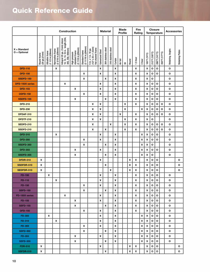
Quick Reference Guide
Accessories
Reta
inin
g Pl
ates
O
O
O
O
O
Reta
inin
g A
ngle
s
O
O
O
O
O
O
O
O
O
O
O
O
O
O
O
O
O
O
O
O
O
O
O
O
O
O
O
O
O
O
O
OClosure
Temperature
350°
F (1
77°C
)
O
O
O
O
O
286°
F (1
41°C
)
O
O
O
O
O
O
O
O
O
O
O
O
O
O
O
O
O
O
O
O
O
O
O
O
O
O
O
O
O
O
O
O
O
212°
F (1
00°C
)
O
O
O
O
O
O
O
O
O
O
O
O
O
O
O
O
O
O
O
O
O
O
O
O
O
O
O
O
O
O
O
O
O
O
O
O
O
165°
F (7
4°C)
X
X
X
X
X
X
X
X
X
X
X
X
X
X
X
X
X
X
X
X
X
X
X
X
X
X
X
X
X
X
X
X
X
X
X
X
X
Fire Rating
3 ho
ur
X
X
X
X
X
X
X
X
X
X
X
X
1.5
hour
X
X
X
X
X
X
X
X
X
X
X
X
X
X
X
X
X
X
X
X
X
X
X
X
X
BladeProfile
Roun
d
X
X
X
X
X
3V
X
X
X
X
X
Air f
oil
X
Curt
ain
X
X
X
X
X
X
X
X
X
X
X
X
X
X
X
X
X
X
X
X
X
X
X
X
X
XMaterial
316
stai
nles
s st
eel
X
X
304
stai
nles
s st
eel
X
X
X
X
X
X
X
X
X
X
X
Galv
aniz
ed S
teel
X
X
X
X
X
X
X
X
X
X
X
X
X
X
X
X
X
X
X
X
X
X
X
X
Construction
5 in
. x 1
in. 1
6 ga
.(1
27 x
25
x 1.
5mm
) Ha
t cha
nnel
fram
e
X
X
X
X
X
X
Stan
dard
fram
e (3
11/
16 in
.)(94
mm
)
X
X
X
X
X
X
X
X
X
X
High
pre
ssur
e st
anda
rd fr
ame
(3 1
1/6
in.)(
94m
m)
X
X
X
X
X
X
X
X
Inte
gral
20
ga. (
1mm
) sle
eve
10
, 12,
14,
16
in.
leng
th (2
54,
305,
356
, 406
mm
)
X
X
Narr
owlin
e fr
ame
(2 3
/16
in.)(
56m
m)
X
X
X
X
Ultr
athi
n fr
ame
(1 1
/2 in
.)(38
mm
)
X
X
Roun
d fr
ame
(20
ga.)(
1mm
)
X
X
X
X
X
X = StandardO = Optional
DFD-110
DFD-150
SSDFD-150
DFD-150X series
DFD-155
ODFD-150
SSDFD-155
DFD-210
DFD-230
DFDAF-310
DFDTF-210
SEDFD-210
SSDFD-210
DFD-310
DFD-350
SSDFD-350
DFD-355
SSDFD-355
DFDR-510
SSDFDR-510
SEDFDR-510
FD-100
FD-110
FD-150
SSFD-150
FD-150X series
FD-155
SSFD-155
OFD-150
FD-300
FD-310
FD-350
SSFD-350
FD-355
SSFD-355
FDR-510
SSFDR-510

��
Model and SizeLimitations
Static Fire Dampers
Model Mounting Horizon-tal or Vertical(H or V)
Maximum Single Section Size W X H, in. (mm) Maximum Multi Section W x H, in. (mm)
No Transitionsor
A style
B C & CO CR R A B C & CO
0 in. offset
1 in. offset
2 in. offset
1.5
Hour
FD-100 V 48 x 48(1219 x 1219)
48 x 40(1219 x 1016)
--- --- --- ---
FD-110 H or V 48 x 48(1219 x 1219)
48 x 43(1219 x 1092)
--- --- --- ---
FD-150
H or V
48 x 48(1219 x 1219)
48 x 43(1219 x 1092)
46 x 42(1168 x 1067)
42(1067)
30(762)
47 (1194)
46 (1168)
96 x 48 or 120 x 40
(2438 x 1219) or
(3048 x 1016)
96 x 43 or 120 x 35
(2438 x 1092) or
(3048 x 889)
94 x 42 or 118 x 34
(2438 x 1067) or
(2997 x 864)
V 48 x 48(1219 x 1219)
48 x 43(1219 x 1092)
46 x 42(1168 x 1067)
68(1727)
30(762)
73(1854)
72(1829)
74 x 74(1880 x 1880)
74 x 69(1880 x 1753)
72 x 69(1829 x 1753)
FD-150X10FD-150X12FD-150X14FD-150X16
H or V
48 x 48(1219 x 1219)
48 x 43(1219 x 1092)
46 x 42(1168 x 1067)
42(1067)
30(762)
47(1194)
46(1168)
96 x 48 or 120 x 40
(2438 x 1219) or
(3048 x 1016)
96 x 43 or 120 x 35
(2438 x 1092) or
(3048 x 889)
---
SSFD-150
H 36 x 36(914 x 914)
36 x 32(914 x 813)
34 x 31(864 x 787)
31(787)
30(762)
35(889)
34(864)
---
V 48 x 48(1219 x 1219)
48 x 43(1219 x 1092)
46 x 42(1168 x 1067)
42(1067)
30(762)
47(1194)
46(1168)
96 x 48 or 120 x 40
(2438 X 1219) or
(3048 x 1016)
96 x 43 or 120 x 35
(2438 x 1092)or
(3048 x 889)
94 x 42 or 118 x 34
(2438 x 1067) or
(2997 x 864)
FD-155
H or V --- --- 46 x 42 (1168 x 1067)
42(1067)
30(762)
47 (1194)
46(1168)
--- --- 96 x 42 or 118 x 34
(2438 x 1067) or
(2997 x 864)
V --- --- 46 x 42(1168 X 1067)
68(1727)
30(762)
73(1854)
72(1829)
--- --- 72 x 69(1829 x 1753)
SSFD-155
H --- --- 34 x 31(864 x 787)
31(787)
30(762)
35 (889)
34(964)
--- --- ---
V --- --- 46 x 42(1168 x 1067)
42(1067)
30(762)
47(1194)
46(1168)
--- --- 96 x 42 or118 x 34
(2438 x 1067) or
(2997 x 864)
OFD-150 H or V 36 x 36(914 x 914)
--- --- --- --- ---
FDR-510 H or V 24 (610) --- --- --- --- ---
SSFDR-510 H or V 24 (610) --- --- --- --- ---
3 ho
ur
FD-300 V 48 x 48(1219 x 1219)
48 x 40(1219 x 1016)
--- --- --- --- --- --- --- ---
FD-310 V 48 x 48(121 9 x 1219)
48 x 43(1219 x 1092)
--- --- --- --- --- --- --- ---
FD-350
H 40 x 40(1016 x 1016)
40 x 35(1016 x 889)
38 x 34(965 x 864)
34(864)
30(762)
39(991)
38(965)
80 x 40(2032 x 1016)
80 x 35(2032 x 889)
78 x 34(1981 x 864)
V 48 x 48(1219 x 1219)
48 x 43(1219 x 1092)
46 x 42(1168 x 1067)
42(1067)
30(762)
47(1194)
46(1168)
--- --- ---
FD-355
H --- --- 38 x 34(965 x 864)
34(864)
30(762)
39(991)
38(965)
--- --- 78 x 34(1981 x 864)
V --- --- 46 x 42(1168 x 1067)
42(1067)
30(762)
47(1194)
46(1168)
--- --- ---
SSFD-350 V 48 x 48(1219 x 1219)
48 x 43(1219 x 1092)
46 x 42(1168 x 1067)
42(1067)
30(762)
47(1194)
46(1168)
--- --- --
SSFD-355 V --- --- 46 x 42(1168 x 1067)
42(1067)
30(762)
47(1194)
46(1168)
--- --- ---
®
�2
Model and SizeLimitations
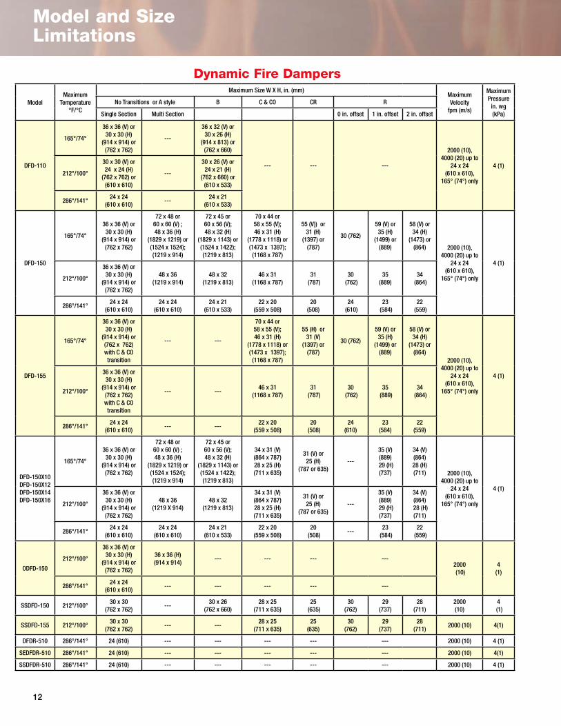
Dynamic Fire Dampers
ModelMaximum
Temperature°F/°C
Maximum Size W X H, in. (mm)Maximum Velocity
fpm (m/s)
Maximum Pressure
in. wg (kPa)
No Transitions or A style B C & CO CR R
Single Section Multi Section 0 in. offset 1 in. offset 2 in. offset
DFD-110
165°/74°
36 x 36 (V) or 30 x 30 (H)
(914 x 914) or(762 x 762)
---
36 x 32 (V) or 30 x 26 (H)
(914 x 813) or(762 x 660)
--- --- ---
2000 (10), 4000 (20) up to
24 x 24(610 x 610),
165° (74°) only
4 (1)212°/100°
30 x 30 (V) or 24 x 24 (H)
(762 x 762) or(610 x 610)
---
30 x 26 (V) or 24 x 21 (H)
(762 x 660) or(610 x 533)
286°/141°24 x 24
(610 x 610)---
24 x 21(610 x 533)
DFD-150
165°/74°
36 x 36 (V) or 30 x 30 (H)
(914 x 914) or(762 x 762)
72 x 48 or60 x 60 (V) ;48 x 36 (H)
(1829 x 1219) or (1524 x 1524);(1219 x 914)
72 x 45 or 60 x 56 (V); 48 x 32 (H)
(1829 x 1143) or (1524 x 1422); (1219 x 813)
70 x 44 or58 x 55 (V); 46 x 31 (H)
(1778 x 1118) or (1473 x 1397); (1168 x 787)
55 (V)) or 31 (H)
(1397) or (787)
30 (762)
59 (V) or 35 (H)
(1499) or (889)
58 (V) or 34 (H)
(1473) or (864) 2000 (10),
4000 (20) up to 24 x 24
(610 x 610), 165° (74°) only
4 (1)
212°/100°
36 x 36 (V) or 30 x 30 (H)
(914 x 914) or(762 x 762)
48 x 36(1219 x 914)
48 x 32(1219 x 813)
46 x 31(1168 x 787)
31 (787)
30 (762)
35 (889)
34 (864)
286°/141°24 x 24
(610 x 610)24 x 24
(610 x 610)24 x 21
(610 x 533)22 x 20
(559 x 508)20
(508)24
(610)23
(584)22
(559)
DFD-155
165°/74°
36 x 36 (V) or 30 x 30 (H)
(914 x 914) or (762 x 762)with C & CO transition
--- ---
70 x 44 or58 x 55 (V); 46 x 31 (H)
(1778 x 1118) or (1473 x 1397); (1168 x 787)
55 (H) or 31 (V)
(1397) or (787)
30 (762)
59 (V) or 35 (H)
(1499) or (889)
58 (V) or 34 (H)
(1473) or (864)
2000 (10), 4000 (20) up to
24 x 24(610 x 610),
165° (74°) only
4 (1)
212°/100°
36 x 36 (V) or 30 x 30 (H)
(914 x 914) or(762 x 762)with C & CO transition
--- ---46 x 31
(1168 x 787)31
(787)30
(762)35
(889)34
(864)
286°/141°24 x 24
(610 x 610)--- ---
22 x 20(559 x 508)
20 (508)
24 (610)
23 (584)
22 (559)
DFD-150X10DFD-150X12DFD-150X14DFD-150X16
165°/74°
36 x 36 (V) or 30 x 30 (H)
(914 x 914) or (762 x 762)
72 x 48 or60 x 60 (V) ;48 x 36 (H)
(1829 x 1219) or (1524 x 1524);(1219 x 914)
72 x 45 or 60 x 56 (V); 48 x 32 (H)
(1829 x 1143) or (1524 x 1422); (1219 x 813)
34 x 31 (V)(864 x 787)28 x 25 (H)(711 x 635)
31 (V) or 25 (H)
(787 or 635)---
35 (V)(889)
29 (H)(737)
34 (V)(864)28 (H)(711) 2000 (10),
4000 (20) up to 24 x 24
(610 x 610), 165° (74°) only
4 (1)
212°/100°
36 x 36 (V) or 30 x 30 (H)
(914 x 914) or (762 x 762)
48 x 36(1219 X 914)
48 x 32(1219 x 813)
34 x 31 (V)(864 x 787)28 x 25 (H)(711 x 635)
31 (V) or 25 (H)
(787 or 635)---
35 (V)(889)
29 (H)(737)
34 (V)(864)
28 (H)(711)
286°/141°24 x 24
(610 x 610)24 x 24
(610 x 610)24 x 21
(610 x 533)22 x 20
(559 x 508)20
(508)---
23 (584)
22 (559)
ODFD-150
212°/100°
36 x 36 (V) or 30 x 30 (H)
(914 x 914) or (762 x 762)
36 x 36 (H)(914 x 914)
--- --- --- ---2000 (10)
4 (1)
286°/141°24 x 24
(610 x 610)--- --- --- --- ---
SSDFD-150 212°/100°30 x 30
(762 x 762)---
30 x 26(762 x 660)
28 x 25(711 x 635)
25 (635)
30(762)
29(737)
28(711)
2000 (10)
4 (1)
SSDFD-155 212°/100°30 x 30
(762 x 762)--- ---
28 x 25(711 x 635)
25(635)
30(762)
29(737)
28(711)
2000 (10) 4(1)
DFDR-510 286°/141° 24 (610) --- --- --- --- --- 2000 (10) 4 (1)
SEDFDR-510 286°/141° 24 (610) --- --- --- --- --- 2000 (10) 4(1)
SSDFDR-510 286°/141° 24 (610) --- --- --- --- --- 2000 (10) 4 (1)

�3
Model and SizeLimitations
Multi Blade Dynamic Fire Dampers
Model
Maximum Sizes H or V Installation inches (mm)
Maximum Velocity fpm (m/s)
Maximum Pressurein. wg (kPa)
No TransitionsC & O
R
Single Section Size Multi Section 0 in. offset 1 in. offset 2 in. offset
DFD-210
36 X 36 up to 350°F(914 X 914)
32 X 50 up to 212°F(813 X 1270)
64 X 50 up to 212°F(1626 X 1270)
62 X 48 up to 212°F(1575 X 1219)
30 (762) 48 (1219) 48 (1219)
2000 up to 64 x 50(10 up to 1626 X 1270)
4000 up to 32 x 50(20 up to 813 X 1270)
10 (2.5)
DFDTF-210
32 x 48 (H)(813 x 1219) 32 x 50 (V)
(813 x 1219)
96 X 72(2438 X 1829) or
32 x 96(813 x 2438)
94 X 70(2388 X 1778)
30 (762) 71 (1803) 70 (1778) 2000 (10) 4 (1)
64 X 50 (V)(1626 X 1270) 64 X 48 (H)
(1626 X 1219)
62 X 48 (V) (1575 X 1219)
62 X 46 (H)(1575 X 1168)
30 (762)
47 (V)(1194)45 (H)(1143)
46 (V)(1168)44 (H)(1118)
4000 (20) 8 (2)
SSDFD-210 24 X 30(610 X 762)
48 X 30(1219 X 762)
46 X 28(1168 X 711)
30 (762) 29 (737) 28 (711) 2000 (10)4 (1)
SEDFD-210 24 X 30(610 X 762)
48 X 30(1219 X 762)
46 X 28(1168 X 711)
30 (762) 29 (737) 28 (711) 2000 (10)4 (1)
DFDAF-310
32 X 50(813 X 1219)
96 X 50(2438 X 1219)
62 X 48(1575 X 1219)
30 (762) 48 (1219) 48 (1219) 2000 (10)4 (1)
32 X 50(813 X 1219)
---30 X 48
(762 X 1219)30 (762) 48 (1219) 48 (1219) 4000 (20)
4 (1)
DFD-230
36 X 36 (914 X 914) or
32 X 48(813 X 1219)
64 X 48(1626 X 1219)
62 X 46(1575 X 1168)
30 (762) 47 (1194) 46 (1168) 2000 (10) 4 (1)
---30 X 46
(762 x 1168)30
(762)31
(787)30
(762)4000 (10) 10 (2.5)
Model Maximum Temperature
°F/°C
Maximum Size W X H, in. (mm) Maximum Velocity
fpm (m/s)
Maximum Pressure
in. wg (kPa)
No Transitions or A style B C & CO CR R
Single Section Multi Section 0 in. offset 1 in. offset 2 in. offset
DFD-310
165°/74°36 x 36
(914 x 914)
---
36 x 32(914 x 813
--- --- ---
2000 (10), 4000 (20) up to
24 x 24(610 x 610),
165° (74°) only
4 (1)212°/10030 x 30
(762 x 762)30 X 26
(762 x 660)
286°/141°24 x 24
(610 x 610)24 x 21
(610 x 533)
DFD-350
165°/74°
36 x 36 (V) or 30 x 30 (H)
(914 x 914) or(762 x 762)
48 x 48 (V) or 48 x 36 (H)
(1219 x 1219) or(1219 x 914)
48 x 45 (V) or 48 x 32 (H)
(1219 x 1143) or (1219 x 813)
46 x 44 (V) or 46 x 31 (H)
(1168 x 1118) or(1168 x 787)
44 (V) or 31 (H)
(1118 or 787)
30(762)
47 (V) or 35 (H)
(1194) or(889)
46 (V) or 34 (H)
(1168) or (864) 2000 (10),
4000 (20) up to 24 x 24
(610 x 610), 165° (74°) only
4 (1)212°/100°
36 x 36 (V) or 30 x 30 (H)
(914 x 914) or(762 x 762)
48 x 36(1219 x 914)
48 x 32(1219 x 813)
46 x 31(1168 x 787)
31 (787)
30 (762)
35 (889)
34(864)
286°/141°24 x 24
(610 x 610)---
24 x 21(610 x 533)
22 x 20(559 x 508)
20 (508)
24(610)
23(584)
22(559)
DFD-355
165°/74°
36 x 36 (V) or 30 x 30 (H)
(914 x 914) or(762 x 762)
48 x 48 (V) or 48 x 36 (H)
(1219 x 1219) or(1219 x 914)
48 x 45 (V) or 48 x 32 (H)
(1219 x 1143) or (1219 x 813)
46 x 44 (V) or 46 x 31 (H)
(1168 x 1118) or(1168 x 787)
44 (V) or 31 (H)
(1118 or 787)
30(762)
47 (V) or 35 (H)
(1194) or(889)
46 (V) or 34 (H)
(1168) or (864)
2000 (10), 4000 (20) up to
24 x 24(610 x 610),
165° (74°) only
4 (1)212°/100°
30 x 30(762 x 762)
48 x 36(1219 x 914)
48 x 32(1219 x 813)
46 x 31(1168 x 787)
31(787)
30(762)
35(889)
34(864)
286°/141°24 x 24
(610 x 610)24 x 24
(610 x 610)24 x 21
(610 x 533)22 x 20
(559 x 508)20
(508)24
(610)23
(584)22
(559)
SSDFD-350 212°/100°30 x 30
(762 x 762)---
30 x 26(762 x 660)
28 x 25(711 x 635)
25(635)
30(762)
29(737)
28(711)
2000 (10) 4 (1)
SSDFD-355 212°/100°30 x 30
(762 x 762)--- ---
28 x 25(711 x 635)
25(635)
30(762)
29(737)
28(711)
2000 (10) 4 (1)
Dynamic Fire Dampers continued
®

�4
Codes/Listings/Approvals
Test Standards & CertificationsUL555
This standard governs fire dampers which are intended for use where air ducts penetrate or terminate at openings in walls or partitions, in air transfer openings in partitions, and where air ducts extend through floors as specified in the Standard for Installation of Air-Conditioning and Ventilating Systems, NFPA 90A. In a fire emergency the fire damper is designed to close and prevent the spread of fire from one side of the wall or partition to the other. Testing includes cycling, salt spray, dust loading, dynamic closure, fire endurance, and hose stream.
UL555CThis standard governs ceiling dampers which are intended for use in air handling duct outlets which penetrate membrane ceilings of hourly fire rated resistive assemblies, or for installation in the ceiling membrane of such assemblies which utilize the plenum space for return air.
AMCAThe AMCA Certified Rating Program seal assures you that a product line has been tested to the appropriate AMCA standards in accordance with a legal license agreement and that the manufacturer's catalogued certified ratings have been submitted to the AMCA staff for approval prior to publication.
Warnock HerseyThe Warnock Hersey is among the most well-recognized and respected North American marks of compliance for building codes, association criteria, and product safety and performance standards. Warnock Hersey, like UL, is an independent agency which evaluates and tests products to recognized standards including those dictated by UL, NFPA, and ASTM.
CodesIn addition to the UL, AMCA, California State Fire Marshal and New York MEA, Greenheck fire and ceiling radiation products meet requirements established by:National Fire Protection Association (NFPA Standards 90A, 92A, 92B and �0�)BOCA National Building Codes SBCCI Standard Building codes IBC International Building CodesICBO Uniform Building Codes ICC International Code Council
Greenheck Fan Corp. certifies that the models DFD-2�0, DFD-230, DFDTF-2�0, SEDFD-2�0, and SSDFD-2�0 shown herein are licensed to bear the AMCA Seal. The ratings shown are based on tests and procedures performed in accordance with AMCA Publication 5�� and comply with the requirements of the AMCA Certified Ratings Programs. The AMCA Certified Ratings Seal applies to air performance ratings only.
456935
COMBINATION FIRE/SMOKE DAMPERS
DFD, FSD, SSDFD, SSFSD,ODFD, OFSD, OSSDFD, OSSFSD
Greenheck Fan Corporation
#3230-0981:110NYC MEA #260-91-MComplies with UBC
CSFM Listing #3225-0981:103
#3225-0981:109#3230-0981:104
SERIES COMBINATIONFIRE/SMOKE DAMPERS
GREENHECK FANP/N 456935
JOB# 86767H:/WIP/LINDAWIP/420-6767
7/24/97
FIRE/SMOKE DAMPERSSERIES COMBINATION
#3230-0981:104#3225-0981:109
CSFM Listing #3225-0981:103
Complies with UBC NYC MEA #260-91-M
#3230-0981:110
Greenheck Fan Corporation
ODFD, OFSD, OSSDFD, OSSFSDDFD, FSD, SSDFD, SSFSD,
COMBINATION FIRE/SMOKE DAMPERS
456935
200%
Listings / Approvals
UL Category
California State Fire Marshal
New York City MEA
(all models)
EMME
DFD-2xx 3225-098�:�03
R�33�7 All DFD / FD (� �/2 hour) 3225-098�:�02
All DFD / FD (3 hour) 3225-098�:�07 260-9�-M CABS CRD-� / CRD-2 3226-0987:�0� R�3446 CRD-60 3226-098�:���

�5
Static Fire Damper Specification Checklist√ UL Standard – UL 555 Classified
√ Fire Resistance – NFPA 90A & �0� required • ��⁄2 hour (less than 3 hours) • 3 hours (3 hours or more)
√ Fire Closure Temperature – �65º F (73º C), 2�2º F (�00º C), 286º F (�4�º C) available
√ Damper Construction – Frame, Blades
√ Sleeves – Single assembly with an integral factory sleeve of desired lengths and thickness.
√ Retaining Angles or Plates – UL listed angles (rectangular dampers) or plates (round dampers)
√ Mounting – Vertical or horizontal mount.
√ Accessories – Security Bar
Dynamic Fire Damper Specification Checklist√ UL Standard – UL 555 Classified
√ Fire Resistance – NFPA 90A & �0� required • ��⁄2 hour (less than 3 hours) • 3 hours (3 hours or more)
√ Fire Closure Temperature – �65º F (74º C), 2�2º F (�00º C), 286º F (�4�º C) available. For multi-blade DFD’s 350º F (�77º C) is also available
√ Differential Pressure – Maximum pressure across closed damper (4, 6, 8, or �0 in. wg [� kPa, �.5 kPa, 2 kPa, 2.5 kPa])
√ Velocity – Maximum airflow rate through the open damper (up to 4000 fpm [20 m/s])
√ Damper Construction – Frame, Blades, Blade Stops, Jamb Seal only, Linkage, Axles
√ Sleeves – Single assembly with an integral factory sleeve of desired lengths and thickness.
√ Retaining Angles or Plates – UL listed angles (rectangular dampers) or plates (round dampers)
√ Mounting – Vertical or horizontal mount
√ Accessories – Security Bars
Ceiling Radiation Damper Specification Checklist√ UL Standard – UL555C Classified
√ Fire Resistance – NFPA 90A & �0� required • ��⁄2 hour (less than 3 hours)
√ Damper Construction – Frame, Blades
√ Frame options – Standard, Bottom Extension, Top Extension, Bottom & Top extension
√ Accessories – Volume Controller
Please visit our website at www.greenheck.com/products/dampers/index for complete specifications.
Specification Checklist®

The Greenheck Difference
Greenheck warrants this equipment to be free from defects in material and workmanship for a period of one year from the purchase date. Any units or parts which prove defective during the warranty period will be replaced at our option when returned to our factory, transportation prepaid. Motors are warranted by the motor manufacturer for a period of one year. Should motors furnished by Greenheck prove defective during this period, they should be returned to the nearest authorized motor service station. Greenheck will not be responsible for any removal or installation costs.As a result of our commitment to continuous improvement, Greenheck reserves the right to change specifications without notice.
P.O. Box 410 • Schofield, WI 54476-0410 • Phone (715) 359-6171 • greenheck.comDFD FD CRD Rev. 2 December 2005 SNCopyright © 2005 Greenheck Fan Corp.
Our Warranty
Greenheck has a complete line of Dampersfor your needs!• Commercial Control• Industrial Control• Fire, Smoke, & Combination Fire Smoke• Ceiling Radiation• Backdraft• Pressure Relief Dampers• Manual Balancing• Access Doors• Marine• Severe Environment• Industrial Smoke• Insulated Thermally Broken • Air Measuring • Pressure Relief Access Doors• Barometric Relief• Industrial Backdraft
For over 50 years, the Greenheck name has been synonymous with innovation, product quality and customer service. We know our dampers are:• Number one in product quality and reliability • Number one in combined reputation and after-sale service and support• Put into service over �50 times a day
From the Petronas Twin Towers in Kuala Lumpur to well-known Las Vegas casinos and world-renowned hospitals, Greenheck dampers meet the safety needs of the most complex applications.