Dynamic Reverse Engineering of Graphical User Interfacesapaiva/PBGT/PBGT_material/IJAS.pdf ·...
13
Dynamic Reverse Engineering of Graphical User Interfaces Inˆ es Coimbra Morgado and Ana C. R. Paiva Department of Informatics Engineering, Faculty of Engineering, University of Porto, rua Dr. Roberto Frias, 4200-465 Porto, Portugal {pro11016, apaiva}@fe.up.pt Jo˜ ao Pascoal Faria Department of Informatics Engineering, Faculty of Engineering, University of Porto rua Dr. Roberto Frias, 4200-465 Porto, Portugal INESC TEC, Porto, Portugal [email protected] Abstract—This paper presents a dynamic reverse engineering approach and a tool, ReGUI, developed to reduce the effort of obtaining models of the structure and behaviour of a software applications Graphical User Interface (GUI). It describes, in more detail, the architecture of the REGUI tool, the process followed to extract information and the different types of models produced to represent such information. Each model describes different characteristics of the GUI. Besides graphical representations, which allow checking visually properties of the GUI, the tool also generates a textual model in Spec# to be used in the context of model based GUI testing and a Symbolic Model Verification model, which enables the verification of several properties expressed in computation tree logic. The models produced must be completed and validated in order to ensure that they faithfully describe the intended behaviour. This validation process may be performed by manually analysing the graphical models produced or automatically by proving properties, such as reachability, through model checking. A feasibility study is described to illustrate the overall approach, the tool and the results obtained. Keywords-ReGUI; Dynamic Reverse Engineering; GUI Testing; Properties Verification; CTL; Model Checking; SMV I. I NTRODUCTION This paper extends the research work presented in [1], which describes a reverse engineering tool to extract a model from the execution of a Graphical User Interface (GUI). In particular, the state of the art is improved and the overall approach is described in more detail. Moreover, a new module was implemented in order to automatically generate a Symbolic Model Verification (SMV) model for model checking. The case study was extended in order to illustrate the additional features. GUI models are key inputs for several advanced techniques, such as Model Based GUI Testing (MBGT) [2], [3], [4], which enables the automatic test case generation, increasing the systematisation and automation of the GUI testing process, and model checking, which enables an automatic verification and validation of some properties of the system. However, the manual construction of such models is a time consuming and error prone activity. One way of diminishing this effort is to automatically construct part of the model by a reverse engineering process. The challenge tackled in this research work is the automatic construction of part of the software’s GUI model (structure and behaviour) using a dynamic reverse engineering technique. The extracted information is presented in several formats that allow performing different types of analysis, such as, visual inspection, model checking and MBGT. The term reverse engineering was firstly defined in 1985 by Rekoff [5] as “the process of developing a set of specifications for a complex hardware system by an orderly examination of specimens of that system”. Five years later, Chikofsky and Cross [6] adapted this definition to software systems: “Reverse Engineering is the process of analysing a subject system to (1) identify the system’s components and interrelationships and (2) to create representations of the system in another form or at a higher level of abstraction”. The origin of software reverse engineering lies on the necessity of improving and automating software maintenance. It is estimated that program comprehension [7], i.e., under- standing the structure and the behaviour of the software, corresponds to over 50% of software maintenance [8]. As such, developing tools which may aid software engineers on this task is of the utmost importance. Reverse engineering has already proved to be useful on this subject. For example, reverse engineering helped coping with the Y2K problem, with the European currency conversion and with the migration of information systems to the web and towards the electronic commerce [9]. For such reasons, the IEEE-1219 standard 1 , which was replaced by the IEEE-14764 one 2 , recommends reverse engineering as a key supporting technology to software maintenance [9]. In the last two decades, reverse engineering tools have evolved considerably and, nowadays, reverse engineering is useful for other fields of study rather than software main- tenance, such as, software testing and auditing security and vulnerability. According to Canfora et al. [10], nowadays, the main goals of reverse engineering are: • recovering architectures and design patterns; 1 IEEE Standard for Software Maintenance 2 Standard for Software Engineering - Software Life Cycle Processes - Maintenance
Transcript of Dynamic Reverse Engineering of Graphical User Interfacesapaiva/PBGT/PBGT_material/IJAS.pdf ·...
Dynamic Reverse Engineering of Graphical UserInterfaces
Ines Coimbra Morgado and Ana C. R. PaivaDepartment of Informatics Engineering,
Faculty of Engineering, University of Porto,rua Dr. Roberto Frias, 4200-465 Porto, Portugal
{pro11016, apaiva}@fe.up.pt
Joao Pascoal FariaDepartment of Informatics Engineering,
Faculty of Engineering, University of Portorua Dr. Roberto Frias, 4200-465 Porto, Portugal
INESC TEC, Porto, [email protected]
Abstract—This paper presents a dynamic reverse engineeringapproach and a tool, ReGUI, developed to reduce the effort ofobtaining models of the structure and behaviour of a softwareapplications Graphical User Interface (GUI). It describes, in moredetail, the architecture of the REGUI tool, the process followed toextract information and the different types of models producedto represent such information. Each model describes differentcharacteristics of the GUI. Besides graphical representations,which allow checking visually properties of the GUI, the toolalso generates a textual model in Spec# to be used in thecontext of model based GUI testing and a Symbolic ModelVerification model, which enables the verification of severalproperties expressed in computation tree logic. The modelsproduced must be completed and validated in order to ensure thatthey faithfully describe the intended behaviour. This validationprocess may be performed by manually analysing the graphicalmodels produced or automatically by proving properties, suchas reachability, through model checking. A feasibility study isdescribed to illustrate the overall approach, the tool and theresults obtained.
Keywords-ReGUI; Dynamic Reverse Engineering; GUI Testing;Properties Verification; CTL; Model Checking; SMV
I. INTRODUCTION
This paper extends the research work presented in [1], whichdescribes a reverse engineering tool to extract a model from theexecution of a Graphical User Interface (GUI). In particular,the state of the art is improved and the overall approachis described in more detail. Moreover, a new module wasimplemented in order to automatically generate a SymbolicModel Verification (SMV) model for model checking. Thecase study was extended in order to illustrate the additionalfeatures.
GUI models are key inputs for several advanced techniques,such as Model Based GUI Testing (MBGT) [2], [3], [4],which enables the automatic test case generation, increasingthe systematisation and automation of the GUI testing process,and model checking, which enables an automatic verificationand validation of some properties of the system. However,the manual construction of such models is a time consumingand error prone activity. One way of diminishing this effortis to automatically construct part of the model by a reverseengineering process.
The challenge tackled in this research work is the automaticconstruction of part of the software’s GUI model (structureand behaviour) using a dynamic reverse engineering technique.The extracted information is presented in several formats thatallow performing different types of analysis, such as, visualinspection, model checking and MBGT.
The term reverse engineering was firstly defined in 1985 byRekoff [5] as “the process of developing a set of specificationsfor a complex hardware system by an orderly examination ofspecimens of that system”. Five years later, Chikofsky andCross [6] adapted this definition to software systems: “ReverseEngineering is the process of analysing a subject system to (1)identify the system’s components and interrelationships and (2)to create representations of the system in another form or ata higher level of abstraction”.
The origin of software reverse engineering lies on thenecessity of improving and automating software maintenance.It is estimated that program comprehension [7], i.e., under-standing the structure and the behaviour of the software,corresponds to over 50% of software maintenance [8]. Assuch, developing tools which may aid software engineers onthis task is of the utmost importance. Reverse engineeringhas already proved to be useful on this subject. For example,reverse engineering helped coping with the Y2K problem, withthe European currency conversion and with the migration ofinformation systems to the web and towards the electroniccommerce [9]. For such reasons, the IEEE-1219 standard1,which was replaced by the IEEE-14764 one2, recommendsreverse engineering as a key supporting technology to softwaremaintenance [9].
In the last two decades, reverse engineering tools haveevolved considerably and, nowadays, reverse engineering isuseful for other fields of study rather than software main-tenance, such as, software testing and auditing security andvulnerability.
According to Canfora et al. [10], nowadays, the main goalsof reverse engineering are:
• recovering architectures and design patterns;
1IEEE Standard for Software Maintenance2Standard for Software Engineering - Software Life Cycle Processes -
Maintenance
• re-documenting programs and databases;• identifying reusable assets;• building traceability between software artefacts;• computing change impacts;• re-modularising existing systems;• renewing user interfaces;• migrating towards new architectures and platforms;• testing and maintenance.As every technology, reverse engineering techniques can
also be used with malicious intent [11], like removing softwareprotection and limitations or allowing unauthorised accessto systems/data. However, the developers may use the sametechniques in order to assure software’s safety.
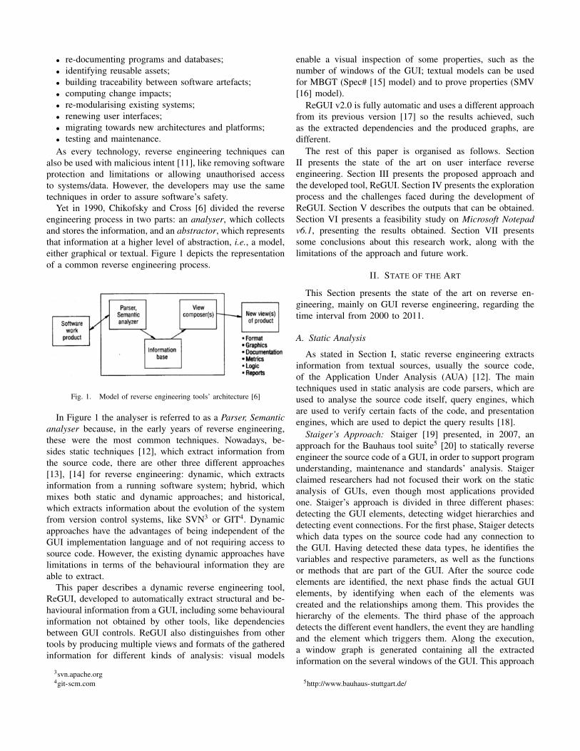
Yet in 1990, Chikofsky and Cross [6] divided the reverseengineering process in two parts: an analyser, which collectsand stores the information, and an abstractor, which representsthat information at a higher level of abstraction, i.e., a model,either graphical or textual. Figure 1 depicts the representationof a common reverse engineering process.
Fig. 1. Model of reverse engineering tools’ architecture [6]
In Figure 1 the analyser is referred to as a Parser, Semanticanalyser because, in the early years of reverse engineering,these were the most common techniques. Nowadays, be-sides static techniques [12], which extract information fromthe source code, there are other three different approaches[13], [14] for reverse engineering: dynamic, which extractsinformation from a running software system; hybrid, whichmixes both static and dynamic approaches; and historical,which extracts information about the evolution of the systemfrom version control systems, like SVN3 or GIT4. Dynamicapproaches have the advantages of being independent of theGUI implementation language and of not requiring access tosource code. However, the existing dynamic approaches havelimitations in terms of the behavioural information they areable to extract.
This paper describes a dynamic reverse engineering tool,ReGUI, developed to automatically extract structural and be-havioural information from a GUI, including some behaviouralinformation not obtained by other tools, like dependenciesbetween GUI controls. ReGUI also distinguishes from othertools by producing multiple views and formats of the gatheredinformation for different kinds of analysis: visual models
3svn.apache.org4git-scm.com
enable a visual inspection of some properties, such as thenumber of windows of the GUI; textual models can be usedfor MBGT (Spec# [15] model) and to prove properties (SMV[16] model).
ReGUI v2.0 is fully automatic and uses a different approachfrom its previous version [17] so the results achieved, suchas the extracted dependencies and the produced graphs, aredifferent.
The rest of this paper is organised as follows. SectionII presents the state of the art on user interface reverseengineering. Section III presents the proposed approach andthe developed tool, ReGUI. Section IV presents the explorationprocess and the challenges faced during the development ofReGUI. Section V describes the outputs that can be obtained.Section VI presents a feasibility study on Microsoft Notepadv6.1, presenting the results obtained. Section VII presentssome conclusions about this research work, along with thelimitations of the approach and future work.
II. STATE OF THE ART
This Section presents the state of the art on reverse en-gineering, mainly on GUI reverse engineering, regarding thetime interval from 2000 to 2011.
A. Static Analysis
As stated in Section I, static reverse engineering extractsinformation from textual sources, usually the source code,of the Application Under Analysis (AUA) [12]. The maintechniques used in static analysis are code parsers, which areused to analyse the source code itself, query engines, whichare used to verify certain facts of the code, and presentationengines, which are used to depict the query results [18].
Staiger’s Approach: Staiger [19] presented, in 2007, anapproach for the Bauhaus tool suite5 [20] to statically reverseengineer the source code of a GUI, in order to support programunderstanding, maintenance and standards’ analysis. Staigerclaimed researchers had not focused their work on the staticanalysis of GUIs, even though most applications providedone. Staiger’s approach is divided in three different phases:detecting the GUI elements, detecting widget hierarchies anddetecting event connections. For the first phase, Staiger detectswhich data types on the source code had any connection tothe GUI. Having detected these data types, he identifies thevariables and respective parameters, as well as the functionsor methods that are part of the GUI. After the source codeelements are identified, the next phase finds the actual GUIelements, by identifying when each of the elements wascreated and the relationships among them. This provides thehierarchy of the elements. The third phase of the approachdetects the different event handlers, the event they are handlingand the element which triggers them. Along the execution,a window graph is generated containing all the extractedinformation on the several windows of the GUI. This approach
5http://www.bauhaus-stuttgart.de/
was intended for C/C++ applications with a GUI implementedwith GUI libraries, such as GTK6 or Qt7.
Lutteroth’s Approach: Lutteroth [21] presented, in 2008,an approach whose goal was to automatically improve thelayout of hard-coded GUIs. The approach extracts the GUI’sstructure and transforms it into a formal layout, AucklandLayout Model (ALM), which was defined by Lutteroth andWeber [22] in 2006. This approach extracts the structure of theGUI, by identifying its root element and navigating throughits descendants. During this process, the position of each ofthe elements is mapped to a tabstop, which is a ALM propertythat represents a position in the coordinate system of a GUI.
Afterwards, the properties of each element, such as sizeand position, are updated, according to what best fits the GUI.For example, if an element has static content, a button forinstance, then its size remains unaltered; otherwise, the bestsize is calculated according to its possible contents. In theend, the obtained layout may even be automatically improved.This may be done, for example, with the aid of some layoutstandards.
GUISurfer: In 2010, Silva et al. [23] developed theGUISurfer framework to test GUI-based Java applications, byfollowing a static reverse engineering approach. The frame-work is composed by three tools: File Parser, ASTAnalyser andGraph. The first tool is responsible for the reverse engineeringprocess, by parsing the GUI’s source code and extractingbehavioural information into an Abstract Syntax Tree (AST)[24]. Then, the second tool slices the information contained inthe AST, focusing on the interface layer. In order to do so, theASTAnalyser requires, besides the AST, the entry point of theapplication (the main method) and the set of GUI elements,which are part of the slicing process. In the end of this secondphase, two files are generated: one containing the initial stateof the GUI and one containing the events that may occurfrom the initial state. The third tool processes these two filesand generates two Haskell specification files, which map thedifferent events and conditions to actions on the GUI.
B. Dynamic Analysis
This Section describes existing dynamic reverse engineeringapproaches without and with code instrumentation.
1) Approaches Without Instrumentation:GUIRipper: In 2003, Memon et al. [25] presented GUIRip-
per, a dynamic reverse engineering tool, which extracts be-havioural information from the GUI of Java systems for testingpurposes [26].
GUIRipper automatically interacts with the system’s GUI,attempting to open as many windows as it can and, duringthis process, it extracts the GUI’s structure and behaviour,producing three different artefacts. The GUI Forest is a graphrepresenting the structure of the GUI. Each node represents awindow of the GUI, containing the structure of its elements;an edge from a node a to a node b indicates that the window
6www.gtk.org7qt.digia.com/
represented by the node b is accessible from the windowrepresented by the node a. The second artefact is an eventflow graph (EFG), which represents the behaviour of the GUI.Each node represents an event, such as click on the buttonOK; an edge from a node a to a node b indicates event b canfollow event a. The third artefact is an integration tree, whichrelates the different components of the GUI. This last artefactis necessary to rip off the GUI into several components,generating EFGs for each one.
Amalfitano et al.’s Approach: Amalfitano et al.’s [27]presented, in 2008, an approach to reverse engineer Ajax[28] based Rich Internet Applications (RIAs) [29] as theyclaimed the problematic of modelling and validating thistype of applications had not yet been explored thoroughly.They intended to fill this gap by dynamically extracting thebehaviour of an application and representing it as a finite statemachine (FSM) [30].
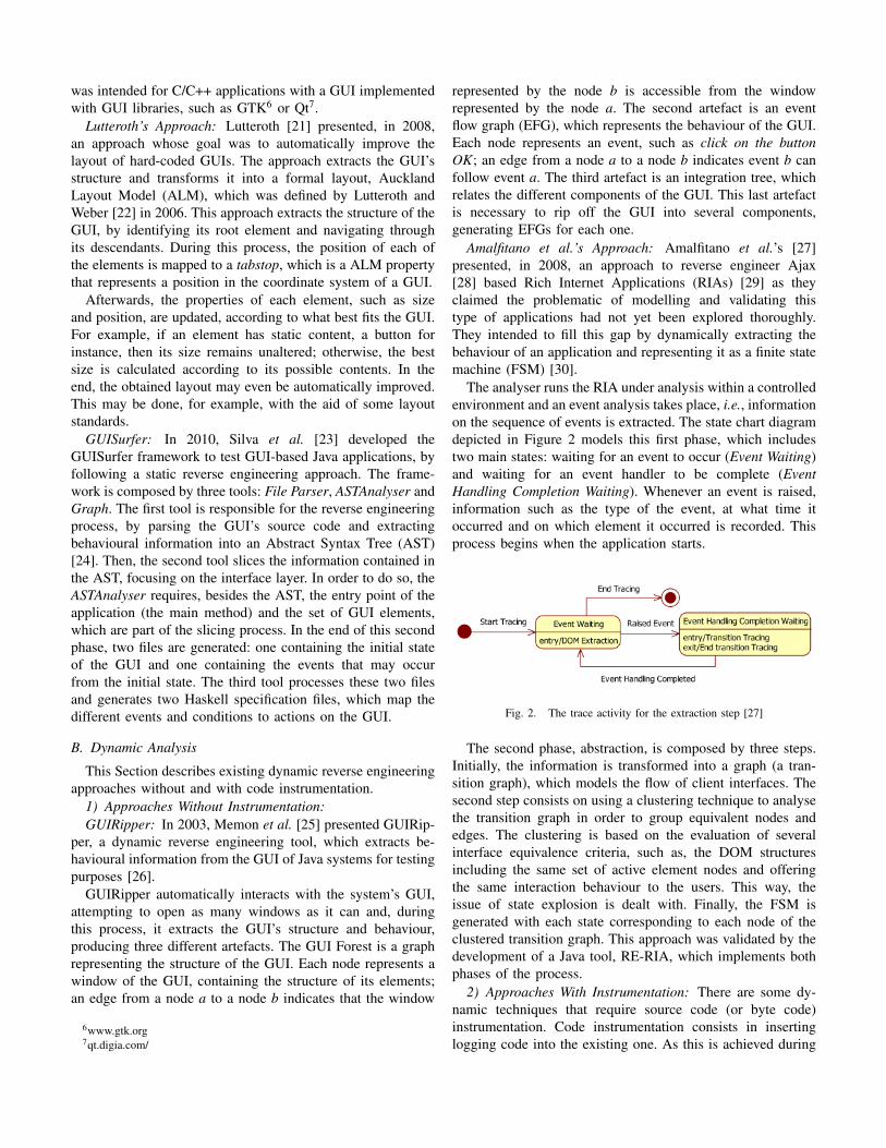
The analyser runs the RIA under analysis within a controlledenvironment and an event analysis takes place, i.e., informationon the sequence of events is extracted. The state chart diagramdepicted in Figure 2 models this first phase, which includestwo main states: waiting for an event to occur (Event Waiting)and waiting for an event handler to be complete (EventHandling Completion Waiting). Whenever an event is raised,information such as the type of the event, at what time itoccurred and on which element it occurred is recorded. Thisprocess begins when the application starts.
Fig. 2. The trace activity for the extraction step [27]
The second phase, abstraction, is composed by three steps.Initially, the information is transformed into a graph (a tran-sition graph), which models the flow of client interfaces. Thesecond step consists on using a clustering technique to analysethe transition graph in order to group equivalent nodes andedges. The clustering is based on the evaluation of severalinterface equivalence criteria, such as, the DOM structuresincluding the same set of active element nodes and offeringthe same interaction behaviour to the users. This way, theissue of state explosion is dealt with. Finally, the FSM isgenerated with each state corresponding to each node of theclustered transition graph. This approach was validated by thedevelopment of a Java tool, RE-RIA, which implements bothphases of the process.
2) Approaches With Instrumentation: There are some dy-namic techniques that require source code (or byte code)instrumentation. Code instrumentation consists in insertinglogging code into the existing one. As this is achieved during

run time and without access to the code, they are considereddynamic approaches instead of hybrid ones.
Briand et al.’s Approach: Briand et al. proposed, in 2006[31], an approach to dynamically extract behavioural informa-tion from Java distributed communications, namely RemoteMethod Invocation applications. The extracted information isrepresented as UML sequence diagrams. Even though theremay be several applications to these diagrams, they intendedto test the consistency of the code with the design.
Briand et al. divided their approach in two phases. The firstphase consists in the instrumentation of the source code. Inorder to make their approach as little intrusive as possible,Briand at al. used Aspect Oriented Programming [32]. Thesecond phase analyses the execution traces, creates the corre-sponding models and transforms them into scenario diagrams.
As in every dynamic analysis strategy, the extracted infor-mation is limited to the extent of the system’s exploration andto the context in which each action was executed. This way,Briand et al. defined two meta-models: one to describe theinformation extracted from the execution traces and another todescribe what they called scenario diagrams, which are UMLsequence diagrams but limited to the context (scenario) of theexecution. In order to transform the first meta-model into thesecond, they defined rules in the Object Constraint Language.
Finally, Briand et al. claimed that one of the biggestadvantages of their approach was the usage of meta-modelsand transformation rules as these are formalised and can beeasily improved and compared to others.
Safyallah and Sartipi: In 2006, Safyallah and Sartipi [33]presented an approach to identify the features of a system byidentifying sequential patterns in the execution traces of thesystem. In order to do so, Safyallah and Sartipi divided theirapproach into two phases. In the first phase, the executiontraces are extracted. This is achieved by setting scenarios,which are based in the domain of the application, the doc-umentation and the familiarity of the user with the system,to examine each feature, and by source code instrumentation(inserting the name of the function at the beginning and atthe end of each of them). Executing the scenarios providedthe execution traces. In the second phase, a sequential patternmining algorithm was applied to the extracted traces in order toobtain the most frequent sequential patterns. Figure 3 depictsthe type of patterns identified: with this type of analysis, itis possible to identify, for example, that a lock is eventuallyfollowed by an unlock.
Fig. 3. Sequential pattern: the sequence ABC is repeated [34]
This enabled the identification of generic functionalities(common to the different features of the system) and the onesthat were feature-specific. With this approach, Safyallah and
Sartipi were able to ease program comprehension and featureto source code assignment.
Alafi’s Approach: In 2009, Alalfi [35] also presented anapproach and a tool (PHP2XMI), which intended to extractbehavioural information by instrumentation of the source codeof the AUA and analysing the generated event traces. Theultimate goal of this approach is to ease the security analysisand testing of PHP-based8 web applications.
The PHP2XMI tool functions in three steps. The first stepcorresponds to the code instrumentation. This step enablesthe extraction of information on page URLs, http variables,sessions and cookies. The second step executes the application,generating the execution traces, which are then filtered toignore redundant information, and storing the relevant infor-mation in a SQL database. The third and final step transformsthe stored data into UML 2.1 sequence diagrams [36]. Thesediagrams can be depicted by any UML 2.1 tool set.
C. Hybrid Analysis
Hybrid analysis provides an improvement of the complete-ness, scope and precision of the extraction as it mixes bothstatic and dynamic approaches, trying to maximise the amountof extracted information [13]. This Section presents some ofthe works that follow this line of research.
Systa’s Approach: In 2000, in her dissertation, Systa [37]presented an approach combining the advantages of both staticand dynamic analyses, with special focus on the dynamic part,for reverse engineering a Java software system.
The static part consists in parsing the system’s byte codewith a byte code extractor in order to extract the system’sstructure. This information is represented as a graph, whichcan be visualised with the Rigi reverse engineering environ-ment, developed by Muller et al. [38]. Afterwards, the systemis run under a customised jdk debugger, JDebugger, producingdynamic event trace information, control flow data, which wasrepresented as scenario diagrams. These diagrams could bevisualised with the SCED dynamic modelling tool [39], whichtransforms them into a single state diagram.
Systa developed a prototype, Shimba, which applies thedescribed approach, integrating the Rigi system with theSCED tool. Without disregarding the other applications of theextracted information, debugging is presented as being a veryuseful one.
Frank et. al’s Approach: In 2001, Frank et al. [40] presentedan approach to dynamically reverse engineer a mobile applica-tion for Android, iOS or Java ME. They extract a model of thelife cycle, which can be used to detect errors, like verifyingif an application’s information is saved when it has to beinterrupted, e.g., save the text of an e-mail when an incomingcall occurs. Even though the reverse engineering process itselfis processed during run-time, it is necessary to previously alterthe source code, which makes this an hybrid approach.
Frank et al.’s approach was divided in four phases. The firstand second ones are of the responsibility of the developer as
8http://www.php.net/
they consist in programming the life cycle’s code, overwritingevery call-back method called in life cycle changes, andinserting logging code to all the overwritten methods. In thethird phase, black-box tests [41] are applied to the mobileapplication in order to identify the different triggers. For this, itis of the utmost importance that the first two phases have beenprocessed thoroughly. In the fourth phase, the information ex-tracted in the previous phase is used to derive an application’slife cycle model and to identify properties of the applicationat certain states of the life cycle. The model is a state diagramof the application. The states can be, for example, running,paused, background. The transitions are labelled according tothe corresponding actions, e.g., onCreate() and onStop(). Thismodel may be useful in several contexts, such as verifyingthe consistency of the application’s life cycle or identifyingproperties of the application at a given state.
D. Discussion
Apart from the work of Lutteroth et al. [21], which onlyextracts structural information from GUIs to improve layout,the analysed reverse engineering approaches are similar to oursbecause they extract both structural and behavioural informa-tion. However the purpose of each approach may be differ-ent: program comprehension (for testing and/or maintenance)[19], [23], [25], [27], [31], [42]; debugging [37]; propertiesverification [40]; feature to source code mapping [33]; andsecurity analysis [35]. The purpose of the presented approachis program comprehension and properties verification.
Regarding the information extracted, there are similaritiesregarding structural information (GUI elements, their proper-ties and hierarchy relations) the set of approaches extract butvarieties regarding behavioural information. Some approachesextract events (their handlers and the relations between them)[19], [23], [25], [27]; sequence of actions [27], [31], [33],[35], [37]; sequential patterns [33]; and lifecycle of the system[40]. The presented approach extracts structural information,alike the remaining approaches, and behavioural informationon navigation and on dependencies between the different GUIcontrols.
Another characteristic that distinguishes the several studiedapproaches is the representation (abstractor) of the extractedinformation. Most of the approaches represent their informa-tion in only one structure: sequence diagrams [31], [35], [37];state diagrams [27], [40]; specification file [21]; graphs [19] orsequence patterns [33]. There are only two approaches whichopt to represent the information in more than one way: Silvaet al. [23] extracted both a specification file and an AST andMemon et al. [25] extracted a window graph and an eventflow graph. As far as the authors know, there is only oneapproach that enables verification of properties [40], but itfocuses strictly on the life cycle of mobile applications.
In addition, most of the approaches can only be appliedto one platform (web [27], [35] or mobile [40]), or to onelanguage (Java [23], [25], [31], [37] or C/C++ [19]). The ap-proach described in this paper uses UI Automation that allows
extracting information from desktop and web applications,which increases the range of supported platforms.
III. REGUI OVERVIEW
The goal of this research work is to diminish the effort ofproducing visual and formal models of the GUI of a softwareapplication. The approach followed is the extraction of theinformation from the GUI under analysis by a dynamic reverseengineering approach. This way, this approach is independentof the programming language in which the GUI was written,broadening its applicability. This Section presents an overviewof the proposed approach.
A. Architecture and Outputs
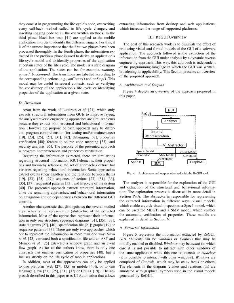
Figure 4 depicts an overview of the approach proposed inthis paper.
Fig. 4. Architecture and outputs obtained with the ReGUI tool
The analyser is responsible for the exploration of the GUIand extraction of the structural and behavioural informa-tion. The exploration process is discussed in more detail inSection IV-A. The abstractor is responsible for representingthe extracted information in different ways: visual models,which enable a quick visual inspection; a Spec# model, whichcan be used for MBGT; and a SMV model, which enablesthe automatic verification of properties. These models areexplained in detail in Section V.
B. Extracted Information
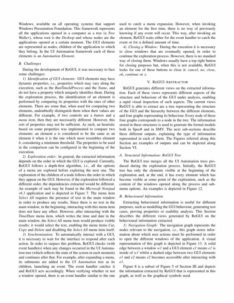
Figure 5 represents the information extracted by ReGUI.GUI Elements can be Windows or Controls that may beinitially enabled or disabled. Windows may be modal (in whichcase it is not possible to interact with other windows ofthe same application while this one is opened) or modeless(it is possible to interact with other windows). Windows arecomposed of Controls, which may be menu items or others.The elements in the diagram (classes and relationships) areannotated with graphical symbols used in the visual modelsgenerated by ReGUI.
class Logical View
Modal Window
Window
Modeless Window
GUI Element
name: String
...
Control
initiallyDisabled: Boolean
...
MenuItem OtherControl
Application
Filled symbol means initallyDisabled
Derived from "BelongsTo"
and "GivesAccessTo".
targetWindow *
/CanBeOpenedFrom
sourceWindow *
updateSource
*
UpdatesAPropertyOfupdateTarget
*
accessSource
*
GivesAccessToaccessTarget
*
*
BelongsTo
main
Window
1
Fig. 5. Annotated metamodel of the models generated by the ReGUI tool(see Figure 4)
The associations between the objects represent the extractedbehaviour. When interacting with a control, there are fivepossible identifiable outcomes:
• open - a window is opened;• close - a window is closed;• expansion - new controls become accessible. For instance,
the expansion of a menu;• update - one or more properties of one or more elements
are updated. For instance, the name of a window ismodified or an enabled control becomes disabled (or vice-versa);
• skip - nothing happens.
The first three outcomes are represented by the GivesAc-cessTo relation, while the third one is represented by theUpdatesAPropertyOf relation. If a control of a window (Be-longsTo relation) opens another window (GivesAccessTo rela-tion), then there is a CanBeOpenedFrom relation between thesecond and the first windows. This makes the last relation aderivation from the two previous ones.
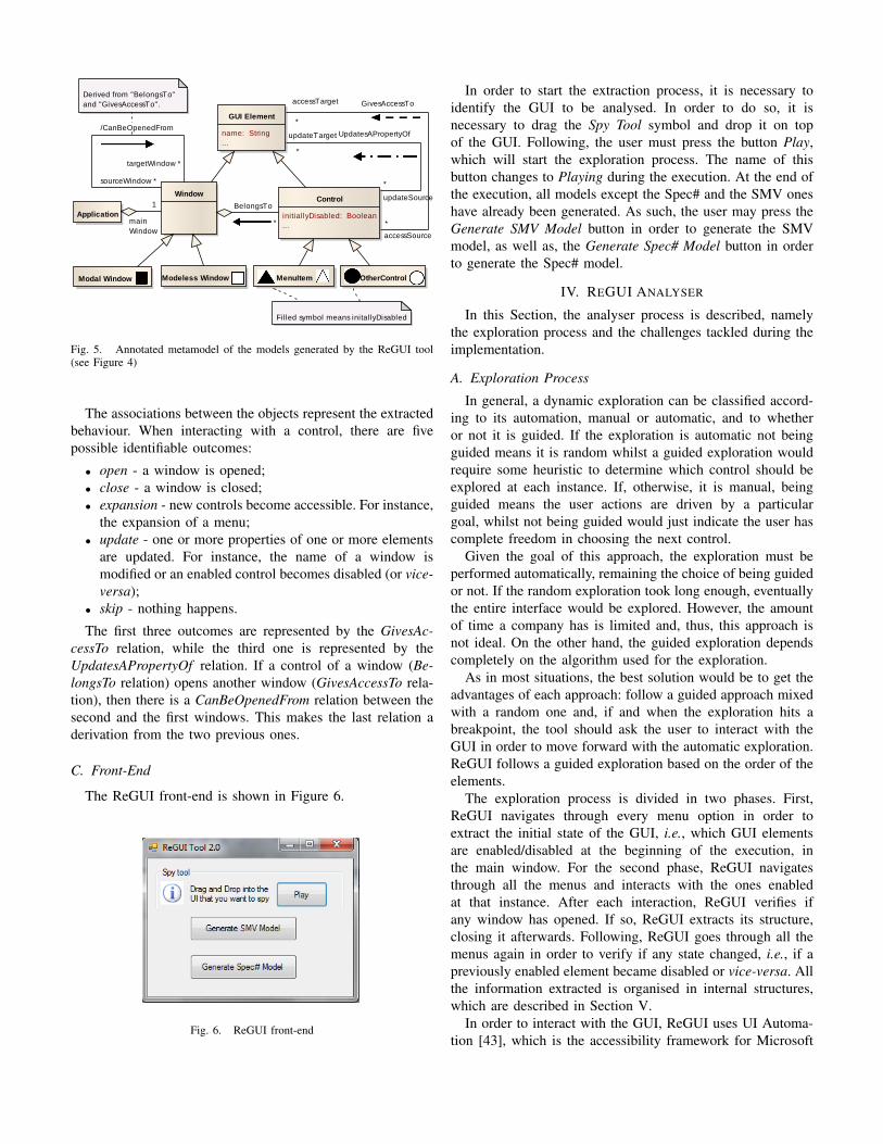
C. Front-End
The ReGUI front-end is shown in Figure 6.
Fig. 6. ReGUI front-end
In order to start the extraction process, it is necessary toidentify the GUI to be analysed. In order to do so, it isnecessary to drag the Spy Tool symbol and drop it on topof the GUI. Following, the user must press the button Play,which will start the exploration process. The name of thisbutton changes to Playing during the execution. At the end ofthe execution, all models except the Spec# and the SMV oneshave already been generated. As such, the user may press theGenerate SMV Model button in order to generate the SMVmodel, as well as, the Generate Spec# Model button in orderto generate the Spec# model.
IV. REGUI ANALYSER
In this Section, the analyser process is described, namelythe exploration process and the challenges tackled during theimplementation.
A. Exploration Process
In general, a dynamic exploration can be classified accord-ing to its automation, manual or automatic, and to whetheror not it is guided. If the exploration is automatic not beingguided means it is random whilst a guided exploration wouldrequire some heuristic to determine which control should beexplored at each instance. If, otherwise, it is manual, beingguided means the user actions are driven by a particulargoal, whilst not being guided would just indicate the user hascomplete freedom in choosing the next control.
Given the goal of this approach, the exploration must beperformed automatically, remaining the choice of being guidedor not. If the random exploration took long enough, eventuallythe entire interface would be explored. However, the amountof time a company has is limited and, thus, this approach isnot ideal. On the other hand, the guided exploration dependscompletely on the algorithm used for the exploration.
As in most situations, the best solution would be to get theadvantages of each approach: follow a guided approach mixedwith a random one and, if and when the exploration hits abreakpoint, the tool should ask the user to interact with theGUI in order to move forward with the automatic exploration.ReGUI follows a guided exploration based on the order of theelements.
The exploration process is divided in two phases. First,ReGUI navigates through every menu option in order toextract the initial state of the GUI, i.e., which GUI elementsare enabled/disabled at the beginning of the execution, inthe main window. For the second phase, ReGUI navigatesthrough all the menus and interacts with the ones enabledat that instance. After each interaction, ReGUI verifies ifany window has opened. If so, ReGUI extracts its structure,closing it afterwards. Following, ReGUI goes through all themenus again in order to verify if any state changed, i.e., if apreviously enabled element became disabled or vice-versa. Allthe information extracted is organised in internal structures,which are described in Section V.
In order to interact with the GUI, ReGUI uses UI Automa-tion [43], which is the accessibility framework for Microsoft
Windows, available on all operating systems that supportWindows Presentation Foundation. This framework representsall the applications opened in a computer as a tree (a TreeWalker), whose root is the Desktop and whose nodes are theapplications opened at a certain moment. The GUI elementsare represented as nodes, children of the application to whichthey belong. In the UI Automation framework each of theseelements is an Automation Element.
B. Challenges
During the development of ReGUI, it was necessary to facesome challenges:
1) Identification of GUI elements: GUI elements may havedynamic properties, i.e., properties which may vary along theexecution, such as the RunTimeIdProcess and the Name, anddo not have a property which uniquely identifies them. Duringthe exploration process, the identification of an element isperformed by comparing its properties with the ones of otherelements. There are some that, when used for comparing twoelements, undoubtedly distinguish them when their values aredifferent. For example, if two controls are a button and amenu item, then they are necessarily different. However, thissort of properties may not be sufficient. As such, an heuristicbased on some properties was implemented to compare twoelements: an element a is considered to be the same as anelement b when it is the one which most resembles elementb, considering a minimum threshold. The properties to be usedin the comparison can be configured in the beginning of theexecution.
2) Exploration order: In general, the extracted informationdepends on the order in which the GUI is explored. Currently,ReGUI follows a depth-first algorithm, i.e., all the optionsof a menu are explored before exploring the next one. Theexploration of the children of a node follows the order in whichthey appear on the GUI. However, if the exploration followed adifferent order, the dependencies extracted would be different.An example of such may be found in the Microsoft Notepadv6.1 application and is depicted in Figure 7. The menu itemSelect All requires the presence of text in the main windowin order to produce any results. Since there is no text in themain window, in the beginning, interacting with this menu itemdoes not have any effect. However, after interacting with theTime/Date menu item, which writes the time and date in themain window, the Select All menu item would produce visibleresults: it would select the text, enabling the menu items Cut,Copy and Delete and disabling the Select All menu item itself.
3) Synchronisation: To automatically interact with a GUI,it is necessary to wait for the interface to respond after eachaction. In order to surpass this problem, ReGUI checks (withevent handlers) when any changes occurred in the UI Automa-tion tree (which reflects the state of the screen in each moment)and continues after that. For example, after expanding a menu,its submenus are added to the UI Automation tree as itschildren, launching an event. The event handler catches itand ReGUI acts accordingly. When verifying whether or nota window opened, there is an event handler similar to the one
used to catch a menu expansion. However, when invokingan element for the first time, there is no way of previouslyknowing if any event will occur. This way, after invoking anelement, ReGUI waits either for the event handler to catch theevent or for a defined amount of time.
4) Closing a Window: During the execution it is necessaryto close windows that are eventually opened, in order tocontinue the exploration process. However, there is no standardway of closing them. Windows usually have a top right buttonfor closing purposes but, when this is not available, ReGUIlooks for one of these buttons to close it: cancel, no, close,ok, continue or x.
V. REGUI ABSTRACTOR
ReGUI generates different views on the extracted informa-tion. Each of these views represents different aspects of thestructure and behaviour of the GUI under analysis, enablinga rapid visual inspection of such aspects. The current viewsReGUI is able to extract are a tree representing the structureof the GUI and the hierarchy between the different elements,and four graphs representing its behaviour. Every node of thesefour graphs corresponds to a node in the tree. The informationstored in these structures is used to generate the formal modelsboth in Spec# and in SMV. The next sub-sections describethese different outputs, explaining the type of informationrepresented in each of them. The Figures referred along thisSection are examples of outputs and can be depicted alongSection VI.
A. Structural Information: ReGUI Tree
The ReGUI tree merges all the UI Automation trees pro-duced during the exploration process. Initially, the ReGUItree has only the elements visible at the beginning of theexploration and, at the end, it has every element which hasbecome visible at some point of the exploration, such as thecontent of the windows opened along the process and sub-menu options. An examples is depicted in Figure 12.
B. Behavioural Information
Extracting behavioural information is useful for differentpurposes, such as modelling the GUI behaviour, generating testcases, proving properties or usability analysis. This Sectiondescribes the different views generated by ReGUI on thebehavioural information extracted.
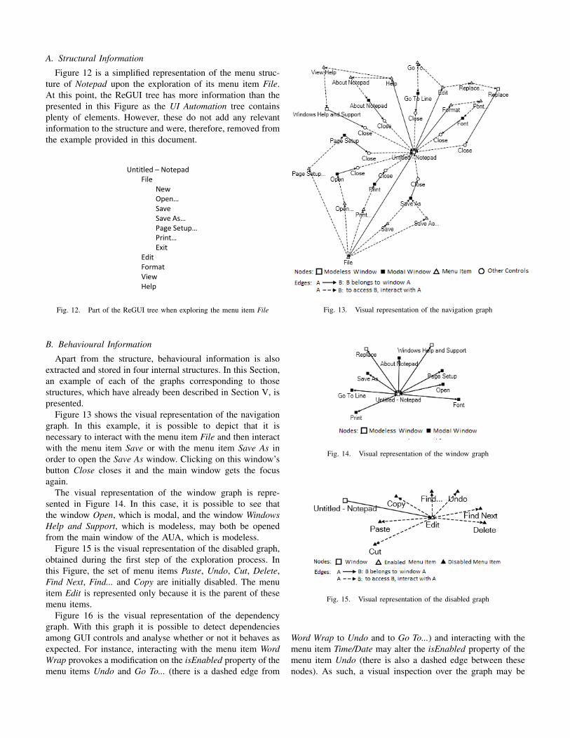
1) Navigation Graph: The navigation graph represents thenodes relevant to the navigation, i.e., this graph stores infor-mation about which user actions must be performed in orderto open the different windows of the application. A visualrepresentation of this graph is depicted in Figure 13. A solidedge between a window w1 and a GUI element e1 means e1 isinside of w1 whilst a dashed edge between two GUI elementse1 and e2 means e2 becomes accessible after interacting withe1.
Figure 8 is a subset of Figure 5 of Section III and depictsthe information extracted by ReGUI that is represented in thisgraph, as well as the graphical symbols used.

Fig. 7. Menu item Edit on Microsoft Notepad v6.1: a) after invoking the menu item Select All and before invoking the menu item Time/Date; b) afterinvoking the menu item Time/Date; c) after invoking again the menu item Select All
Fig. 8. Representation of the different elements and their relationships inthe navigation graph
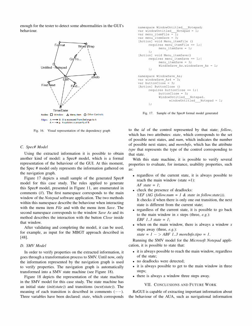
2) Window Graph: The window graph shows a subsetof the information represented by the navigation graph. Itdescribes the windows that may be opened in the application.Figure 14 is a visual representation of this graph. A windowmay be modal or modeless. An edge between two nodes w1and w2 means that it is possible to open window w2 byinteracting with elements of window w1.
Figure 9 is a subset of Figure 5 of Section III and depictsthe information extracted by ReGUI that is represented in thisgraph.
3) Disabled Graph: The disabled graph’s purpose is toshow which nodes are accessible but disabled int he begin-ning of the execution (obtained during the first phase of theexploration process described in Section IV-A). The enabledproperty of an element may vary during the second phase butthat modification is not represented in this graph. An exampleof this graph is depicted in Figure 15. The nodes correspondto some GUI elements, being filled when disabled and emptywhen enabled. A solid edge between two nodes n1 and n2means that n2 belongs to n1. On the other hand, a dashed edge
Fig. 9. Representation of the different elements and their relationships inthe window graph
between those nodes means n2 is accessible after interactingwith n1.
Figure 8 is also applicable to this graph as the relationsbetween the controls have the same meaning, even though theinformation represented in both graphs is different.
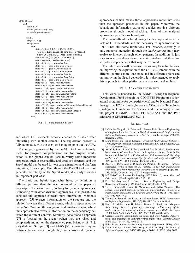
4) Dependency Graph: A dependency between two ele-ments A and B means that interacting with A modifies thevalue of a property of B. An example of a dependency wouldbe if interacting with A enabled a previously disabled B. Figure16 is the visual representation of a dependency graph obtainedduring an exploration process. A solid edge between a windoww1 and a node n1 means n1 is accessed from w1 and adashed edge between two nodes n1 and n2 means there isa dependency between n1 and n2.
Figure 10 is a subset of Figure 5 of Section III and depictsthe information extracted by ReGUI that is represented in thisgraph.
C. Spec# Model
Spec# is a formal specification language that can be usedas input to the model-based testing tool Spec Explorer [44],for automatic test generation.
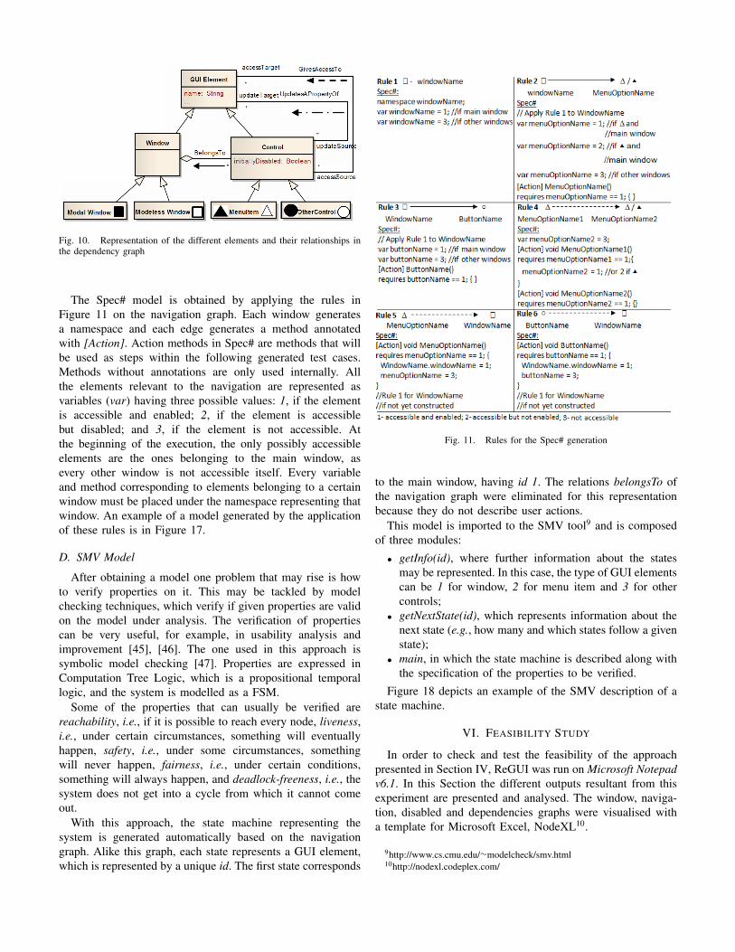
Fig. 10. Representation of the different elements and their relationships inthe dependency graph
The Spec# model is obtained by applying the rules inFigure 11 on the navigation graph. Each window generatesa namespace and each edge generates a method annotatedwith [Action]. Action methods in Spec# are methods that willbe used as steps within the following generated test cases.Methods without annotations are only used internally. Allthe elements relevant to the navigation are represented asvariables (var) having three possible values: 1, if the elementis accessible and enabled; 2, if the element is accessiblebut disabled; and 3, if the element is not accessible. Atthe beginning of the execution, the only possibly accessibleelements are the ones belonging to the main window, asevery other window is not accessible itself. Every variableand method corresponding to elements belonging to a certainwindow must be placed under the namespace representing thatwindow. An example of a model generated by the applicationof these rules is in Figure 17.
D. SMV Model
After obtaining a model one problem that may rise is howto verify properties on it. This may be tackled by modelchecking techniques, which verify if given properties are validon the model under analysis. The verification of propertiescan be very useful, for example, in usability analysis andimprovement [45], [46]. The one used in this approach issymbolic model checking [47]. Properties are expressed inComputation Tree Logic, which is a propositional temporallogic, and the system is modelled as a FSM.
Some of the properties that can usually be verified arereachability, i.e., if it is possible to reach every node, liveness,i.e., under certain circumstances, something will eventuallyhappen, safety, i.e., under some circumstances, somethingwill never happen, fairness, i.e., under certain conditions,something will always happen, and deadlock-freeness, i.e., thesystem does not get into a cycle from which it cannot comeout.
With this approach, the state machine representing thesystem is generated automatically based on the navigationgraph. Alike this graph, each state represents a GUI element,which is represented by a unique id. The first state corresponds
Fig. 11. Rules for the Spec# generation
to the main window, having id 1. The relations belongsTo ofthe navigation graph were eliminated for this representationbecause they do not describe user actions.
This model is imported to the SMV tool9 and is composedof three modules:
• getInfo(id), where further information about the statesmay be represented. In this case, the type of GUI elementscan be 1 for window, 2 for menu item and 3 for othercontrols;
• getNextState(id), which represents information about thenext state (e.g., how many and which states follow a givenstate);
• main, in which the state machine is described along withthe specification of the properties to be verified.
Figure 18 depicts an example of the SMV description of astate machine.
VI. FEASIBILITY STUDY
In order to check and test the feasibility of the approachpresented in Section IV, ReGUI was run on Microsoft Notepadv6.1. In this Section the different outputs resultant from thisexperiment are presented and analysed. The window, naviga-tion, disabled and dependencies graphs were visualised witha template for Microsoft Excel, NodeXL10.
9http://www.cs.cmu.edu/∼modelcheck/smv.html10http://nodexl.codeplex.com/
A. Structural Information
Figure 12 is a simplified representation of the menu struc-ture of Notepad upon the exploration of its menu item File.At this point, the ReGUI tree has more information than thepresented in this Figure as the UI Automation tree containsplenty of elements. However, these do not add any relevantinformation to the structure and were, therefore, removed fromthe example provided in this document.
Untitled – Notepad File New Open… Save Save As… Page Setup… Print… Exit Edit Format View Help
Fig. 12. Part of the ReGUI tree when exploring the menu item File
B. Behavioural Information
Apart from the structure, behavioural information is alsoextracted and stored in four internal structures. In this Section,an example of each of the graphs corresponding to thosestructures, which have already been described in Section V, ispresented.
Figure 13 shows the visual representation of the navigationgraph. In this example, it is possible to depict that it isnecessary to interact with the menu item File and then interactwith the menu item Save or with the menu item Save As inorder to open the Save As window. Clicking on this window’sbutton Close closes it and the main window gets the focusagain.
The visual representation of the window graph is repre-sented in Figure 14. In this case, it is possible to see thatthe window Open, which is modal, and the window WindowsHelp and Support, which is modeless, may both be openedfrom the main window of the AUA, which is modeless.
Figure 15 is the visual representation of the disabled graph,obtained during the first step of the exploration process. Inthis Figure, the set of menu items Paste, Undo, Cut, Delete,Find Next, Find... and Copy are initially disabled. The menuitem Edit is represented only because it is the parent of thesemenu items.
Figure 16 is the visual representation of the dependencygraph. With this graph it is possible to detect dependenciesamong GUI controls and analyse whether or not it behaves asexpected. For instance, interacting with the menu item WordWrap provokes a modification on the isEnabled property of themenu items Undo and Go To... (there is a dashed edge from
Fig. 13. Visual representation of the navigation graph
Fig. 14. Visual representation of the window graph
Fig. 15. Visual representation of the disabled graph
Word Wrap to Undo and to Go To...) and interacting with themenu item Time/Date may alter the isEnabled property of themenu item Undo (there is also a dashed edge between thesenodes). As such, a visual inspection over the graph may be
enough for the tester to detect some abnormalities in the GUI’sbehaviour.
Fig. 16. Visual representation of the dependency graph
C. Spec# Model
Using the extracted information it is possible to obtainanother kind of model: a Spec# model, which is a formalrepresentation of the behaviour of the GUI. At this moment,the Spec # model only represents the information gathered onthe navigation graph.
Figure 17 depicts a small sample of the generated Spec#model for this case study. The rules applied to generatethis Spec# model, presented in Figure 11, are enumerated incomments (//). The first namespace corresponds to the mainwindow of the Notepad software application. The two methodswithin this namespace describe the behaviour when interactingwith the menu item File and with the menu item Save. Thesecond namespace corresponds to the window Save As and itsmethod describes the interaction with the button Close insidethat window.
After validating and completing the model, it can be used,for example, as input for the MBGT approach described in[48].
D. SMV Model
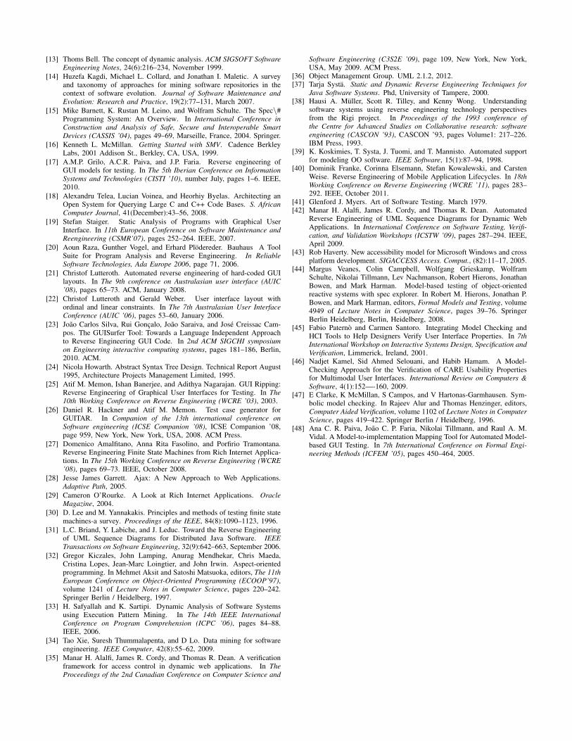
In order to verify properties on the extracted information, itgoes through a transformation process to SMV. Until now, onlythe information represented by the navigation graph is usedto verify properties. The navigation graph is automaticallytransformed into a SMV state machine (see Figure 18).
Figure 18 depicts the representation of the state machinein the SMV model for this case study. The state machine hasan initial state (init(state)) and transitions (next(state)). Themeaning of each transition is described in comments (−−).Three variables have been declared: state, which corresponds
namespace WindowUntitled___Notepad;
var windowUntitled___Notepad = 1;
var menu_itemFile = 1;
var menu_itemSave = 3;
[Action] void Menu_itemFile ()
requires menu_itemFile == 1;{
menu_itemSave = 1;
};
[Action] void Menu_itemSave()
requires menu_itemSave == 1;{
menu_itemSave = 3;
WindowSave_As.windowSave_As = 1;
};
namespace WindowSave_As;
var windowSave_As4 = 3;
var buttonClose = 3;
[Action] ButtonClose ()
requires buttonClose == 1;{
buttonClose = 3;
WindowUntitled___Notepad.
windowUntitled___Notepad = 1;
};
Fig. 17. Sample of the Spec# formal model generated
to the id of the control represented by that state; follow,which has two attributes: state, which corresponds to the setof possible next states, and num, which indicates the numberof possible next states; and moreInfo, which has the attributetype that represents the type of the control corresponding tothat state.
With this state machine, it is possible to verify severalproperties to evaluate, for instance, usability properties, suchas:
• regardless of the current state, it is always possible toreach the main window (state =1):AF state = 1;
• check the presence of deadlocks:!(EF (AG (follow.num = 1 & state in follow.state))).It checks if when there is only one out transition, the nextstate is different from the current state;
• regardless of the current state, it is possible to go backto the main window in x steps (three, e.g.):EBF 1..3 state = 1;
• when on the main window, there is always a window xsteps away (three, e.g.):state = 1 − > ABF 1..3 moreInfo.tipo = 1.
Running the SMV model for the Microsoft Notepad appli-cation, it is possible to state that:
• it is always possible to reach the main window, regardlessof the state;
• no deadlocks were detected;• it is always possible to get to the main window in three
steps;• there is always a window three steps away.
VII. CONCLUSIONS AND FUTURE WORK
ReGUI is capable of extracting important information aboutthe behaviour of the AUA, such as navigational information
MODULE main VAR state: 1..20; follow: getNextState(state); moreInfo: getInfo(state); ASSIGN init(state) := 1; next(state):= case state = 1: {2, 4, 6, 7, 9, 11, 13, 15, 17, 19}; --from state 1, it is possible to go to states 2 (Open...), --4 (Save), 6 (Save As...), 7 (Page Setup), 9 (Print…), --11 (Replace...), 13 (Go To...), 15 (Font...), --17 (View Help), 19 (About Notepad) state = 2: 3; --goes to window Open state = 3: 1; --goes to the main window state = 4: 5; --goes to window Save As state = 5: 1; --goes to the main window state = 6: 5; --goes to window Save As state = 7: 8; --goes to window Page Setup state = 8: 1; --goes to the main window state = 9: 10; --goes to window Print state = 10: 1; --goes to the main window state = 11: 12; --goes to window Replace state = 12: 1; --goes to the main window state = 13: 14; --goes to window Go To Line state = 14: 1; --goes to the main window state = 15: 16; --goes to window Font state = 16: 1; --goes to the main window state = 17: 18; --goes to window Windows Help and Support state = 18: 1; --goes to the main window state = 19: 20; --goes to window About Notepad state = 20: 1; --goes to the main window esac;
Fig. 18. State machine in SMV
and which GUI elements become enabled or disabled afterinteracting with another element. The exploration process isfully automatic, with the user just having to point out the AUA.
The outputs generated by the ReGUI tool are extremelyuseful for program comprehension and for program verifi-cation as the graphs can be used to verify some importantproperties, such as reachability and deadlock-freeness, and theSpec# model can be used for test case generation and platformmigration, for example. Even though the ReGUI tool does notgenerate the totality of the Spec# model, it already providesan important part of it.
The static and hybrid approaches have, by definition, adifferent purpose than the one presented in this paper asthey require the source code, contrary to dynamic approaches.Comparing with other dynamic approaches, it is possible toconclude this approach extracts more information. Memon’sapproach [25] extracts information on the structure and therelation between the different events, which is represented bythe ReGUI Tree and the navigation and window graphs, whilstthis approach also extracts information on the dependency be-tween the different controls. Similarly, Amalfitano’s approach[27] is focused on the events (when they are raised andcompleted) and not on the dependency part. Briand et al. [31],Safyallah and Sartipi [33] and Alafi’s [35] approaches requireinstrumentation, even though they are considered dynamic
approaches, which makes these approaches more intrusivesthan the approach presented in this paper. Moreover, thebehavioural information extracted enables proving differentproperties through model checking. None of the analysedapproaches provides such analysis.
The main difficulties faced during the development were thelack of GUI standards and the necessity of synchronisation.ReGUI has still some limitations. For instance, currently, itonly supports interaction through the invoke pattern but it mayevolve to interact through other patterns. In addition, it justtries to open windows from the main window and there arestill other dependencies that may be explored.
The future work will be focused on solving these limitations,on improving the exploration of the GUI, i.e., interact with thedifferent controls more than once and in different orders andon improving the Spec# generation. It is also intended to applythis approach to other platforms, such as web and mobile.
VIII. ACKNOWLEDGEMENTS
This work is financed by the ERDF - European RegionalDevelopment Fund through the COMPETE Programme (oper-ational programme for competitiveness) and by National Fundsthrough the FCT - Fundacao para a Ciencia e a Tecnologia(Portuguese Foundation for Science and Technology) withinthe project FCOMP-01-0124-FEDER-020554 and the PhDscholarship SFRH/BD/81075/2011.
REFERENCES
[1] I. Coimbra Morgado, A. Paiva, and J. Pascoal Faria. Reverse Engineeringof Graphical User Interfaces. In The Sixth International Conference onSoftware Engineering Advances (ICSEA ’11), number c, pages 293–298,Barcelona, 2011.
[2] Mark Utting and Bruno Legeard. Practical Model-Based Testing: ATools Approach. Morgan Kaufmann Publishers Inc., San Francisco, CA,USA, November 2007.
[3] Ana C. R. Paiva, Joao C. P. Faria, and Raul F. A. M. Vidal. Specification-based testing of user interfaces. In Joaquim A. Jorge, Nuno JardimNunes, and Joao Falcao e Cunha, editors, 10th International Workshopon Interactive Systems. Design, Specification, and Verification (DSV-IS’03), pages 139—-153, Funchal, Portugal, 2003.
[4] Ana C. R. Paiva, Joao C. P. Faria, and Pedro M. C. Mendes. Reverseengineered formal models for GUI testing. In The 12th internationalconference on Formal methods for industrial critical systems, pages 218–233, Berlin, Germany, July 2007. Springer-Verlag.
[5] MG Rekoff. On Reverse Engineering. IEEE Trans. Systems, Man, andCybernetics, (March-April):244 – 252, 1985.
[6] E.J. Chikofsky and J.H. Cross. Reverse Engineering and DesignRecovery: a Taxonomy. IEEE Software, 7(1):13–17, 1990.
[7] Ted J. Biggerstaff, Bharat G. Mitbander, and Dallas Webster. Theconcept assignment problem in program understanding. In The 15thinternational conference on Software Engineering (ICSE ’93), pages482–498, May 1993.
[8] Thomas A. Standish. An Essay on Software Reuse. IEEE Transactionson Software Engineering, SE-10(5):494–497, September 1984.
[9] Hausi A. Muller, Jens H. Jahnke, Dennis B. Smith, and Margaret-Anne Storey. Reverse engineering: a roadmap. In Proceedings of theconference on The future of Software engineering - ICSE ’00, pages47–60, New York, New York, USA, May 2000. ACM Press.
[10] Gerardo Canfora, Massimiliano Di Penta, and Luigi Cerulo. Achieve-ments and challenges in software reverse engineering. Communicationsof the ACM, 54(4):142, April 2011.
[11] Eldad Eilam. Reversing: Secrets of Reverse Engineering. Wiley, 2005.[12] David Binkley. Source Code Analysis: A Road Map. In Future of
Software Engineering (FOSE ’07), pages 104–119. IEEE, May 2007.
[13] Thoms Bell. The concept of dynamic analysis. ACM SIGSOFT SoftwareEngineering Notes, 24(6):216–234, November 1999.
[14] Huzefa Kagdi, Michael L. Collard, and Jonathan I. Maletic. A surveyand taxonomy of approaches for mining software repositories in thecontext of software evolution. Journal of Software Maintenance andEvolution: Research and Practice, 19(2):77–131, March 2007.
[15] Mike Barnett, K. Rustan M. Leino, and Wolfram Schulte. The Spec\#Programming System: An Overview. In International Conference inConstruction and Analysis of Safe, Secure and Interoperable SmartDevices (CASSIS ’04), pages 49–69, Marseille, France, 2004. Springer.
[16] Kenneth L. McMillan. Getting Started with SMV. Cadence BerkleyLabs, 2001 Addison St., Berkley, CA, USA, 1999.
[17] A.M.P. Grilo, A.C.R. Paiva, and J.P. Faria. Reverse engineering ofGUI models for testing. In The 5th Iberian Conference on InformationSystems and Technologies (CISTI ’10), number July, pages 1–6. IEEE,2010.
[18] Alexandru Telea, Lucian Voinea, and Heorhiy Byelas. Architecting anOpen System for Querying Large C and C++ Code Bases. S. AfricanComputer Journal, 41(December):43–56, 2008.
[19] Stefan Staiger. Static Analysis of Programs with Graphical UserInterface. In 11th European Conference on Software Maintenance andReengineering (CSMR’07), pages 252–264. IEEE, 2007.
[20] Aoun Raza, Gunther Vogel, and Erhard Plodereder. Bauhaus A ToolSuite for Program Analysis and Reverse Engineering. In ReliableSoftware Technologies, Ada Europe 2006, page 71, 2006.
[21] Christof Lutteroth. Automated reverse engineering of hard-coded GUIlayouts. In The 9th conference on Australasian user interface (AUIC’08), pages 65–73. ACM, January 2008.
[22] Christof Lutteroth and Gerald Weber. User interface layout withordinal and linear constraints. In The 7th Australasian User InterfaceConference (AUIC ’06), pages 53–60, January 2006.
[23] Joao Carlos Silva, Rui Goncalo, Joao Saraiva, and Jose Creissac Cam-pos. The GUISurfer Tool: Towards a Language Independent Approachto Reverse Engineering GUI Code. In 2nd ACM SIGCHI symposiumon Engineering interactive computing systems, pages 181–186, Berlin,2010. ACM.
[24] Nicola Howarth. Abstract Syntax Tree Design. Technical Report August1995, Architecture Projects Management Limited, 1995.
[25] Atif M. Memon, Ishan Banerjee, and Adithya Nagarajan. GUI Ripping:Reverse Engineering of Graphical User Interfaces for Testing. In The10th Working Conference on Reverse Engineering (WCRE ’03), 2003.
[26] Daniel R. Hackner and Atif M. Memon. Test case generator forGUITAR. In Companion of the 13th international conference onSoftware engineering (ICSE Companion ’08), ICSE Companion ’08,page 959, New York, New York, USA, 2008. ACM Press.
[27] Domenico Amalfitano, Anna Rita Fasolino, and Porfirio Tramontana.Reverse Engineering Finite State Machines from Rich Internet Applica-tions. In The 15th Working Conference on Reverse Engineering (WCRE’08), pages 69–73. IEEE, October 2008.
[28] Jesse James Garrett. Ajax: A New Approach to Web Applications.Adaptive Path, 2005.
[29] Cameron O’Rourke. A Look at Rich Internet Applications. OracleMagazine, 2004.
[30] D. Lee and M. Yannakakis. Principles and methods of testing finite statemachines-a survey. Proceedings of the IEEE, 84(8):1090–1123, 1996.
[31] L.C. Briand, Y. Labiche, and J. Leduc. Toward the Reverse Engineeringof UML Sequence Diagrams for Distributed Java Software. IEEETransactions on Software Engineering, 32(9):642–663, September 2006.
[32] Gregor Kiczales, John Lamping, Anurag Mendhekar, Chris Maeda,Cristina Lopes, Jean-Marc Loingtier, and John Irwin. Aspect-orientedprogramming. In Mehmet Aksit and Satoshi Matsuoka, editors, The 11thEuropean Conference on Object-Oriented Programming (ECOOP’97),volume 1241 of Lecture Notes in Computer Science, pages 220–242.Springer Berlin / Heidelberg, 1997.
[33] H. Safyallah and K. Sartipi. Dynamic Analysis of Software Systemsusing Execution Pattern Mining. In The 14th IEEE InternationalConference on Program Comprehension (ICPC ’06), pages 84–88.IEEE, 2006.
[34] Tao Xie, Suresh Thummalapenta, and D Lo. Data mining for softwareengineering. IEEE Computer, 42(8):55–62, 2009.
[35] Manar H. Alalfi, James R. Cordy, and Thomas R. Dean. A verificationframework for access control in dynamic web applications. In TheProceedings of the 2nd Canadian Conference on Computer Science and
Software Engineering (C3S2E ’09), page 109, New York, New York,USA, May 2009. ACM Press.
[36] Object Management Group. UML 2.1.2, 2012.[37] Tarja Systa. Static and Dynamic Reverse Engineering Techniques for
Java Software Systems. Phd, University of Tampere, 2000.[38] Hausi A. Muller, Scott R. Tilley, and Kenny Wong. Understanding
software systems using reverse engineering technology perspectivesfrom the Rigi project. In Proceedings of the 1993 conference ofthe Centre for Advanced Studies on Collaborative research: softwareengineering (CASCON ’93), CASCON ’93, pages Volume1: 217–226.IBM Press, 1993.
[39] K. Koskimies, T. Systa, J. Tuomi, and T. Mannisto. Automated supportfor modeling OO software. IEEE Software, 15(1):87–94, 1998.
[40] Dominik Franke, Corinna Elsemann, Stefan Kowalewski, and CarstenWeise. Reverse Engineering of Mobile Application Lifecycles. In 18thWorking Conference on Reverse Engineering (WCRE ’11), pages 283–292. IEEE, October 2011.
[41] Glenford J. Myers. Art of Software Testing. March 1979.[42] Manar H. Alalfi, James R. Cordy, and Thomas R. Dean. Automated
Reverse Engineering of UML Sequence Diagrams for Dynamic WebApplications. In International Conference on Software Testing, Verifi-cation, and Validation Workshops (ICSTW ’09), pages 287–294. IEEE,April 2009.
[43] Rob Haverty. New accessibility model for Microsoft Windows and crossplatform development. SIGACCESS Access. Comput., (82):11–17, 2005.
[44] Margus Veanes, Colin Campbell, Wolfgang Grieskamp, WolframSchulte, Nikolai Tillmann, Lev Nachmanson, Robert Hierons, JonathanBowen, and Mark Harman. Model-based testing of object-orientedreactive systems with spec explorer. In Robert M. Hierons, Jonathan P.Bowen, and Mark Harman, editors, Formal Models and Testing, volume4949 of Lecture Notes in Computer Science, pages 39–76. SpringerBerlin Heidelberg, Berlin, Heidelberg, 2008.
[45] Fabio Paterno and Carmen Santoro. Integrating Model Checking andHCI Tools to Help Designers Verify User Interface Properties. In 7thInternational Workshop on Interactive Systems Design, Specification andVerification, Limmerick, Ireland, 2001.
[46] Nadjet Kamel, Sid Ahmed Selouani, and Habib Hamam. A Model-Checking Approach for the Verification of CARE Usability Propertiesfor Multimodal User Interfaces. International Review on Computers &Software, 4(1):152—-160, 2009.
[47] E Clarke, K McMillan, S Campos, and V Hartonas-Garmhausen. Sym-bolic model checking. In Rajeev Alur and Thomas Henzinger, editors,Computer Aided Verification, volume 1102 of Lecture Notes in ComputerScience, pages 419–422. Springer Berlin / Heidelberg, 1996.
[48] Ana C. R. Paiva, Joao C. P. Faria, Nikolai Tillmann, and Raul A. M.Vidal. A Model-to-implementation Mapping Tool for Automated Model-based GUI Testing. In 7th International Conference on Formal Engi-neering Methods (ICFEM ’05), pages 450–464, 2005.