Dynamic control of DHM for ergonomic assessments
13
HAL Id: hal-00972324 https://hal.archives-ouvertes.fr/hal-00972324 Submitted on 3 Apr 2014 HAL is a multi-disciplinary open access archive for the deposit and dissemination of sci- entific research documents, whether they are pub- lished or not. The documents may come from teaching and research institutions in France or abroad, or from public or private research centers. L’archive ouverte pluridisciplinaire HAL, est destinée au dépôt et à la diffusion de documents scientifiques de niveau recherche, publiés ou non, émanant des établissements d’enseignement et de recherche français ou étrangers, des laboratoires publics ou privés. Dynamic control of DHM for ergonomic assessments Giovanni de Magistris, Alain Micaelli, Paul Evrard, Claude Andriot, Jonathan Savin, Clarisse Gaudez, Jacques Marsot To cite this version: Giovanni de Magistris, Alain Micaelli, Paul Evrard, Claude Andriot, Jonathan Savin, et al.. Dynamic control of DHM for ergonomic assessments. International Journal of Industrial Ergonomics, Elsevier, 2013, 43, pp.170-180. 10.1016/j.ergon.2013.01.003. hal-00972324
Transcript of Dynamic control of DHM for ergonomic assessments
HAL Id: hal-00972324https://hal.archives-ouvertes.fr/hal-00972324
Submitted on 3 Apr 2014
HAL is a multi-disciplinary open accessarchive for the deposit and dissemination of sci-entific research documents, whether they are pub-lished or not. The documents may come fromteaching and research institutions in France orabroad, or from public or private research centers.
L’archive ouverte pluridisciplinaire HAL, estdestinée au dépôt et à la diffusion de documentsscientifiques de niveau recherche, publiés ou non,émanant des établissements d’enseignement et derecherche français ou étrangers, des laboratoirespublics ou privés.
Dynamic control of DHM for ergonomic assessmentsGiovanni de Magistris, Alain Micaelli, Paul Evrard, Claude Andriot, Jonathan
Savin, Clarisse Gaudez, Jacques Marsot
To cite this version:Giovanni de Magistris, Alain Micaelli, Paul Evrard, Claude Andriot, Jonathan Savin, et al.. Dynamiccontrol of DHM for ergonomic assessments. International Journal of Industrial Ergonomics, Elsevier,2013, 43, pp.170-180. �10.1016/j.ergon.2013.01.003�. �hal-00972324�
Dynamic control of DHM for ergonomic assessments
Giovanni De Magistrisa,∗, Alain Micaellia, Paul Evrarda, Claude Andriota, Jonathan Savinb, Clarisse Gaudezb, JacquesMarsotb
aCEA, LIST, Interactive Simulation Laboratory, 18 route du panorama, BP6, Fontenay aux Roses, F- 92265 FrancebInstitut national de recherche et de securite (INRS), rue du Morvan, CS 60027, Vandœuvre-les-Nancy, F- 54519 France
Abstract
Physical risk factors assessment is usually conducted by analysing postures and forces implemented by the operatorduring a work-task performance. A basic analysis can rely on questionnaires and video analysis, but more accuratecomprehensive analysis generally requires complex expensive instrumentation, which may hamper movement task per-formance.In recent years, it has become possible to study the ergonomic aspects of a workstation from the initial design pro-cess, by using digital human model (DHM) software packages such as Pro/ENGINEER Manikin, JACK, RAMSIS orCATIA-DELMIA Human. However, a number of limitations concerning the use of DHM have been identified, for ex-ample biomechanical approximations, static calculation, description of the probable future situation or statistical dataon human performance characteristics. Furthermore, the most common DHM used in the design process are controlledthrough inverse kinematic techniques, which may not be suitable for all situations to be simulated.A dynamic DHM automatically controlled in force and acceleration would therefore be an important contribution toanalysing ergonomic aspects, especially when it comes to movement, applied forces and joint torques evaluation. Such aDHM would fill the gap between measurements made on the operator performing the task and simulations made usinga static DHM.In this paper, we introduce the principles of a new autonomous dynamic DHM, then describe an application and valida-tion case based on an industrial assembly task adapted and implemented in the laboratory. An ergonomic assessment ofboth the real task and the simulation was conducted based on analysing the operator/manikin’s joint angles and appliedforce in accordance with machinery safety standards (Standard NF EN ISO 1005-1 to 5 and OCcupational RepetitiveActions (OCRA) index). Given minimum description parameters of the task and subject, our DHM provides a simulationwhose ergonomic assessment agrees with experimental evaluation.
Keywords: Digital Human Model, Dynamic control, Ergonomic analysis, Virtual reality
1. Introduction
Work-related musculoskeletal disorders (WRMSD) rep-resent a major proportion of registered and/or compensa-table work-related diseases in many countries, (Sjogaardet al., 1995)(Bernard, 1997), particularly those involvingthe lower back, neck, shoulder, forearm and wrist.
Several studies have identified a relationship between”work-related” diseases and physical risk factors at work(Bernard, 1997)(Kao, 2003). Job physical characteristicsfrequently quoted as WRMSD risk factors, based on exper-imental science and epidemiologic investigations, includerapid and repetitive motion patterns, heavy lifting, force-ful manual exertions or prolonged static postures. As a re-sult, safety standards have gradually detailed those issuesand physical risk factor assessment at the earliest designstages has become a concern for industrial companies.
∗Corresponding author. Tel: +33 01 46 54 74 50 Email address:[email protected] (G. De Magistris)
A basic analysis of a task can rely on questionnaires,interviews and video analysis. Besides, numerous indica-tors can be used for physical risk assessment of job activ-ities, usually specific to a body part or a type of activity:commonly encountered assessment methodologies includeRULA (MacAtamney and Cortlett, 1993) for the upperlimbs, REBA (Hignett and MacAtamney, 2000) for thewhole body, NIOSH equations, standards such as NF EN1005 - Part2 (AFNOR, 2003) for load handling or NF EN1005 - Part 5 (AFNOR, 2007) for repetitive tasks (thisstandard is based on the OCcupational Repetitive Action(OCRA) method (Occhipinti, 1998)). A more accurateand comprehensive analysis requires collection of exertion(force sensor and/or electromyography) and posture data(e.g. motion capture technique) from operators perform-ing similar tasks. This analysis entails complex expensiveinstrumentation that may hamper task performance.
When designing a new task, an alternative is to usedigital human models (DHM) for ergonomic analysis.For example, Sub-section 4.2.5 of EN 1005-4 states that
Preprint submitted to International Journal of Industrial Ergonomics March 3, 2014
DHM can be used for anthropometry and postures as-sessment (AFNOR, 2008). Using DHM, it is currentlypossible to study, analyze and visualize complex move-ments or postures in a user-friendly three-dimensionalgraphical interface. Hence, an initial level of futureworkstation ergonomic assessment is possible even atthe early stages of the design process without the needfor direct measurements on human subjects (Chaffin,2005)(Gomes et al., 1999)(Dukic et al., 2007). Examplesof DHM software packages used for ergonomic assessmentare Pro/ENGINEER Manikin Analysis, SAMMIE (Porteret al., 2004), JACK (Badler, 1997), CATIA-HUMAN De-sign and Analysis tools, RAMSIS and SANTOS.
However the simulations computed with these softwarepackages usually rely on kinematics animation frameworks.Such frameworks use either pre-recorded motions, ob-tained through tracking system and motion capture, orinteractive manual positioning of the DHM body throughmouse, menus and keyboard. In the first case, simulationsare realistic but they require extensive instrumentation ofa full scale mock-up of the future workstation or a similarexisting one. They are extremely time consuming becauseof motion capture data processing (Bradwell and Li, 2008).Furthermore, their ability to predict complex human pos-tures and movements for various sizes and dimensions ina timely and realistic manner is strictly dependent on theaccuracy of the motion database. In the second case, sim-ulations are fairly subjective (the designer, possibly withno specific ergonomic skill, chooses arbitrarily a postureor trajectory). Again, they are time consuming (builtup like a cartoon) or usually appear unnatural (Chaffin,2007), even though they possess semi-automatic controlsprovided by a set of behaviours such as gazing, reaching,walking and grasping. These issues do not encourage de-signers to consider alternative scenarios, which would bebeneficial for a comprehensive assessment of the futurework situation. Moreover, such software packages are sub-ject to numerous limitations: restriction to static modelsand calculation, neglect of balance or posture maintainingexertion. Neither do they consider contact forces betweenthe DHM and objects (at best the designer has to arbi-trarily set the contact force magnitude and direction man-ually). For these reasons, assessment of biomechanical riskfactors, based on simulations of industrial or experimentalsituations, may lead to real stress underestimation up to40-50% (Lamkull et al., 2009) (Savin, 2011).
A challenging aim therefore consists in developing a vir-tual human model capable of computing automatic, dy-namic, realistic movements and internal characteristics(position, velocities, accelerations and torques) in quasi-real time, based on a simple description of the future worktask, to achieve realistic ergonomics assessments of variouswork task scenarii at an early stage of the design process.
This type of dynamic DHM controlled in accelerationand force using simulated physics, forms the crux of ourresearch. In our simulation framework, the entire motionof the human model in the virtual environment is dictated
by real-world Newtonian physical and mechanical simula-tion, along with automatic control of applied forces andtorques. We focus on repetitive tasks of the upper limbin this paper, which introduces our virtual human modeland demonstrates its possibilities for physical risk evalua-tion at the design stage. The first and the second parts ofthe paper describe the application case used as an exper-imental and validation frame, then outline the principlesof our dynamic DHM controls. The third part describesits outcomes, especially comparison of assessments basedon real and simulated data. Finally, in the fourth part, wediscuss the issues raised by the approach and its prospects.
2. Human Subject Experiment
2.1. Experimental task description
The research frame focuses on repetitive activities thatpresent a significant risk of upper limb WRMSD. Our casestudy deals with the task of insert fitting. This activ-ity comes from the automotive industry but can also befound in electric household appliance or other industries,in which the constant product evolution results in frequent,quick changes to production lines, requiring multiple man-ual operations. Insert fitting here consists in clipping smallmetal parts to the plastic instrument panel of a vehicleprior to screwing components to the panel.
2.2. Subjects
Our application case was first studied during an er-gonomic assistance assignment conducted by France’s In-stitut national de recherche et de securite (INRS), Labo-ratory for Biomechanics and Ergonomics (Gaudez, 2008).The same team subsequently adapted it to laboratory ex-perimentation in accordance with biomedical research re-quirements. Eleven healthy right-handed subjects (ninemales and two females) took part in the study [age = 29.4± 9.2 yrs (mean ± standard deviation), height = 177.7 ±10.3 cm, body mass = 75.9 ± 9.3 kg]. The subjects gavetheir informed consent to the experiments, which were ap-proved by the institutional ethics committee, and com-pleted a health questionnaire. The subject’s anthropom-etry was measured to build human subject models basedon the Hanavan model (Hanavan, 1964) (size, weight and41 body segment measurements).
2.3. Apparatus
The workstation comprised a force platform assembledon a lift table fitted with a row of ten insert supportsarranged at 45° from back to front in the sagittal plane.
A ten camera Motion Analysis System was implementedto record the whole body positions and postures. A singletop view camera, synchronized with the motion capturesystem, was used to record the subject’s activity: theserecordings could subsequently be used to view the realmovements and correct for marker losses or hidden move-ments.
2
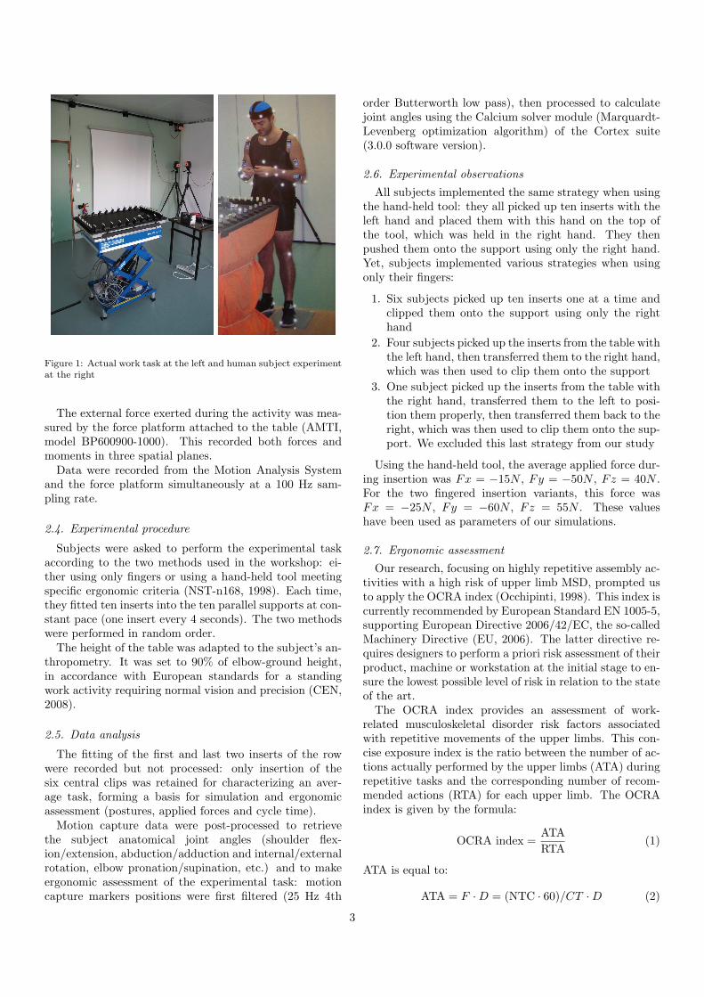
Figure 1: Actual work task at the left and human subject experimentat the right
The external force exerted during the activity was mea-sured by the force platform attached to the table (AMTI,model BP600900-1000). This recorded both forces andmoments in three spatial planes.
Data were recorded from the Motion Analysis Systemand the force platform simultaneously at a 100 Hz sam-pling rate.
2.4. Experimental procedure
Subjects were asked to perform the experimental taskaccording to the two methods used in the workshop: ei-ther using only fingers or using a hand-held tool meetingspecific ergonomic criteria (NST-n168, 1998). Each time,they fitted ten inserts into the ten parallel supports at con-stant pace (one insert every 4 seconds). The two methodswere performed in random order.
The height of the table was adapted to the subject’s an-thropometry. It was set to 90% of elbow-ground height,in accordance with European standards for a standingwork activity requiring normal vision and precision (CEN,2008).
2.5. Data analysis
The fitting of the first and last two inserts of the rowwere recorded but not processed: only insertion of thesix central clips was retained for characterizing an aver-age task, forming a basis for simulation and ergonomicassessment (postures, applied forces and cycle time).
Motion capture data were post-processed to retrievethe subject anatomical joint angles (shoulder flex-ion/extension, abduction/adduction and internal/externalrotation, elbow pronation/supination, etc.) and to makeergonomic assessment of the experimental task: motioncapture markers positions were first filtered (25 Hz 4th
order Butterworth low pass), then processed to calculatejoint angles using the Calcium solver module (Marquardt-Levenberg optimization algorithm) of the Cortex suite(3.0.0 software version).
2.6. Experimental observations
All subjects implemented the same strategy when usingthe hand-held tool: they all picked up ten inserts with theleft hand and placed them with this hand on the top ofthe tool, which was held in the right hand. They thenpushed them onto the support using only the right hand.Yet, subjects implemented various strategies when usingonly their fingers:
1. Six subjects picked up ten inserts one at a time andclipped them onto the support using only the righthand
2. Four subjects picked up the inserts from the table withthe left hand, then transferred them to the right hand,which was then used to clip them onto the support
3. One subject picked up the inserts from the table withthe right hand, transferred them to the left to posi-tion them properly, then transferred them back to theright, which was then used to clip them onto the sup-port. We excluded this last strategy from our study
Using the hand-held tool, the average applied force dur-ing insertion was Fx = −15N , Fy = −50N , Fz = 40N .For the two fingered insertion variants, this force wasFx = −25N , Fy = −60N , Fz = 55N . These valueshave been used as parameters of our simulations.
2.7. Ergonomic assessment
Our research, focusing on highly repetitive assembly ac-tivities with a high risk of upper limb MSD, prompted usto apply the OCRA index (Occhipinti, 1998). This index iscurrently recommended by European Standard EN 1005-5,supporting European Directive 2006/42/EC, the so-calledMachinery Directive (EU, 2006). The latter directive re-quires designers to perform a priori risk assessment of theirproduct, machine or workstation at the initial stage to en-sure the lowest possible level of risk in relation to the stateof the art.
The OCRA index provides an assessment of work-related musculoskeletal disorder risk factors associatedwith repetitive movements of the upper limbs. This con-cise exposure index is the ratio between the number of ac-tions actually performed by the upper limbs (ATA) duringrepetitive tasks and the corresponding number of recom-mended actions (RTA) for each upper limb. The OCRAindex is given by the formula:
OCRA index =ATA
RTA(1)
ATA is equal to:
ATA = F ·D = (NTC · 60)/CT ·D (2)
3
F is the frequency per minute, NTC is the number of tech-nical actions in a cycle, CT is the cycle time in seconds,and D is the evaluated net duration of the repetitive taskduring the work shift in minutes.RTA is equal to:
RTA = RPA · (RcM ·DuM )
= CF · PoM ·ReM ·AdM · FoM ·D · (RcM ·DuM )(3)
RPA is the partial reference number of technical actionfor task; CF is the frequency constant of technical actionsper minute, used as a reference (30 actions per minute);the other multiplying factors, with scores ranging between0 and 1, depend on posture (PoM ), repetitiveness (ReM ),additional (AdM ) risk factors (vibrating tools, exposure tocold or refrigeration, etc.), force (FoM ), recovery (RcM ),selected based on lack of recovery behavior and duration(DuM ).
Table 1 is used to assess the risk. Level 1 (no risk) in-dicates that the condition examined is fully acceptable,the level 2 (low risk) indicates that the exposure may besignificant and careful monitoring for induced health ef-fects should be introduced (health surveillance). Level 3(risk) indicates that the exposure is definitely significantand the higher the value, the higher the risk. In this case,actions should be undertaken to improve working condi-tions, along with close monitoring for induced effects.
Level OCRA Index Values Risk Level
1 < 2.2 No risk2 2.3-3.5 Low risk3 > 3.5 Risk
Table 1: Final Assessment Criteria (OCRA Method)
3. DHM simulation
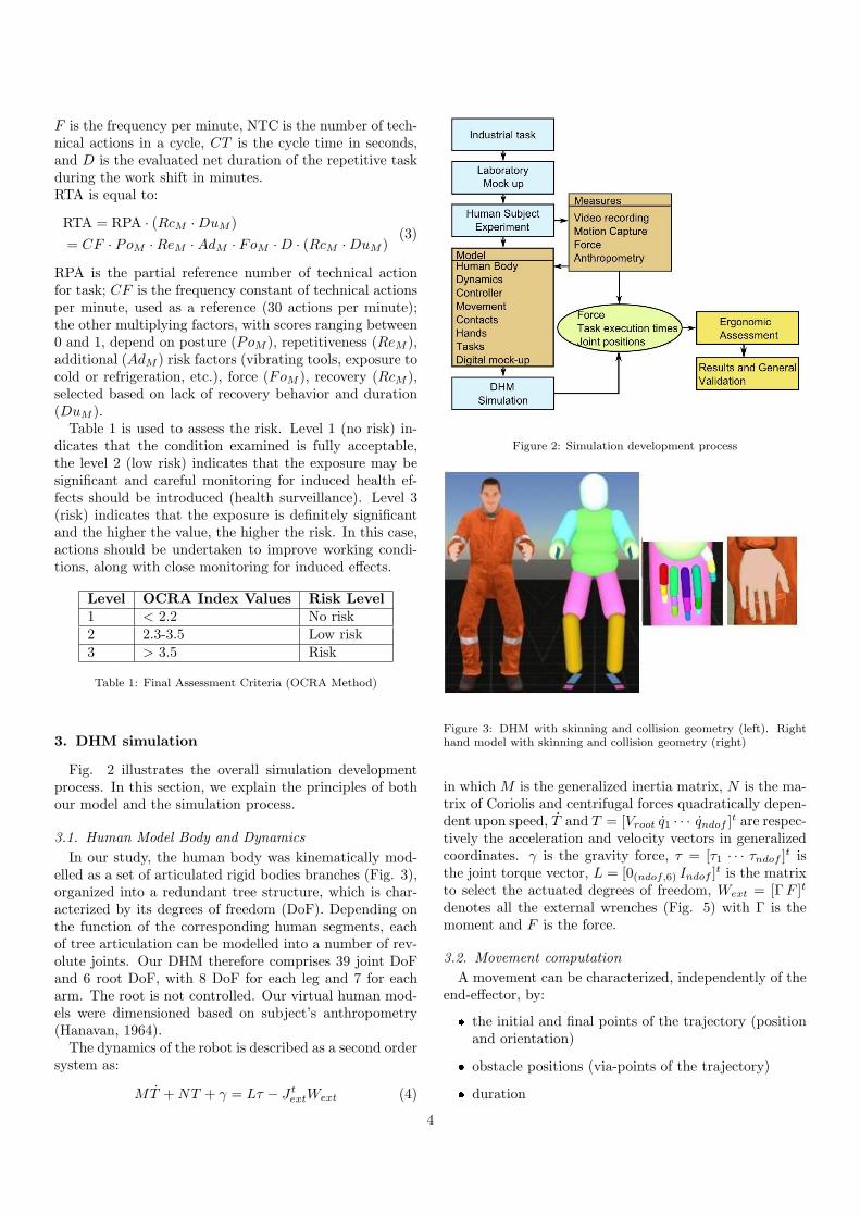
Fig. 2 illustrates the overall simulation developmentprocess. In this section, we explain the principles of bothour model and the simulation process.
3.1. Human Model Body and Dynamics
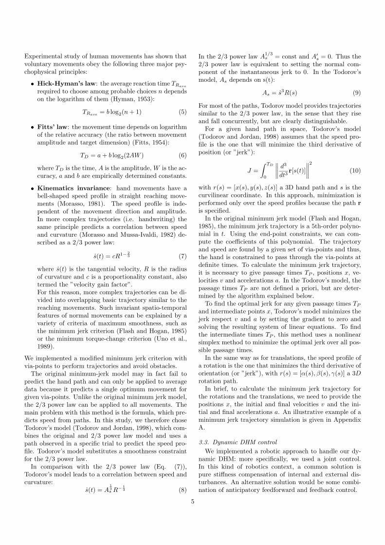
In our study, the human body was kinematically mod-elled as a set of articulated rigid bodies branches (Fig. 3),organized into a redundant tree structure, which is char-acterized by its degrees of freedom (DoF). Depending onthe function of the corresponding human segments, eachof tree articulation can be modelled into a number of rev-olute joints. Our DHM therefore comprises 39 joint DoFand 6 root DoF, with 8 DoF for each leg and 7 for eacharm. The root is not controlled. Our virtual human mod-els were dimensioned based on subject’s anthropometry(Hanavan, 1964).
The dynamics of the robot is described as a second ordersystem as:
MT +NT + γ = Lτ − J textWext (4)
Figure 2: Simulation development process
Figure 3: DHM with skinning and collision geometry (left). Righthand model with skinning and collision geometry (right)
in which M is the generalized inertia matrix, N is the ma-trix of Coriolis and centrifugal forces quadratically depen-dent upon speed, T and T = [Vroot q1 · · · qndof ]
t are respec-tively the acceleration and velocity vectors in generalizedcoordinates. γ is the gravity force, τ = [τ1 · · · τndof ]
t isthe joint torque vector, L = [0(ndof,6) Indof ]
t is the matrixto select the actuated degrees of freedom, Wext = [ΓF ]t
denotes all the external wrenches (Fig. 5) with Γ is themoment and F is the force.
3.2. Movement computation
A movement can be characterized, independently of theend-effector, by:
� the initial and final points of the trajectory (positionand orientation)
� obstacle positions (via-points of the trajectory)
� duration
4
Experimental study of human movements has shown thatvoluntary movements obey the following three major psy-chophysical principles:
� Hick-Hyman’s law: the average reaction time TRave
required to choose among probable choices n dependson the logarithm of them (Hyman, 1953):
TRave= b log2(n+ 1) (5)
� Fitts’ law: the movement time depends on logarithmof the relative accuracy (the ratio between movementamplitude and target dimension) (Fitts, 1954):
TD = a+ b log2(2AW ) (6)
where TD is the time, A is the amplitude, W is the ac-curacy, a and b are empirically determined constants.
� Kinematics invariance: hand movements have abell-shaped speed profile in straight reaching move-ments (Morasso, 1981). The speed profile is inde-pendent of the movement direction and amplitude.In more complex trajectories (i.e. handwriting) thesame principle predicts a correlation between speedand curvature (Morasso and Mussa-Ivaldi, 1982) de-scribed as a 2/3 power law:
s(t) = cR1− 2
3 (7)
where s(t) is the tangential velocity, R is the radiusof curvature and c is a proportionality constant, alsotermed the ”velocity gain factor”.For this reason, more complex trajectories can be di-vided into overlapping basic trajectory similar to thereaching movements. Such invariant spatio-temporalfeatures of normal movements can be explained by avariety of criteria of maximum smoothness, such asthe minimum jerk criterion (Flash and Hogan, 1985)or the minimum torque-change criterion (Uno et al.,1989).
We implemented a modified minimum jerk criterion withvia-points to perform trajectories and avoid obstacles.
The original minimum-jerk model may in fact fail topredict the hand path and can only be applied to averagedata because it predicts a single optimum movement forgiven via-points. Unlike the original minimum jerk model,the 2/3 power law can be applied to all movements. Themain problem with this method is the formula, which pre-dicts speed from paths. In this study, we therefore choseTodorov’s model (Todorov and Jordan, 1998), which com-bines the original and 2/3 power law model and uses apath observed in a specific trial to predict the speed pro-file. Todorov’s model substitutes a smoothness constraintfor the 2/3 power law.
In comparison with the 2/3 power law (Eq. (7)),Todorov’s model leads to a correlation between speed andcurvature:
s(t) = A1
3
s R−
1
3 (8)
In the 2/3 power law A1/3s = const and A′
s = 0. Thus the2/3 power law is equivalent to setting the normal com-ponent of the instantaneous jerk to 0. In the Todorov’smodel, As depends on s(t):
As = s3R(s) (9)
For most of the paths, Todorov model provides trajectoriessimilar to the 2/3 power law, in the sense that they riseand fall concurrently, but are clearly distinguishable.
For a given hand path in space, Todorov’s model(Todorov and Jordan, 1998) assumes that the speed pro-file is the one that will minimize the third derivative ofposition (or ”jerk”):
J =
∫ TD
0
∥
∥
∥
∥
d3
dt3r[s(t)]
∥
∥
∥
∥
2
(10)
with r(s) = [x(s), y(s), z(s)] a 3D hand path and s is thecurvilinear coordinate. In this approach, minimization isperformed only over the speed profiles because the path r
is specified.In the original minimum jerk model (Flash and Hogan,
1985), the minimum jerk trajectory is a 5th-order polyno-mial in t. Using the end-point constraints, we can com-pute the coefficients of this polynomial. The trajectoryand speed are found by a given set of via-points and thus,the hand is constrained to pass through the via-points atdefinite times. To calculate the minimum jerk trajectory,it is necessary to give passage times TP , positions x, ve-locities v and accelerations a. In the Todorov’s model, thepassage times TP are not defined a priori, but are deter-mined by the algorithm explained below.
To find the optimal jerk for any given passage times TP
and intermediate points x, Todorov’s model minimizes thejerk respect v and a by setting the gradient to zero andsolving the resulting system of linear equations. To findthe intermediate times TP , this method uses a nonlinearsimplex method to minimize the optimal jerk over all pos-sible passage times.
In the same way as for translations, the speed profile ofa rotation is the one that minimizes the third derivative oforientation (or ”jerk”), with r(s) = [α(s), β(s), γ(s)] a 3Drotation path.
In brief, to calculate the minimum jerk trajectory forthe rotations and the translations, we need to provide thepositions x, the initial and final velocities v and the ini-tial and final accelerations a. An illustrative example of aminimum jerk trajectory simulation is given in AppendixA.
3.3. Dynamic DHM control
We implemented a robotic approach to handle our dy-namic DHM: more specifically, we used a joint control.In this kind of robotics context, a common solution ispure stiffness compensation of internal and external dis-turbances. An alternative solution would be some combi-nation of anticipatory feedforward and feedback control.
5
This reasoning is especially suited to human simulation.A number of studies have shown that the central nervoussystem (CNS) uses internal representations to anticipatethe consequences of dynamic interaction forces. In par-ticular, (Lackner and Dizio, 1994) demonstrated that theCNS is able to predict the centripetal and Coriolis forces;(Gribble and Ostry, 1999) demonstrated the compensationof interaction torques during multijoint limb movement.These studies suggest that the nervous system has sophis-ticated anticipatory capabilities. This is why we need todesign accurate internal models of body dynamic and con-tact.
Generally, a feedforward control model is based on theanticipatory computation of the forces that will be neededby the system to carry out a desired motion plan, withoutsensory information. It corresponds to solving motion Eq.(4) with respect to the torques generated by the actuators.
An illustrative example is Kawato’s feedback error learn-ing model (Kawato and Gomi, 1992), based on cooper-ation between of two control mechanisms: a feedbackloop, which operates in an initial training phase, and thefeedforward model, which subsequently emerges. In thismodel, the feedback error is used as the learning signal forthe feedforward model, which gradually takes control anydynamic disturbances, and thereby acquires an internalmodel of the body dynamics.
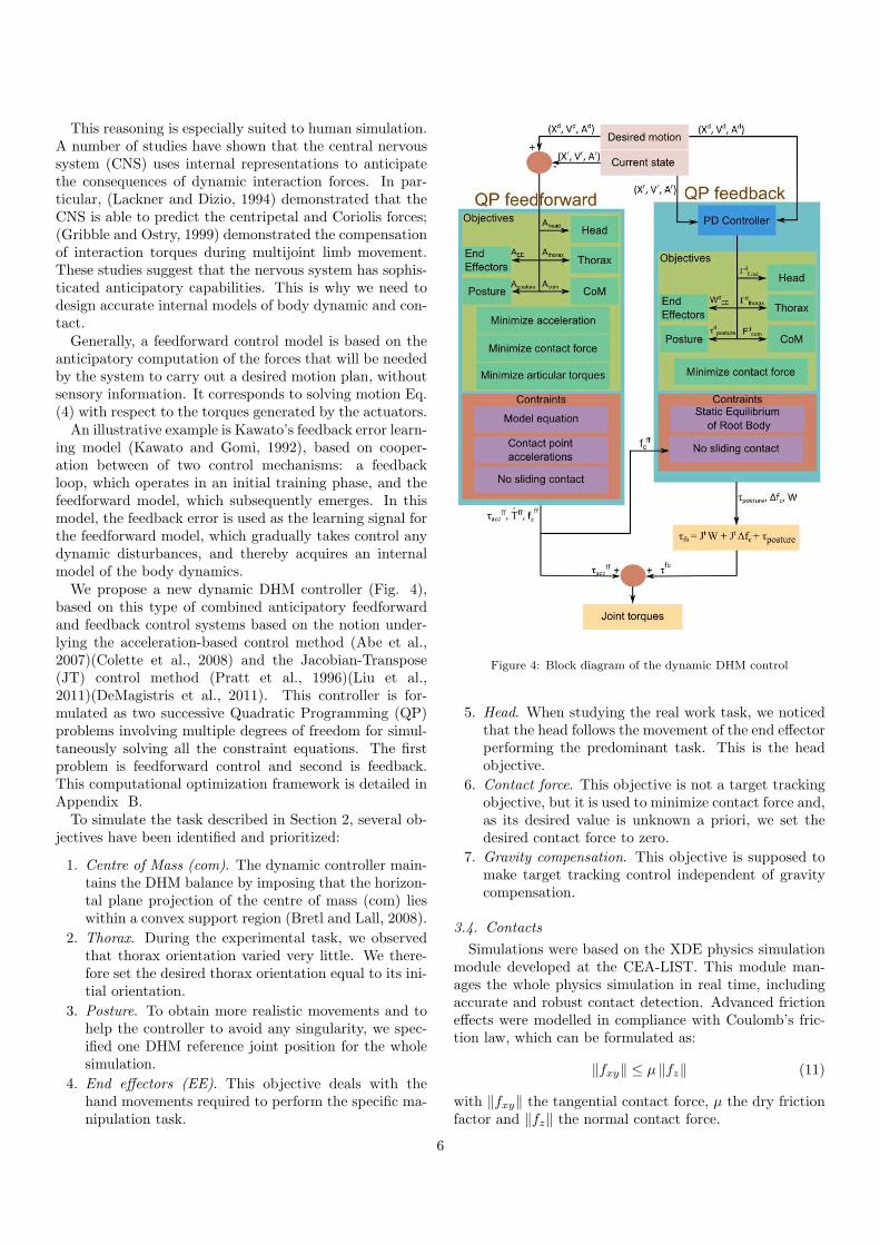
We propose a new dynamic DHM controller (Fig. 4),based on this type of combined anticipatory feedforwardand feedback control systems based on the notion under-lying the acceleration-based control method (Abe et al.,2007)(Colette et al., 2008) and the Jacobian-Transpose(JT) control method (Pratt et al., 1996)(Liu et al.,2011)(DeMagistris et al., 2011). This controller is for-mulated as two successive Quadratic Programming (QP)problems involving multiple degrees of freedom for simul-taneously solving all the constraint equations. The firstproblem is feedforward control and second is feedback.This computational optimization framework is detailed inAppendix B.
To simulate the task described in Section 2, several ob-jectives have been identified and prioritized:
1. Centre of Mass (com). The dynamic controller main-tains the DHM balance by imposing that the horizon-tal plane projection of the centre of mass (com) lieswithin a convex support region (Bretl and Lall, 2008).
2. Thorax. During the experimental task, we observedthat thorax orientation varied very little. We there-fore set the desired thorax orientation equal to its ini-tial orientation.
3. Posture. To obtain more realistic movements and tohelp the controller to avoid any singularity, we spec-ified one DHM reference joint position for the wholesimulation.
4. End effectors (EE). This objective deals with thehand movements required to perform the specific ma-nipulation task.
Figure 4: Block diagram of the dynamic DHM control
5. Head. When studying the real work task, we noticedthat the head follows the movement of the end effectorperforming the predominant task. This is the headobjective.
6. Contact force. This objective is not a target trackingobjective, but it is used to minimize contact force and,as its desired value is unknown a priori, we set thedesired contact force to zero.
7. Gravity compensation. This objective is supposed tomake target tracking control independent of gravitycompensation.
3.4. Contacts
Simulations were based on the XDE physics simulationmodule developed at the CEA-LIST. This module man-ages the whole physics simulation in real time, includingaccurate and robust contact detection. Advanced frictioneffects were modelled in compliance with Coulomb’s fric-tion law, which can be formulated as:
∥fxy∥ ≤ µ ∥fz∥ (11)
with ∥fxy∥ the tangential contact force, µ the dry frictionfactor and ∥fz∥ the normal contact force.
6
3.5. Hands
The hand model, illustrated in Fig. 3, has 20 DoF. Weuse a simple Proportional-Derivative controller to controljoint position θ where a set of desired position θd corre-sponds to open/close hand and different preset grasps.
3.6. Digital mock-up
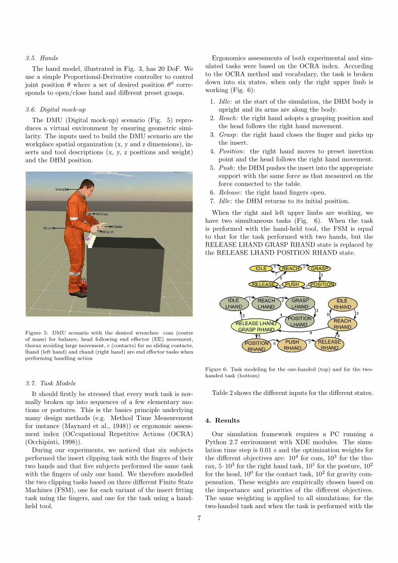
The DMU (Digital mock-up) scenario (Fig. 5) repro-duces a virtual environment by ensuring geometric simi-larity. The inputs used to build the DMU scenario are theworkplace spatial organization (x, y and z dimensions), in-serts and tool descriptions (x, y, z positions and weight)and the DHM position.
Figure 5: DMU scenario with the desired wrenches: com (centreof mass) for balance, head following end effector (EE) movement,thorax avoiding large movement, c (contacts) for no sliding contacts,lhand (left hand) and rhand (right hand) are end effector tasks whenperforming handling action
3.7. Task Models
It should firstly be stressed that every work task is nor-mally broken up into sequences of a few elementary mo-tions or postures. This is the basics principle underlyingmany design methods (e.g. Method Time Measurementfor instance (Maynard et al., 1948)) or ergonomic assess-ment index (OCcupational Repetitive Actions (OCRA)(Occhipinti, 1998)).
During our experiments, we noticed that six subjectsperformed the insert clipping task with the fingers of theirtwo hands and that five subjects performed the same taskwith the fingers of only one hand. We therefore modelledthe two clipping tasks based on three different Finite StateMachines (FSM), one for each variant of the insert fittingtask using the fingers, and one for the task using a hand-held tool.
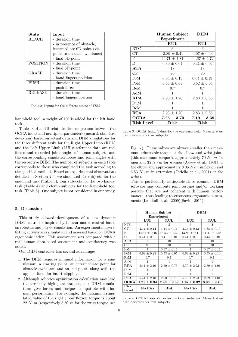
Ergonomics assessments of both experimental and sim-ulated tasks were based on the OCRA index. Accordingto the OCRA method and vocabulary, the task is brokendown into six states, when only the right upper limb isworking (Fig. 6):
1. Idle: at the start of the simulation, the DHM body isupright and its arms are along the body.
2. Reach: the right hand adopts a grasping position andthe head follows the right hand movement.
3. Grasp: the right hand closes the finger and picks upthe insert.
4. Position: the right hand moves to preset insertionpoint and the head follows the right hand movement.
5. Push: the DHM pushes the insert into the appropriatesupport with the same force as that measured on theforce connected to the table.
6. Release: the right hand fingers open.
7. Idle: the DHM returns to its initial position.
When the right and left upper limbs are working, wehave two simultaneous tasks (Fig. 6). When the taskis performed with the hand-held tool, the FSM is equalto that for the task performed with two hands, but theRELEASE LHAND GRASP RHAND state is replaced bythe RELEASE LHAND POSITION RHAND state.
Figure 6: Task modeling for the one-handed (top) and for the two-handed task (bottom)
Table 2 shows the different inputs for the different states.
4. Results
Our simulation framework requires a PC running aPython 2.7 environment with XDE modules. The simu-lation time step is 0.01 s and the optimization weights forthe different objectives are: 104 for com, 103 for the tho-rax, 5 ·103 for the right hand task, 101 for the posture, 102
for the head, 100 for the contact task, 102 for gravity com-pensation. These weights are empirically chosen based onthe importance and priorities of the different objectives.The same weighting is applied to all simulations; for thetwo-handed task and when the task is performed with the
7
State Input
REACH - duration time- in presence of obstacle,intermediate 6D point (viapoint to obstacle avoidance)- final 6D point
POSITION - duration time- final 6D point
GRASP - duration time- hand fingers position
PUSH - duration time- push force
RELEASE - duration time- hand fingers position
Table 2: Inputs for the different states of FSM
hand-held tool, a weight of 103 is added for the left handtask.
Tables 3, 4 and 5 relate to the comparison between theOCRA index and multiplier parameters (mean ± standarddeviation) based on actual data and DHM simulations forthe three different tasks for the Right Upper Limb (RUL)and the Left Upper Limb (LUL): reference data are realforces and recorded joint angles of human subjects andthe corresponding simulated forces and joint angles withthe respective DHM. The number of subjects in each tablecorresponds to those who completed the task according tothe specified method. Based on experimental observationsdetailed in Section 2.6, we simulated six subjects for theone-hand-task (Table 3), four subjects for the two-hands-task (Table 4) and eleven subjects for the hand-held tooltask (Table 5). One subject is not considered in our study.
5. Discussion
This study allowed development of a new dynamicDHM controller inspired by human motor control basedon robotics and physic simulation. An experimental insert-fitting activity was simulated and assessed based on OCRAergonomic index. This assessment was compared with areal human data-based assessment and consistency wasnoted.
Our DHM controller has several advantages:
1. The DHM requires minimal information for a sim-ulation: a starting point, an intermediate point forobstacle avoidance and an end point, along with theapplied force for insert clipping.
2. Although robotics optimization calculation may leadto extremely high joint torques, our DHM simula-tions give forces and torques compatible with hu-man performance. For example, the maximum simu-lated value of the right elbow flexion torque is about22 N ·m (respectively 5 N ·m for the wrist torque, see
Human Subject DHM
Experiment
RUL RUL
NTC 3 3CT 3.89 ± 0.41 4.07 ± 0.43F 46.71 ± 4.87 44.67 ± 4.72D 0.39 ± 0.04 0.41 ± 0.04ATA 18 18CF 30 30FoM 0.64 ± 0.19 0.64 ± 0.19PoM 0.55 ± 0.08 0.52 ± 0.04ReM 0.7 0.7AdM 1 1RPA 2.93 ± 1.20 2.83 ± 0.85DuM 1 1RcM 1 1RTA 2.93 ± 1.20 2.83 ± 0.85OCRA 7.25 ± 3.70 7.19 ± 3.39
Risk Level Risk Risk
Table 3: OCRA Index Values for the one-hand-task. Mean ± stan-dard deviation for six subjects
Fig. 7). These values are always smaller than maxi-mum admissible torque at the elbow and wrist joints(this maximum torque is approximately 70 N ·m formen and 35 N ·m for women (Askew et al., 1981) atthe elbow and approximately 8.05 N ·m in flexion and6.53 N · m in extension (Ciriello et al., 2001) at thewrist).This is particularly noticeable since common DHMsoftware may compute joint torques and/or workingposture that are not coherent with human perfor-mances, thus leading to erroneous ergonomic assess-ments (Lamkull et al., 2009)(Savin, 2011).
Human Subject DHM
Experiment
LUL RUL LUL RUL
NTC 1 3 3 2CT 4.14 ± 0.14 4.14 ± 0.14 4.35 ± 0.13 4.35 ± 0.13F 14.51 ± 0.46 43.53 ± 1.39 13.80 ± 0.41 41.41 ± 1.23D 0.41 ± 0.01 0.41 ± 0.01 0.44 ± 0.01 0.44 ± 0.01ATA 6 18 6 18CF 30 30 30 30FoM 1 0.57 ± 0.15 1 0.57 ± 0.15PoM 0.63 ± 0.25 0.53 ± 0.05 0.63 ± 0.25 0.55 ± 0.10ReM 0.7 0.7 0.7 0.7AdM 1 1 1 1RPA 5.41 ± 2.10 2.60 ± 0.73 5.70 ± 2.23 2.89 ± 1.01DuM 1 1 1 1RcM 1 1 1 1RTA 5.41 ± 2.10 2.60 ± 0.73 5.70 ± 2.23 2.89 ± 1.01OCRA 1.21 ± 0.34 7.46 ± 2.62 1.15 ± 0.32 6.93 ± 2.78
RiskNo Risk Risk No Risk Risk
Level
Table 4: OCRA Index Values for the two-hands-task. Mean ± stan-dard deviation for four subjects
8
Human Subject DHM
Experiment
LUL RUL LUL RUL
NTC 1 3 3 2CT 3.99 ± 0.37 3.99 ± 0.37 4.14 ± 0.35 4.14 ± 0.35F 30.28 ± 2.88 30.28 ± 2.88 29.17 ± 2.56 29.17 ± 2.56D 0.40 ± 0.04 0.40 ± 0.04 0.41 ± 0.03 0.41 ± 0.03ATA 12 12 12 12CF 30 30 30 30FoM 1 0.87 ± 0.14 1 0.87 ± 0.14PoM 0.61 ± 0.16 0.52 ± 0.04 0.61 ± 0.16 0.51 ± 0.03ReM 0.7 0.7 0.7 0.7AdM 1 1 1 1RPA 5.12 ± 1.43 3.76 ± 0.74 5.30 ± 1.44 3.82 ± 0.61DuM 1 1 1 1RcM 1 1 1 1RTA 5.12 ± 1.43 3.76 ± 0.74 5.30 ± 1.44 3.82 ± 0.61OCRA 2.49 ± 0.61 3.30 ± 0.67 2.40 ± 0.57 3.23 ± 0.61
Risk Very Low Very Low Very Low Very Low
Level Risk Risk Risk Risk
Table 5: OCRA Index Values for the tool-task. Mean ± standarddeviation for all subjects
3. Our controller can solve simulations including noncoplanar contacts, friction and dynamics. It achievesthe best available robustness to external perturba-tions. It can solve the whole control problem in oneprocedure in quasi real time to find the optimal so-lution with respect to all the considered criteria. Forour simulation, computation time is 1.5 times longerthan time step.
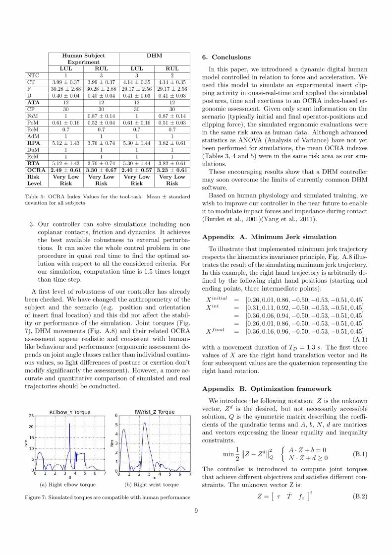
A first level of robustness of our controller has alreadybeen checked. We have changed the anthropometry of thesubject and the scenario (e.g. position and orientationof insert final location) and this did not affect the stabil-ity or performance of the simulation. Joint torques (Fig.7), DHM movements (Fig. A.8) and their related OCRAassessment appear realistic and consistent with human-like behaviour and performance (ergonomic assessment de-pends on joint angle classes rather than individual continu-ous values, so light differences of posture or exertion don’tmodify significantly the assessment). However, a more ac-curate and quantitative comparison of simulated and realtrajectories should be conducted.
(a) Right elbow torque (b) Right wrist torque
Figure 7: Simulated torques are compatible with human performance
6. Conclusions
In this paper, we introduced a dynamic digital humanmodel controlled in relation to force and acceleration. Weused this model to simulate an experimental insert clip-ping activity in quasi-real-time and applied the simulatedpostures, time and exertions to an OCRA index-based er-gonomic assessment. Given only scant information on thescenario (typically initial and final operator-positions andclipping force), the simulated ergonomic evaluations werein the same risk area as human data. Although advancedstatistics as ANOVA (Analysis of Variance) have not yetbeen performed for simulations, the mean OCRA indexes(Tables 3, 4 and 5) were in the same risk area as our sim-ulations.
These encouraging results show that a DHM controllermay soon overcome the limits of currently common DHMsoftware.
Based on human physiology and simulated training, wewish to improve our controller in the near future to enableit to modulate impact forces and impedance during contact(Burdet et al., 2001)(Yang et al., 2011).
Appendix A. Minimum Jerk simulation
To illustrate that implemented minimum jerk trajectoryrespects the kinematics invariance principle, Fig. A.8 illus-trates the result of the simulating minimum jerk trajectory.In this example, the right hand trajectory is arbitrarily de-fined by the following right hand positions (starting andending points, three intermediate points):
Xinitial = [0.26, 0.01, 0.86,−0.50,−0.53,−0.51, 0.45]Xint = [0.31, 0.11, 0.92,−0.50,−0.53,−0.51, 0.45]
= [0.36, 0.06, 0.94,−0.50,−0.53,−0.51, 0.45]= [0.26, 0.01, 0.86,−0.50,−0.53,−0.51, 0.45]
Xfinal = [0.36, 0.16, 0.96,−0.50,−0.53,−0.51, 0.45](A.1)
with a movement duration of TD = 1.3 s. The first threevalues of X are the right hand translation vector and itsfour subsequent values are the quaternion representing theright hand rotation.
Appendix B. Optimization framework
We introduce the following notation: Z is the unknownvector, Zd is the desired, but not necessarily accessiblesolution, Q is the symmetric matrix describing the coeffi-cients of the quadratic terms and A, b, N , d are matricesand vectors expressing the linear equality and inequalityconstraints.
min1
2
∥
∥Z − Zd∥
∥
2
Q
{
A · Z + b = 0N · Z + d ≥ 0
(B.1)
The controller is introduced to compute joint torquesthat achieve different objectives and satisfies different con-straints. The unknown vector Z is:
Z =[
τ T fc]t
(B.2)
9
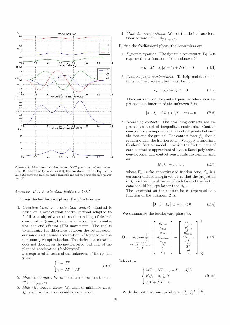
Figure A.8: Minimum jerk simulation. XYZ positions (A) and veloc-ities (B); the velocity modules (C); the constant c of the Eq. (7) tovalidate that the implemented minjerk model respects the 2/3 powerlaw (D)
Appendix B.1. Acceleration feedforward QP
During the feedforward phase, the objectives are:
1. Objective based on acceleration control. Control isbased on a acceleration control method adapted tofulfill task objectives such as the tracking of desiredcom position (com), thorax orientation, head orienta-tion and end effector (EE) movements. The goal isto minimize the difference between the actual accel-eration a and desired acceleration ad founded by theminimum jerk optimization. The desired accelerationdoes not depend on the motion error, but only of theplanned acceleration (feedforward).a is expressed in terms of the unknowns of the systemT as:
{
v = JT
a = JT + JT(B.3)
2. Minimize torques. We set the desired torques to zero.τdacc = 0(ndof ,1)
3. Minimize contact forces. We want to minimize fc, sofdc is set to zero, as it is unknown a priori.
4. Minimize accelerations. We set the desired accelera-tions to zero. T d = 0(6+ndof ,1)
During the feedforward phase, the constraints are:
1. Dynamic equation. The dynamic equation in Eq. 4 isexpressed as a function of the unknown Z:
[−L M J tc ]Z + (γ +NT ) = 0 (B.4)
2. Contact point accelerations. To help maintain con-tacts, contact acceleration must be null.
ac = JcT + JcT = 0 (B.5)
The constraint on the contact point accelerations ex-pressed as a function of the unknown Z is:
[0 Jc 0]Z + (JcT − adc) = 0 (B.6)
3. No-sliding contacts. The no-sliding contacts are ex-pressed as a set of inequality constraints. Contactconstraints are imposed at the contact points betweenthe foot and the ground. The contact force fcj shouldremain within the friction cone. We apply a linearizedCoulomb friction model, in which the friction cone ofeach contact is approximated by a n faced polyhedralconvex cone. The contact constraints are formularizedas:
Ecifci + dci < 0 (B.7)
where Eci is the approximated friction cone, dci is acustomer defined margin vector, so that the projectionof fci on the normal vector of each facet of the frictioncone should be kept larger than dci .
The constraint on the contact forces expressed as afunction of the unknown Z is:
[0 0 Ec] Z + dc < 0 (B.8)
We summarize the feedforward phase as:
O = arg min1
2acom,aEE ,
ahead,athorax,
fcj ,T
∥
∥
∥
∥
∥
∥
∥
∥
∥
∥
∥
∥
∥
∥
acomaEE
aheadathoraxτaccTfcj
−
adcomadEE
adheadadthoraxτdaccT d
fdcj
∥
∥
∥
∥
∥
∥
∥
∥
∥
∥
∥
∥
∥
∥
2
Q
(B.9)
Subject to:
MT +NT + γ = Lτ − J tcfc
Ecfc + dc ≥ 0
JcT + JcT = 0
(B.10)
With this optimization, we obtain τffacc, fffc , T ff .
10
Appendix B.2. Force feedback QP
The unknown vector Z is:
Z=[
WEE Fcom Γthorax Γhead τposture ∆fc]t
(B.11)During the feedback phase the objectives are:
1. Force control-based. This control is introduced to cor-rect the movement on the fly. Furthermore, it allow usto handle contacts during the manipulation by settingthe desired contact forces. Given a desired wrenchW d
in the Cartesian coordinate space, the equivalent jointtorques τ can be obtained by means of the principleof the virtual works τ = J tW d, with J the Jacobianmatrix at the point where W d is supposed to be ap-plied. The goal of our control system is to computejoint torques based on given tasks. For each task,we imagine that a virtual wrench W d is applied at acertain point on the body of the DHM to guide itsmotion (Fig. 5). We define the desired wrench usinga proportional-derivative (PD) feedback control law:
W d = Kδ(Hd, Hr) +Dδ(V d, V r) +W ff (B.12)
with Hr ∈ SE(3), Hd ∈ SE(3), V r ∈ se(3) and V d ∈se(3), where SE(3) is the special Euclidean group andse(3) is the Lie algebra of SE(3). δ(Hd, Hr) standsfor error between the desired and the current positionand orientation, while δ(V d, V r) stands for error be-tween the desired and the current linear and angularvelocities. K and D are the proportional and deriva-tive gain matrix respectively. For the com task onlythe position error is considered, while for thorax andhead tasks only the orientation error are considered.An additional W ff can be added, if a contact is es-tablished the end effector and an object during thehandling.This anticipatory feedforward force helps to improvecontact between the end effector and the object. Itcan be defined based on the physical characteristic ofthe object, such as the weight and the friction coeffi-cient.
2. Posture. The difference between the actual jointtorque τposture and the desired joint torque τdpostureis minimized. τdposture can be written as:
τdposture = Ke+De (B.13)
with e joint position error and e joint velocity error.3. Minimize contact forces. ∆fd
c = 0(3nfc ,1)with
Q∆fc = w∆fcI3nfc
During feedback phase the constraints are:
1. Static equilibrium of rigid body mode. The wrenchesare constrained by the static equilibrium of the rootbody:
0=Jrootcom
tFcom + Jroot
thoraxtΓthorax + Jroot
headtΓhead
+ JrootEE
tWEE + Jroot
ct∆fci
(B.14)
2. No-sliding contact
Ec(fffc +∆fc) + dc ≥ 0 (B.15)
We summarize the feedback phase as:
O = arg min1
2Fcom,Wt,
Γthorax,Γhead,τposture,∆fcj
∥
∥
∥
∥
∥
∥
∥
∥
∥
∥
∥
∥
Fcom
WEE
Γthorax
Γhead
τposture∆fcj
−
F dcom
W dEE
Γdthorax
Γdhead
τdposture∆fd
cj
∥
∥
∥
∥
∥
∥
∥
∥
∥
∥
∥
∥
2
Q
(B.16)Subject to:
0=Jrootcom
tFcom + Jroot
thoraxtΓthorax + Jroot
thoraxtΓhead
+ JrootEE
tWEE + Jroot
ct∆fci
Ec(fffc +∆fc) + dc ≥ 0
(B.17)The feedback joint torque can be obtained by:
τfb = J tcomFcom + J t
thoraxΓthorax + J theadΓhead
+ J tEEWEE + J t
c∆fc + τposture(B.18)
At the end of the feedforward and feedback phases we ob-tain respectively τff and τfb. The joint torques applied tothe DHM is equal to:
τ = τff + τfb (B.19)
References
Abe, Y., da Silva, M., Popovic, J., 2007. Multiobjective control withfrictional contacts. In: Proc. ACM SIGGRAPH/EG Symposiumon Computer Animation. Aire-la-Ville, Switzerland, pp. 249–258.
AFNOR, 2003. Nf en 1005-2 safety of machinery human physicalperformance - part 2: Manual handling of machinery and compo-nents parts of machinery. AFNOR (La Plaine St-Denis).
AFNOR, 2007. Nf en 1005-5 safety of machinery human physicalperformance - part 5: Risk assessment for repetitive handling athigh frequency. AFNOR (La Plaine St-Denis).
AFNOR, 2008. Nf en 1005-5 - safety of machinery - human physicalperformance - part 4: Evaluation of working postures and move-ments in relation to machinery. AFNOR (La Plaine St-Denis).
Askew, L. J., An, K. N., Morrey, B. F., Chao, E. Y., 1981. Functionalevaluation of the elbow. normal motion requirements and strengthdeterminations. Orthop. Trans., 5–304.
Badler, N. I., 1997. Virtual humans for animation, ergonomics, andsimulation. In: Proceedings of the IEEE workshop on non-rigidand articulates motion. pp. 28–36.
Bernard, B. P., 1997. Musculoskeletal Disorders and Workplace Fac-tors. A Critical Review of Epidemiologic Evidence for Work-Related Musculoskeletal Disorders of the Neck, Upper Extremity,and Low Back. NIOSH.
Bradwell, B., Li, B., 2008. A tutorial on motion capture driven char-acter animation. In: Eight IASTED International Conference Vi-sualization, Imagin, and Image Processing. Palma de Mallorca.
Bretl, T., Lall, S., 2008. Testing static equilibrium for legged robots.IEEE Transactions on Robotics 24, 794–807.
Burdet, E., Osu, R., Franklin, D. W., Milner, T. E., Kawato, M.,2001. The central nervous system stabilizes unstable dynamics bylearning optimal impedance. Nature 414, 446–449.
11

CEN, 2008. Safety of machinery - anthropometric requirements forthe design of workstations at machinery. European standard ENISO 14738:2008.
Chaffin, D. B., 2005. Improving digital human modelling for proac-tive ergonomics in design. Ergonomics 48, 478–491.
Chaffin, D. B., 2007. Human motion simulation for vehicle and work-place design. Human Factors and Ergonomics in Manufacturing17, 475–484.
Ciriello, V. M., Snook, S. H., Webster, B. S., Dempsey, P., 2001.Psychophysical study of six hand movements. Ergonomics 44, 922–936.
Colette, C., Micaelli, A., Andriot, C., Lemerle, P., 2008. Robustbalance optimization control of humanoid robots with multiplenon coplanar grasps and frictional contacts. In: Proceedings ofthe IEEE International Conference on Robotics and Automation.Pasadena, USA, pp. 3187–3193.
DeMagistris, G., Micaelli, A., Andriot, C., Savin, J., Marsot, J.,2011. Dynamic virtual manikin control design for the assessmentof the workstation ergonomy. In: First International Symposiumon Digital Human Modeling. Lyon.
Dukic, T., Ronang, M., Christmansson, M., 2007. Evaluation of er-gonomics in a virtual manufacturing process. Journal of Engineer-ing Design 18, 125–137.
EU, 2006. Eu directive on machinery - directive 2006/42/ec ofthe european parliament and of the council of 17 may 2006 onmachinery. Official Journal of the European Union.URL http://eur-lex.europa.eu/LexUriServ/LexUriServ.do?
uri=OJ:L:2006:157:0024:0086:EN:PDF
Fitts, P. M., 1954. The information capacity of the human motorsystem in controlling the amplitude of movement. Journal of Ex-perimental Pshychology 47, 381–391.
Flash, T., Hogan, N., 1985. The coordination of arm movements: anexperimentally confirmed mathematical model. Journal of Neuro-science 7, 1688–1703.
Gaudez, C., 2008. Upper limb musculo-skeletal disorders and insertfitting activity in automobile sector: impact on muscular stressesof fitting method and insert position on part. In: Computer Meth-ods in Biomechanics and Biomedical Engineering. Vol. 11. pp.101–102.
Gomes, S., Sagot, J. C., Koukam, A., Leroy, N., 1999. Manercos, anew tool providing ergonomics in a concurrent engineering designlife cycle. In: 4th Annual Scientific Conference on Web Technol-ogy, New Media, communications and Telematics. Theory, Meth-ods, Tools and Applications, EUROMEDIA 99. Munich, pp. 237–241.
Gribble, P. L., Ostry, D. J., 1999. Compensation for interactiontorques during single and multijoint limb movement. Journal ofNeurophysiology 82, 2310–2326.
Hanavan, E. P., 1964. A mathematical model of the human body.Wright-Patterson Air Force Base Report No. AMRL-TR-102, 64–102.
Hignett, S., MacAtamney, L., 2000. Rapid entire body assessment(reba). Applied Ergonomics 31, 201–205.
Hyman, R., 1953. Stimulus information as a determinant of reactiontime. Journal of Experimental Psychology 45, 188–196.
Kao, S. Y., 2003. Carpal tunnel syndrome as an occupational disease.Journal of the American board of family medicine 16, 533–542.
Kawato, M., Gomi, H., 1992. A computational model of four regionsof the cerebellum based on feedback error learning. Biological Cy-bernetics 69, 95–103.
Lackner, J. R., Dizio, P., 1994. Rapid adaptation to coriolis forceperturbations of arm trajectory. Journal of Neurophysiology 72,299–313.
Lamkull, D., Hanson, L., Ortengren, R., 2009. A comparative studyof digital human modelling simulation results and their outcomesin reality: A case study within manual assembly of automobiles.International Journal of Industrial Ergonomics 39, 428–441.
Liu, M., Micaelli, A., Evrard, P., Escande, A., Andriot, C., 2011. In-teractive dynamics and balance of a virtual character during ma-nipulation tasks. In: IEEE International Conference on Roboticsand Automation. Shanghai, China, pp. 1676–1682.
MacAtamney, L., Cortlett, E. N., 1993. Rula: a survey method forthe investigation of work-related upper limb disorders. AppliedErgonomics 24, 91–99.
Maynard, H. B., Stegemerten, G. J., Schwab, J. L., 1948. Methods-time measurement. McGraw Hill book company.
Morasso, P., 1981. Spatial control of arm movements. ExperimentalBrain Research 42, 223–227.
Morasso, P., Mussa-Ivaldi, F. A., 1982. Trajectory formation andhandwriting: a computational model. Biological Cybernetics 45,131–142.
NST-n168, 1998. Ergonomie des outils a main - Problematique etetat de l’art. Note scientifique et technique de l’INRS.
Occhipinti, E., 1998. Ocra, a concise index for the assessment ofexposure to repetitive movements of the upper limbs. Ergonomics41, 1290–1311.
Porter, J. M., Case, K., Marshall, R., Gyi, D., Sims, R., 2004. Beyondjack and jill: designing for individuals using hadrian. InternationalJournal of Industrial Ergonomics 33, 249–264.
Pratt, J., Torres, A., Dilworth, P., Pratt, G., 1996. Virtual actuatorcontrol. In: IEEE International Conference on Intelligent Robotsand Systems. pp. 1219–1226.
Savin, J., August 2011. Digital human manikins for work-task er-gonomic assessment: which degree of confidence and using con-straints? Proceedings of the Institution of Mechanical Engineers,Part B: Journal of Engineering Manufacture 225, 1401–1409.
Sjogaard, G., Sejersted, O. M., Winkel, J., Smolander, J., Jorgensen,K., Westgaard, R., 1995. Exposure assessment and mechanismsof pathogenesis in work-related musculoskeletal disorders: Sig-nificant aspects in the documentation of risk factors. Work andHealth. Scientific Basis of Progress in the Working Environment,edited by O. Svane and C. Johansen.
Todorov, E., Jordan, M. I., 1998. Smoothness maximization along apredefined path accurately predicts the speed profiles of complexarm movements. Journal of Neurophysiology 80, 697–714.
Uno, Y., Kawato, M., Suzuki, R., 1989. Formation and control ofoptimal trajectory in human multijoint arm movement: Minimumtorque-change model. Biological Cybernetics 61, 89–101.
Yang, C., Ganesh, G., Haddadin, S., Parusel, S., Albu-Schaeffer, A.,Burdet, E., 2011. Human like adaptation of force and impedancein stable and unstable interactions. Transactions on Robotics 27,918–930.
12