DYNAMIC ABUTMENT SOLUTIONS LIBRARY€¦ · Then define the insertion axis, the abutment parameters...
14
INSTRUCTIONS FOR USE DYNAMIC ABUTMENT® SOLUTIONS LIBRARY INST_DW_2016_01_EN
Transcript of DYNAMIC ABUTMENT SOLUTIONS LIBRARY€¦ · Then define the insertion axis, the abutment parameters...

INSTRUCTIONS FOR USE DYNAMIC ABUTMENT® SOLUTIONS LIBRARY
INST
_DW
_201
6_01
_EN
2
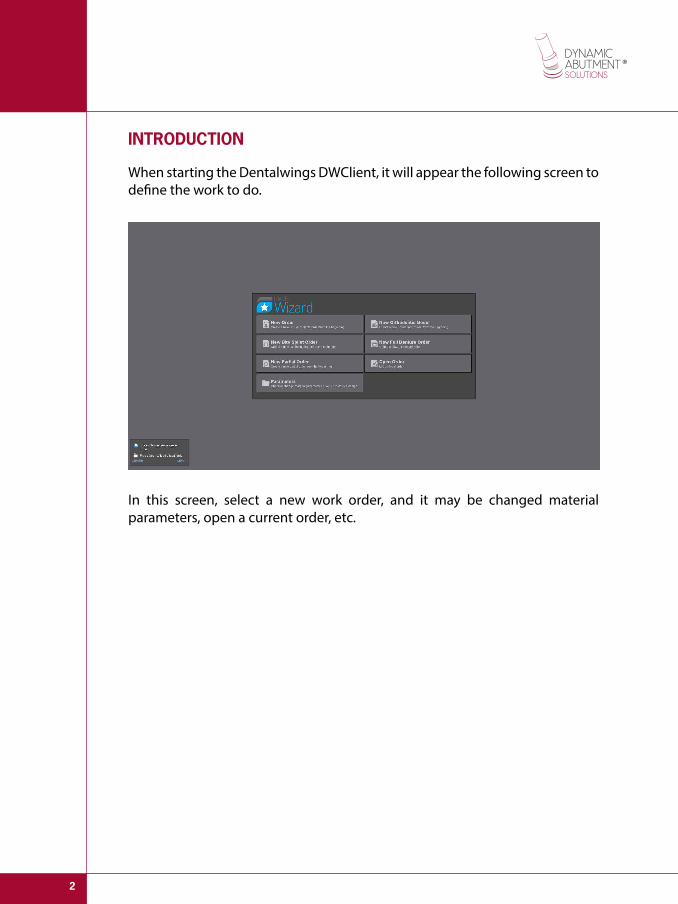
INTRODUCTION
When starting the Dentalwings DWClient, it will appear the following screen to define the work to do.
In this screen, select a new work order, and it may be changed material parameters, open a current order, etc.
3
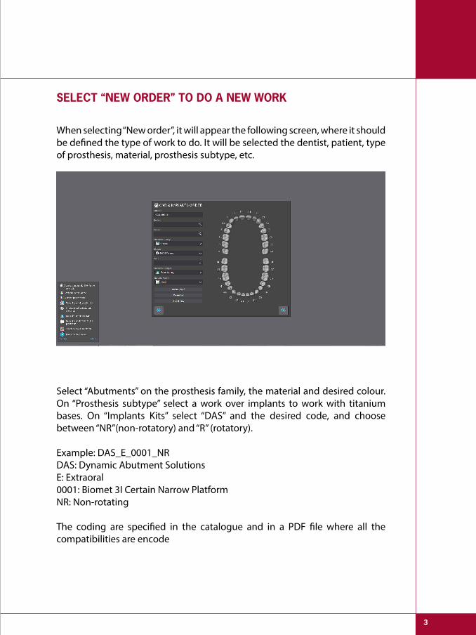
SELECT “NEW ORDER” TO DO A NEW WORK
Select “Abutments” on the prosthesis family, the material and desired colour. On “Prosthesis subtype” select a work over implants to work with titanium bases. On “Implants Kits” select “DAS” and the desired code, and choose between “NR”(non-rotatory) and “R” (rotatory).
Example: DAS_E_0001_NRDAS: Dynamic Abutment SolutionsE: Extraoral0001: Biomet 3I Certain Narrow PlatformNR: Non-rotating
The coding are specified in the catalogue and in a PDF file where all the compatibilities are encode
When selecting “New order”, it will appear the following screen, where it should be defined the type of work to do. It will be selected the dentist, patient, type of prosthesis, material, prosthesis subtype, etc.
4
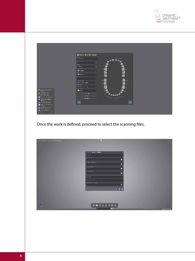
Once the work is defined, proceed to select the scanning files.

5
In the next step, it is performed the position of the scanned model.

6
Then select the zone where the scanbody is located, once selected the zone, this will stand out in a different colour and it will be the zone where look for the scanbody exact position.
Replacement zone with 3 scanbody dots.

7
Select 3 dots as it is shown in the following image. Then select the precise repositioning to finish the scanbody adjustment.

8
The cervical line is defined where the radical height, the inclination angle of the line, etc. can be modified.
Chimney angle definition
Then define the insertion axis, the abutment parameters and the angle of the screw hole.

9
As it is shown in the following image, the yellow line allows moving the chimney axis, which can be freely moved in any direction, but the chimney has to go out through the Tibase cut. Note that Ti bases can be angulated from 0 to 30° in regular and wide platforms, and from 0° to 25° in narrow platforms. This angle value can be modified also when the structure is being designed.
After it can be defined the adaptation of the surroundings, this option is similar to any kind of work
10
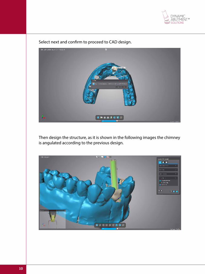
Select next and confirm to proceed to CAD design.
Then design the structure, as it is shown in the following images the chimney is angulated according to the previous design.

11
If you want to modify the angulation, select the option “Edit Margin Line”
Then select “Design parameters validation” and it will appear once again the option to modify the chimney angulation.

12
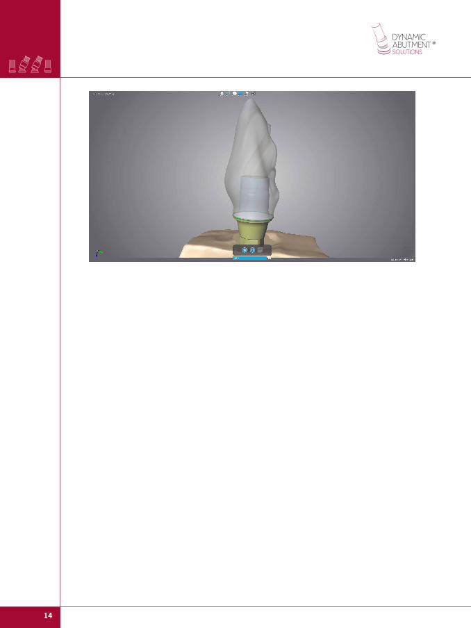
If you want you can change the angulation and proceed once again to the prosthesis final design.
Final structure design with desired angulation.
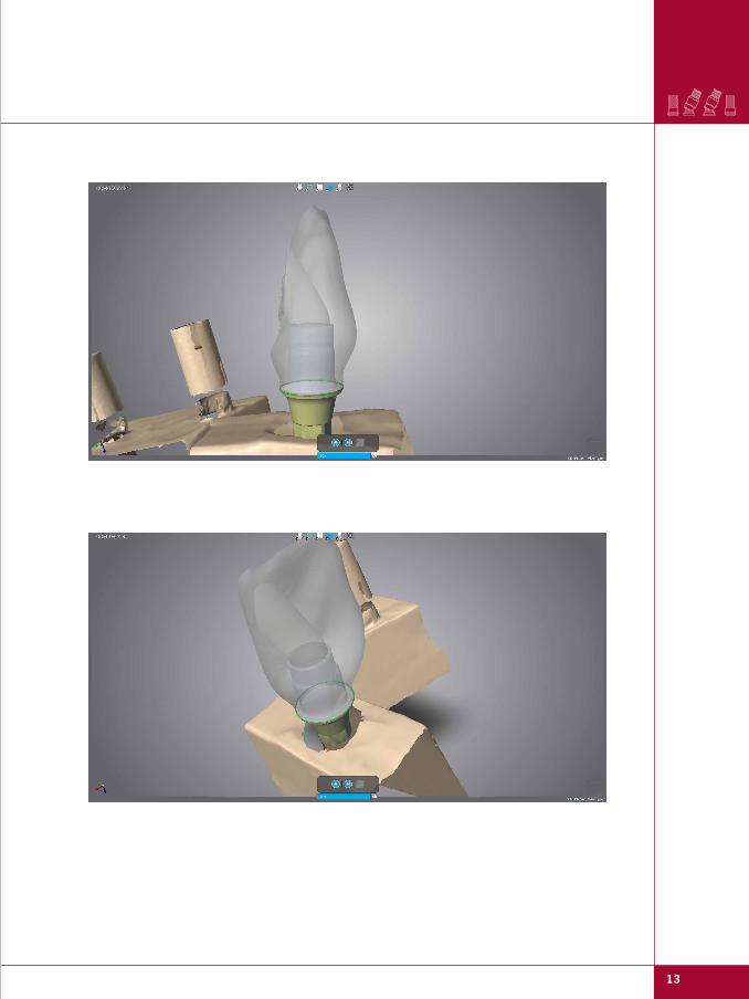
13
14


![Internal - Luciano Chinellato · AnyOne® Internal è -P_[\YL 3L]LS 7YVZ[OLZPZ EZ Post Milling Abutment Angled Abutment CCM Abutment Temporary Abutment [Titanium] Temporary Abutment](https://static.fdocuments.us/doc/165x107/5c038f7909d3f2156d8cd7fd/internal-luciano-anyone-internal-e-pyl-3lls-7yvzolzpz-ez-post-milling.jpg)