Box Abutment a1l
74
FRL = 561.936 0.35 Cl bridge (median edge) 0.3 1 15+16 4.012 2 0.775 varies cap top lvl 0.3 3 0.3 558.900 0.4 0.45 0.35 FILL 12 FILL 17.936 13 14 OGL 4 547.268 16.786 0.85 1.8 0.85 6 5 544.000 Founding level 0.3 4.662 0.3 4.7 0.85 2.3 12.419 1 10.2 0.85 10 87 ° 2.968 4.172 4.518 8 0.3 4.553 11.225 2.968 9 0.3 4.889 2.3 4.934 13.412 2.984 80 ° 0.85 11.379 0.85 4.662 5.129 11 0.863 11.507 1 2.335
-
Upload
sambhav-poddar -
Category
Documents
-
view
62 -
download
12
Transcript of Box Abutment a1l
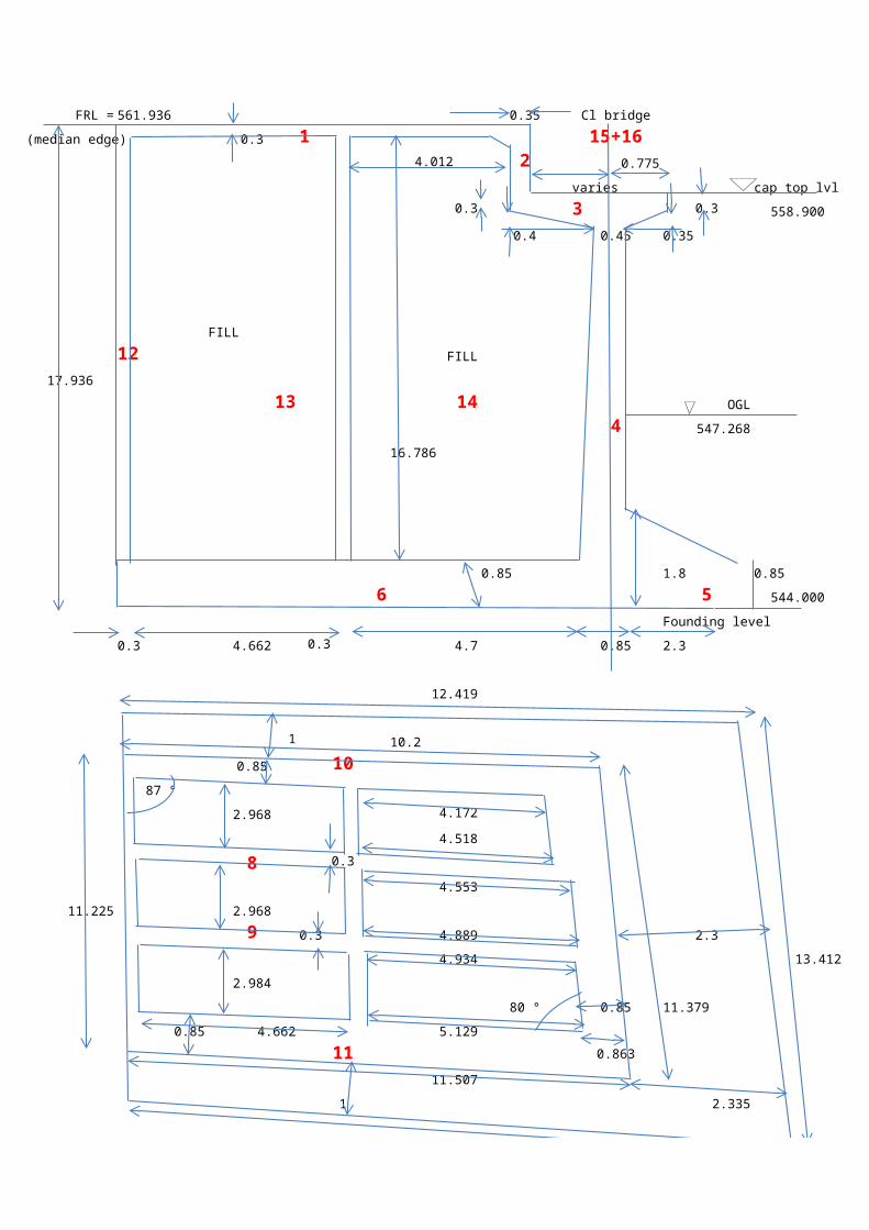
FRL = 561.936 0.35 Cl bridge
(median edge) 0.3 1 15+164.012 2 0.775
varies cap top lvl0.3 3 0.3
558.900
0.4 0.45 0.35
FILL 712 FILL
17.936
13 14 OGL
4 547.268
16.786
0.85 1.8 0.85
6 5 544.000
Founding level
0.3 4.662 0.3 4.7 0.85 2.3
12.419
110.2
0.85 1087 °
2.968 4.172
4.518
8 0.3
4.553
11.225 2.968
9 0.3 4.889 2.3
4.934 13.412
2.984
80 ° 0.85 11.379
0.85 4.662 5.129
11 0.863
11.507
1 2.335
13.959

JAMMU-UDHAMPUR V-6 (A1L + A2L)
Formation level (median edge) = 561.936
carriageway width = 11.15 m
gradient= 7 %
formation level(outer end) = 561.1560.749
wearing coat = 56 mm
height of superstructure = 1.925 m
height of pedestal = 150 mm
height of bearing = 125 mm
foundation level = 544.000
maximum height of abutment = 17.936 m0.780 m
minimum height of abutment = 17.156 m
abutment cap level = 558.900
Stem Thickness (top)= 0.450 m
Stem Thickness (bottom) = 0.850 m
maximum height of dirtwall = 3.036 m
minimum height of dirtwall = 2.256 m
DL + SIDL from superstructure = 170 t
LL from superstructure = 80 t
Allowable soil bearing capacity = 45 t/m2 (normal case)
Avg height Avg lengthcounterfort 1 16.283 m 9.415 mcounterfort 2 16.507 m 9.728 mside wall 1 16.006 m 9.794 mside wall 2 16.786 m 9.817 m
Avg height is calculated taking the average of maximum and minimum height of abutment at median and outer edge respectively and then doing the necessary deduction. Average length is the length that
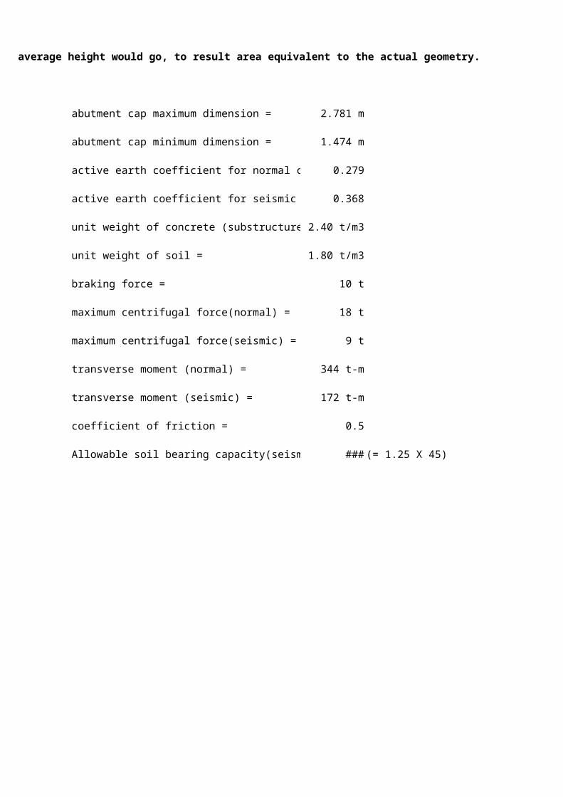
average height would go, to result area equivalent to the actual geometry.
abutment cap maximum dimension = 2.781 m
abutment cap minimum dimension = 1.474 m
active earth coefficient for normal case = 0.279
active earth coefficient for seismic case = 0.368
unit weight of concrete (substructure) = 2.40 t/m3
unit weight of soil = 1.80 t/m3
braking force = 10 t
maximum centrifugal force(normal) = 18 t
maximum centrifugal force(seismic) = 9 t
transverse moment (normal) = 344 t-m
transverse moment (seismic) = 172 t-m
coefficient of friction = 0.5
Allowable soil bearing capacity(seismic)= 56.25 t/m2 (= 1.25 X 45)

STABILITY CALCULATIONSface of dirtwall
0.574
1
0.441
face of stem wall
2 0.754
0.35
1.881
VERTICAL FORCES
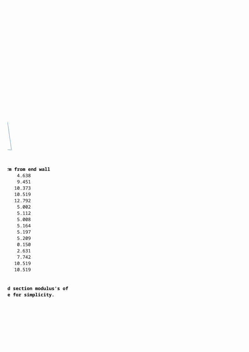
weight calculations W (t) Lever arm from end wall1 wt of slab 9.276 x 11.225 x 0.3 x 2.4 = 74.969 4.6382 dirt wall 0.5 x (2.256 + 3.036) x 11.225 x 0.35 x 2.4 = 29.754 9.4513 abut cap 0.5 x (2.781+1.474) x 11.225 x 0.6 x 2.4 = 34.389 10.3734 stem 0.5 x (0.85 + 0.45) x 17.636 x 11.379 x 2.4 = 313.061 10.5195 toe 0.5 x (1.8+0.853) x 13.412 x 2.3 x2.4 = 98.095 12.7926 heel slab 0.5 x (9.337 + 10.644) x 11.225 x 0.85 x 2.4 = 228.772 5.0027 partition wall 0.3 x 8.925 x 16.396 x 2.4 = 105.360696 5.1128 counterfort-1 0.3 x 16.283 x 9.415 x 2.4 = 110.379 5.0089 counterfort-2 0.3 x 16.507 x 9.728 x 2.4 = 115.618 5.164
10 side wall-1 0.85 x 16.006 x 9.794 x 2.4 = 319.796 5.19711 side wall-2 0.85 x 16.786 x 9.817 x 2.4 = 336.168 5.20912 end wall 0.3 x 11.225 x 16.396 x 2.4 = 132.512 0.15013 earth fill -1 41.585 x 16.396 x 1.8 = 1227.29 2.63114 earth fill-2 4.9595 x 8.92 x 16.786 x 1.8 = 1094.909 7.74215 DL + SIDL 170 = 170 10.51916 LL 80 = 80 10.519
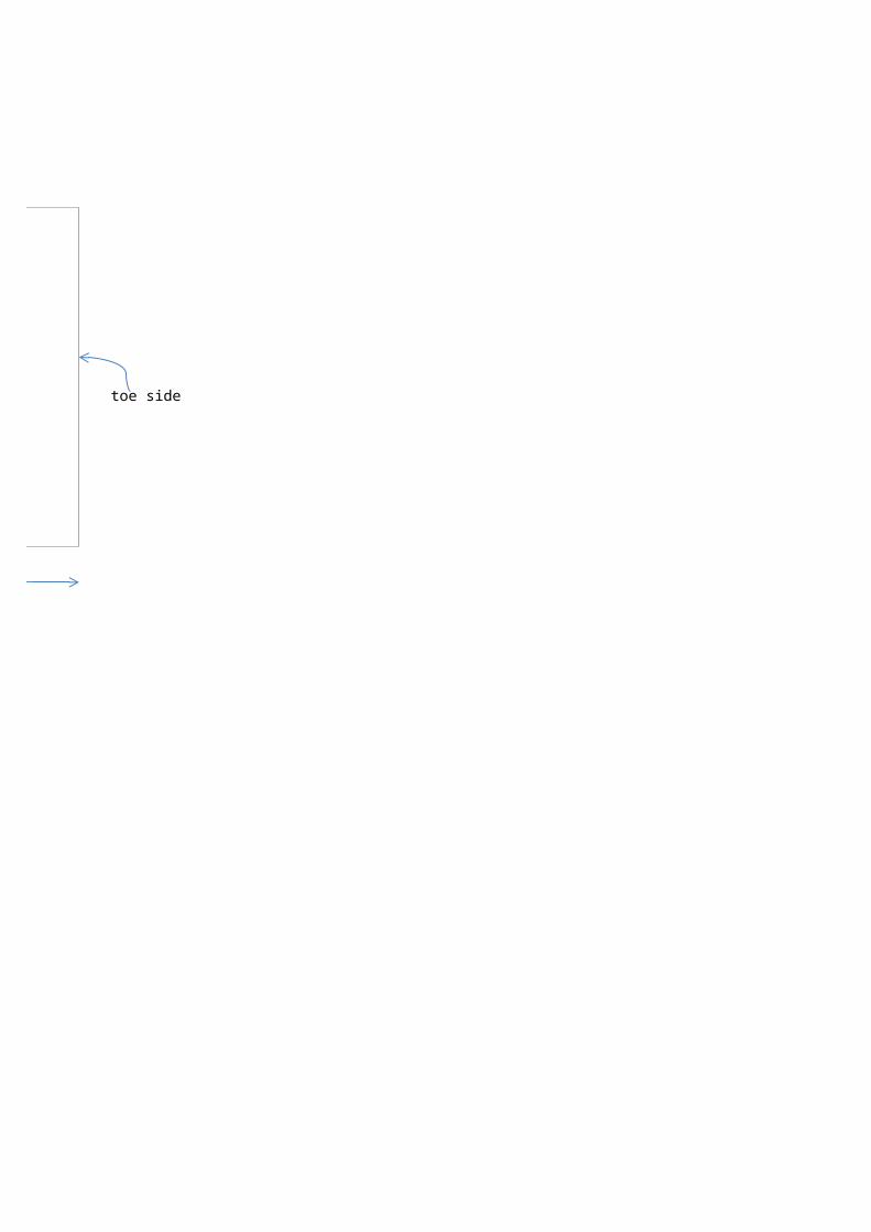
For calculating moments about toe for stability and for calculating area and section modulus's of the foundation plan, considering the trapezoid to be an equivalent rectangle for simplicity.

11.22513.225 toe side
13.189
longitudinal section modulus = 383.41 m3Area = 174.42 m2transverse section modulus = 384.46 m3
W (t) Lever arm from Toe side Moment (t-m)1 wt of slab 74.969 8.551 641.0602 dirt wall 29.754 3.738 111.2203 abut cap 34.389 2.816 96.8394 stem 313.061 2.67 835.8735 toe 98.095 0.397 38.9446 heel slab 228.772 8.187 1872.9567 partition wall 105.360696 8.077 850.9988 counterfort-1 110.379 8.181 903.0119 counterfort-2 115.618 8.025 927.834
10 side wall-1 319.796 7.992 2555.81011 side wall-2 336.168 7.980 2682.62112 end wall 132.512 13.039 1727.82413 earth fill -1 1227.29 10.558 12957.72814 earth fill-2 1094.909 5.447 5963.96915 DL + SIDL 170 2.67 453.90016 LL 80 2.67 213.600
∑ = 4471.073 32834.188

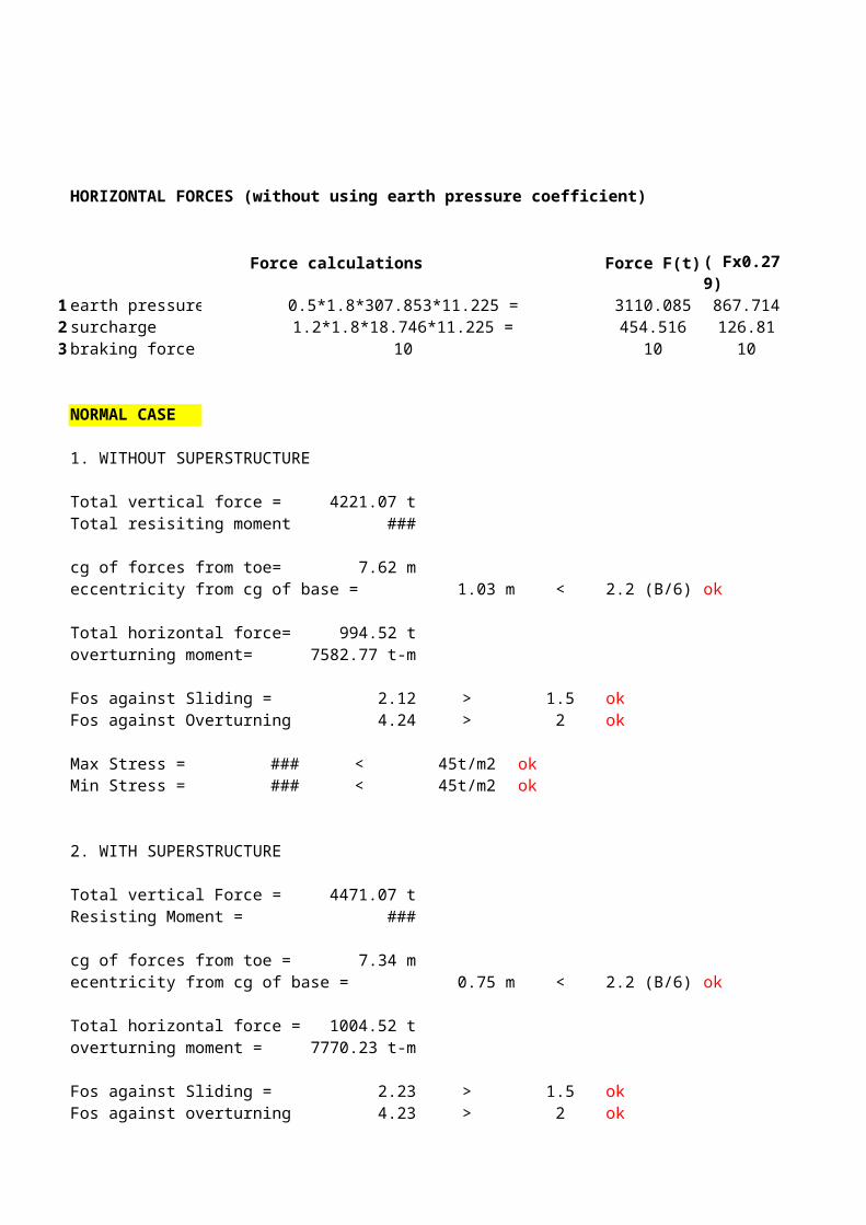
HORIZONTAL FORCES (without using earth pressure coefficient)
Force calculations Force F(t)
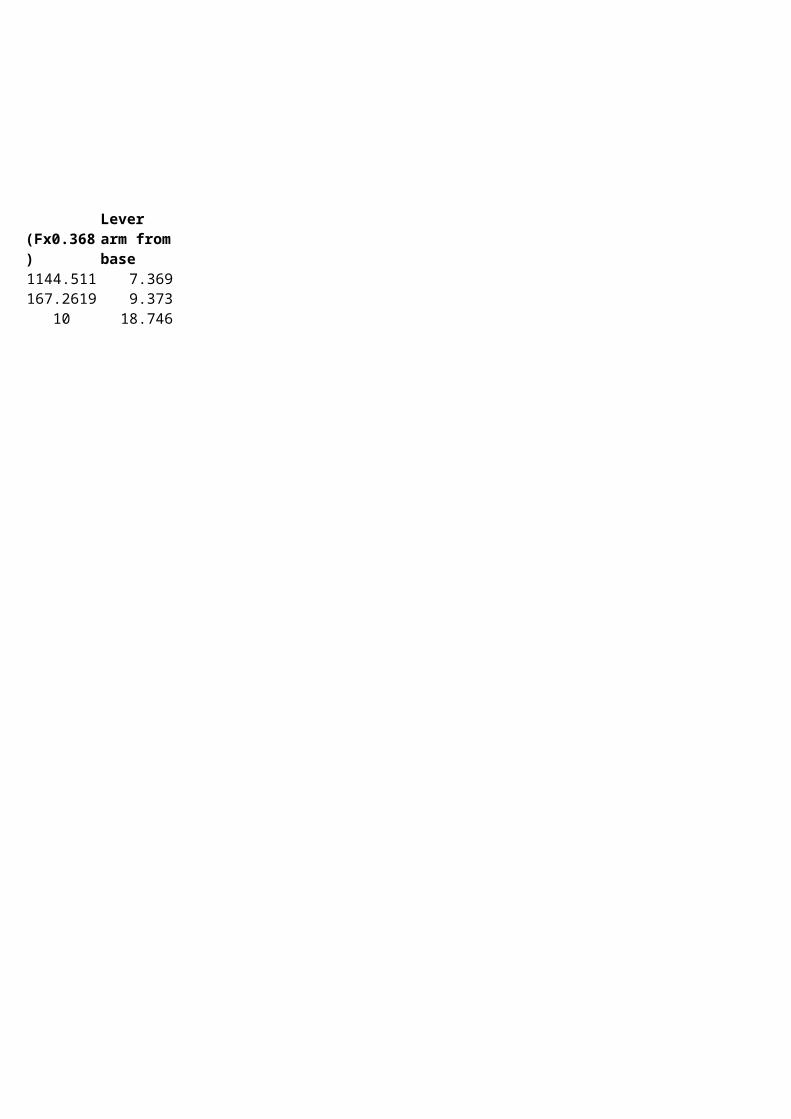
1 earth pressure 0.5*1.8*307.853*11.225 = 3110.085 867.714 1144.511 7.3692 surcharge 1.2*1.8*18.746*11.225 = 454.516 126.80996 167.2619 9.3733 braking force 10 10 10 10 18.746
NORMAL CASE
1. WITHOUT SUPERSTRUCTURE
Total vertical force = 4221.07 tTotal resisiting moment = 32166.69 t-m
cg of forces from toe= 7.62 meccentricity from cg of base = 1.03 m < 2.2 (B/6) ok
Total horizontal force= 994.52 toverturning moment= 7582.77 t-m
Fos against Sliding = 2.12 > 1.5 okFos against Overturning = 4.24 > 2 ok
Max Stress = 32.68 t/m2 < 45t/m2 okMin Stress = 15.72 t/m2 < 45t/m2 ok
2. WITH SUPERSTRUCTURE
Total vertical Force = 4471.07 tResisting Moment = 32834.19 t-m
cg of forces from toe = 7.34 mecentricity from cg of base = 0.75 m < 2.2 (B/6) ok
Total horizontal force = 1004.52 toverturning moment = 7770.23 t-m
Fos against Sliding = 2.23 > 1.5 okFos against overturning = 4.23 > 2 ok
Normal ( Fx0.279)
Seismic (Fx0.368)
Lever arm from base
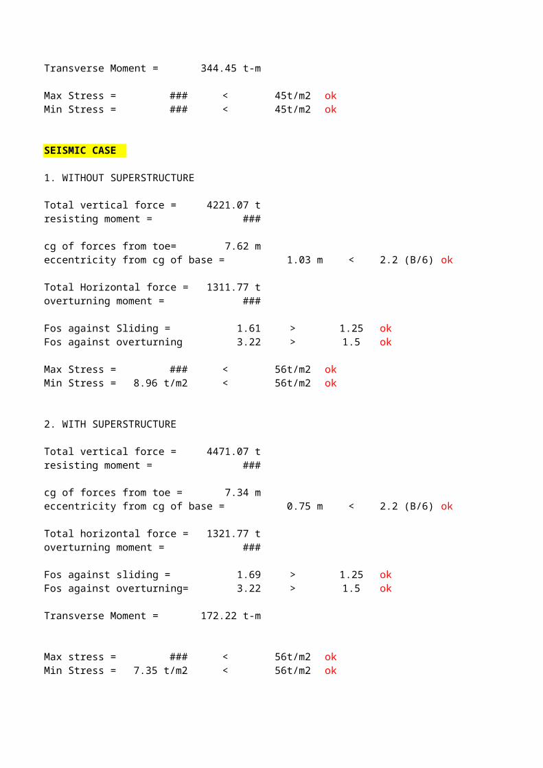
Transverse Moment = 344.45 t-m
Max Stress = 38.06 t/m2 < 45t/m2 okMin Stress = 13.21 t/m2 < 45t/m2 ok
SEISMIC CASE
1. WITHOUT SUPERSTRUCTURE
Total vertical force = 4221.07 tresisting moment = 32166.69 t-m
cg of forces from toe= 7.62 meccentricity from cg of base = 1.03 m < 2.2 (B/6) ok
Total Horizontal force = 1311.77 toverturning moment = 10001.65 t-m
Fos against Sliding = 1.61 > 1.25 okFos against overturning = 3.22 > 1.5 ok
Max Stress = 39.44 t/m2 < 56t/m2 okMin Stress = 8.96 t/m2 < 56t/m2 ok
2. WITH SUPERSTRUCTURE
Total vertical force = 4471.07 tresisting moment = 32834.19 t-m
cg of forces from toe = 7.34 meccentricity from cg of base = 0.75 m < 2.2 (B/6) ok
Total horizontal force = 1321.77 toverturning moment = 10189.11 t-m
Fos against sliding = 1.69 > 1.25 okFos against overturning= 3.22 > 1.5 ok
Transverse Moment = 172.22 t-m
Max stress = 43.92 t/m2 < 56t/m2 okMin Stress = 7.35 t/m2 < 56t/m2 ok
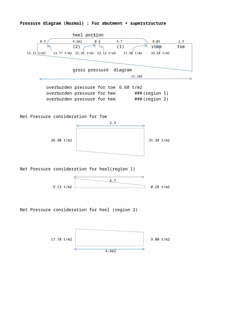
Pressure diagram (Normal) : For abutment + superstructure
heel portion0.3 4.662 0.3 4.7 0.85 2.3
(2) (1) stem toe13.21 t/m2 13.77 t/m2 22.56 t/m2 23.12 t/m2 31.98 t/m2 33.58 t/m2
gross pressure diagram 38.06 t/m2
13.189
overburden pressure for toe : 6.68 t/m2overburden pressure for heel: 32.25 t/m2 (region 1)overburden pressure for heel: 31.55 t/m2 (region 2)
Net Pressure consideration for Toe2.3
26.90 t/m2 31.38 t/m2
Net Pressure consideration for heel(region 1)
4.7
9.13 t/m2 0.28 t/m2
Net Pressure consideration for heel (region 2)
17.78 t/m2 9.00 t/m2
4.662
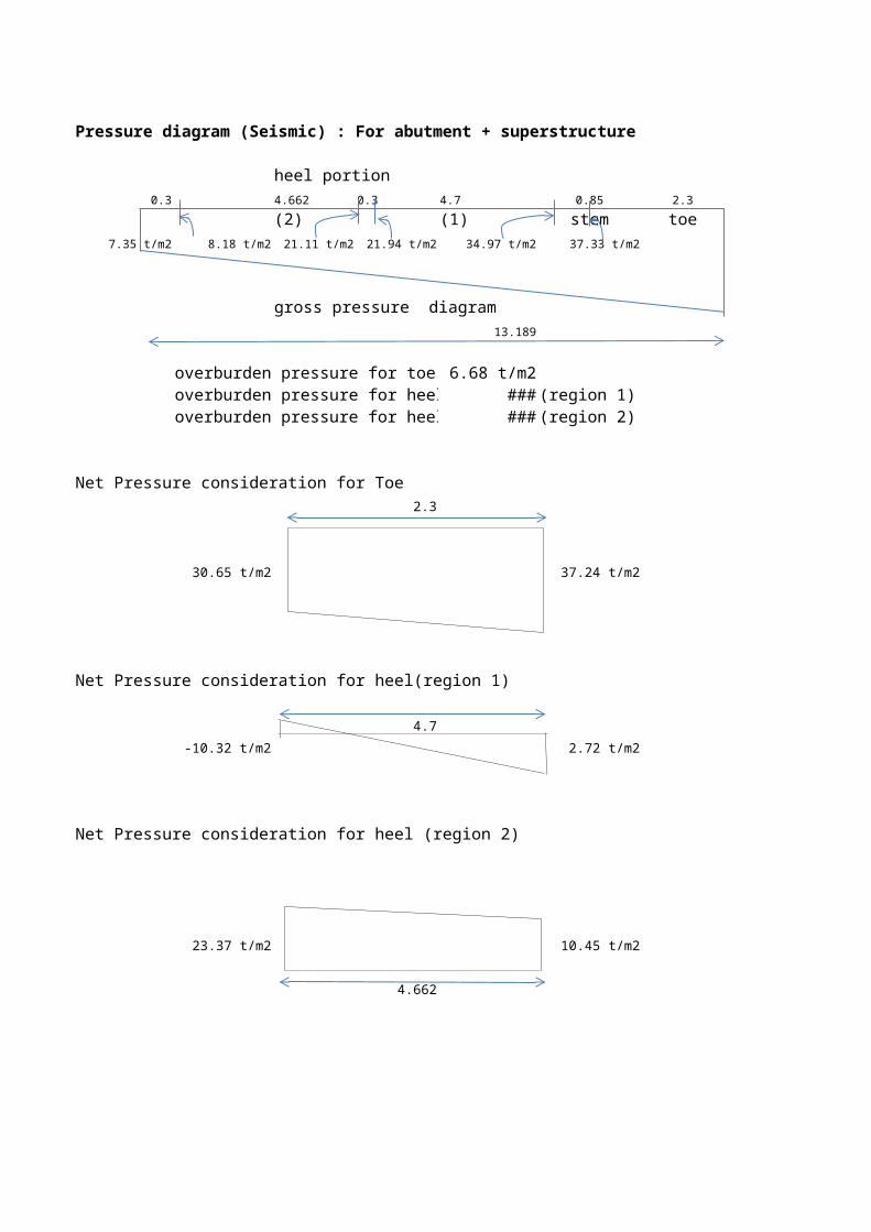
Pressure diagram (Seismic) : For abutment + superstructure
heel portion0.3 4.662 0.3 4.7 0.85 2.3
(2) (1) stem toe7.35 t/m2 8.18 t/m2 21.11 t/m2 21.94 t/m2 34.97 t/m2 37.33 t/m2
gross pressure diagram 43.92 t/m2
13.189
overburden pressure for toe : 6.68 t/m2overburden pressure for heel: 32.25 t/m2 (region 1)overburden pressure for heel: 31.55 t/m2 (region 2)
Net Pressure consideration for Toe2.3
30.65 t/m2 37.24 t/m2
Net Pressure consideration for heel(region 1)
4.7
-10.32 t/m2 2.72 t/m2
Net Pressure consideration for heel (region 2)
23.37 t/m2 10.45 t/m2
4.662
DESIGN OF TOE(NORMAL CASE)2.3
26.90 t/m2 31.38 t/m2
1.713 m 30.2 t/m2
Grade of conc. 35
Grade of steel 500
Dia of bar used 25
Q for concrete grade used 170 t/m2
k value for concrete 0.327
j value for concrete 0.891
Permissible stress in steel 24000 t/m2
Permissible stress in concrete 1167 t/m2
Cover in foundation = 75
Maximum moment at the face of stem = 79.05 t-m
effective depth required = 0.682 m
effective depth available = 1.713 m
Main Ast required = 2158.91 mm2 (at bottom)Provide 25 φ @ 200 c/c = 2454.37 mm2
Distribution steel = 0.25% X 2,454.369 = 613.59 mm2 (at bottom)Provide 12 φ @ 150 c/c = 753.98 mm2
Nominal reinforcement = 250 mm2/mProvide 8 φ @ 200 c/c = 251.33 mm2
Check for shear :shear force at distance d from face of stem= 18.11 tbending moment at d = 5.35 t-meffective depth available at d= 1.005 mrelief in shear force = (M*tan(beta)/d) = 2.42 t
design shear force= 18.11 - 2.42 = 15.69 t 24.4 ° shear stress = 15.61 t/m2 0.16 N/mm2 (τv)
1.8 d 0.85% steel provided = 0.24
2.3 τc = 0.24 N/mm2 > 0.16 N/mm2
Hence OK
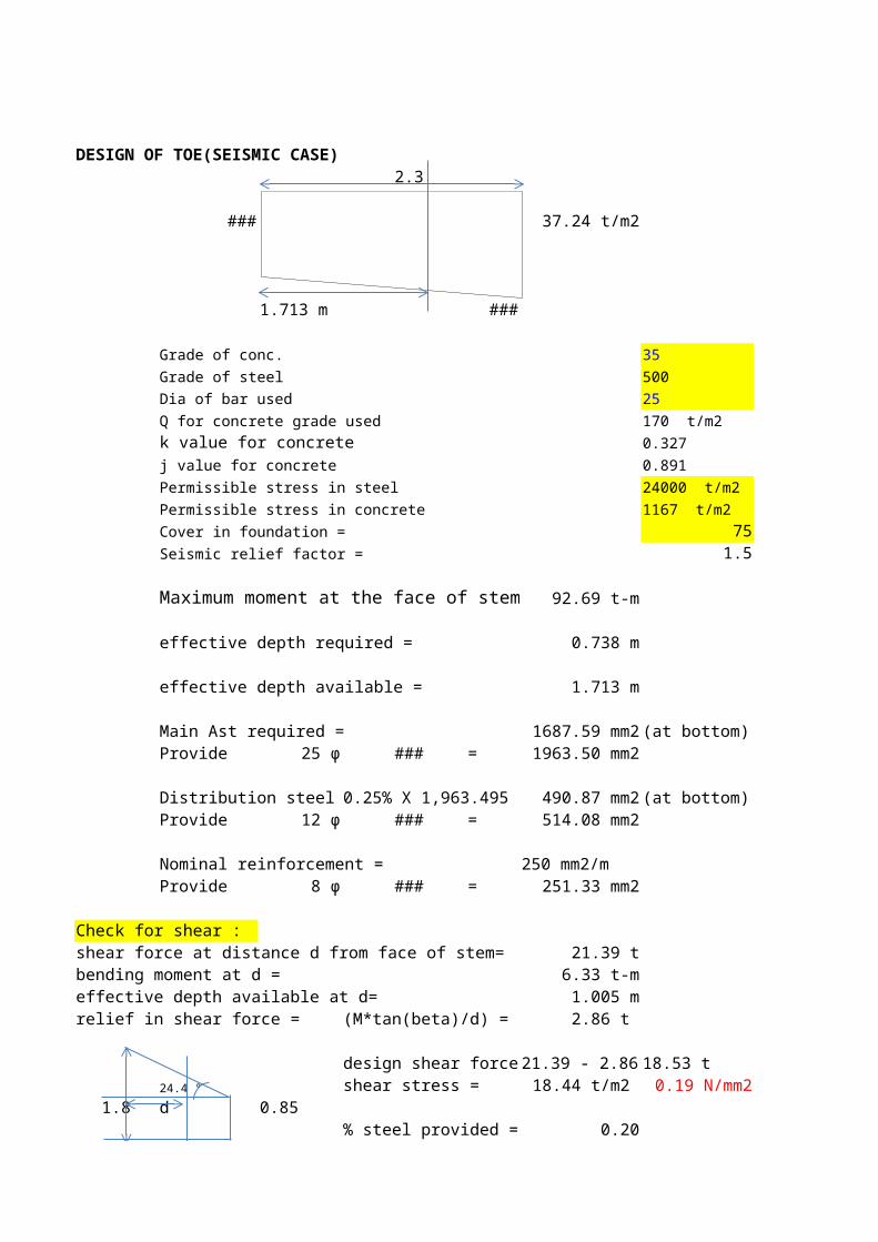
DESIGN OF TOE(SEISMIC CASE)2.3
30.65 t/m2 37.24 t/m2
1.713 m 35.6 t/m2
Grade of conc. 35
Grade of steel 500
Dia of bar used 25
Q for concrete grade used 170 t/m2
k value for concrete 0.327
j value for concrete 0.891
Permissible stress in steel 24000 t/m2
Permissible stress in concrete 1167 t/m2
Cover in foundation = 75Seismic relief factor = 1.5
Maximum moment at the face of stem = 92.69 t-m
effective depth required = 0.738 m
effective depth available = 1.713 m
Main Ast required = 1687.59 mm2 (at bottom)Provide 25 φ @ 250 c/c = 1963.50 mm2
Distribution steel = 0.25% X 1,963.495 = 490.87 mm2 (at bottom)Provide 12 φ @ 220 c/c = 514.08 mm2
Nominal reinforcement = 250 mm2/mProvide 8 φ @ 200 c/c = 251.33 mm2
Check for shear :shear force at distance d from face of stem= 21.39 tbending moment at d = 6.33 t-meffective depth available at d= 1.005 mrelief in shear force = (M*tan(beta)/d) = 2.86 t
design shear force= 21.39 - 2.86 = 18.53 t 24.4 ° shear stress = 18.44 t/m2 0.19 N/mm2 (τv)
1.8 d 0.85% steel provided = 0.20
2.3 τc = 0.22 N/mm2 > 0.19 N/mm2
Hence OK
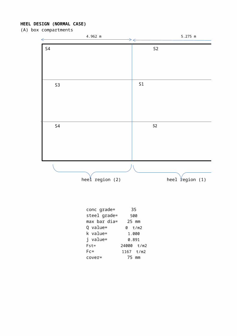
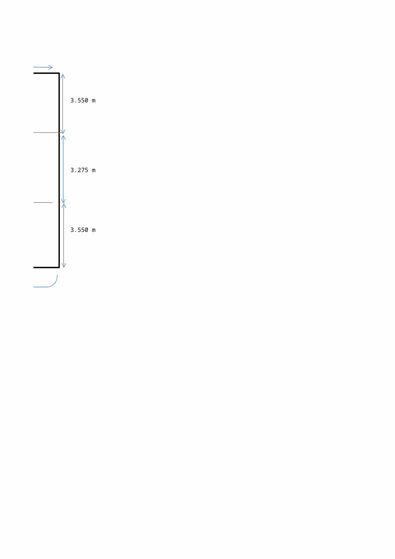
HEEL DESIGN (NORMAL CASE)(A) box compartments
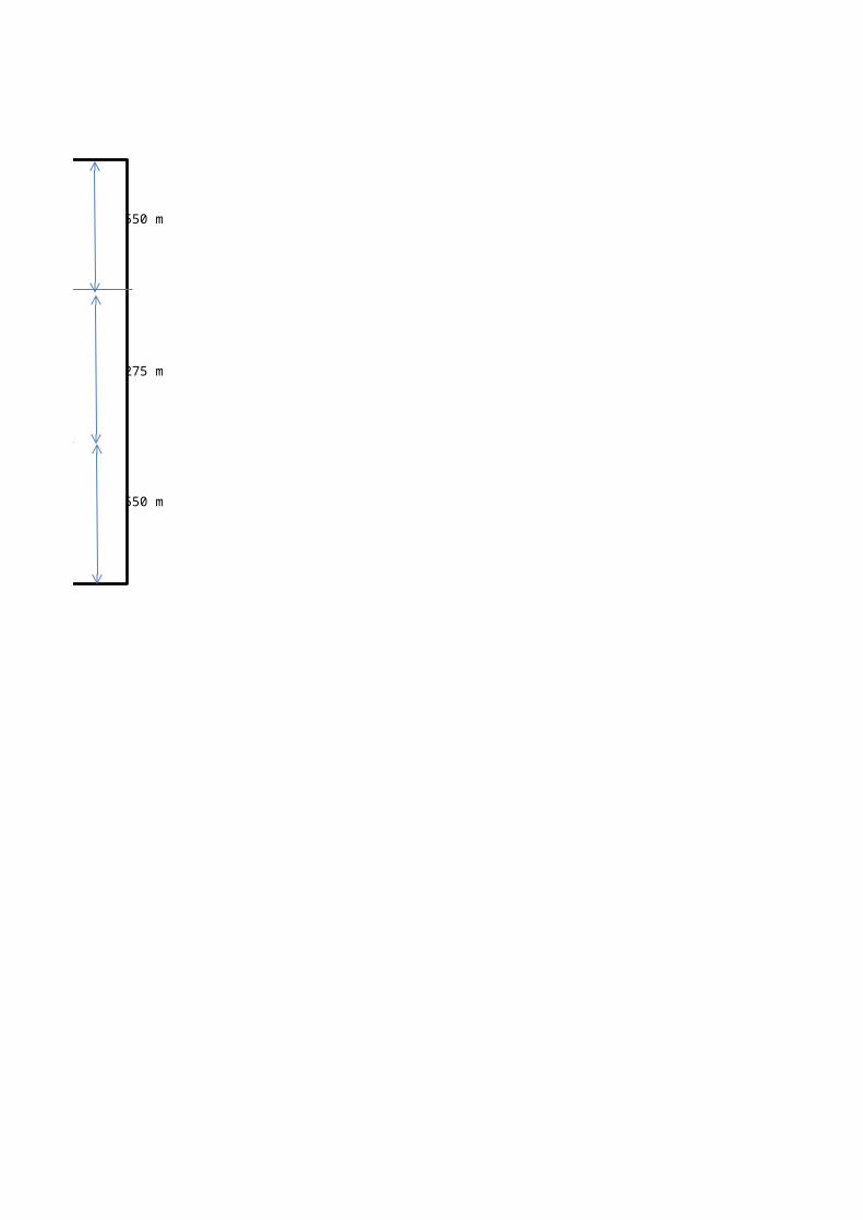
4.962 m 5.275 m
3.550 m
3.275 m
3.550 m
heel region (2) heel region (1)
conc grade= 35steel grade= 500
max bar dia= 25 mmQ value= 0 t/m2
k value= 1.000
j value= 0.891
Fst= 24000 t/m2
Fc= 1167 t/m2
cover= 75 mm
S4 S2
S3 S1
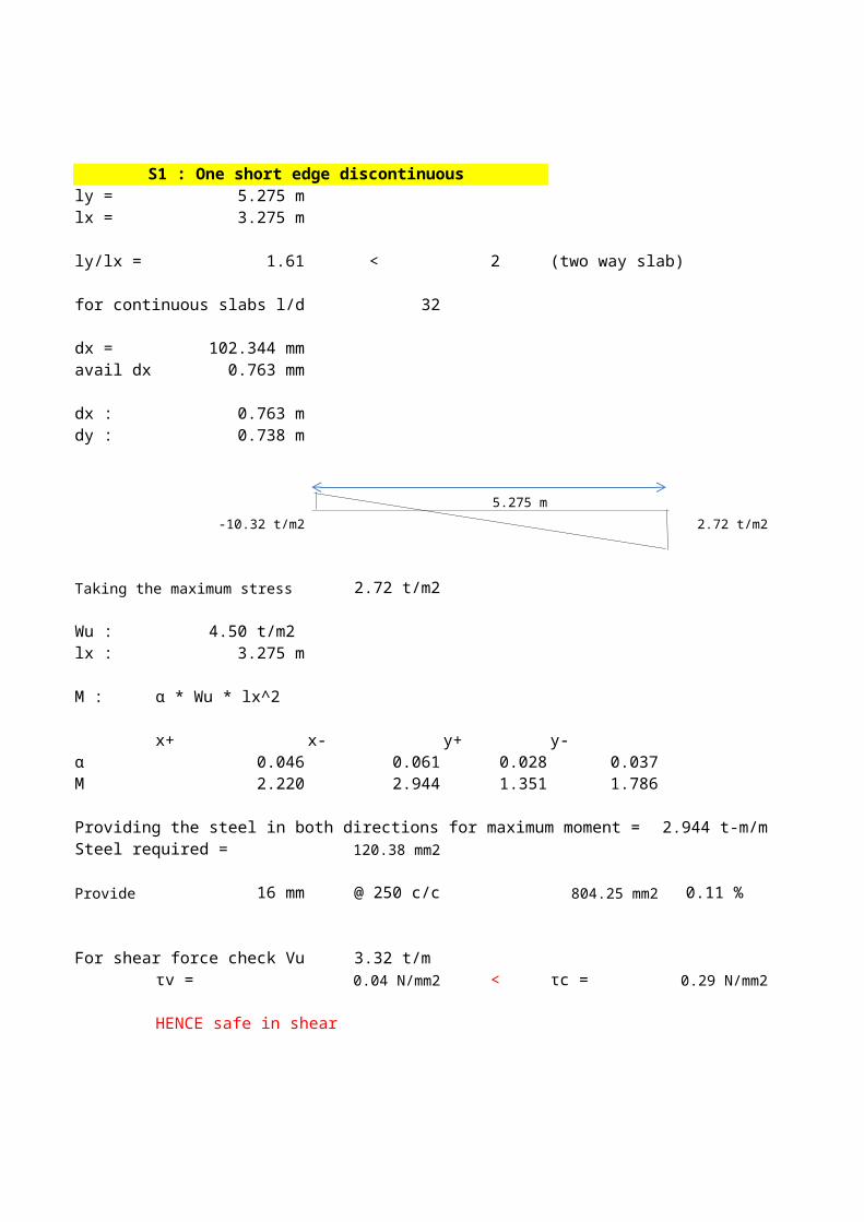
S4

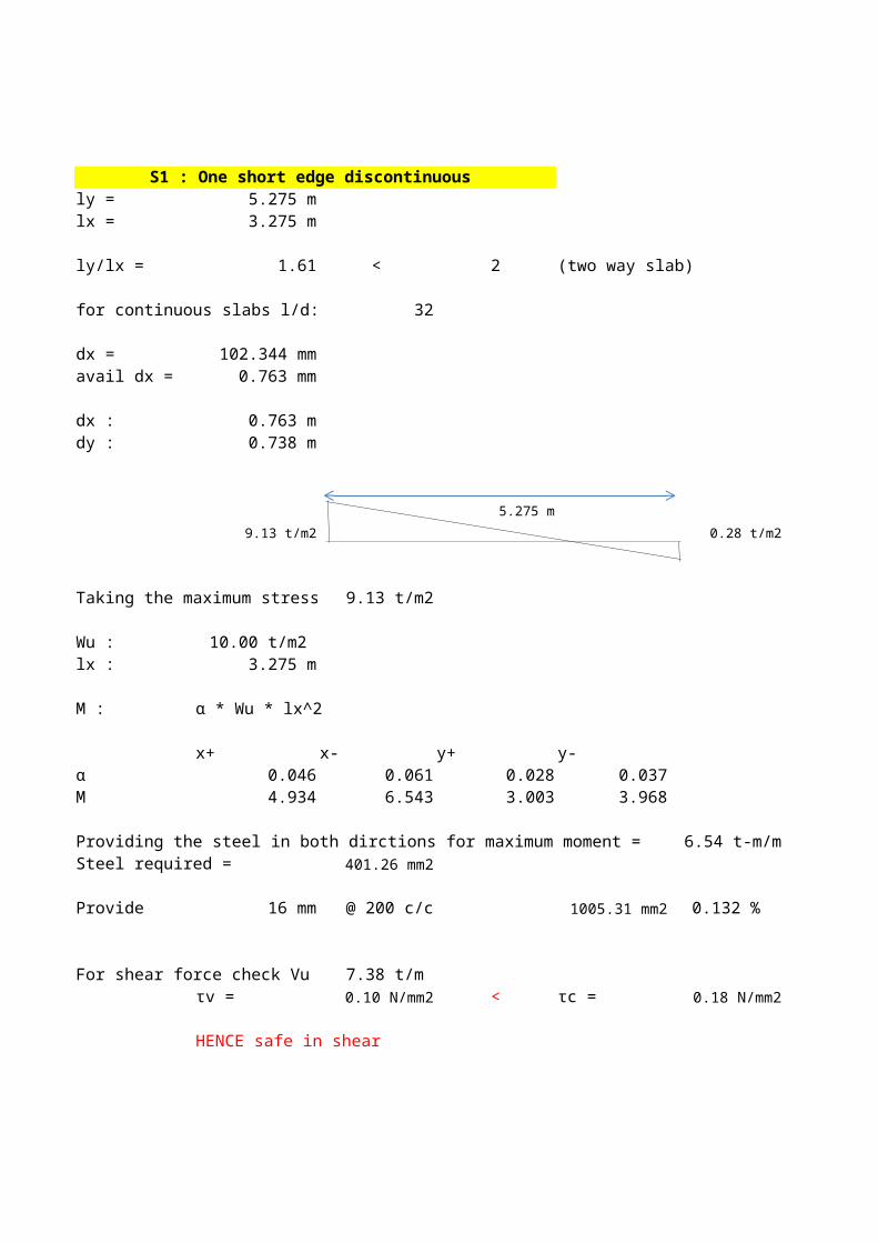
S1 : One short edge discontinuous ly = 5.275 mlx = 3.275 m
ly/lx = 1.61 < 2 (two way slab)
for continuous slabs l/d: 32
dx = 102.344 mmavail dx = 0.763 mm
dx : 0.763 mdy : 0.738 m
5.275 m
9.13 t/m2 0.28 t/m2
Taking the maximum stress 9.13 t/m2
Wu : 10.00 t/m2 lx : 3.275 m
M : α * Wu * lx^2
x+ x- y+ y-α 0.046 0.061 0.028 0.037M 4.934 6.543 3.003 3.968
Providing the steel in both dirctions for maximum moment = 6.54 t-m/mSteel required = 401.26 mm2
Provide 16 mm @ 200 c/c 1005.31 mm2 0.132 %
For shear force check Vu = 7.37 t/m τv = 0.10 N/mm2 < τc = 0.18 N/mm2
HENCE safe in shear

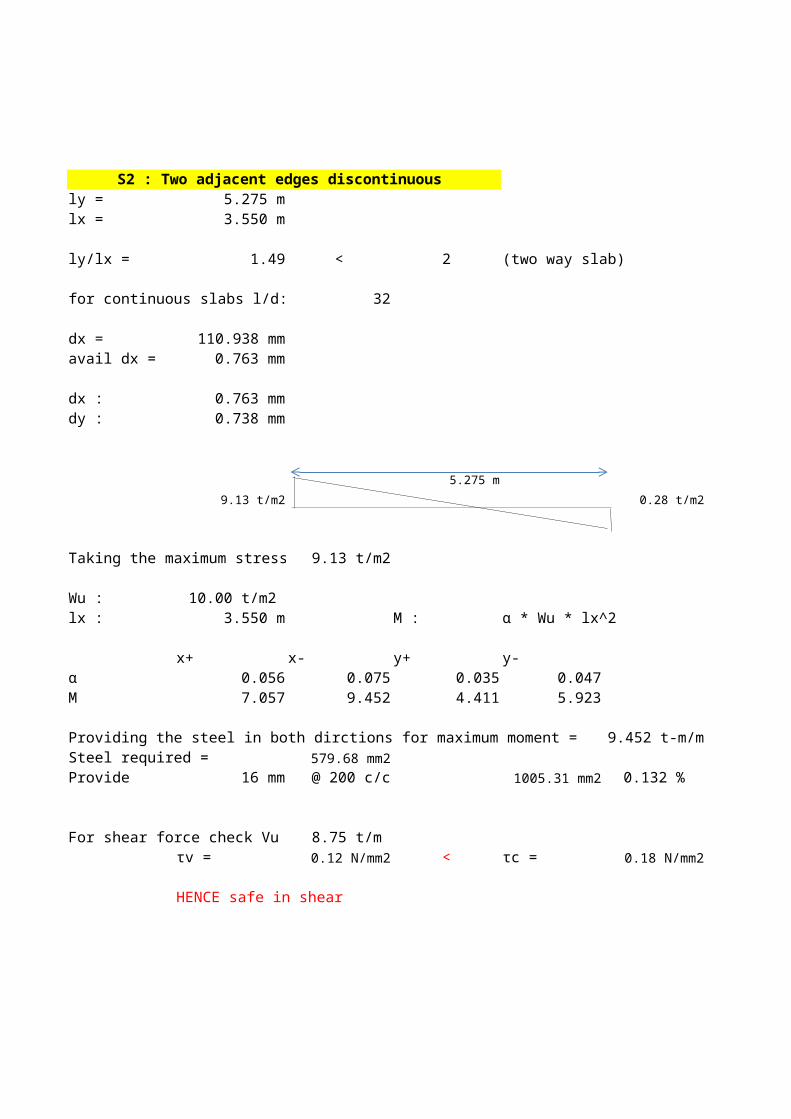
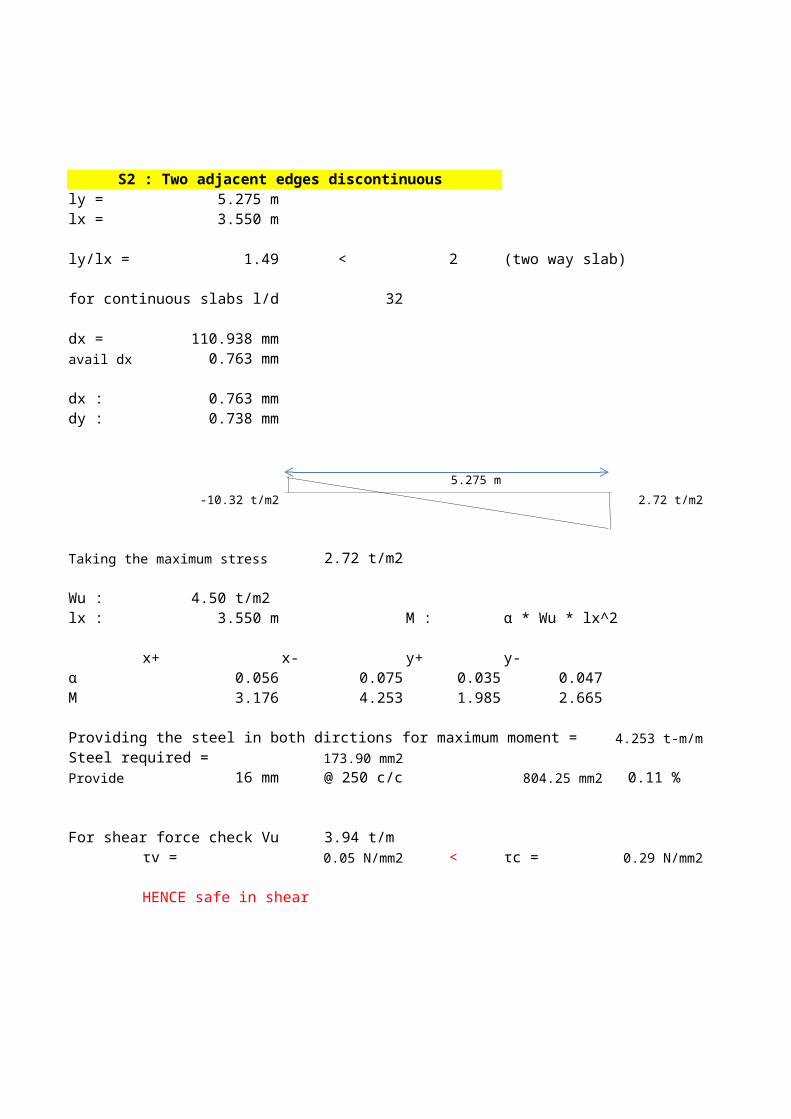
S2 : Two adjacent edges discontinuous ly = 5.275 mlx = 3.550 m
ly/lx = 1.49 < 2 (two way slab)
for continuous slabs l/d: 32
dx = 110.937 mmavail dx = 0.763 mm
dx : 0.763 mmdy : 0.738 mm
5.275 m
9.13 t/m2 0.28 t/m2
Taking the maximum stress 9.13 t/m2
Wu : 10.00 t/m2 lx : 3.550 m M : α * Wu * lx^2
x+ x- y+ y-α 0.056 0.075 0.035 0.047M 7.057 9.452 4.411 5.923
Providing the steel in both dirctions for maximum moment = 9.452 t-m/mSteel required = 579.68 mm2Provide 16 mm @ 200 c/c 1005.31 mm2 0.132 %
For shear force check Vu = 8.75 t/m τv = 0.12 N/mm2 < τc = 0.18 N/mm2
HENCE safe in shear

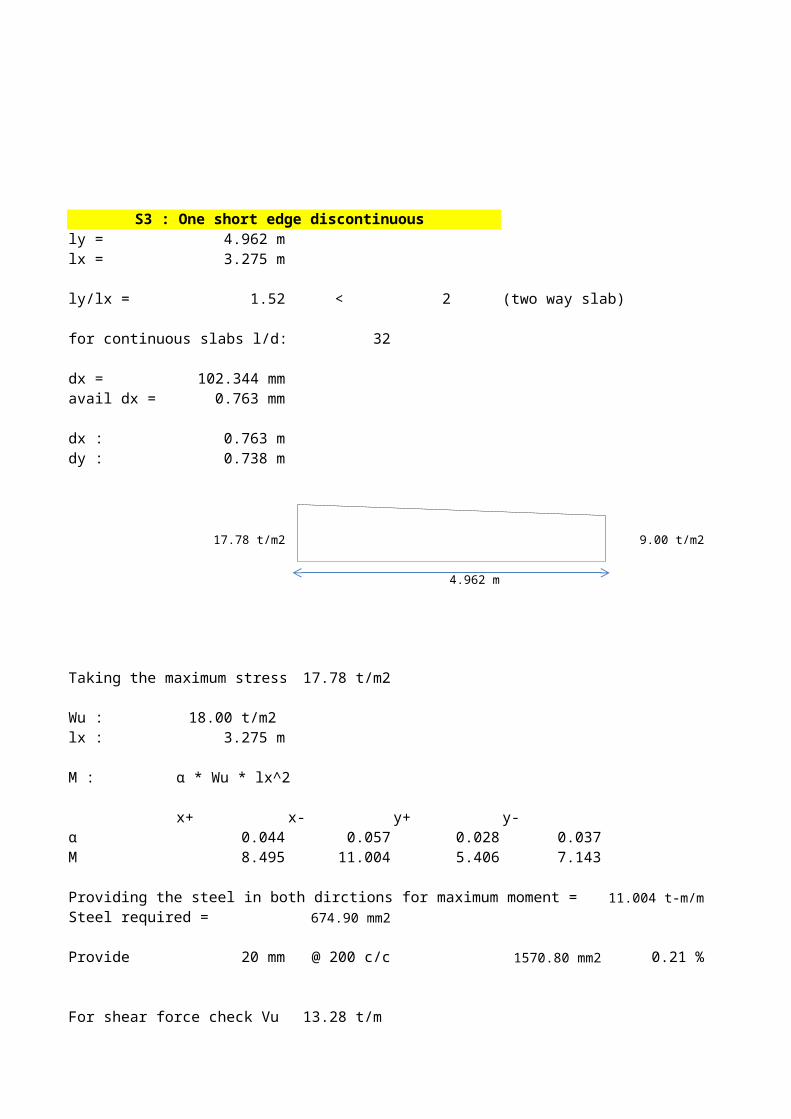
S3 : One short edge discontinuous ly = 4.962 mlx = 3.275 m
ly/lx = 1.52 < 2 (two way slab)
for continuous slabs l/d: 32
dx = 102.344 mmavail dx = 0.763 mm
dx : 0.763 mdy : 0.738 m
17.78 t/m2 9.00 t/m2
4.962 m
Taking the maximum stress 17.78 t/m2
Wu : 18.00 t/m2 lx : 3.275 m
M : α * Wu * lx^2
x+ x- y+ y-α 0.044 0.057 0.028 0.037M 8.495 11.004 5.406 7.143
Providing the steel in both dirctions for maximum moment = 11.004 t-m/mSteel required = 674.90 mm2
Provide 20 mm @ 200 c/c 1570.80 mm2 0.21 %
For shear force check Vu = 13.27 t/m
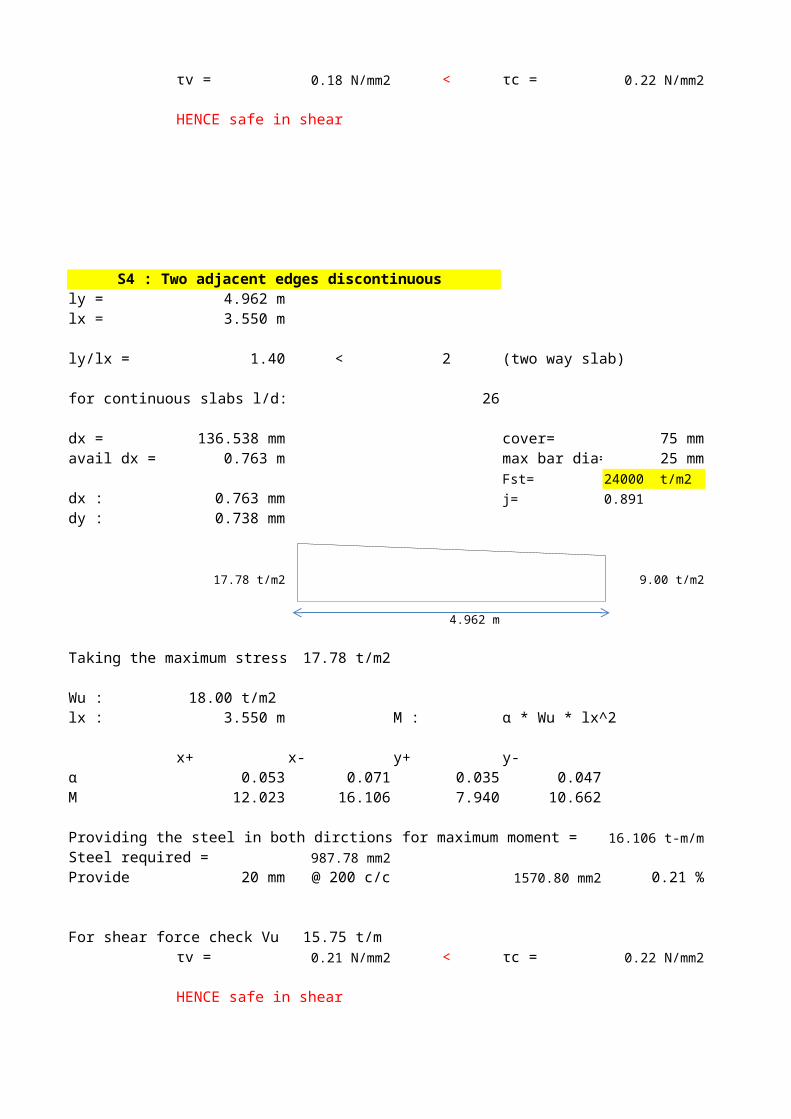
τv = 0.18 N/mm2 < τc = 0.22 N/mm2
HENCE safe in shear
S4 : Two adjacent edges discontinuous ly = 4.962 mlx = 3.550 m
ly/lx = 1.40 < 2 (two way slab)
for continuous slabs l/d: 26
dx = 136.538 mm cover= 75 mmavail dx = 0.763 m max bar dia= 25 mm
Fst= 24000 t/m2
dx : 0.763 mm j= 0.891
dy : 0.738 mm
17.78 t/m2 9.00 t/m2
4.962 m
Taking the maximum stress 17.78 t/m2
Wu : 18.00 t/m2 lx : 3.550 m M : α * Wu * lx^2
x+ x- y+ y-α 0.053 0.071 0.035 0.047M 12.023 16.106 7.940 10.662
Providing the steel in both dirctions for maximum moment = 16.106 t-m/mSteel required = 987.78 mm2Provide 20 mm @ 200 c/c 1570.80 mm2 0.21 %
For shear force check Vu = 15.75 t/m τv = 0.21 N/mm2 < τc = 0.22 N/mm2
HENCE safe in shear

HEEL DESIGN (NORMAL CASE)(A) box compartments
4.962 m 5.275 m
3.550 m
3.275 m
3.550 m
heel region (2) heel region (1)
conc grade= 35steel grade= 500
max bar dia= 25 mmQ value= 0 t/m2
k value= 1.000
j value= 0.891
Fst= 24000 t/m2
Fc= 1167 t/m2
cover= 75 mmseismic factor= 1.5
S4 S2
S3 S1
S4
S1 : One short edge discontinuous ly = 5.275 mlx = 3.275 m
ly/lx = 1.61 < 2 (two way slab)
for continuous slabs l/d: 32
dx = 102.344 mmavail dx = 0.763 mm
dx : 0.763 mdy : 0.738 m
5.275 m
-10.32 t/m2 2.72 t/m2
Taking the maximum stress 2.72 t/m2
Wu : 4.50 t/m2 lx : 3.275 m
M : α * Wu * lx^2
x+ x- y+ y-α 0.046 0.061 0.028 0.037M 2.220 2.944 1.351 1.786
Providing the steel in both directions for maximum moment = 2.944 t-m/mSteel required = 120.38 mm2
Provide 16 mm @ 250 c/c 804.25 mm2 0.11 %
For shear force check Vu = 3.32 t/m τv = 0.04 N/mm2 < τc = 0.29 N/mm2
HENCE safe in shear
S2 : Two adjacent edges discontinuous ly = 5.275 mlx = 3.550 m
ly/lx = 1.49 < 2 (two way slab)
for continuous slabs l/d: 32
dx = 110.937 mmavail dx = 0.763 mm
dx : 0.763 mmdy : 0.738 mm
5.275 m
-10.32 t/m2 2.72 t/m2
Taking the maximum stress 2.72 t/m2
Wu : 4.50 t/m2 lx : 3.550 m M : α * Wu * lx^2
x+ x- y+ y-α 0.056 0.075 0.035 0.047M 3.176 4.253 1.985 2.665
Providing the steel in both dirctions for maximum moment = 4.253 t-m/mSteel required = 173.90 mm2Provide 16 mm @ 250 c/c 804.25 mm2 0.11 %
For shear force check Vu = 3.94 t/m τv = 0.05 N/mm2 < τc = 0.29 N/mm2
HENCE safe in shear
S3 : One short edge discontinuous ly = 4.962 mlx = 3.275 m
ly/lx = 1.52 < 2 (two way slab)
for continuous slabs l/d: 32
dx = 102.344 mmavail dx = 0.763 mm
dx : 0.763 mdy : 0.738 m
23.37 t/m2 10.45 t/m2
4.962 m
Taking the maximum stress 23.37 t/m2
Wu : 36.00 t/m2 lx : 3.275 m
M : α * Wu * lx^2
x+ x- y+ y-α 0.044 0.057 0.028 0.037M 16.989 22.009 10.811 14.287
Providing the steel in both dirctions for maximum moment = 22.009 t-m/mSteel required = 899.87 mm2
Provide 25 mm @ 250 c/c 1963.50 mm2 0.26 %
For shear force check Vu = 26.55 t/m
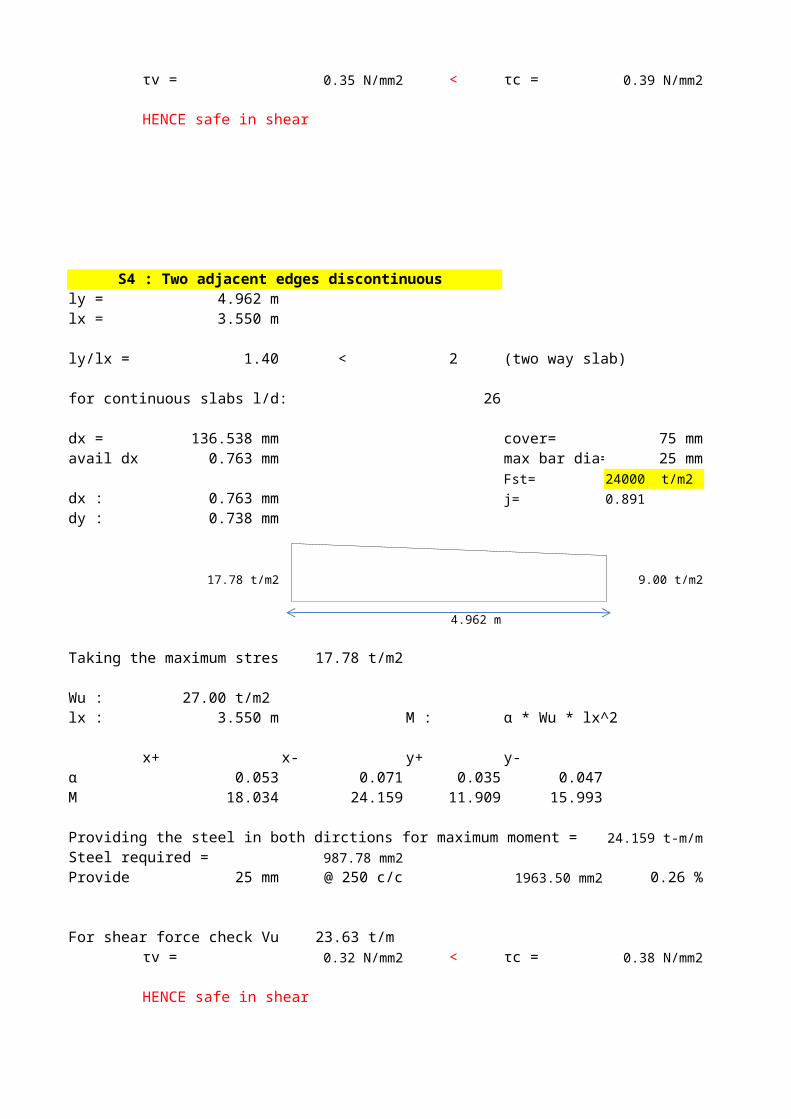
τv = 0.35 N/mm2 < τc = 0.39 N/mm2
HENCE safe in shear
S4 : Two adjacent edges discontinuous ly = 4.962 mlx = 3.550 m
ly/lx = 1.40 < 2 (two way slab)
for continuous slabs l/d: 26
dx = 136.538 mm cover= 75 mmavail dx = 0.763 mm max bar dia= 25 mm
Fst= 24000 t/m2
dx : 0.763 mm j= 0.891
dy : 0.738 mm
17.78 t/m2 9.00 t/m2
4.962 m
Taking the maximum stress 17.78 t/m2
Wu : 27.00 t/m2 lx : 3.550 m M : α * Wu * lx^2
x+ x- y+ y-α 0.053 0.071 0.035 0.047M 18.034 24.159 11.909 15.993
Providing the steel in both dirctions for maximum moment = 24.159 t-m/mSteel required = 987.78 mm2Provide 25 mm @ 250 c/c 1963.50 mm2 0.26 %
For shear force check Vu = 23.62 t/m τv = 0.31 N/mm2 < τc = 0.38 N/mm2
HENCE safe in shear
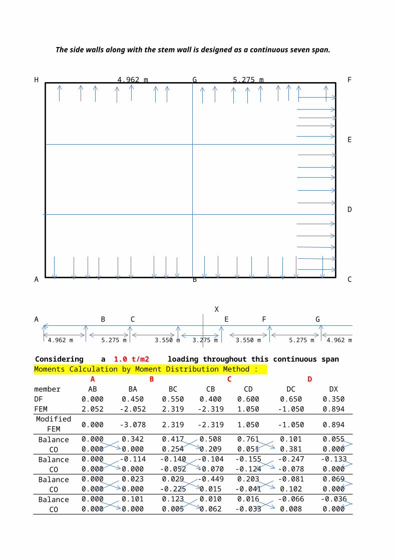
The side walls along with the stem wall is designed as a continuous seven span.
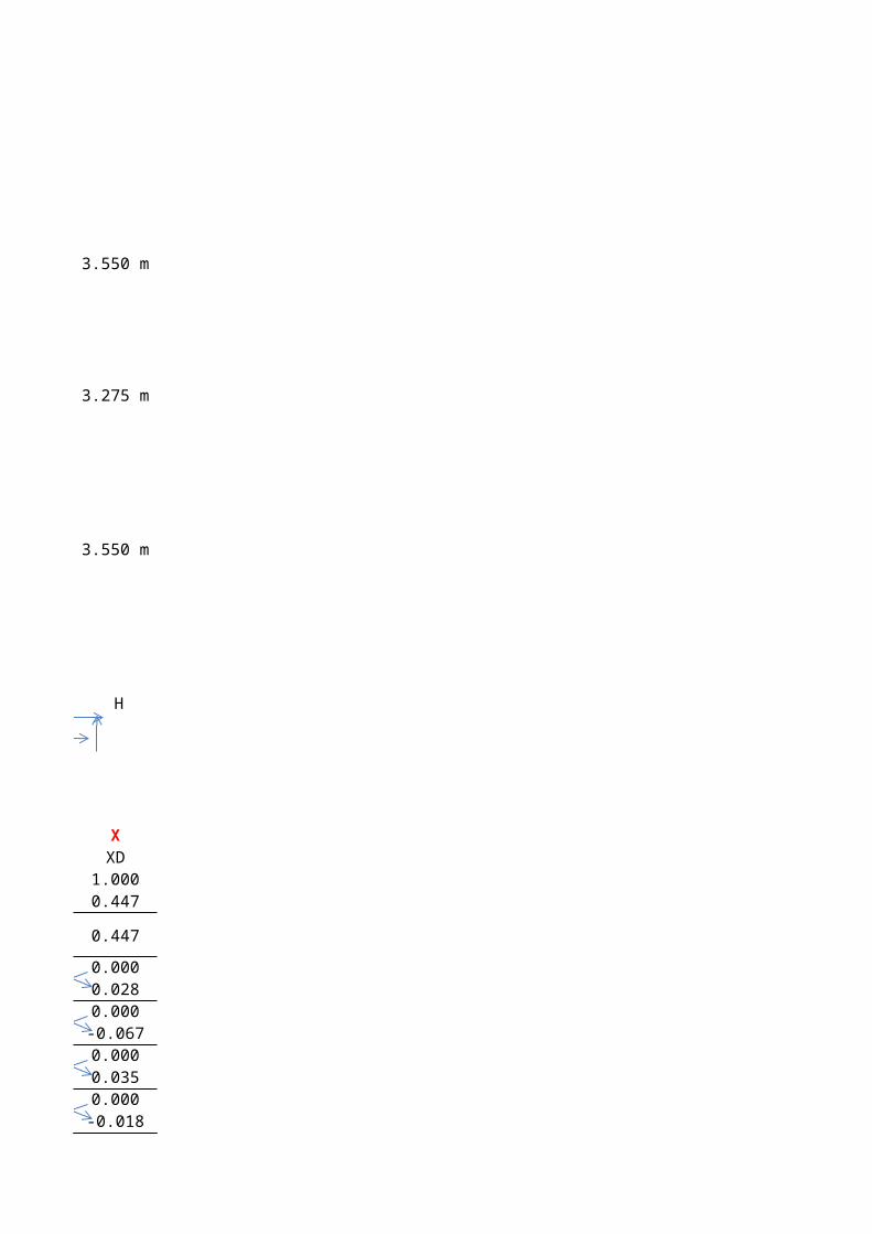
H 4.962 m G 5.275 m F
3.550 m
E
3.275 m
D
3.550 m
A B C
XA B C D E F G H
4.962 m 5.275 m 3.550 m 3.275 m 3.550 m 5.275 m 4.962 m
Considering a 1.0 t/m2 loading throughout this continuous spanMoments Calculation by Moment Distribution Method :
A B C D Xmember AB BA BC CB CD DC DX XDDF 0.000 0.450 0.550 0.400 0.600 0.650 0.350 1.000FEM 2.052 -2.052 2.319 -2.319 1.050 -1.050 0.894 0.447
0.000 -3.078 2.319 -2.319 1.050 -1.050 0.894 0.447
Balance 0.000 0.342 0.417 0.508 0.761 0.101 0.055 0.000CO 0.000 0.000 0.254 0.209 0.051 0.381 0.000 0.028
Balance 0.000 -0.114 -0.140 -0.104 -0.155 -0.247 -0.133 0.000CO 0.000 0.000 -0.052 -0.070 -0.124 -0.078 0.000 -0.067
Balance 0.000 0.023 0.029 -0.449 0.203 -0.081 0.069 0.000CO 0.000 0.000 -0.225 0.015 -0.041 0.102 0.000 0.035
Balance 0.000 0.101 0.123 0.010 0.016 -0.066 -0.036 0.000CO 0.000 0.000 0.005 0.062 -0.033 0.008 0.000 -0.018
Modified FEM
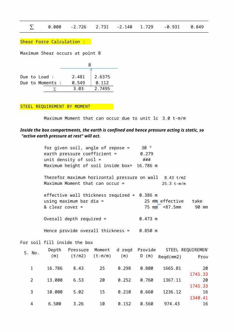
∑ 0.000 -2.726 2.730 -2.140 1.729 -0.931 0.849 0.425
Shear Force Calculation :
Maximum Shear occurs at point B
B
Due to Load : 2.481 2.6375Due to Moments : 0.549 0.112
∑ 3.03 2.7495
STEEL REQUIREMENT BY MOMENT
Maximum Moment that can occur due to unit load= 3.0 t-m/m
Inside the box compartments, the earth is confined and hence pressure acting is static, so "active earth pressure at rest" will act.
for given soil, angle of repose = 30 °earth pressure coefficient = 0.279unit density of soil = 1.80 t/m3Maximum height of soil inside box= 16.786 m
Therefor maximum horizontal pressure on wall = 8.43 t/m2Maximum Moment that can occur = 25.3 t-m/m
effective wall thickness required = 0.386 musing maximum bar dia = 25 mm take& clear cover = 75 mm 90 mm
Overall depth required = 0.473 m
Hence provide overall thickness = 0.850 m
For soil fill inside the box
S. No. Depth (m)STEEL REQUIREMENT(mm2)
Reqd(mm2) Provide
1 16.786 8.43 25 0.298 0.800 1665.81 20 1801745.33 0.22 %
2 13.000 6.53 20 0.252 0.760 1367.11 20 1801745.33 0.23 %
3 10.000 5.02 15 0.210 0.660 1236.12 16 1501340.41 0.20 %
4 6.500 3.26 10 0.152 0.560 974.43 16 200
effective =87.5mm
Pressure (t/m2)
Moment (t-m/m)
d reqd (m)
Provide D (m)
1005.31 0.18 %5 3.000 1.51 5 0.076 0.450 587.16 16 200
1005.31 0.22 %
Therefore wall overall thickness can vary from 0.80 m at bottom to0.45 m at top
STEEL REQUIREMENT BY SHEAR
Maximum Shear that can occur due to unit load= 3.03 t/m
Inside the box compartments, the earth is confined and hence pressure acting is static, so "active earth pressure at rest" will act.
for given soil, angle of repose = 30 °earth pressure coefficient = 0.279unit density of soil = 1.80 t/m3support thickness = 0.30 m
For soil fill inside the box
S. No. Depth (m) Vcr (t/m) τc (N/mm2)
1 16.786 8.43 18 0.800 0.219 0.221
2 13.000 6.53 14 0.760 0.179 0.224
3 10.000 5.02 10 0.660 0.158 0.215
4 6.500 3.26 7 0.560 0.121 0.227
5 3.000 1.51 3 0.450 0.070 0.246
At every section τv < τc , hence nominal shear shear reinforcement will doProvide 2 legged shear stirrup :
bar dia : 10 φ Asv = 78.5 mm2spacing: @ 200 c/c
Pressure (t/m2)
d provided
(m)τv
(N/mm2)
Design of Partition wall
This member is designed as a tension member with tensile force equal to the maximum reaction acting at the juncture of partition wall and the side walls
Maximum reaction force = 3.030 t/m + 2.750 t/m per 1.00 t/m2 load = 5.780 t/m
Permissible stress in steel 24000 t/m2
S. No. Ast provided
mm2
1 16.786 8.43 48.72 2030.03 1015.02 12 90 1256.637
2 13.000 6.53 37.73 1572.17 786.08 12 90 1256.637
3 10.000 5.02 29.02 1209.36 604.68 12 150 753.9822
4 6.500 3.26 18.87 786.08 393.04 12 150 753.9822
5 3.000 1.51 8.71 362.81 181.40 12 150 753.98223
Design of END wall
thickness of end wall = 0.300 m
Minimumreinforcement provided = 0.2% X bd= 600.00 mm2
Provide 12 150 753.98 mm2
Depth (m)
Pressure (t/m2)
Tension T(t/m)
Reqd Ast (mm2/m)
On each face (mm2/m)
bar dia (mm)
Spacing (mm)
In the end wall there is earth pressure acting from both sides hence net pressure is effectively zero. Thus minimum reinforcement would suffice.
Design Of COUNTERFORT WALLSINNER COUNTERFORTS (T-BEAMS)
influence zone for the counterfort walls= 3.412 m
(this is the width from which each counterfort receives the eatrh pressure)
unit weight of soil = 1.80 t/m3 Fst = 24000 t/m2earth pressure coeffiecnt = 0.279 j = 0.891
surcharge height = 1.20 mmaximum soil height = 16.786 m
pressure due to soil at specified depth = 0.502 X H (t/m2) (varying)pressure due to surcharge at specified depth = 0.603 t/m2 (constant)
pressure diagram will be somewhat like this
0.603 t/m2 2.06 t/m2
X 3.4125 = 16.786 m
9.033 t/m2 30.83 t/m2
D = 9.662 m max bar dia = 32 φd = 9.596 m clear cover = 50 mmb= 0.300 m
S. No. Depth (m)STEEL REQUIREMENT(mm2)
Provide φ nos
1 16.786 30.83 1641 7999.044 32 9.00
2 13.000 24.34 1337 6513.915 32 7.00
3 10.000 19.20 1095 5337.109 32 6.00
4 6.500 13.20 813 3964.169 32 4.00
5 3.000 7.20 532 2591.229 32 3.00
Pressure at this depth
(t/m2)
Moment (t-m/m) Reqd
(mm2)

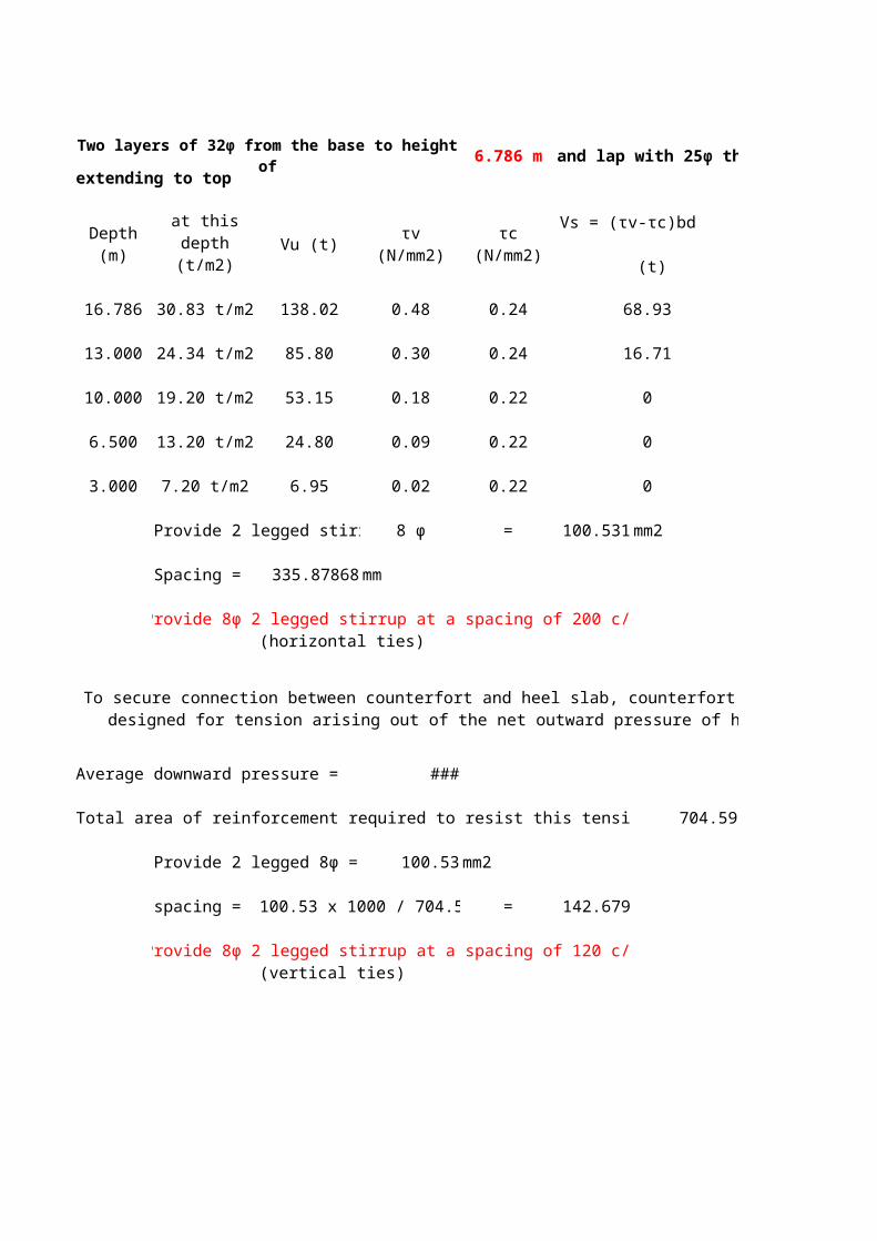
Two layers of 32φ from the base to height of 6.786 m and lap with 25φ therafter extending to top
Vu (t) τv (N/mm2)
16.786 30.83 t/m2 138.02 0.48 0.24 68.93
13.000 24.34 t/m2 85.80 0.30 0.24 16.71
10.000 19.20 t/m2 53.15 0.18 0.22 0
6.500 13.20 t/m2 24.80 0.09 0.22 0
3.000 7.20 t/m2 6.95 0.02 0.22 0
Provide 2 legged stirrup 8 φ = 100.531 mm2
Spacing = 335.87868 mm
Provide 8φ 2 legged stirrup at a spacing of 200 c/c(horizontal ties)
Average downward pressure = 16.91 t/m2
Total area of reinforcement required to resist this tension = 704.59 mm2/m
Provide 2 legged 8φ = 100.53 mm2
spacing = 100.53 x 1000 / 704.59 = 142.679
Provide 8φ 2 legged stirrup at a spacing of 120 c/c(vertical ties)
Depth (m)
Pressure at this depth
(t/m2)
τc (N/mm2)
Vs = (τv-τc)bd (t)
To secure connection between counterfort and heel slab, counterfort needs to be designed for tension arising out of the net outward pressure of heel slab.
OUTER COUNTERFORTS (L BEAMS)influence zone for the counterfort walls= 1.775 m
(this is the width from which each counterfort receives the eatrh pressure)
unit weight of soil = 1.80 t/m3 Fst = 24000 t/m2earth pressure coeffiecnt = 0.279 j = 0.891
surcharge height = 1.20 mmaximum soil height = 16.786 m
pressure due to soil at specified depth = 0.502 X H (t/m2) (varying)pressure due to surcharge at specified depth = 0.603 t/m2 (constant)
pressure diagram will be somewhat like this
0.603 t/m2 1.07 t/m2
X 1.775 = 16.786 m
9.033 t/m2 16.04 t/m2
D = 9.662 m max bar dia = 32 φd = 9.596 m clear cover = 50 mmb= 0.850 m
S. No. Depth (m)STEEL REQUIREMENT(mm2)
Provide φ nos
1 16.786 16.04 854 4160.876 32 5.00
2 13.000 12.66 695 3388.114 32 5.00
3 10.000 9.99 570 2775.782 32 3.00
4 6.500 6.87 423 2061.395 32 3.00
Pressure at this depth
(t/m2)
Moment (t-m/m) Reqd
(mm2)
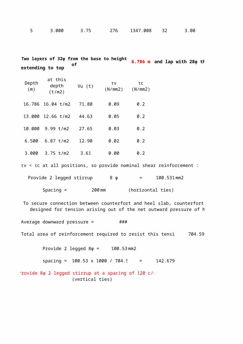
5 3.000 3.75 276 1347.008 32 3.00
Two layers of 32φ from the base to height of 6.786 m and lap with 28φ therafter extending to top
Vu (t) τv (N/mm2)
16.786 16.04 t/m2 71.80 0.09 0.2
13.000 12.66 t/m2 44.63 0.05 0.2
10.000 9.99 t/m2 27.65 0.03 0.2
6.500 6.87 t/m2 12.90 0.02 0.2
3.000 3.75 t/m2 3.61 0.00 0.2
τv < τc at all positions, so provide nominal shear reinforcement :
Provide 2 legged stirrup 8 φ = 100.531 mm2
Spacing = 200 mm (horizontal ties)
Average downward pressure = 16.91 t/m2
Total area of reinforcement required to resist this tension = 704.59 mm2/m
Provide 2 legged 8φ = 100.53 mm2
spacing = 100.53 x 1000 / 704.59 = 142.679
Provide 8φ 2 legged stirrup at a spacing of 120 c/c(vertical ties)
Depth (m)
Pressure at this depth
(t/m2)
τc (N/mm2)
To secure connection between counterfort and heel slab, counterfort needs to be designed for tension arising out of the net outward pressure of heel slab.

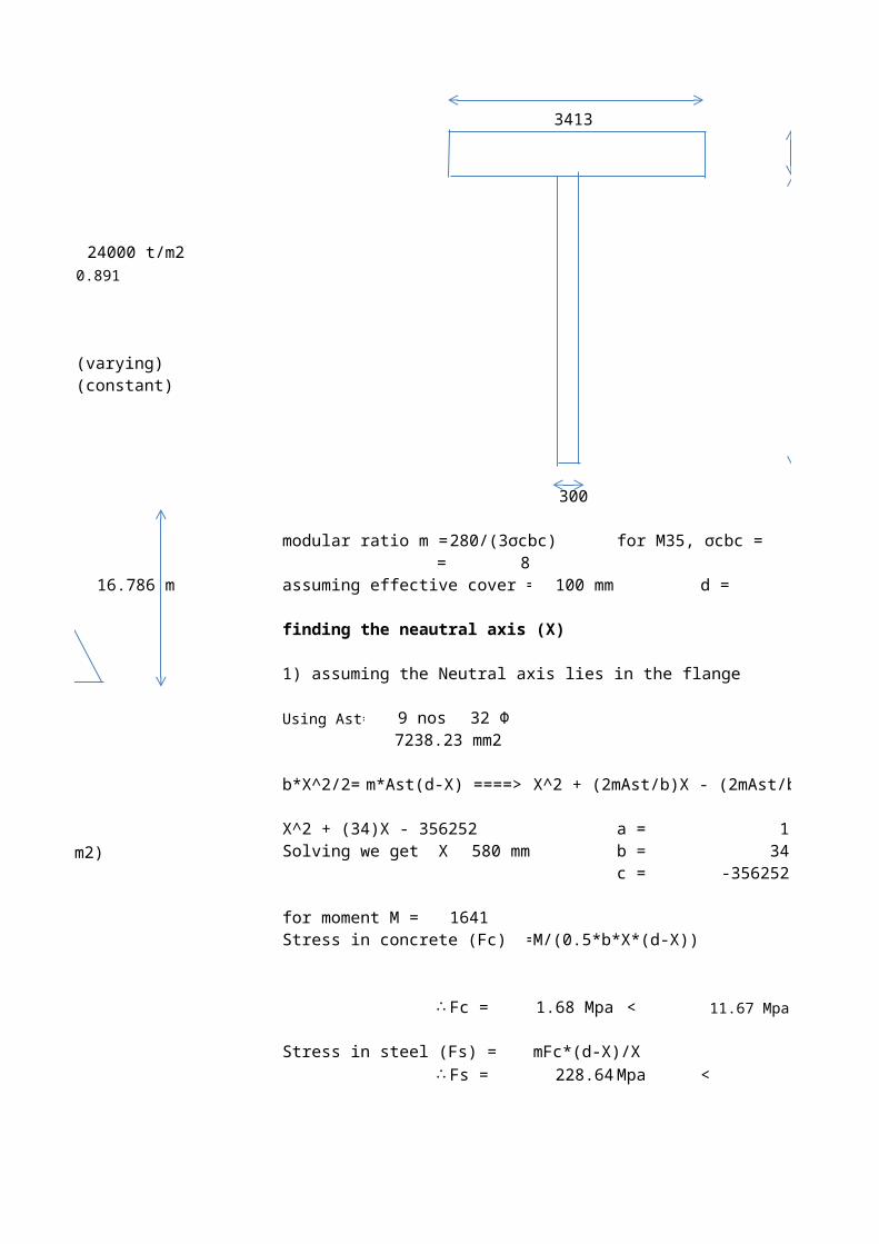
3413
850
9728
300
modular ratio m = 280/(3σcbc) for M35, σcbc = 11.67= 8
assuming effective cover = 100 mm d = 10478 mm
finding the neautral axis (X)
1) assuming the Neutral axis lies in the flange
Using Ast= 9 nos 32 Φ7238.23 mm2
b*X^2/2= m*Ast(d-X) ====> X^2 + (2mAst/b)X - (2mAst/b)d
X^2 + (34)X - 356252 a = 1Solving we get X = 580 mm b = 34
c = -356252
for moment M = 1641Stress in concrete (Fc) = M/(0.5*b*X*(d-X))
∴ Fc = 1.68 Mpa < 11.67 Mpa
Stress in steel (Fs) = mFc*(d-X)/X∴ Fs = 228.64 Mpa < 240 MPa
N34
coefficients of quadratic equation
L35
Assumption is correct
M44
Linear stress distribution
1775
850
9817
850
modular ratio m = 280/(3σcbc) for M35, σcbc = 11.67= 8
assuming effective cover = 100 mm d = 10567 mm
finding the neautral axis (X)
1) assuming the Neutral axis lies in the flange
Using Ast= 3 nos 32 Φ2412.74 mm2
b*X^2/2= m*Ast(d-X) ====> X^2 + (2mAst/b)X - (2mAst/b)d
X^2 + (22)X - 232474 a = 1Solving we get X = 471 mm b = 22
c = -232474
for moment M = 423Stress in concrete (Fc) = M/(0.5*b*X*(d-X))
∴ Fc = 1.00 Mpa < 11.67 Mpa
Stress in steel (Fs) = mFc*(d-X)/X∴ Fs = 171.66 Mpa < 240 MPa
N133
coefficients of quadratic equation
L134
Assumption is correct
M143
Linear stress distribution
Design of ROOF SLAB by Pigeud's curve
Thickness of slab = 0.30 mwearing course = 56.00 mm
B= span in transverse direction = 3.550 m (short)L= span in longitudinal direction = 5.275 m (long)
Maximum bending moment due to dead load =
weight of deck slab = 0.720 t/m2weight of wearing course = 0.123 t/m2
total weight = 0.843 t/m2along short span
K = short span/long span = 0.67 ===>> m1 = 0.047from Pigeud's curve
1/K = 1.49 ===>> m2 = 0.018along long span
poisson's ratio µ = 0.15 for reinforced concrete bridges
Total dead weight W = 15.79 t
moment along short span = (m1+ µ*m2)*W = 0.78 t-mmoment along long span = (m2+ µ*m1)*W = 0.40 t-m
Live load bending moment due to IRC Class AA tracked vehicle =
0.85
3.6
SIZE OF PANEL of deck slab= 3.550 m X 5.275 mimpact factor= 25 %
u= width of load spread along short span= 0.962 mv= width of load spread along long span= 3.712 m limited to 5.275 m
K= 0.67 using pigeud's curve=u/B= 0.271 m1= 0.12v/L= 0.704 m2= 0.048
ONE TRACK
load per track of AA= 35.00 t
total load per track including impact = 1.25*35 = 43.75 t
effective load on span= 43.75*3.712/3.712 = 43.75 t
moment along short span= (m1+µ*m2)*43.75 = 5.57 t-m
moment along long span= (m2+µ*m1)*43.75 = 2.89 t-m
Live load bending moment due to IRC Class AA wheeled vehicle =
Y
2.6375
4 1 2 3X 3.75 t 6.25 t 6.25 t 3.75 t X
2.6375 8 5 6 73.75 t 6.25 t 6.25 t 3.75 t
1.775 Y 1.775
The Class AA wheeled vehicle is placed as shown to produce the severest moments. The front axle is placed along the centre line with 6.25t wheel at centre of panel. Maximum moments in the short span and long span directions are computed for individual wheel loads taken in the order shown

B = 3.550 mL = 5.275 m
Bending Moment due to wheel 1 = 6.25 t
tyre contact dimensions= 300 X 150 mm
u= sqrt((0.3+2*0.056)^2+0.3^2)= 0.5097
v= sqrt((0.15+2*0.056)^2+0.3^2)= 0.3984
u/B = 0.144 v/L = 0.076 K = 0.70
m1 = 0.221 Total load allowing for 25 % impact = 7.813 tm2 = 0.190
Moment along short span = 1.950 t-mMoment along long span = 1.744 t-m
Bending Moment due to wheel 2 = 6.25 t
Y
X 6.25 t 6.25 t X
0.3 0.85 0.85 0.3Y
2.3
Intensity of loading = (6.25*1.25)/(0.5097*0.3984) = 38.47 t/m2
Consider the loaded area of 0.150 X 2.300
u = sqrt((2.3+2*0.056)^2+0.3^2) = 2.4306v = sqrt((0.15+2*0.056)^2+0.3^2) = 0.3983
u/B = 0.685 v/L = 0.076 K = 0.70
Here wheel load is placed unsymmetrical to YY axis. But Pigeuds Curves are derived for symmetrical loading. Hence we place an equal dummy load symmetrical about the YY axis and consider the whole loading area. Then we deduct the area beyond the actual loaded area. Half of the resulting value is taken as the moment due to actual loading.
m1 = 0.112m2 = 0.119
Moment along short span = 4.578 t-mMoment along long span = 4.788 t-m
Now consider the area beyond the actual loading = 1.7 X 0.15
u = sqrt((1.7+2*0.056)^2+0.3^2) = 1.8367v = sqrt((0.15+2*0.056)^2+0.3^2) = 0.3983
u/B = 0.517 v/L = 0.076 K = 0.70
m1 = 0.132m2 = 0.14
Moment along short span = 3.517 t-mMoment along long span = 3.674 t-m
Net moment along short span = 0.531 t-mNet moment along long span = 0.557 t-m
Bending Moment due to wheel 3 = 3.75 t
By similar procedure as for previous case, we getB.M along short span = 0.052 t-mB.M along long span = 0.121 t-m
Bending Moment due to wheel 4 = 3.75 t
By similar procedure as for previous case, we getB.M along short span = 0.520 t-mB.M along long span = 0.607 t-m
Bending Moment due to wheel 5 = 6.25 t
B.M along short span = 0.823 t-mB.M along long span = 0.195 t-m
Bending Moment due to wheel 6 = 6.25 t
In this case loading is eccentric w.r.t XX axis. By similar procedure as for previous case but with load area extended w.r.t. XX axis, we get

B.M along short span = 0.823 t-mB.M along long span = 0.195 t-m
Bending Moment due to wheel 7 = 3.75 t
By similar procedure as for previous case, we getB.M along short span = 0.486 t-mB.M along long span = 0.115 t-m
Bending Moment due to wheel 8 = 3.75 t
By similar procedure as for previous case, we getB.M along short span = 0.486 t-mB.M along long span = 0.115 t-m
total bending moment along short span = 5.671 t-m
total bending moment along long span = 3.649 t-m
To allow for continuity, the computed momnts are multiplied by a factor of 0.8
Design Bending Moment=along short span= 5.16 t-malong long span= 3.24 t-m
Grade of conc. 35
Grade of steel 500
Dia of bar used 16
Q for concrete grade used 170 t/m2
k value for concrete 0.327
j value for concrete 0.891
Permissible stress in steel 24000 t/m2
Permissible stress in concrete 1167 t/m2
cover 50 mm
effective depth required= 0.174 mprovided deff = 0.242 m OK
In this case loading is eccentric with respect to both XX and YY axes. A strict simulation would be very complicated and laborious. For A reasonable approximation, eccentricity w.r.t. only XX axis is considered and calculations made as for previous case.

main reinforcement required= 998 mm2So provide ϕ 16 @ 150 c/c 1340 mm2 OK
longitudinal reinforcement required = 625 mm2So provide ϕ 12 @ 150 c/c 754 mm2 OK

Design of Abutment Cap
Taking thickness equal to 225 mm for calculation of steel requirement.
Y
X
Along X direction
0.225 m
2.781 m
Steel reqd = 1% of cross section = 6257.25 mm2
steel on both top and bottom face = 1/2 of steel reqd= 3128.625 mm2
Provide ϕ 25 @ 150 c/c = 3272.492 mm2
Along Y direction
0.225 m
1.000 m
Steel reqd = 1% of cross section 2250 mm2
steel on both top and bottom face = 1/2 of steel red= 1125 mm2
Provide ϕ 12 @ 150 c/c = 1507.964 mm2==> 2 legged stirrup

DESIGN OF DIRTWALL
varies
Design values :
0.35 m 1.80 t/m2 3.036
2 1 0.279
1.525 t/m2 0.603 t/m2 0.350 m
Earth Pressure diagram
3.036 m
1)Earth Pressure due to surcharge equivalent to 1.2m of earthfill
= 0.603 t/m2
2)Earth Pressure due to backfill of earth =
= 1.525 t/m2
Bending moment at the base of dirtwall due to earth pressure (1)
= 2.777 t-m/m
Bending moment at the base of dirtwall due to earth pressure (1)
= 2.342 t-m/m
Total bending moment at the base of dirtwall = 5.120 t-m/mdue to earth pressure
Calculation of force and moment due to the effect of braking :(cosidering 40t bogie loading)
1.7 10t 10.85 10t
2.79m Dirt Wall3.036
1.750 2.79 3.036
Effective width = 7.576 m
Braking force, 0.2*20 = 4 t (Only two wheels can come on dirt wall at a time.)Braking force = 4 t (Impact factor can't be included with braking force)
Braking force per metre width = 0.53 t
Bending moment at the base of dirtwall due to effect of braking 2.24 t-m/m
g =
ka =
width of dirtwall =
height of dirtwall,h =
ka *g*1.2
ka *g*h
ka *g*1.2*h2/2
ka *g*h3/6
Max. wheel load is from 40t boggie load. So, considering this case only. Wheel Loads shown below are placed on dirt wall (not on RCC Solid Slab) along carriage-way. So, dispersion is taken directly at 45
degrees.

Therefore total bending moment at the base of the dirtwall 7.36 t-m/m
Basic Design Data:
Grade of conc. 35Grade of steel 500Dia of bar used 16Permissible stress in concrete 1167 t/m2Permissible stress in steel ###m , Modulur ratio 10 K value for concrete 0.327j value for concrete 0.891Q for concrete 170.08
Max. moment in dirtwall (t-m) 7.36
Effective depth required (mm) 208
Effective depth provided (mm) 292 SAFE
1178
Provide Vertical longitudinal reinforcement:
Use f16 @ 150 c/c
(On Approach Side face) = 1340 Thus OK
Min. Reinforcent in vertical direction (On outer face) = 525 For 1m lengthUse f16 @ 200 c/c
1005 Thus OK
Ast required (mm2)
Ast provided (mm2)
Therefore providing 20 f @ 130 c/c on the approach side and 12 f @ 200 c/c (Min. % reinforcement) on the outer side in the vertical direction . Also providing 12 f @ 200 c/c on both faces in the horizontal
direction .

DESIGN OF DIRTWALL I Normal Case with Live load
In the design of dirtwall the total height cosidered has been calculated taking into account a slope of 2.5% provided in the carriageway.
For Backfill Soil :a = 90.0 degree
0.35 b = 0.0 degree3.036 f = 30.0 degree
1 2 d = 20.0 degreeKah = 0.279
1.525 t/m2 0.603 t/m2 g = 1.8
Earth Pressure diagram
Height of dirtwall = 3.036 m
1 Earth Pressure due to surcharge equivalent to 1.2m of earthfill = 0.603
2 Earth Pressure due to backfill of earth = 1.525
Bending moment at the base of dirtwall due to earth pressure (1) = 2.78 t-m/mBending moment at the base of dirtwall due to earth pressure (2) = 2.95 t-m/m
Total bending moment at the base of dirtwall = 5.73 t-m/m
Calculation of force and moment due to the effect of braking :(cosidering 40t bogie loading)
1.710t 10t
3.04 2.79m
1.700 2.79 3.036
Effective width = 7.526 mBraking force, 0.2*20 = 4.0 tBraking force per metre width = 0.53 tBending moment at the base of dirtwall due to effect of braking = 1.61 t-m/m
Therefore total bending moment at the base of the dirtwall = 7.34 t-m/m
t/m3
t/m2
t/m2
II Seismic CaseIn the design of dirtwall the total height cosidered has been calculated taking into account a slope of 2.5% provided in the carriageway.
For Backfill Soil :a = 90.0 degree
0.30 b = 0.0 degree3.036 f = 33.0 degree
1 2 d = 22.0 degreeCah = 0.134
0.730 t/m2 0.288 t/m2 g = 1.8
Earth Pressure diagram
Height of dirtwall = 3.036 m
1 Earth Pressure due to surcharge equivalent to 1.2m of earthfill = 0.288
2 Earth Pressure due to backfill of earth = 0.7303 Horizondal force due to seismic = 0.231 t/m
Bending moment at the base of dirtwall due to earth pressure (1) = 1.76 t-m/mBending moment at the base of dirtwall due to earth pressure (2) = 1.41 t-m/mBending moment at the base of dirtwall due to seismic horizondal force (3) = 0.35 t-m/m
Total bending moment at the base of dirtwall = 3.52 t-m/mTherefore Normal case govern for the design
CALCULATION OF DESIGN PARAMETERS
Grade of concrete = M 35Grade of steel = Fe 500
Permissible stresses:
sst = 24480
sbc = 1190
Basic Design Parameters:
k = 0.327j = 0.891
Q = 173.41
Required effective depth =(7.34/173.41)^0.5 = 0.206 m
Depth provided = 0.35- 0.05 - (16/2000) = 0.292 mThus OK
Required Ast =7.34*10000/(24480*0.891*0.292) = 11.53
50% of additional reinforcement should be provided as per note of transport ministry 17.30
Provide 16 f @ 100 c/c at earth face = 20.11Thus OK
Min reinforcement = 0.06% of cross sectional area = 2.1
Dirt wall has been designed for normal case, wind case and seismic case. permisible stresses are increased by 33%/50% and hence it does not governs.
t/m3
t/m2
t/m2
t/m2
t/m2
t/m2
cm2/m
cm2/m
cm2/m
cm2/m
Provide 10 f @ 150 c/c outer face = 5.24Thus OK
Provide 10 f @ 150 c/c Horz both face 5.24
DESIGN OF ABUTMENT CAP
Assuming thickness of abutment cap = 225.0 mm
Width of abutment cap = 1420 mmThickness of abutment cap = 400 mmLength of abutment cap = 11379 mm
Area of steel required (min 1%) = 36355905
Quantity of steel to be provided at top = 18177953
Quantity of steel to be provided at bottom = 18177953
Top Face(a) Longitudnal steel
Quantity of steel to be provided in longitudnal direction ( 0.5*total steel at top ) = 9088976Assuming a clear cover of = 50.0 mm
Length of bar = 11279.0 mm
Area of steel required in longitudnal direction = 805.8
Provide 8 bar of 12 mm dia bar as longitudnal steel on top face of abutment cap.
Provided steel = 904.3
(b) Transverse steel
Quantity of steel to be provided in transverse direction = 9088976
Quantity of steel required = 798750
Adopting 12 mm dia bar and clear cover 50 mm
Length of each stirrups = 1420 -100 = 1320 mm
Volume of each stirrup = 149212.8
No. of stirrups required in per m length = 5.4 Nos
Say = 6.0 Nos
Required spacing = 166.7 mm
Provide 12mm 150 mm c/c stirrups throughout in length of abutment cap.
Provided steel = 753.6
Same steel will be provided at bottom also on both long and trans direction
cm2/m
cm2/m
As the cap is fully supported on the abutment. Minimum thickness of the cap required as per cl. 716.2.1 of IRC : 78- is 225 mm.
mm3
mm3
mm3
mm3
mm2
mm2
mm3
mm3/m
mm3
mm2 /m