DVR RDK : MCFW and Link API - Texas...
73
TI Confidential - Maximum Restrictions 1 DVR – RDK : MCFW and Link API Texas Instruments Video Security BU 28th March 2012
Transcript of DVR RDK : MCFW and Link API - Texas...

TI Confidential - Maximum Restrictions 1
DVR – RDK : MCFW and Link API
Texas Instruments
Video Security BU
28th March 2012

TI Confidential - Maximum Restrictions 2
Agenda
• Introduction to DVR RDK
•McFW API
•Link API and Architecture Overview
•Links – Features
•Links Architecture – Deep Dive

TI Confidential - Maximum Restrictions 3
Agenda
• Introduction to DVR RDK
• McFW API
• Link API and Architecture Overview
• Links – Features
• Links Architecture – Deep Dive

TI Confidential - Maximum Restrictions 4
DVR RDK
• DVR RDK is a SW package for multi-channel video applications like
– Video security Digital Video Recorder (DVR)
– Video security Digital Video Server (DVS)
– Video security Network Video Recorder (NVR)
• DVR RDK consists of all the components needed to build and deploy such
video applications
• The user interface or API to this DVR RDK is called McFW (Multi-Channel
Framework)
• The SW itself is built using a multi-processor framework called “Links and
chains”
– This framework is optimized for multi-channel video applications where
thousands of video frames need to be exchanged across various video
processing tasks
– The internal interface to this framework is called “Link API”
• Same SW package and interface is used in multiple platforms – TI816x,
TI814x, TI810x
TI Confidential - Maximum Restrictions
Key Components in DVR RDK
5
Component Description
DVR RDK DVR RDK McFW API, Links and chains, sample demo applications
This is the main package that will be modified and used by the customers.
Linux Linux kernel and SATA, Ethernet, USB, UART drivers
Linux Libraries Pthread, alsa and other linux user space libraries
Linux Code Gen Tools Compiler, Linker for Linux
Syslink / IPC Inter-processor communication library
HDVPSS Drivers Video drivers like capture, display, deinterlacer, scalar
Video Codecs H264, MPEG4, MJPEG encode / decode
BIOS RTOS for Video M3, VPSS M3, DSP
Code Gen Tools Compiler linker for M3, DSP processors
Other Tools / Libraries EDMA, XDC, Framework components

TI Confidential - Maximum Restrictions
SW Block Diagram
6
Linux BIOS6
Syslink / IPCSyslink / IPC
HDVPSS
Drivers
BIOS6
Syslink / IPC
Video Encode /
Decode
BIOS6
Syslink / IPC
DSKT2
Links
Capture,
Display,
SW Mosaic
…
Links
Encode
Decode
…
Links
SW OSD,
…
Links
Bitstream IN
Bitstream OUT
…
Link API
McFW API
User application
HOST A8 VPSS M3 Video M3 DSP
User API Advanced User
APILowest Level HW
API
• SW Components are distributed across processors to share the processing
• VPSS M3 is used for Video capture, display, scaling, de-interlacing
• Video M3 is used H264, MPEG4, MJPEG encode/decode
• DSP is used for additional SW based video processing and video analytics
• A8 is used for system control, GUI, SATA, Ethernet, USB and other IO
CPUs
OSes

TI Confidential - Maximum Restrictions
Programming Interfaces
Interface Description
McFW API This is the recommended user API when a application use-case needed by customer
matches one of the many application use-cases provided in the DVR RDK package.
DVR-RDK provides use-cases for the following applications
• 4/8/16Ch SD encode/decode DVR
• 16Ch SD / 4Ch HD encode DVS
• 32Ch SD/HD Decode Display (NVR)
Link API This API is recommended to be used when customer wants to create their own
custom use-case.
This API allows user to construct their own data flow by connecting ready-made
components like capture, encode, decode, display
Low Level HW
API
This consists of the
-HDVPSS API to fully control the HDVPSS HW
- Codec API to fully control the different codecs like H264, MPEG4, MJPEG
Typically customer may need to use this API in case they need to modify any of the
links for some custom purpose.
Customers don’t need to go any lower than this API to control the HW.
BIOS / Syslink /
IPC
These are APIs to the BIOS RTOS and low level inter-processor communication
(IPC). These maybe used by customers when modifying or customizing specific links
7
This PPT covers the McFW API and Link API in detail
TI Confidential - Maximum Restrictions 8
Agenda
• Introduction to DVR RDK
•McFW API
• Link API and Architecture Overview
• Links – Features
• Links Architecture – Deep Dive

TI Confidential - Maximum Restrictions
McFW
• This API divides the video system into four main sub-system
– VCAP – Video Capture
– VDIS – Video Display
– VENC – Video Encode
– VDEC – Video Display
• The different sub-system encapsulate more sub-components internally, details of which
are hidden from the user to provide a common, simplified interface to the end application
– Example,
• VCAP sub-system may consist of capture, de-interlacer, multiple scalars
• The sub-components may be connected in different ways for different use-cases
– Example,
• Deinterlacer maybe used in VCAP in 16Ch SD encode
• But in 4Ch HD use-case only scalar maybe used
• However for all pre-defined use-cases the interface to the user remains the same.
9

TI Confidential - Maximum Restrictions
McFW Block Diagram
10
VCAP
Video
Capture
Sub-system
VENC
Video Encode Sub-
system
VDIS
Video Display Sub-
system
VDEC
Video Decode Sub-
system
4x Input
Video Ports,
capable of
4xMux’ed
input, i.e.
16CH input
3x Display
devices –
2x HD +1x SD
Bitstream,
to SATA
and/or
network
and/or PCIe
Bitstream,
from SATA
and/or
network
and/or PCIe
Live preview
stream
Primary stream
Secondary stream
Tertiary stream
1:1 to 1/x downscaled
• VCAP: This will capture multi-
channels from input video ports,
optionally de-interlace and/or scale
and/or chroma down sample based on
the input source
• VDIS: This will take input from
capture and decode sub-system, and
show multiple channels in different
user-defined “mosaic” combinations
on multiple display devices.
• VENC: This will take input from
capture and do different encodes
(H264, MPEG4, MJPEG) on the video
including “sub-stream” encode and
give the encoded bitstream to the user
• VDEC: This will take input bitstreams
for multi-channels from user and
provide as input to the display
subsystem after decode
- McFW’s work is done once the bitstream is provided to the
user.
- After that user application can write the bitstream to HDD or
transmit over PCIE or Ethernet.

TI Confidential - Maximum Restrictions
McFW Pre-defined Use Cases
11
Use-Case Application Platform
16Ch D1 Encode/Decode High End DVR TI816x
16Ch CIF Encode/Decode Mid/Low-end DVR TI814x
TI810x
8CH D1/CIF Encode/Decode Mid/Low-end DVR TI814x
TI810x
4Ch D1/CIF Encode/Decode Mid/Low-end DVR TI814x
TI810x
16Ch D1 Encode DVS TI816x
4Ch HD Encode HD-DVR
HD-DVS
TI816x
12-32Ch Decode + Display NVR TI816x, TI814x, TI810x
Custom Use-case 1,2,3 *
* Example usage of link API inside
McFW
Custom TI816x, TI814x, TI810x
Detailed spec and info of each use-case can be found at
\DVRRDK_xx.xx.xx.xx\dvr_rdk\docs\Usecases in the DVR RDK release
TI Confidential - Maximum Restrictions
McFW API
12
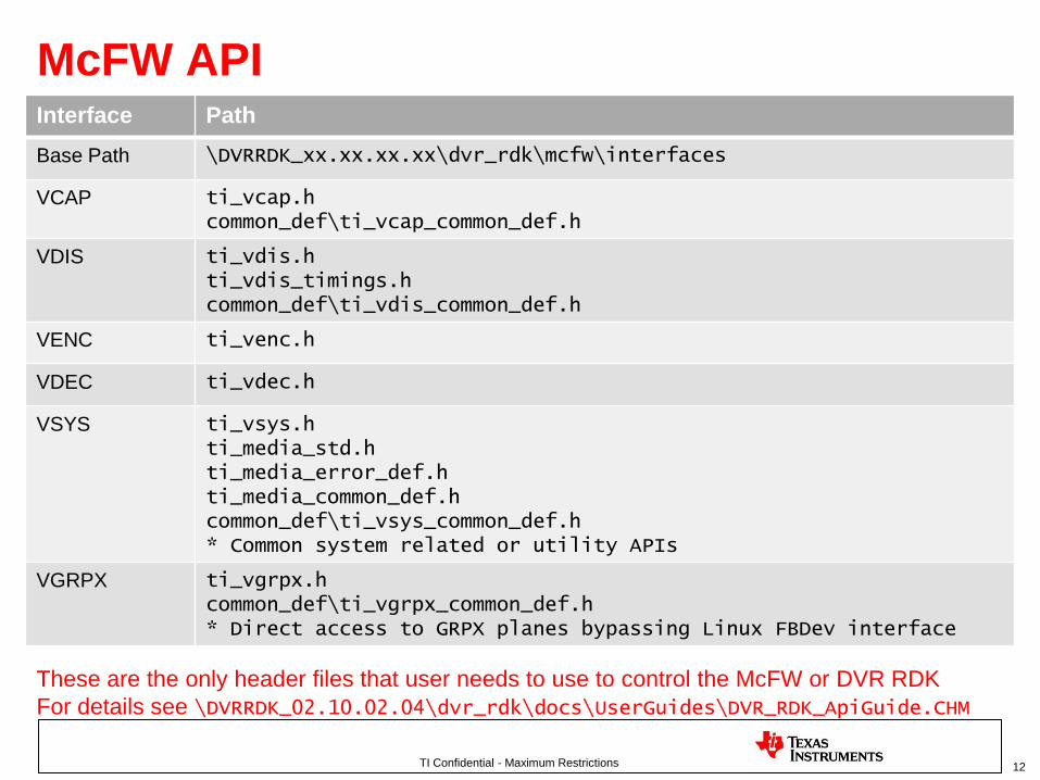
Interface Path
Base Path \DVRRDK_xx.xx.xx.xx\dvr_rdk\mcfw\interfaces
VCAP ti_vcap.hcommon_def\ti_vcap_common_def.h
VDIS ti_vdis.hti_vdis_timings.hcommon_def\ti_vdis_common_def.h
VENC ti_venc.h
VDEC ti_vdec.h
VSYS ti_vsys.hti_media_std.hti_media_error_def.hti_media_common_def.hcommon_def\ti_vsys_common_def.h* Common system related or utility APIs
VGRPX ti_vgrpx.hcommon_def\ti_vgrpx_common_def.h* Direct access to GRPX planes bypassing Linux FBDev interface
These are the only header files that user needs to use to control the McFW or DVR RDK
For details see \DVRRDK_02.10.02.04\dvr_rdk\docs\UserGuides\DVR_RDK_ApiGuide.CHM
TI Confidential - Maximum Restrictions
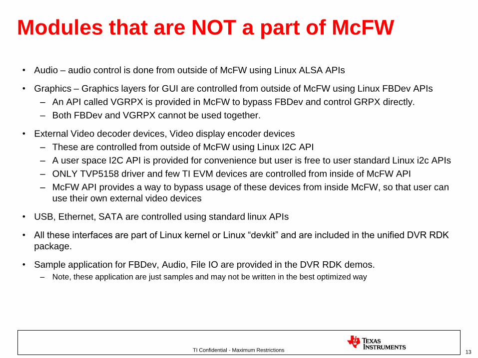
Modules that are NOT a part of McFW
• Audio – audio control is done from outside of McFW using Linux ALSA APIs
• Graphics – Graphics layers for GUI are controlled from outside of McFW using Linux FBDev APIs
– An API called VGRPX is provided in McFW to bypass FBDev and control GRPX directly.
– Both FBDev and VGRPX cannot be used together.
• External Video decoder devices, Video display encoder devices
– These are controlled from outside of McFW using Linux I2C API
– A user space I2C API is provided for convenience but user is free to user standard Linux i2c APIs
– ONLY TVP5158 driver and few TI EVM devices are controlled from inside of McFW API
– McFW API provides a way to bypass usage of these devices from inside McFW, so that user can
use their own external video devices
• USB, Ethernet, SATA are controlled using standard linux APIs
• All these interfaces are part of Linux kernel or Linux “devkit” and are included in the unified DVR RDK
package.
• Sample application for FBDev, Audio, File IO are provided in the DVR RDK demos.
– Note, these application are just samples and may not be written in the best optimized way
13

TI Confidential - Maximum Restrictions
VCAP - Features
• Captures multiple channels video data from external video devices like TVP5158
• De-interlaces and/or scales the video to generate multiple “streams” for each channel
• Each “stream” can have different resolution, frame-rate, OSD
• Upto 4 streams can be generated
– Live preview stream – usually 1:1 or lower resolution, used for live preview by VDIS
– Primary encode stream – usually 1:1 or lower resolution, used by VENC for primary
channel encode
– Secondary encode stream – usually lower resolution, used by VENC for secondary
channel encode
– Tertiary encode stream – used lower FPS, used by VENC for MJPEG encode
• Capabilities may vary depending on the use-case.
– See use-case guide for details of each use-case
(\DVRRDK_xx.xx.xx.xx\dvr_rdk\docs\Usecases)
14

TI Confidential - Maximum Restrictions
VCAP API – ti_vcap.h
15
API Description
Vcap_params_init Init data structure with default params
Vcap_init Init sub-system
Vcap_start Start sub-system
Vcap_stop Stop sub-system
Vcap_exit De-init sub-system
Vcap_enableChn Enable a specific channel in VCAP
Vcap_disableChn Disable a specific channel in VCAP
Vcap_setDynamicParamChn Set VCAP run-time parameters for a given channel stream
- Change width and height
- Change contrast, saturation, hue
- Control SW OSD parameters
- Control privacy masks
Vcap_setFrameRate Change frame-rate of capture channel stream
Given below are important VCAP APIs
Not all APIs are shown here for simplicity sake

TI Confidential - Maximum Restrictions
VDIS - Features
• Displays multiple channels from VCAP and/or VDEC
• Support up to three displays – 2x HD + 1x SD
• Support different user specified “mosaic”’s.
– Here multiple channels are shown on a single display based on user specified “windows”
• Scales the channels to generate different mosaic’s
• Mosaic’s can be changed on the fly including enable/disable of window/channel in a
mosaic
• Support dynamic change of display resolution
– i.e. display resolution can be changed without stopping other subsystems
• Capabilities may vary depending on the use-case.
– See use-case guide for details of each use-case
(\DVRRDK_xx.xx.xx.xx\dvr_rdk\docs\Usecases)
16
TI Confidential - Maximum Restrictions
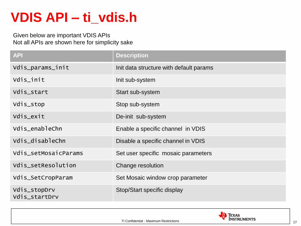
VDIS API – ti_vdis.h
17
API Description
Vdis_params_init Init data structure with default params
Vdis_init Init sub-system
Vdis_start Start sub-system
Vdis_stop Stop sub-system
Vdis_exit De-init sub-system
Vdis_enableChn Enable a specific channel in VDIS
Vdis_disableChn Disable a specific channel in VDIS
Vdis_setMosaicParams Set user specific mosaic parameters
Vdis_setResolution Change resolution
Vdis_SetCropParam Set Mosaic window crop parameter
Vdis_stopDrvVdis_startDrv
Stop/Start specific display
Given below are important VDIS APIs
Not all APIs are shown here for simplicity sake

TI Confidential - Maximum Restrictions
VENC - Features
• Encodes multiple channels from VCAP
• Support different streams of encode
– Primary encode – Typically - Full res, full FPS
– Secondary encode – Typically - Low res, full FPS
– Tertiary encode – Typically - Full res, Low FPS
• Support different video codecs – H264, MJPEG (MPEG4 encode NOT YET supported)
• Support dynamic change encode parameters like
– Resolution
– Frame-rate
– Bitrate
– I/P ratio, Rate control, Force I-frame, QP Value
• User specific callbacks to get notification on bitstream availability
• Capabilities may vary depending on the use-case.
– See use-case guide for details of each use-case
(\DVRRDK_xx.xx.xx.xx\dvr_rdk\docs\Usecases)
18

TI Confidential - Maximum Restrictions
VENC API – ti_venc.h
19
API Description
Venc_params_init Init data structure with default params
Venc_init Init sub-system
Venc_start Start sub-system
Venc_stop Stop sub-system
Venc_exit De-init sub-system
Venc_enableChn Enable a specific channel in VDIS
Venc_disableChn Disable a specific channel in VDIS
Venc_setDynamicParam Set run-time parameter for a given channel like
- frame-rate, bitrate, QP, RC algo etc
Venc_registerCallback Register user specified bitstream specification callback
Venc_getBitstreamBuffer Get encoded bitstream’s
Venc_releaseBitstreamBuffer Release encoded bistream buffer after they are used by
application
Given below are important VENC APIs
Not all APIs are shown here for simplicity sake

TI Confidential - Maximum Restrictions
VDEC - Features
• Decode multiple channels given by user and give to VDIS for display
• Support different video codecs – H264, MPEG4, MJPEG
• QCIF to 1080p resolution decode
• Support dynamic resolution change
• Support dynamic codec type change
• Trick play support – 1x, 2x, 4x, 8x, …. 1/2x, 1/4x …. Speeds
• I-frame only playback
• Support dynamic changing between SD and HD encode
– Example,
• 32CH D1 decode can be replaced dynamically by 6CH 1080p decode without closing the system
• Capabilities may vary depending on the use-case.
– See use-case guide for details of each use-case
(\DVRRDK_xx.xx.xx.xx\dvr_rdk\docs\Usecases)
20

TI Confidential - Maximum Restrictions
VDEC API – ti_vdec.h
21
API Description
Vdec_params_init Init data structure with default params
Vdec_init Init sub-system
Vdec_start Start sub-system
Vdec_stop Stop sub-system
Vdec_exit De-init sub-system
Vdec_enableChn Enable a specific channel in VDIS
Vdec_disableChn Disable a specific channel in VDIS
Vdec_createChnVdec_deleteChn
Dynamically create/delete a decode channel
Vdec_setTplayConfig Set trick play mode
Vdec_requestBitstreamBuffer Get buffer for decoding
Vdec_putBitstreamBuffer Give buffer for decoding
Given below are important VDEC APIs
Not all APIs are shown here for simplicity sake

TI Confidential - Maximum Restrictions
VSYS - Features
• Init, Create and delete a specific use-case
• Alloc and free contiguous buffer from common memory heap for user purpose
• Register user specific event handlers
– Example, for Scene change detect notification
• Capabilities may vary depending on the use-case.
– See use-case guide for details of each use-case
(\DVRRDK_xx.xx.xx.xx\dvr_rdk\docs\Usecases)
22

TI Confidential - Maximum Restrictions
VSYS API – ti_vsys.h
23
API Description
Vsys_params_init Init data structure with default params
Vsys_init Init overall McFW system
Vsys_create Create a use-case and be ready to start individual subsystems.
ONLY Vxxx_init() API must be called before this API.
Vxxx_start() APIs are called after this API.
Vsys_delete Delete a use-case.
ONLY Vxxx_exit () APIs can be called after this API.
Vxxx_stop() APIs are called before this API
Vsys_allocBufVsys_freeBuf
Alloc and free contiguous memory for user application
Vsys_registerEventHandler Register user specific event handler
Given below are important VSYS APIs
Not all APIs are shown here for simplicity sake

TI Confidential - Maximum Restrictions
McFW – Typical calling sequence –Startup phase
// Set Default paramsVsys_param_init(&vsysParams);Vcap_param_init(&vcapParams);Vdis_param_init(&vdisParams);Venc_param_init(&vencParams);Vdec_param_init(&vdecParams);
// init sub-systemsVsys_init(&vsysParams);Vcap_init(&vcapParams);Vdis_init(&vdisParams);Venc_init(&vencParams);Vdec_init(&vdecParams);
// create use-caseVsys_create();
// register user callbacksVenc_registerCallback(. . .);Vsys_registerEventHandler(. . .);
// start sub-systemsVdis_start();Venc_start();Vdec_start();Vcap_start();
24

TI Confidential - Maximum Restrictions
McFW – Typical calling sequence –Execution phase
// call McFW APIs as required
Vsys_allocBuf(. . .);
Vcap_setFrameRate(. . .);
Vcap_setDynamicParamChn(. . .);
Venc_setDynamicParam(. . .);
Vdis_setMosaicParams(. . .);
Venc_getBitstreamBuffer(. . .);
Venc_releaseBitstreamBuffer(. . .);
Vdec_requestBitstreamBuffer(. . .);
Vdec_putBitstreamBuffer(. . .);
Vsys_freeBuf(. . .);
25

TI Confidential - Maximum Restrictions
McFW – Typical calling sequence –Shutdown phase
// Stop subsystem’sVcap_stop();Vdis_stop();Venc_stop();Vdec_stop();
// delete use-caseVsys_delete();
// exit sub-systemVcap_exit();Vdis_exit();Venc_exit();Vdec_exit();Vsys_exit();
26

TI Confidential - Maximum Restrictions
More information on McFW
27
Info Location
Release
Notes, Build
and install
instructions
\DVRRDK_xx.xx.xx.xx\DM81xx_DVR_RDK_*.PDF
User Guide \DVRRDK_xx.xx.xx.xx\dvr_rdk\docs\UserGuides\DVR_RDK_McFW_UserGuide.pdf
API Guide \DVRRDK_xx.xx.xx.xx\dvr_rdk\docs\UserGuides\DVR_RDK_ApiGuide.CHM
Use-case
Guide’s
\DVRRDK_xx.xx.xx.xx\dvr_rdk\docs\Usecases
Specific
App Notes
\DVRRDK_xx.xx.xx.xx\dvr_rdk\docs\AppNotes
HW
Information
\DVRRDK_xx.xx.xx.xx\dvr_rdk\docs\Hardware
Sample
application
\DVRRDK_xx.xx.xx.xx\dvr_rdk\demos\mcfw_api_demos\mcfw_demo

TI Confidential - Maximum Restrictions 28
Agenda
• Introduction to DVR RDK
• McFW API
•Link API and Architecture Overview
• Links – Features
• Links Architecture – Deep Dive

TI Confidential - Maximum Restrictions
Link API
• A link is the basic processing unit in a video data flow.
– A link consists of a BIOS6/Linux thread coupled with a message box (implemented using OS
semaphores).
– Since each link runs as a separate thread, links can run in parallel to each other.
– The message box associated with a link allows user application as well as other links to talk to
that link.
– The link implements a specific interface which allows other links to exchange video frames and/or
bit streams with the link.
• Link API allows user to create, control and connect the links.
• McFW API uses Link API to make a “chain” or use-case depending on the top level
system configuration provided by the user.
• Alternatively user’s can use the link API directly to make custom use-cases not supported
by the McFW API.
• NOTE: Most users don’t need to know low level details of the internal software
architecture, but it useful to know how the software operates internally in order to get the
most out of the system.
29

TI Confidential - Maximum Restrictions 30
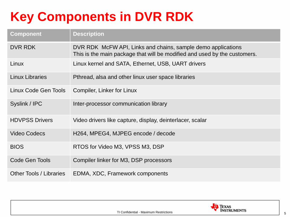
Link Block Diagram
<ModuleName>
Link
IN Queue 0 OUT Queue 0
Array
Based
Queue
ListMP + Notify
+ Shared Region
• Cmds
• NEW_DATA
• FORCE_RESET etc
• Functions
• tskRun
• getFullFrames
• putEmptyFrames etc
• InstId
• prevId
• nextId
• Constituent
• <ModuleName>_drv.c
• <ModuleName>_tsk.c
IN Queue N OUT Queue N
… … …
… … …
… … …
… … …
Note #1 : Each processing
component in data flow
corresponds to
one Link in the architecture
e.g. captureLink, decLink,
displayLink etc.
Note #2 : Each link can have
multiple instances
and
every instance of a
Link supports this
architecture
Note #3 : Every Link instance
can be connected
to other link instance
on the same core
or
on the remote core
IpcInM3/IpcOutM3

TI Confidential - Maximum Restrictions
Link Distribution
31
Processor OS Used for
HOST A8 Linux System setup and control, GUI, IO peripheral controllike SATA, Ethernet, USB, Audio
VPSS M3 BIOS6 HDVPSS control for video capture, video display,scaling, de –interlacing
Video M3 BIOS6 HDVICP2 Video compression / decompression (H264encode, H264 decode)
DSP BIOS6 SW OSD, custom video processing algorithms
The video processing workload is divided between different processors as shown
below

TI Confidential - Maximum Restrictions
Basic’s of Link operation
• Within each processor, each processing step like capture or display will run in its own
independent thread. Such a independent thread of execution is called a “link” in this
framework.
– Example links include, capture, display, DEI, Noise Filter, encode, decode
• Each thread or link is capable of handling processing of video frames from multiple
channels, each having different properties like width, height, data format etc.
• A link will “connect” to other links to make a chain or a data flow. This connection and
control can be done by the user from the HOST A8 side.
• Once a chain is setup and started, each link in the chain will exchange frames will its next
link, using a well defined interface, to make the video processing data flow.
• The framework allows links on different processors to exchange frames directly with each
other without any intervention of the HOST A8.
• Once a chain is running, user can send control commands to individual links to control
their run-time behavior. Example, changing Mosaic layout for the display.
32

TI Confidential - Maximum Restrictions
Simple example of links connected to form a chain or use-case
33
Capture
Noise Filter
SW Mosaic
(DEI)
Display
16CH 720x240 YUV422I 60fps
16CH 720x240 YUV420SP 60fps
1CH 1920x1080 YUV422I 60fps (1080p60)
4x4 Mosaic Layout

TI Confidential - Maximum Restrictions
Actual 16D1 Encode use-case using links
34

TI Confidential - Maximum Restrictions 35
List of Links
• M3 Video
– Encoder
– Decoder
• M3 Vpss
– Capture
– Display
– Noise Filter
– Scalar
– De-Interlace
– Grpx
– SW Mosaic
• Dsp
– Alg Link• OSD (On Screen Display)
• SCD (Scene change Detection)
• IPC Links
– IPC M3 In/Out
– IPC Frames In/Out
– IPC Bitstream In/Out
• Connector links
– Merge
– Dup
– Select
• System Links
– M3 VPSS
– M3 Video
– DSP

TI Confidential - Maximum Restrictions
SW Block Diagram
36
Linux BIOS6
Syslink / IPCSyslink / IPC
HDVPSS
Drivers
BIOS6
Syslink / IPC
Video Encode /
Decode
BIOS6
Syslink / IPC
DSKT2
Links
Capture,
Display,
SW Mosaic
…
Links
Encode
Decode
…
Links
SW OSD,
…
Links
Bitstream IN
Bitstream OUT
…
Link API
McFW API
User application
HOST A8 VPSS M3 Video M3 DSP
User API Advanced User
APILowest Level HW
API
CPUs
OSes
Link Implementation

TI Confidential - Maximum Restrictions 37
Frame information structure
Frame Buffer
(Video frame
data)
FVID2 Header
channelNum
Addr[ ][ ]
perFrameCfg
AppData
timeStamp
… …
… …
… …
… …
• Links exchange
FVID2_Frame information
structure’s with each other.
• The frame buffers (video
data) can be sent across
processors for processing
using these FVID2_Frame
info structures.
•The FVID2_Frame has
sufficient information that
can be used to transport
frame buffers.

TI Confidential - Maximum Restrictions 38
Inter-Link communication / Data transfer
• In the Link based architecture, SW queues used to transfer data across links.
• The following three inter link frame exchange mechanisms are used
• Intra-processor links
– Example, from capture to noise filter which run on the same processor.
– Simple and efficient array based queue’s are used for frame exchange.
• Inter M3 (Video / VPSS) links
– Example from NF to encode (via IPC M3 OUT/IN Link) which run on VPSS M3 and Video M3 (sharing a uni-cache).
– IPC ListMP with Notify is used with frame information pointer (FVID2_Frame) being passed directly without any cache operations and address translation since both M3 share the same uni-cache.
• Inter processor (M3 to A8 or DSP)
– Example from encode to Bitstream IN (via IPC OUT/IN Link) which run on Video M3 and Host A8.
– This type of communication is achieved using ListMP, Notify and Shared Region modules from SysLink component.
– M3 side cache operations are performed using BIOS cache APIs
– A8 side cache operations are performed using SysLink cache APIs

TI Confidential - Maximum Restrictions
More information on Link API
39
Info Location
Interface \DVRRDK_xx.xx.xx.xx\dvr_rdk\mcfw\interfaces\link_api\DVRRDK_xx.xx.xx.xx\dvr_rdk\mcfw\interfaces\common_def
User Guide \DVRRDK_xx.xx.xx.xx\dvr_rdk\docs\UserGuides\DVR_RDK_McFW_UserGuide.pdf
API Guide \DVRRDK_xx.xx.xx.xx\dvr_rdk\docs\UserGuides\DVR_RDK_ApiGuide.CHM
Use-case
Guide’s
\DVRRDK_xx.xx.xx.xx\dvr_rdk\docs\Usecases
Specific
App Notes
\DVRRDK_xx.xx.xx.xx\dvr_rdk\docs\AppNotes
Sample
usage of
link API
\DVRRDK_xx.xx.xx.xx\dvr_rdk\mcfw\src_linux\mcfw_api\usecases

TI Confidential - Maximum Restrictions 40
Agenda
• Introduction to DVR RDK
• McFW API
• Link API and Architecture Overview
•Links – Features
• Links Architecture – Deep Dive

TI Confidential - Maximum Restrictions
Common Features of all Links
• All links are capable of multi channel operation
• All links can be instantiated multiple times (except capture, encode,
decode)
• User can specific number of output buffers to allocate at each link. Thus
allowing user control over memory usage(SYSTEM_LINK_FRAMES_PER_CH )
• All links support at least one input queue (except capture) to receive
frames and at least one output queue to put the processed frames
(except display)
• Where ever HW supports Tiler mode of operation, the link support a
means to enable or disable tiler usage.
– Using Tiler saves DDR BW for encode/decode at the cost increased
restrictions on memory allocation
• Each CH can have different properties like W x H, data format, FPS etc
41
TI Confidential - Maximum Restrictions
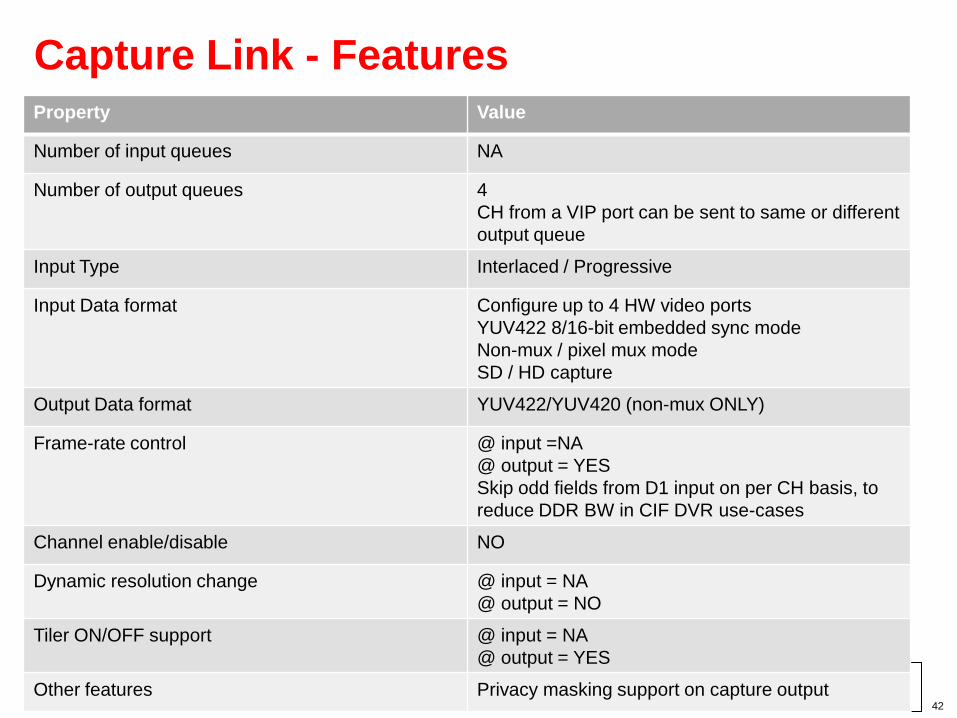
Capture Link - Features
42
Property Value
Number of input queues NA
Number of output queues 4
CH from a VIP port can be sent to same or different
output queue
Input Type Interlaced / Progressive
Input Data format Configure up to 4 HW video ports
YUV422 8/16-bit embedded sync mode
Non-mux / pixel mux mode
SD / HD capture
Output Data format YUV422/YUV420 (non-mux ONLY)
Frame-rate control @ input =NA
@ output = YES
Skip odd fields from D1 input on per CH basis, to
reduce DDR BW in CIF DVR use-cases
Channel enable/disable NO
Dynamic resolution change @ input = NA
@ output = NO
Tiler ON/OFF support @ input = NA
@ output = YES
Other features Privacy masking support on capture output

TI Confidential - Maximum Restrictions
DEI Link - Features
43
Property Value
Number of input queues 1
Number of output queues 3
DEI-SC YUV422 output
VIP-SC (0) – YUV420/YUV422 output
VIP-SC (1) – YUV420/YUV422 output
Input Type Interlaced / Progressive
Input Data format YUV422/YUV420
Output Data format YUV422/YUV420
Frame-rate control @ input = YES
@ output = YES
Channel enable/disable YES
Dynamic resolution change @ input = NO
@ output = YES
Tiler ON/OFF support @ input = YES
@ output = YES
Other features Line skip mode for low DDR BW
Different output scaling factor
4FLD / 5FLD DEI or DEI in bypass mode

TI Confidential - Maximum Restrictions
Scalar Link - Features
44
Property Value
Number of input queues 1
Number of output queues 1
Input Type Interlaced / Progressive
Input Data format YUV422/YUV420
Output Data format YUV422
Frame-rate control @ input = YES
@ output = YES
Channel enable/disable YES
Dynamic resolution change @ input = YES
@ output = YES
Tiler ON/OFF support @ input = YES
@ output = NA
Other features Line skip mode for low DDR BW
Different output scaling factor
Field skip mode for low DDR BW

TI Confidential - Maximum Restrictions
Noise Filter Link - Features
Property Value
Number of input queues 1
Number of output queues 2
Incoming channels can split into two different
output queues
Input Type Interlaced / Progressive
Input Data format YUV422
Output Data format YUV420
Frame-rate control @ input = YES
@ output = YES
Channel enable/disable NO
Dynamic resolution change @ input = YES
@ output = YES
Tiler ON/OFF support @ input = NA
@ output = YES
Other features NF mode or NF bypass mode
Field skip mode for low DDR BW
45

TI Confidential - Maximum Restrictions
SW Mosaic Link - Features
46
Property Value
Number of input queues 1
Number of output queues 1
Input Type Interlaced / Progressive
Input Data format YUV422/YUV420
Output Data format YUV422
Frame-rate control @ input = YES
@ output = YES
Channel enable/disable YES
Dynamic resolution change @ input = YES
@ output = YES
Tiler ON/OFF support @ input = YES
@ output = NA
Other features User specified SW Mosaic windows
Multiple scaler in single SW mosaic instance
Field skip mode for low DDR BW
Line skip mode for low DDR BW

TI Confidential - Maximum Restrictions
Display Link - Features
47
Property Value
Number of input queues 2
Number of output queues NA
Input Type Interlaced / Progressive
Input Data format YUV422/YUV420
Output Data format HDMI, HDDAC, DVO2, SDTV
Frame-rate control @ input = NA
@ output = NA
Channel enable/disable YES
Dynamic resolution change @ input = YES
@ output = NA
Tiler ON/OFF support @ input = YES
@ output = NA
Other features Switching between input queues

TI Confidential - Maximum Restrictions
Graphics Link - Features
48
Property Value
Number of input queues 1
Number of output queues NA
Input Type Interlaced/Progressive
Input Data format RGB565, ARGB888
Output Data format HDMI, HDDAC, DVO2, SDTV
Frame-rate control @ input = NA
@ output = NA
Channel enable/disable NA
Dynamic resolution change @ input = YES
@ output = NA
Tiler ON/OFF support @ input = NA
@ output = NA
Other features Scaling ON/OFF
Transparency ON/OFF
Screen Position setting

TI Confidential - Maximum Restrictions
Encode Link - Features
49
Property Value
Number of input queues 1
Number of output queues 1
Input Type Interlaced/Progressive
Input Data format YUV420
Output Data format H264 encode
MJPEG encode
Frame-rate control @ input = YES
@ output = NA
Channel enable/disable YES
Dynamic resolution change @ input = YES
@ output = NA
Tiler ON/OFF support @ input = YES
@ output = NA
Other features Bitrate control, IP ratio control, force I-frame, RC
algo control, profile (BP/MP/HP) level control, QP
setting, snapshot mode

TI Confidential - Maximum Restrictions
Decode Link - Features
50
Property Value
Number of input queues 1
Number of output queues 1
Input Type Interlaced/Progressive
Input Data format H264 decode
MJPEG decode
MPEG4 decode
Output Data format YUV420
Frame-rate control @ input = NA
@ output = YES
Channel enable/disable YES
Dynamic resolution change @ input = YES
@ output = NA
Tiler ON/OFF support @ input = YES
@ output = NA
Other features Dynamic channel create / delete

TI Confidential - Maximum Restrictions
DSP Algorithm Link – Features – OSD Algorithm
51
Property Value
Number of input queues 1
Number of output queues 1
Input Type Interlaced/Progressive
Input Data format YUV422/YUV420
Output Data format YUV422/YUV420
Frame-rate control @ input = NA
@ output = NA
Channel enable/disable NA
Dynamic resolution change @ input = YES
@ output = YES
Tiler ON/OFF support @ input = YES
@ output = YES
Other features Control for Number of OSD windows, OSD Window
size, position, transparency color, window
enable/disable

TI Confidential - Maximum Restrictions
DSP Algorithm Link – Features – SCD (Scene Change Detect) Algorithm
52
Property Value
Number of input queues 1
Number of output queues 1
Input Type Interlaced/Progressive
Input Data format YUV422/YUV420
Output Data format Block level Motion info and/or user Notification on
Scene change detect
Frame-rate control @ input = YES
@ output = NA
Channel enable/disable NA
Dynamic resolution change @ input = YES
@ output = YES
Tiler ON/OFF support @ input = YES
@ output = NA
Other features Frame level or block level scene change detect
Control for scene change sensitivity, block sizes

TI Confidential - Maximum Restrictions 53
Additional Links
• To achieve the data flow for multiple possible use cases, having only video processing links is not sufficient
• We need following additional Links other than video processing links
– dupLink
– mergeLink
– selectLink
– ipcBitsInLinkHLOS
– ipcBitsOutLinkHLOS
– ipcBitsInLinkRTOS
– ipcBitsOutLinkRTOS
– ipcFrameinLinkHLOS
– ipcFrameOutLinkHLOS
– ipcFrameInLinkRTOS
– ipcFrameOutLinkRTOS

TI Confidential - Maximum Restrictions 54
Additional Links (continued..)
• Dup Link - why exactly it is needed?
DEI
SWMS 0
SWMS 1
HDMI 0
HDMI 1
SD
refCount
Info memcpy
dupLink
dupLink

TI Confidential - Maximum Restrictions
Additional Links (continued..)
• Merge Link
– Given N in put streams it produces single output stream.
– No memcpy of information is involved in merge
– It has a pre-mapped input to output channel table
55
DEI
DEIH
merge16 ch CIF YUV420
8 CIF YUV420
8 CIF YUV420
8 D1 YUV422
8 D1 YUV422

TI Confidential - Maximum Restrictions
Additional Links (continued..)
• Select Link
– Allows user to “select” channels at the output queues at run time.
– Select link can have maximum 6 output queues and which input channel
goes to which output queue is controllable from use case application through
SELECT_LINK_CMD_SET_OUT_QUE_CH_INFO
– The Link can have instances on M3Video, M3Vpss and Dsp
– Example
56
Capture Select
DEI
DEIH
o/p Que 0
o/p Que 1
16
8
4
{ch no 2,5,8,9}
{ch no 1,3,4,6,7,
10,11,12}
Note : Data Buffers corresponding to Channels which are not sent/mapped
on any of output queues are sent back by SelectLink

TI Confidential - Maximum Restrictions 57
Additional Links (continued..)
• ipcBits In/Out Link for RTOS/HLOS
– Used to send and receive bit stream across processors
ENC ipcBitsOut readerThreadipcBitsIn
DEC ipcBitsIn writerThreadipcBitsOut
HDD
Network
A8M3Video
Bit
stream
Bit
stream

TI Confidential - Maximum Restrictions 58
Additional Links (continued..)
• ipcFrames In/Out Link for HLOS/RTOS
– Used send and receive frames across processors
DEI
SWMS
M3VPSS
ipcFrameOut
OSD
ipcFrameIn
DSP

TI Confidential - Maximum Restrictions 59
ipcFrameOut Link – different implementation
• ipcFrames In/Out Link for HLOS/RTOS
– Used send and receive frames across processors
ipcFrameOutHLOS/RTOS
Prev Link Next Link
Process Link
Received output is
Given to next link
This saves additional
ipcFramesOut on the
Other end
Apart from
Prev Link
And Next Link
This link has
Process Link as
Bidirectional data queue
Which is actually connected to
ipcFramesIn on the
remote core

TI Confidential - Maximum Restrictions 60
Agenda
• Introduction to DVR RDK
• McFW API
• Link API and Architecture Overview
• Links – Features
•Links Architecture – Deep Dive

TI Confidential - Maximum Restrictions
Links Architecture – Deep Dive
• Example Link Control/Data Flow – DEI, SW Moisac, Enc/Dec
• Enc/Dec Link Details
61

TI Confidential - Maximum Restrictions
Example Link Control/Data Flow
62

TI Confidential - Maximum Restrictions 63
Example, M3VPSS Links: DEI
Input Full Q
Input Empty Q
CH1Q
CH2Q
CHNQ
DEI Tsk
Output Empty Q
DEI LinkOut Buffer pool
To out que
of Link
Driver
Driver
callBacksem
post
sem
pend
inBuf, opBuf
Submitted to drv

TI Confidential - Maximum Restrictions 64
Example, M3VPSS Links: SW Mosaic (SWMS)
Input Full Q
Input Empty Q
CH1Q
CH2Q
CHNQ
SWMS Tsk
Output Empty Q
SWMS Link
Out Buffer pool
Driver
To out Q
of Link
Clk Object
(to submit
Buffers
periodically)
Driver
callBack
sem
pend
sem
post
inBuf, opBuf
Submitted to drv

TI Confidential - Maximum Restrictions
Enc/Dec Link Details
65

TI Confidential - Maximum Restrictions 66
Example, M3VIDEO Links: ENC/DEC
Input Full Q
Input Empty Q
CH1Q
CH2Q
.
CHNQ
ENC/DEC Tsk
IVA Processing
Tasks (0,1 & 2)
IVA0 Process Q
ProcessDone Q
CLK Obj
HD
720p
D1
CIF
Output Full Q
OP BUF
POOL
IVA0
IVA1
IVA2
CH2IVA
MAP TBL
ENC/DEC Link
IVA Server
IVA1 Process Q
IVA2 Process Q
Bunch Submission
Bunch Submission
Bunch Submission
Output Empty Q

TI Confidential - Maximum Restrictions 67
ENC/DEC Link – Threading Model
• ENC/DEC link architecture:
– In Video M3, encoder and decoder are the two main links and each integrates codec and IVA-HD scheduler
– I/O interface• Input: Has one input frame Full Q from previous link which feeds the link
• Input: One empty frame Q part of previous link to free the processed input
• Output: Has one output buffer Full Q to send out the processed data
• Output: One or more empty buffer Q to receive the free frames from the next link
– Encoder and decoder links are exactly same. Only difference is they integrate different codecs and they take different input and output.
– Enc/Dec links have one link task, three processing tasks – one for each IVA - and one periodic task

TI Confidential - Maximum Restrictions 68
ENC/DEC Link – Threading Model (cont.)
• Enc Link Task: – Responsible for command/data processing events– A single task which reads the input data– Create the multi-channel process list and submit the same to the IVA specific process
Queue– Send out or free the output buffer frames
• IVA Processing Tasks:– One IVA Processing Task per IVA-HD for Encoder /DecoderLinks– Reads the process list from its process Queue– Populates the multi-codec params by populating the arguments such as inArgs, outArgs,
inBuffs & outBufs for each channels– Invokes the multi-codec .process call– And finally once the codec complete its process call , it puts the processed buffer’s in to its
“process done” Queue
• Periodic Clock Object:– This a BIOS clock object runs periodically and posts the “GET_PROCESSED_DATA “
event
• Task priority:– All these tasks runs concurrently– IVA Processing Tasks has the highest priority followed by Enc Link Task & Clock Object – By making the IVA processing task as the highest priority ones ensures the IVA usage to
the maximum

TI Confidential - Maximum Restrictions 69
ENC/DEC Link – Data Flow
• Step1: Enc Link Task:
– Data processing kick starts once the Enc link task receives the data event
“SYSTEM_CMD_NEW_DATA”
– Reads the input data from the input FULL Queue
– Put the frames in Enc Link channel specific queue
– Checks for the output buffer availability
– If output buffer available de-queue the input frame from channel specific queue
– De-queue an output buffers from the common output buffer pool
– Create the channel process list (a container holds the input frame & output buffer)
– Create multichannel process list and put into the appropriate IVA process queue.
– An IVA channel Map applied from the application context will decides the Enc link to put the
process list to which IVA process queue.
• Step2: IVA process Task:
– De-queue the multichannel process list from its input process queue
– Populates the multi-codec ProcessParamsList and ProcessParams by populating the arguments
such as inArgs, outArgs, inBuffs & outBufs for each channels
– Call the XDM multi codec process call and wait (XDM .process is a blocking call)
– Put the process list into the common process done Queue once the encode process complete.
Process done queue is common across all the 3 IVAs

TI Confidential - Maximum Restrictions 70
ENC/DEC Link – Data Flow (cont.)
• Step3: Periodic Clock Object:
– This periodic clock object post the data event ENC_LINK_CMD_GET_PROCESSED_DATA to the
Enc Link Task
• Step4: Enc Link Task:
– On receiving the ENC_LINK_CMD_GET_PROCESSED_DATA message, its De-queue the process list from its process Done queue
– Send out the output buffer to the next link, by putting them into the outputs Full Queue
– Free the input frames by putting the same in the input Empty Queue

TI Confidential - Maximum Restrictions 71
ENC/DEC Link – Data Flow (cont.)
• A few other notable points
– The Link architecture & data flow of the decoder link is exactly same as encoder link, hence NOT discussed separately
– Each IVA will have to process from a MAX of TWO process Queues when both encoder & decoder channels are mapped to the same IVA
– Enc/Dec links can work in Tiled as well as Non Tiled format
– Enc/Dec link uses the Framework Component (FC) iresman API to acquire and release the IVA-HDs
– Data structures for multi-codec process APIs as below
typedef struct {
IVIDENC2_Handle handle;
IVIDEO2_BufDesc *inBufs;
XDM2_BufDesc *outBufs;
IVIDENC2_InArgs *inArgs;
IVIDENC2_OutArgs *outArgs;
} IH264ENC_ProcessParams;
typedef struct {
XDAS_Int32 numEntries ;
IH264ENC_ProcessParams processParams
[IH264ENC_MAX_LENGTH_PROCESS_LIST];
} IH264ENC_ProcessParamsList ;

TI Confidential - Maximum Restrictions 72
ENC/DEC Link – IVA Channel Map
IVA allocation Table:– This helps the app to allocate/distribute different channels to different IVA-HDs as per
their wish
– This a table that can be set from Application on A8 side (inside McFW use-case)
– Enables to use the single Video M3 binaries for different use-cases without needed to rebuild
– Reduces the Video M3 side complexity and gives flexibility to app integrator
– Efficient mapping reduces the codec/data reload overheads
– Data structure of IVA channel map & IVA allocation table as below
typedef struct SystemVideo_Ivahd2ChMap { UInt32 EncNumCh;/**< Number of Encoder channels */ UInt32 EncChList[SYSTEMVIDEO_MAX_IVACH]; /**< Encoder channel list */ UInt32 DecNumCh; /**< Number of Decoder channels */ UInt32 DecChList[SYSTEMVIDEO_MAX_IVACH];/**< Decoder channel list */
} SystemVideo_Ivahd2ChMap;
typedef struct SystemVideo_Ivahd2ChMap_Tbl { UInt32 isPopulated; /**< Flag to verify if the table is populated */ SystemVideo_Ivahd2ChMap ivaMap[SYSTEMVIDEO_MAX_NUMHDVICP];/**< Structure to assign the video channels to all 3 IVA-HDs */
} SystemVideo_Ivahd2ChMap_Tbl;

TI Confidential - Maximum Restrictions 73
Thank you !!!