DVL EF Fireplace Owner's Manual - Lopi
46
DVL EF Fireplace Owner's Manual Featuring the Burner Tested and Listed by OMNI-Test Laboratories, Inc. Beaverton, Oregon Report # 028-S-23B-5 ANSI Z21.88 • Built-In Direct Vent Fireplace • Natural Gas or Propane • Residential or Mobile Home WARNING: If the information in these instructions is not followed exactly, a fire or explosion may result causing property damage, personal injury or loss of life. - Do not store or use gasoline or other flammable vapors and liquids in the vicinity of this or any other appliance. WHAT TO DO IF YOU SMELL GAS • Do not try to light any appliance. • Do not touch any electrical switch; do not use any phone in your building. • Immediately call gas supplier from a neighbor's phone. Follow the gas supplier's instructions. • If you cannot reach your gas supplier, call the fire department. - Installation and service must be performed by a qualified installer, service agency or the gas supplier. This appliance may be installed as an OEM installation in a manufactured (mobile) home and must be installed in accordance with the manufacturer’s instructions and the manufactured home construction and safety standard, Title 24 CFR, Part 3280. This appliance is only for use with the type(s) of gas indicated on the rating plate. A conversion kit is supplied with the appliance. Installer: After installation give this manual to the home-owner and explain operation of this heater. Copyright 2005, Travis Industries, Inc. $10.00 100-01147 Travis Industries, Inc. 4800 Harbour Pointe Blvd. SW Mukilteo, WA 98275
Transcript of DVL EF Fireplace Owner's Manual - Lopi

DVL EF Fireplace Owner's Manual
Featuring the
Burner
Tested and Listed by
OMNI-Test Laboratories, Inc.Beaverton, Oregon
Report # 028-S-23B-5ANSI Z21.88
• Built-In Direct Vent Fireplace
• Natural Gas or Propane
• Residential or Mobile Home
WARNING: If the information in these instructions is not followed exactly, a fire orexplosion may result causing property damage, personal injury or loss of life.
- Do not store or use gasoline or other flammable vapors and liquids in the vicinity of this or anyother appliance.
WHAT TO DO IF YOU SMELL GAS• Do not try to light any appliance.• Do not touch any electrical switch; do not use any phone in your building.• Immediately call gas supplier from a neighbor's phone. Follow the gas supplier's instructions.• If you cannot reach your gas supplier, call the fire department.
- Installat ion and service must be performed by a qualified installer, service agency or the gassupplier.
This appliance may be installed as an OEM installation in a manufactured (mobile) home andmust be installed in accordance with the manufacturer’s instructions and the manufactured homeconstruction and safety standard, Title 24 CFR, Part 3280.
This appliance is only for use with the type(s) of gas indicated on the rating plate. Aconversion kit is supplied with the appliance.
Installer: After installation give this manual to the home-ownerand explain operation of this heater.
Copyright 2005, Travis Industries, Inc. $10.00 100-01147
Travis Industries, Inc.4800 Harbour Pointe Blvd. SW
Mukilteo, WA 98275

2 Introduction
Travis Industries 4041206 100-01147
Introduction
We welcome you as a new owner of a Travis Industries gas fireplace. In purchasing this fireplace youhave joined the growing ranks of concerned individuals whose selection of an energy system reflectsboth a concern for the environment and aesthetics. The Travis Industries DVL EF Fireplace is one ofthe finest home heaters the world over. This manual will explain the installation, operation, andmaintenance of this fireplace. Please familiarize yourself with the Owner's Manual before operatingyour heater and save the manual for future reference. Included are helpful hints and suggestions thatwill make the operation and maintenance of your new fireplace an easier and more enjoyableexperience. We offer our continual support and guidance to help you achieve the maximum benefitand enjoyment from your heater.
Important InformationNo other DVL EF gas fireplace has the same serialnumber as yours. The serial number is below and tothe left of the gas control valve.
This serial number will be needed in case you requireservice of any type.
Model: DVL EF Fireplace
Serial Number:
Purchase Date:
Purchased From:
Mail your Warranty CardToday, and Save Your Bill ofSa le .
To receive full warranty coverage,you will need to show evidence ofthe date you purchased yourheater. Do not mail your Bill ofSale to us.
We suggest that you attach yourBill of Sale to this page so that youwill have all the information youneed in one place should the needfor service or information occur.

Table of Contents 3
Travis Industries 4041206 100-01147
IntroductionIntroduction & Important Information................2
Safety PrecautionsSafety Precautions ......................................4
Features & SpecificationsFeatures ....................................................6Installation Options......................................6Heating Specifications..................................6Dimensions.................................................6
InstallationInstallation Warning......................................7Packing List................................................7Additional Items Required for Installation..........7Installation Overview....................................7Fireplace Placement Requirements..................8
Minimum Framing Dimensions ....................8Clearances ............................................8Corner Installations .................................9Raised Fireplaces....................................9
Hearth Requirements....................................10Facing Requirements....................................11Facing Over 1" Thick.....................................11Facing Detail ...............................................12Face Dimensions .........................................13Modifying the Face Angle...............................14Facing & Hearth Examples.............................15Mantel Requirements....................................17Vent Requirements.......................................18
Altitude Considerations ............................18Clearances ............................................18Use of 8” Dia. Pipe...................................18Vent Installation......................................19
Approved Vent Configurations........................20Restrictor Position...................................20Measuring Vent Lengths...........................20Vertical Terminations (with/ without offsets)..21Vertical Terminations with 2 90° Elbows........22Horizontal Terminations w/ 1 Vertical Elbow ..23Horizontal Terminations w/ 3 Vertical Elbows.24
Vent Termination Requirements ......................25Gas Line Requirements.................................26
Fuel ......................................................26Gas Line Connection................................26Gas Inlet Pressure ..................................26
Electrical Connection....................................27
Finalizing the Installation1 Glass Removal (& installation)......................282 Log & Coal Installation................................303 Purge Gas Line and Replace the Glass ..........314 Faceplate Installation.................................315 Leak Test.................................................316 Pilot Adjustment (if necessary).....................317 Air Shutter Adjustment (if necessary) ............318 Check Flame.............................................329 Explain Operation to Home-Owner.................32
OperationBefore You Begin.........................................33Location of Controls .....................................33Starting The Pilot .........................................34Starting the Fireplace for the First Time.............35Turning the Fireplace On and Off .....................35Adjusting the Flame Height.............................35Adjusting the Blower Speed............................36Normal Operating Sounds..............................36Normal Operating Odors................................36
MaintenanceYearly Service Procedure..............................37Troubleshooting Table...................................38How this Fireplace Works...............................39
What Turns the Main Burners On and Off......39What Prevents Gas Buildup.......................39
Wiring Diagram ............................................40Replacement Parts List .................................40
Safety LabelSafety (Listing) Label....................................41
WarrantyWarranty ....................................................42
Optional EquipmentLP Conversion Kit ........................................43
Index Index.........................................................46

4 Safety Precautions
Travis Industries 4041206 100-01147
• IF YOU SMELL GAS:* Do not light any appliance
* Extinguish any open flame
* Do not touch any electrical switch or plug or unplug anything
* Open windows and vacate building
* Call gas supplier from neighbor's house, if not reached, call firedepartment
• This unit must be installed by a qualified installer to prevent the possibility of anexplosion. Your dealer will know the requirements in your area and can inform you ofthose people considered qualified. The room heater should be inspected andcleaned before use and at least annually by a qualified service person. More frequentcleaning may be required due to excessive lint from carpeting, bedding material, etc.
• The instructions in this manual must be strictly adhered to. Do not use makeshiftmethods or compromise in the installation. Improper installation will void the warrantyand safety listing.
For LPG only | Pout 11” W.C.
Look for this label:
If the label is present, the heater is equipped for LP (propane). If the label is absent, the heater is equipped for NG (natural gas).
• This heater is either approved for naturalgas (NG) or for propane (LP). Burning theincorrect fuel will void the warranty andsafety listing and may cause an extremesafety hazard. Direct questions about thetype of fuel used to your dealer. Checkthe label and flame adjust knob on thegas control valve.
Ok
• Contact your local buildingofficials to obtain a permitand information on anyinstallation restrictions orinspection requirements inyour area. Notify yourinsurance company of thisheater as well.
• If the flame becomes sooty,dark orange in color, orextremely tall, do notoperate the heater. Callyour dealer and arrange forproper servicing.
AAAAAAA
• It is imperative that controlcompartments, screens, orcirculating air passagewaysof the heater be kept cleanand free of obstructions.These areas provide the airnecessary for safeoperation.
?• Do not operate the heater if
it is not operating properly inany fashion or if you areuncertain. Call your dealerfor a full explanation of yourheater and what to expect.
Gas
• Do not store or use gasolineor other flammable liquids inthe vicinity of this heater.
AAAAAAAAAAAAAAA
AAAAAAAAAAAAAAAAAAA
• Do not operate if any portion ofthe heater was submerged inwater or if any corrosionoccurs. Immediately call aqualified service technician toinspect the appliance and toreplace any part of the controlsystem and any gas controlwash has been under water.

Safety Precautions 5
Travis Industries 4041206 100-01147
• Do not place clothing orother flammable items on ornear the heater. Becausethis heater can be controlledby a thermostat there is apossibility of the heaterturning on and igniting anyitems placed on or near it.
AAAAAAAAA
• Light the heater using thebuilt-in piezo igniter. Do notuse matches or any otherexternal device to light yourheater.
• Never remove, replace,modify or substitute any partof the heater unlessinstructions are given in this
• The viewing glass should beopened only for lighting thepilot or conducting service.Do not operate with cracked,broken, or removed glass.
• Any safety screen or guardremoved for servicing mustbe replaced prior tooperating the heater.
manual. All other work mustbe done by a trainedtechnician. Don't modify orreplace orifices.
• Allow the heater to coolbefore carrying out anymaintenance or cleaning.
• Operate the heateraccording to the instructionsincluded in this manual.
• If the main burners do notstart correctly turn the gasoff at the gas control valveand call your dealer forservice.
• The pilot flame must contactthe thermopile andthermocouple (see theillustration to the left). If itdoes not, turn the gascontrol valve to "OFF" andcall your dealer.
AAAAAAAA
• This unit is not for use withsolid fuel
• Do not place anything insidethe firebox (except theincluded fiber logs).
• If the fiber logs becomedamaged, replace withTravis Industries log set.
ThisManual
• Do not throw this manualaway. This manual hasimportant operating andmaintenance instructionsthat you will need at a latertime. Always follow theinstructions in this manual.
• Children and adults shouldbe alerted to the hazards ofhigh surface temperatureand should stay away toavoid burns or clothingignition. Young childrenshould be supervised whenthey are in the same room asthe heater.
• Travis Industries, Inc.grants no warranty,implied or stated, forthe installation ormaintenance of yourheater, and assumesno responsibility of anyconsequentialdamage(s).
• Instruct everyone in thehouse how to shut gas off tothe appliance and at the gasmain shutoff valve. The gasmain shutoff valve is usuallynext to the gas meter orpropane tank and requires awrench to shut off.

6 Features and Specifications
Travis Industries 4041206 100-01147
Features:- Works During Power Outages (millivolt system)- High Efficiency- Optional Thermostat or Remote Control- Realistic "Wood Fire" Look- Quiet Blower for Effective Heat Distribution- Convenient Operating Controls- Variable-Rate Heat Output- Low Maintenance
Installation Options:- Residential or Mobile Home- Straight or Corner Placement- Flush or Recessed Face- Raised or Floor Hearth- Internal or External Chase- Horizontal or Vertical Vent- Bedroom Approved
Heating Specifications: Natural Gas PropaneApproximate Heating Capacity (in square feet)* Up to 2,000 Up to 2,000Maximum BTU Input Per Hour 40,000 40,000Minimum BTU Output on Low 17,250 20,600Steady State Efficiency** (with blowers on) Up to 82% Up to 82%AFUE (Annual Fuel Utilization Efficiency) 68% 68%* Heating capacity will vary with floor plan, insulation, and outside temperature.
** Efficiency rating is a product thermal efficiency rating determined under continuous operationindependent of installed system.
The electrical connection is made in the lower right rear corner.
43-7/8"*
1" Stand-offs
* Includes the 1" clearance (stand-offs)
Nail Down Plate (used to secure the fireplace to the floor)
Weight: 250 Lbs.
Dimensions:
Gas Inlet (both sides)
16-3/8"
20-1/4"*6-5/8"
2-5/8"
32-7/8"
25-1/8"
1"
22-3/4"
2-5/8"8-1/4"
1"
40-1/8"
25-1/4"
WARNING:A 1" clearance from the fireplace enclosure is required along the sides and back of the fireplace.
6-3/8"7"
1-7/8"
53-5/8"
This shield is shipped bent over the vent - it must be bent to a vertical positon.

Installation (for qualified installers only) 7
Travis Industries 4041206 100-01147
Installation Warnings:• Failure to follow all of the requirements may result in property damage, bodily
injury, or even death.• This heater must be installed by a qualified installer who has gone through a
training program for the installation of direct vent gas appliances.• This appliance must be installed in accordance with all local codes, if any; if not,
follow ANSI Z223.1 and NFPA 54(88).• In Manufactured or Mobile Homes must conform with Manufactured Home
Construction and Safety Standard, Title 24 CFR, Part 3280, or, when such astandard is not applicable, the Standard for Manufactured Home Installations,ANSI/NCSBCS A225.1. This appliance may be installed in Manufactured Housingonly after the home is site located.
• The fireplace is designed to operate on natural gas, or propane (LP).• All exhaust gases must be vented outside the structure of the living-area.
Combustion air is drawn from outside the living-area structure.• Notify your insurance company before hooking up this fireplace.• The requirements listed below are divided into sections. All requirements must be
met simultaneously. The order of installation is not rigid – the qualified installershould follow the procedure best suited for the installation.
Packing List• Propane Conversion Kit• Log Set• Glass Latch Key (to un-latch glass frame)• Firestop• Fireback Clips (for Ceramic Firebacks Only)
Additional Items Required• Faceplate• Direct Vent (Simpson Dura-Vent Ph. # 800 835-4429)• Gas Line Equipment (shutoff valve, pipe, etc.)• Electrical Equipment (min. 14 gauge, grounded line)
Installation Overview
AAAAAAAAAAAAAAAAAA
AAAAAAAAAAAAAAAAAAAAAAAAAAA
AAAAAAAAAAAAAAAAAAAAAAAAAAA
AAAAAAAAAAAAAAAAAAAAAAAA
AAAAAAAAAAAAAAAAAAAAAAAA
Non-combustible facing (see the section "Facing Requirements")
See the section "Acceptable Vent Lengths"
See the section "Horizontal Termination Requirements"
See the section "Gas Line Installation"
See the section "Electrical Connection"
See the section "Mantel Requirements"
Insulation must not fill the 1" clearance around the back and sides of the fireplace.
See the section "Fireplace Placement Requirements"
6" Min.
See the section "Vent Requirements"
See the section "Minimum Framing Dimensions"
See the section "Hearth Requirements"
Drywall
Nail Down Plate This grommet and hole is for
thermostat wire (on both sides)
Side Wall
8 Installation (for qualified installers only)
Travis Industries 4041206 100-01147
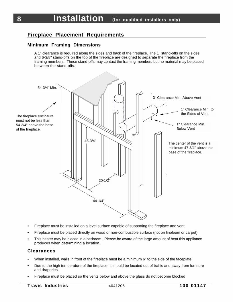
Fireplace Placement Requirements
Minimum Framing Dimensions
A 1" clearance is required along the sides and back of the fireplace. The 1" stand-offs on the sidesand 6-3/8" stand-offs on the top of the fireplace are designed to separate the fireplace from theframing members. These stand-offs may contact the framing members but no material may be placedbetween the stand-offs.
54-3/4" Min.
AAAA
AAAAAAAAAAAAAAAAAAAAAAAA
AAAAAAAAAAAA
AAAA
AAAAAAAAAAAAAAA
AAAAAAAAAAAAAAAAAA
44-1/4"
20-1/2"
46-3/4"
3" Clearance Min. Above Vent
The center of the vent is a minimum 47-3/4" above the base of the fireplace.
1" Clearance Min. to the Sides of Vent
The fireplace enclosure must not be less than 54-3/4" above the base of the fireplace.
1" Clearance Min. Below Vent
• Fireplace must be installed on a level surface capable of supporting the fireplace and vent
• Fireplace must be placed directly on wood or non-combustible surface (not on linoleum or carpet)
• This heater may be placed in a bedroom. Please be aware of the large amount of heat this applianceproduces when determining a location.
Clearances
• When installed, walls in front of the fireplace must be a minimum 6" to the side of the faceplate.
• Due to the high temperature of the fireplace, it should be located out of traffic and away from furnitureand draperies.
• Fireplace must be placed so the vents below and above the glass do not become blocked

Installation (for qualified installers only) 9
Travis Industries 4041206 100-01147
Corner Installations
A typical 45° installationuses the minimum framingdimensions shown in theillustration to the right(NOTE: all clearances stillapply).
AAAAAA
AAAAAA
AAAAAAAAAAAAAAAAAAAAAA
19-3/8"1" Standoffs
Min. 1" Clearance to Fireplace Enclosure
47-5/8"
13-3/4"14-3/4"
Raised Fireplaces
• The fireplace (and hearth, if desired) may be placed on a platform designed to support the fireplace(250 Lbs.) and vent.
• The fireplace may not be raised so as to place the ceiling within 36" of the base of the fireplace.
Raised fireplaceRaised fireplace with raised hearth.
Raised Platform
Nail the nail down plates to the floor (or raised platform)
Raised Hearth
Hearth
Raised Platform

10 Installation (for qualified installers only)
Travis Industries 4041206 100-01147
Hearth Requirements
Min. 3/4”Max. 15/16”
6-1/4"
AAAAAAAAAAAAAAAAAAAAAAAAAAAAAAAAAAAAAAAAAAAAAAAAAAAAAAAAAAAAAAAAAAAAAAAAAAAAAAAAAAAAAAAAAAAAAAAAAAAAAAAAAAAAAAAAAAAAAAAAAAAAAAAAAAAAAAAA
AAAAAAAAAAAAAAAAAAAAAAAAAAAAAAAAAAAAAAAAAAAAAAAAAAAAAAAAAAAAAAAAAAAAAAAAAAAAAAAAAAAAAAAAAAAAAAAAAAAAAAAAAAAAAAAAAAAAAAAAAAAAAAAAAAAAAAAAAAAAAAAAAAAAAAAAAAAAAAAAAAAAAAAAAA
Do not build the hearth
above this ledge.
12” Min.
Cement Board
Tile, Marble, Brick, or other
Non-Combustible
Decorative Trim (may be combustible)
Floor Mounted Fireplaces
Raised Fireplaces
AAAAAAAAAAAAAAAAAAAAAAAAAAAAAAAAAAAAAAAAAAAAAAAAAAAAAAAAAAAAAAAAAAAAAAAAAAAAAAAAAAAAAAAAAAAAAAAAAAAAAAAAAAAAAAAAAAAAAAAAAAAAAAAAAAAAAAAAAAAAAAAAAAAAAAAAAAAAAAAAAAAAAAAAAAAAAAAAAAAAAAAAAAAAAAAAAAAAAAAAAAAAAAAAAAAAAAAAAAAAAAAAAAAAAAAAAAAAAAAAAAAAAAAAAAAAAAAAAAAAAAAAAAAAAAAAA
AAAAAAAAAAAAAAAAAAAAAAAAAAAAAAAAAAAAAAAAAAAAAAAAAAAAAAAAAAAAAAAAAAAAAAAAAAAAAAAAAAAAAAAAAAAAAAAAAA
AAAAAAAAAAAAAAAAAAAAAAAAAAAAAAAAAAAAAAAAAAAAAAAAAAAAAAAAAAAAAAAAAAAAAAAAAAAAAAAAAAAAAAAAAAAAAAAAAAAAAAAAAAAAAAAAAAAAAAAAAAAAAAAAAAAAAAAAAAAAAAAAAAAAAAAAAAAAAAAA
AAAAAAAAAAAAAAAAAAAAAAAAAAAAAAAAAAAAAAAAAAAAAAAAAAAAAAAAAAAAAAAAAAAAAAAAAAAAAAAAAAAA
AAAAAAAAAAAAAAAAAAAAAAAAAAAAAAAAAAAAAAAAAAAAAAAAAAAAAAAAAAAAAAAAAAAAAAAAAAAAAAAAAAAAAAAAAAAAAAAAAAAAAAAAAAAAAAAAAAAAAAAAAAAAAAAAAAAAAAAAAAAAAAAAAAAAAAAAAAAAAAAAAAAAAAAAAAAAAAAAAAAAAAAAAAA
AAAAAAAAAAAAAAAAAAAAAAAA
When raised a minimum of
3” off of the floor surface,
no hearth is required.
AAAAAAAAAAAAAAAAAAAAAAAAAAAAAA
Fireplace Stand
6-1/4"
Min. Hearth WidthThe hearth must be as wide as the face (see page 13 for face dimensions)
Make sure to accomodate the floor covering (carpet, linoleum,
flooring, etc.) when determining the height of the fireplace stand (i.e.
the thicker the carpet, the taller the fireplace stand).
Installation (for qualified installers only) 11
Travis Industries 4041206 100-01147
Facing RequirementsNOTE: The combustible area above the facing must not protrude more than 3/4" from the facing. If it
does, it is considered a mantel and must meet the mantel requirements listed in this manual.
Adhesive
WARNING : Do not use adhesive to secure the cement board or facing. The hightemperatures of the fireplace may cause adhesives to emit odors. Use mastic or thin set (orother non-combustible, non-odorous adherent) to attach the facing to the cement board.NOTE: Screws may be used to secure the cement board to the fireplace. Do not penetratethe fireplace more than 3/4”
AAAAAAAAAAAAAAAAAAAAAAAAAAAAAAAAAAA
6" Min.(both sides)
Non-combustible Facing
AAAAAAAAAAAAAAAAAAAAAAAAAAAAAAAAAAAAAAAAAAAAAAAAAAAAAAAAAAAAAAAAAAAAAAAAAAAAAAAAAAAAAAAAAAAAAAAAAAAAAAAAAAAAAAAAAAAAAAAAAAAAAAAAAAAA
The fireplace requires a concrete board (or other non-combustible) extending from the header to the floor and to the framing members on both sides. Do not use sheetrock, plywood or other combustible material.
Arch FaceRectangular Face
Header
Bottom of Faceplate
SEE PAGE 13 FOR
FACE DIMENSIONS
1"
Base of Fireplace
Combustible Facing
AAAAAAAAAA
Non-Combustible Facing
Top Facing Clearance (see the
table below)
Top Facing Clearance:
• Measured From Top of Faceplate (see “Faceplate Dimensions” on page 13)
8" Max. Mantel Depth 10" Max. Mantel Depth 12" Max. Mantel DepthAvalon Cambridge 12" 12" 12"Avalon Craftsman 12" 12" 12"Avalon Rosario 16" 18" 19"Avalon Victorian Lace 15" 15" 15"Avalon Victorian Lace with shield 12" 12" 12"Avalon Rawhide 15" 15" 15"Avalon Rawhide with shield 12" 12" 12"Avalon Bungalow 18” 18” 18”FPX 34 Arch & Artisan 18" 18.5" 19"FPX 34 Arch & Artisan with shield 13.5" 14" 14.5"FPX Metropolitan 19.5" 19.5" 19.5"FPX Metropolitan with shield 15" 15" 15"FPX Art Deco 19.5" 19.5" 19.5"FPX Art Deco with shield 12" 12" 12"FPX Neo-Classic 17.5" 17.5" 17.5"FPX Neo-Classic with shield 12" 12" 12"FPX Arts & Crafts 19" 19" 19"FPX Arts & Crafts with shield 12" 12" 12"FPX French Country 15.5" 15.5" 15.5"FPX French Country with shield 12" 12" 12"Lopi Discovery 13" 13" 13"Lopi Wilmington 17” 17” 17”

12 Installation (for qualified installers only)
Travis Industries 4041206 100-01147
Facing Over 1" Thick
WARNING :Faces that attach with latch-hooks(Avalon Rosario, Avalon Cambridge,Avalon Salish Bay, Avalon Rawhide,Lopi Discovery, Lopi Heritage Bay, FPXArchitectural Faces (all styles),require a 5/8” gap above thef a c e for face installation and removal.
• If the facing material is over 1" thick(e.g. brick, river rock), install the facingaround the perimeter of the face. Youmay wish to make a facing support (seethe illustration to the right). If using anarch face, you may wish to order theoptional set-up face:
34 Arch Set-Up Face is available fromTravis Industries (Part # 98500694)
• Artisan faces vary in size. Use the facebeing installed to create a template.
AAAAAAAAAAAAAAAAAAAAAAAAAAAAAAAAAAAAAAAAAAAAAAAAAAAAAAAAAAAAAAAAAAAAAAAAAAAAA
AAAA
AAAAAAAAAAAAAAAAAAAAAAAAAAAAAAAAAAAAAAAAAAAAAAAAAAAAAAAAAAAAAAAAAAAAAAAAAAAAAAAAAAAAAAAA
AAAAAAAAAAAAAAAAAAAAAAAAAAAAAAAAAAAAAAAAAAAAAAAAAAAAAAAAAAAAAAAAAAAAAAAAAAAAA
AAAAAAAAAAAAAAAAAAAAAAAAAAAAAAAAAAAAAAAAAAAAAAAAAAAAAAAAAAAAAAAAAAAAAAAAAAAAAAAAAAAAAAAAAAAAAAAAAAAAAAAAAAAAAAAAAAAAAAAAAAAAAAAAAAAAAAAAAAAAAAAAAAAAAAAAAAAAAAAA
AAAA
AAAAAAAAAAAAAAAA
AAAAAAAAAAAAAAAAAAAAAAAA
AAAAAAAAAAAAAAAAAAAAAAAA
AAAAAAAAAAAAAAAAAAAAAAAA
Rectangular FacesMake a facing support using 2x4’s. It should be 1/8” larger than the finished face. NOTE: The bottom of the face is 1” above the base of the fireplace.
1”
Note: if using a brick hearth, the fireplace will need to be raised to accommodate the 1” gap betwen the face and the base of the fireplace. For 2-1/2” thick brick this works out to approximately 1-1/2”.
AAAAAAAAAAAAAAAAAAAAAAAAAAAAAAAAAAAAAAAAAAAAAAAAAAAAAAAAAAAAAAAAAAAAAAAAAAAAAAAAAAAAAAAA
AAAAAAAAAAAAAAAAAAAAAAAAAAAAAAAAAAAAAAAAAAAAAAAAAAAAAAAAAAAAAAAAAAAAAAAAAAAAAAAAAAAAAAAAAAAAAAAAAAAAAAAA
AAAAAAAAA
The brick facing must meet the same requirements listed in “Facing Requirements”
AAAAAAAAAAAAAAAAAAAAAAAA
Center Line
AAAAAAAA
Arch FacesUse the optional Arch Set-Up Face available from Travis Industries.
Facing Detail
Access Door
AAAAAAAAAAAAAAAAAAAAAAAAAAAAAAAA
1"
Face 1"
Glass
Air Space
AAAAAAAAAAAAAAAAAAAAAAAAA
Do not tuck facing under the faceplate on the bottom The 3/8"
(approx.) gap below the access door is required for the door to open. You
may tuck facing under the sides and top, but not on the bottom.
SIDE OVERLAP: To calculate the side overlap,
subtract 32-7/8" from the face (see "Face
Dimensions" on page 13) width and divide by 2.
TOP OVERLAP: To calculate the top overlap,
subtract 25-3/8 from the face height (see "Face
Dimensions" on page 13) - for arched faces, see
the "Dimensions" on page 6 for other details.
AAAAApprox.
3/8"
• To achieve a facing that is flush with the drywall to the side of the fireplace, recess the framing directlynext to the fireplace. See the illustration below.
Fireplace
1"
1/2" Drywall
AAAAAAAAA
1/2" Concrete Board3/8" Tile
This 2x4 is recessed 3/8" to make a flush facing
Fireplace1/2" Drywall
AAAAAAA
1/2" Concrete Board
3/8" TileThe tile overlaps the drywall for an overlap facingFaceplate
1"
TOP VIEW
Faceplate

Installation (for qualified installers only) 13
Travis Industries 4041206 100-01147
Face Dimensions
Face Height Width Notes
Rawhide 27” 35-3/4”
Victorian 27” 35-3/4”
Rosario 26” 35-3/4”
Cambridge 25-7/8” 37-5/8”
Craftsman 27-1/2” 36”
Bungalow 27” 32-3/4”
Classic Arched, Artisan 26-1/2” 34-3/4” Side begins arch 3-1/2” below top - 45” radius
Metropolitan 26-1/2” 34-3/4”
Architectural Series 27-7/8” 33-5/8”
Discovery 26’ 35-3/4’
Wilmington 27” 36-1/8”

14 Installation (for qualified installers only)
Travis Industries 4041206 100-01147
Modifying the Face Angle for Rectangular Faces
If using a rectangular face, adjust the face angles at the top corners of the glass (see the illustrationbelow).
AAAAAAA
AAAAA
Remove these four screws from the face angle.
Phillips Screwdriver
Bend the face angle up and replace the two screws on the upper section.
AAAAAA
AAAAA
AAAAAA
AAAAA
Re-bend the face angle at the inward location and re-attach the lower portion with one screw.
AAAAAAA
AAAAA
Straighten the face angle.
ba
dc
Front of Fireplace
Glass

Installation (for qualified installers only) 15
Travis Industries 4041206 100-01147
Facing and Hearth Examples
AAAAAAAA
AAAAAAAAAAAAAAAAA
AAAAAAAAAAAAAAAAAAAAAAAAAA
Fireplace
Face
3/8" Thick Tile
1/2" Cement Board
Wood Sub Floor
1"
Side View
AAAAAAAAAAAAAAAAAAAAAA
2x4 and Plywood Platform
Face
Side of Fireplace
AAAAAAAAAAAAAAAAAA
AAAAAAAAAAAAAAAAAAAAAAAAA
AAAAAAAAAAAAAAAAAAAAAAAAAAAAAAAAAAAAAAAAAA
Note how the tile facing fits behind the face on the side and top and butts up to the face on the bottom.
When fully installed, there will be approx. 3/8" air space below the access door on the face. Do not block this space (it is required for access door opening and air flow).
Three-Dimensional View
Tile
Cement Board
2x4 and Plywood Platform
If using a hearth, make your platform height a dimension that will accommodate the size tiles you are using and the 1" between the base of the fireplace and the bottom of the face.
SUGGESTION:
Base of Fireplace
Base of Fireplace
1/2" Cement Board & 3/8" Tile (tucked behind the face)
NOTE:Access Door

16 Installation (for qualified installers only)
Travis Industries 4041206 100-01147
Facing and Hearth Examples (continued)
AAAAAAAAAAAAAAAAAAAAAAAAAA
FireplaceFace
3/8" Thick Tile
1/2" Cement Board
Wood Sub Floor
1"
AAAAAAA
1/2" Cement Board & 3/8" thick tile(tucked behind the face)
Side View
Three-Dimensional View
Face
Side of Fireplace
Note how the tile facing fits behind the face on the side and top.
When hearth installation is correctly completed, there will be approx. 3/8" air space below the access door on the face. Do not block this air space (it is required for access door opening and proper air flow).
3/8" Tile
1/2" Cement Board
WARNING:
AAAAAAAAAAAAAAAAAAAAAAAA
AAAAAAAAAAAAAAAAAAAAAAAAAAAAAAAAAAAAAAAA
AAAAAAAAAAAA
AAAAAAAAAAAA
Base of Fireplace
Base of Fireplace
Wood Sub Floor
Do not install cement board underneath the fireplace. To do so would leave a large gap underneath the finish faceplate sides.
NOTE:
Access Door
Installation (for qualified installers only) 17
Travis Industries 4041206 100-01147
Mantel Requirements
• The combustible area above the facing must not protrude more than 3/4" from the facing. If it does, itis considered a mantel and must meet the mantel requirements listed in this manual.
Combustible or Non-Combustible Mantels
Combustible or Non-Combustible MantelMantel Depth
Base of Fireplace1”
Bottom of Faceplate
Face Height
(see “Face Dimensions” on page 13)
Face
Mantel
Clearance
(see table
below)
Mantel Clearance:
• Measured From Top of Faceplate (see “Faceplate Dimensions” on page 13)
8" Max. Mantel Depth 10" Max. Mantel Depth 12" Max. Mantel DepthAvalon Cambridge 15" 15" 15"Avalon Craftsman 15" 15" 15"Avalon Rosario 18" 20" 21"Avalon Victorian Lace 16" 16" 16"Avalon Victorian Lace with shield 16" 16" 16"Avalon Rawhide 16" 16" 16"Avalon Rawhide with shield 16" 16" 16"Avalon Bungalow 26” 26” 26”FPX 34 Arch & Artisan 24" 25" 26"FPX 34 Arch & Artisan with shield 17.5" 18" 18.5"FPX Metropolitan 24" 24" 24"FPX Metropolitan with shield 16.5" 16.5" 16.5"FPX Art Deco 19.5" 19.5" 19.5"FPX Art Deco with shield 15" 15" 15"FPX Neo-Classic 19" 19" 19"FPX Neo-Classic with shield 15" 15" 15"FPX Arts & Crafts 20" 20" 20"FPX Arts & Crafts with shield 15" 15" 15"FPX French Country 16" 18" 19"FPX French Country with shield 15" 15" 15"Lopi Discovery 16" 16" 16"Lopi Wilmington 19” 19” 19”
18 Installation (for qualified installers only)
Travis Industries 4041206 100-01147
Vent Requirements
• The vent must maintain the required clearance to combustible materials to prevent a fire (see“Clearances” below). Do not fill air spaces with insulation.
• The gas appliance and vent system must be vented directly to the outside of the building, and neverbe attached to a chimney serving a separate solid fuel or gas-burning appliance. Each direct vent gasappliance must use it's own separate vent system.
Altitude Considerations
This heater has been tested at altitudes ranging from sea level to 8,000 feet (2,400 M). In this testing we havefound that the heater, with its standard orifice, burns correctly with just an air shutter adjustment.
• Failure to adjust the air shutter properly may lead to improper combustion which can create a safety hazard.Consult your dealer or installer if you suspect an improperly adjusted air shutter.
Vent Clearances
Horizontal Runs
AAAAAA
Vertical Sections
Min. 3" Clearance Above 45° Sloping Vent
AAAAAAAAAAAA
Min. 1" Clearance to the Sides of the Vent
AAAAAAAAAAAA
AAAAAAAAA
AAA
The included firestop (Travis part # 93006094) is required when passing through any wall.
Min. 3" Clearance Above the Vent
AAAAAAAAAAA
AAAAAAAAA
Min. 1" Clearance to the Sides
AA
Firestop
Min. 1" Clearance Below the Vent
Min. 1" Clearance Below the Vent
Approved Vent Components for Top Vent Configuration
• Use 8” diameter Model GS Direct Vent manufactured by Simpson Dura-Vent only . Follow theinstallation instructions included with the vent. For the nearest Simpson Dura-Vent supplier, call (800)835-4429. Vent part numbers and descriptions are listed below.
Straight Lengths1208B 6" Pipe Length, Black1207B 9" Pipe Length, Black1206B 12" Pipe Length, Black1204B 24" Pipe Length, Black1203B 36" Pipe Length, Black1202B 48" Pipe Length, Black1211B 11” to 14-5/8" Adjustable, Black
Firestops & Support93006094 Travis Hor. Firestop (44 DV XXL or DVL FP EF)1263 Ceiling Firestop1288 Wall Strap
Terminations1284 Horizontal Square Termination1285 Hor. High Wind Termination1250 Vinyl Siding Stand-off1291 Travis Vertical Termination
Elbows1245B 45° Elbow, Black1290B 90° Elbow, Black

Installation (for qualified installers only) 19
Travis Industries 4041206 100-01147
Vent Installation
• In addition to the requirements below, follow the requirements provided with the vent.
Vertical Termination (part # 1291)
Use a roof flashing and storm collar whenever passing through the roof
Vertical Vent Requirements
Horizontal Vent Requirements
Min. 1" Clearance on Vertical Sections to combustible surfaces.
Use a firestop whenever passing through a ceiling (or enclosure and at every floor penetration.
Combustible Framing
Use the Travis Firestop (part # 93006094) when passing through a wall. NOTE: make sure the firestop is postitioned correctly so the 3" clearance is allowed above the vent.
3" Min.
1" Min.
1" Min.Combustible Surfaces
• Slide the vent sections together and turn 1/4 turn until the sections lock inplace.
• Screws are not required to secure the vent. However, three screws may beused to secure vent sections together if desired.
• High temperature sealant is recommended at the appliance starter sectionconnection (use high-temperature silicone or Mill-Pac®).
• If disassembly is required, at time of re-assembly check to see if the ventcreates a tight fit. If it does not, apply high temperature sealant to the joints ofthe affected sections.
• Horizontal sections require a 1/4" rise every 12" of travel
• Horizontal sections require non-combustible support every three feet (e.g.: plumbing tape)
20 Installation (for qualified installers only)
Travis Industries 4041206 100-01147
Approved Vent Configurations
Restrictor Position
Remove the face (if installed).
To Adjust the Restrictor:
To Access the Restrictor:
1
2
Determine the correct restrictor position (see the charts under "Approved Vent Configurations" - the factory position is #1).Lift up the adjustment plate and move it so the correct notch falls into the slot on the adjustment bracket.
This restrictor is in position 1 (factory setting).
This restrictor is in position 4 - To adjust, lift the adjustment plate
and push it back.
WARNING: Use a glove to protect your hand from burns.
Adjustment Bracket
Adjustment Plate
# 8# 7
# 2etc.
NOTE: position 5 is fully closed - positions 6 through 8 are not used.
MeasuringVentLengths
NOTE:All measurements are for 8" diameter vent.
Vent Horizontal
Run
Vent Height
3-1/2"
Side View
1-3/4"Vent Length(2', 3', etc.)
NOTE:Vent sections overlap each other by 1-3/4"
42"
10-3/4" wide with 1-3/4" to
3-3/8" of overlap
Starter Section
12-3/8"
3-1/2"
8"

Installation (for qualified installers only) 21
Travis Industries 4041206 100-01147
Vertical Terminations with 0, 2, or 4 45° Offsets
• Use 8” diameter co-axial vent
• A Maximum of Four 45° Elbows May be Used
• 8’ Minimum System Height (without offsets)
• 44’ Maximum System Height
• 12’ Maximum Horizontal Offset (6’ 6” for 4 Offsets)
Offset Length Hor. Offset Vert. RiseNone 5" 1'1' Section 1' 1' 7"2' Section 1' 9" 2' 4"3' Section 2' 5" 3'4' Section 3' 2" 3' 8"
Offset Length
Horizontal Offset
Vertical Rise
• The termination must fall within the shaded area shown in the chart. Use the indicated restrictor position.
AAAAAAAAAAAAAAAAAAAAAAAAAAAAAAAAAAAAAAAAAAAAAAAAAAAAAAAAAAAAAAAAAAAAAAAAAAAAAAAAAAAAAAAAAAAAAAAAAAAAAAAAAAAAAAAAAAAAAAAAAAAAAAAAAAAAAAAAAAAAAAAAAAAAAAAAAAAAAAAAAAAAAAAAAAAAAAAAAAAAAAAAAAAAAAAAAAAAAAAAAAAAAAAAAAAAAAAAAAAAAAAAAAAAAAAAAAAAAAAAAAAAAAAAAAAAAAAAAAAAAAAAAAAAAA
AAAAAAAAAAAAAAAAAAAAAAAAAAAAAAAAAAAAAAAAAAAAAAAAAAAAAAAAAAAAAAAAAAAAAAAAAAAAAAAAAAAAAAAAAAAAAAAAAAAAAAAAAAAAAAAAAAAAAAAAAAAAAAAAAAAAAAAAAAAAAAAAAAAAAA
5 feet
10 feet(min.)
15 feet
20 feet
25 feet
30 feet
0 feet
35 feet
0 fe
et
5 fe
et
6' 6
" (m
ax)
5 feet
0 feet
0 fe
et
5 fe
et
6' 6
" (m
ax)
10 feet(min.)
15 feet
20 feet
25 feet
30 feet
35 feet
Four 45° Offsets
5 feet
10 feet
15 feet
20 feet
25 feet
30 feet
0 feet
40 feet
0 fe
et
5 fe
et
5 feet
0 feet
0 fe
et
10 feet
15 feet
20 feet
30 feet
Zero or Two 45° Offsets
5 fe
et 12'
(max
)
25 feet
10 fe
et
12'
(max
)
10 fe
et
Restrictor Position # 5
35 feet 35 feet
40 feet 40 feet 40 feet
Restrictor Position # 5
44' (max) 44' (max)44' (max) 44' (max)

22 Installation (for qualified installers only)
Travis Industries 4041206 100-01147
Vertical Terminations with 2 90° Elbows
The termination must fall within the shaded area shown in the chart. Use the indicated restrictor position.
AAAAAAAAAAAAAAAAAAAAAAAAAAAAAAAAAAAAAAAAAAAAAAAAAAAAAAAAAAAAAAAAAAAAAAAAAAAAAAAAAAAAAAAAAAAAAAAAAAAAAAAAAAAAAAAAAAAAAAAAAAAAAAAAAAAAAAAAAAAAAAAAAAAAAAAAAAAAAAAAAAAAAAAAAAAAAAAAAAAAAAAAAAAAAAAAAAAAAAAAAAAAAAAAAAAAAAAAAAAAAAAAAAAAAAAAAAAAAAAAAAAAAAAAAAAAAAAAAAAAAAAAAAAAAAAAAAAAAAAAAAAAAAAAAAAAAAAAAAAAAAAAAAAAAAAAAAAAAAAAAAAAAAAAAAAAAAAAAAAAAAAAAAAAAAAAAAAAAAAAAAAAAAAAAAAAAAAAAAAAAAAAAAAAAAAAAAAAAAAAAAAAAAAAAAAAAAAAAAAAAAAAAAAAAAAAAAAAAAAAAAAAAAAAAAAAAAAAAAAAAAAAAAAAAAAAAAAAAAAAAAAAAAAAAAAAAAAAAAAAAAAAAAAAAAAAA
5 feet
10 feet(min.)
15 feet
20 feet
25 feet
30 feet
0 feet
44' (max)
5 fe
et
10 fe
et
15 fe
et
0 fe
et
5 fe
et
10 fe
et
15 fe
et
24'(m
ax)
15 feet
20 feet
25 feet
30 feet
0 feet
0 fe
et
NOTE: Horizontal sections require a 1/4" rise every 12" of travel.
10 feet(min.)
44' (max)
24'(m
ax)
Restrictor Position # 5
5 feet
NOTE: One 45° or 90° elbow may be used between horizontal sections. Horizontal length is calculated by adding each horizontal run together.
35 feet35 feet
20 fe
et20
feet
40 feet40 feet

Installation (for qualified installers only) 23
Travis Industries 4041206 100-01147
Horizontal Terminations with 1 Vertical Elbow
The termination must fall within the shaded area shown in the chart. Use the indicated restrictor position.
NOTE:
• One horizontal elbow (45° or 90°) is allowed. The
horizontal vent length is calculated by adding the length
before and after the elbow (H1 + H2 = horizontal vent
length).
• Horizontal sections require a 1/4" rise every 12" of travel.
• The maximum vertical height is 20'.
• The maximum horizontal length is 24'.
H1
Horizontal Elbow (45° or 90°)
Vertical Elbow
H2
AAAAAAAAAAAAAAAAAAAAAAAAAAAAAAAAAAAAAAAAAAAAAAAAAAAAAAAAAAAAAAAAAAAAAAAAAAAAAAAAAAAAAAAAAAAAAAAAAAAAAAAAAAAAAAAAAAAAAAAAAAAAAAAAAAAAAAAAAAAAAAAAAAAAAAAAAAAAAAAAAAAAAAAAAAAAAAAAAAAAAAAAAAAAAAAAAAAAAA
AAAAAAAAAAAAAAAAAAAAAAAAAAAAAAAAAAAAAAAAAAAAAAAAAAAAAAAAAAAAAAAAAAAAAAAAAAAAAAAAAAAAAAAAAAAAAAAAAAAAAAAAAAAAAAAAAAAAAAAAAAAAAAAAAAAAAAAAAAAAAAAAAAAAAAAAAAAAAAAAAAAAAAAAAAAAAAAAAAAAAAAAAAAAAAAAAAAAAAAAAAAAAAAAAAAAAAAAAAAAAAAAAAAAAAAAAA
AAAAAAAAAAAAAAAAAAAAAAAAAAAAAAAAAAAAAAAAAAAAAAAAAAAAAAAAAAAAAAAAAAAAAAAAAAAAAAAAAAAAAAAAAAAAAAAAAAAA
5 feet
0 feet
0 fe
et
5 feet
0 fe
et
20' (max) 20' (max)
5 fe
et
10 fe
et
5 fe
et
10 fe
et
0 feet
15 fe
et
24' (
max
)
10 feet
15 feet
15 fe
et
24' (
max
)
10 feet
15 feet
Restrictor Position #1
Restrictor Position #2
Restrictor Position #4
Restrictor Position #5
20 fe
et20
feet

24 Installation (for qualified installers only)
Travis Industries 4041206 100-01147
Horizontal Terminations with 3 Vertical Elbows
The termination must fall within the shaded area shown in the chart. Use the indicated restrictor position.
AAAAAAAAAAAAAAAAAAAAAAAAAAAAAAAAAAAAAAAAAAAAAAAAAAAAAAAAAAAAAAAAAAAAAAAAAAAAAAAAAAAAAAAAAAAAAAAAAAAAAAAAAAAAAAAAAAAAAAAAAAAAAAAAAAAAAAAAAAAAAAAAAAAAAAAAAAAAAAAAAAAAAAAAAAAAAAAAAAAAAAAAAAAAAAAAAAAAAAAAAAAA
AAAAAAAAAAAAAAAAAAAAAAAAAAAAAAAAAAAAAAAAAAAAAAAAAAAAAAAAAAAAAAAAAAAAAAAAAAAAAAAAAAAAAAAAAAAAAAAAAAAAAAAAAAAAAAAAAAAAAAAAAAAAAAAAAAAAAAAAAAAAAAAAAAAAAAAAAAAAAAAAAAAAAAAAAAAAAAAAAAAAAAAAAAAAAAAAAAAAAAAAAAAA
AAAAAAAAAAAAAAAAAAAAAAAAAAAAAAAAAAAAAAAAAAAAAAAAAAAAAAAAAAAAAAAAAAAAAAAAAAAAAAAAAAAAAAAAAAAAAAAAAAAAAAAAAAAAAAAAAAAAAAAA
NOTE:
• A total of three elbows must be used.
• No horizontal elbows may be used (a horizontal elbow is
defined as an elbow that directs the vent from a horizontal
direction to another horizontal direction).
• Two 45° elbows may be substituted for two of the 90° elbows.
• Horizontal sections require a 1/4" rise every 12" of travel.
• The maximum vertical height is 19'.
• The maximum horizontal length is 20'.
Horizontal Elbows are NOT ALLOWED
5 feet
0 feet
0 fe
et
5 feet
0 fe
et
19' (max) 19' (max)
5 fe
et
10 fe
et
5 fe
et
10 fe
et
0 feet
15 fe
et
20' (
max
)
10 feet
15 feet
15 fe
et
20' (
max
)
10 feet
15 feet
Restrictor Position #1
Restrictor Position #2
Restrictor Position #4
Restrictor Position #5

Installation (for qualified installers only) 25
Travis Industries 4041206 100-01147
Termination Requirements (see the illustration below)
! Venting terminals shall not be recessed into a wall or siding.
A Minimum 9" clearance from any door or window
B Minimum 12" above any grade, veranda, porch, deck or balcony
C Minimum 3" from outside corner walls
D Minimum 12" from inside corner walls
E Minimum 11" clearance below unventilated soffits or roof surfacesMinimum 18" clearance below ventilated soffitsMinimum 6" clearance from roof eavesNOTE: Vinyl surfaces require 24"
11” Min.
6” Min.
Roof Surface
Roof Eaves
F Minimum 18" clearance below a veranda, porch, deck or balcony (must have two open sides)
G Minimum 48" clearance from any adjacent building
H Minimum 84" clearance above any grade when adjacent to public walkways or drivewaysNOTE: may not be used over a walkway or driveway shared by an adjacent building
I Minimum 48" clearance from any mechanical air supply inlet
J Minimum 36" clearance above and 48” below and to the sides of non-mechanical air supply inlet
K Minimum 36" from the area above the gas meter/regulator (vent outlet)
L Minimum 36" from the gas meter/regulator (vent outlet)
M Minimum 12” above the roof line (for vertical terminations)
N Minimum 24” horizontal clearance to any surface (such as an exterior wall) – for vertical terminations
C
B
H
E
G A
DF
L
K J
I
NOTE: Measure clearances to the nearest edge of the exhaust hood.
AE
E
M
N
• Use the vinyl siding standoff when installing on an exterior with vinyl siding.
• Vent termination must not be located where it will become plugged by snow or other material
• These clearances meet UMC-1994 code standards.

26 Installation (for qualified installers only)
Travis Industries 4041206 100-01147
Gas Line Requirements
• The gas line must be installed in accordance with all local codes, if any; if not, follow ANSI 223.1 andthe requirements listed below.
• The fireplace and gas control valve must be disconnected from the gas supply piping during anypressure testing of that system at test pressures in excess of 1/2 psig. For pressures under 1/2 psig,isolate the gas supply piping by closing the manual shutoff valve.
• Leak test all gas line joints and the gas control valve prior to and after starting the fireplace.
Fuel
• This fireplace is designed either for natural gas or for propane (but not for both). Check the sticker onthe top of the gas control valve to make sure the correct fuel is used.
Gas Line Connection
• A manual shutoff valve is required within for installation (within 3’ of the heater). T-Handle gas cocksare required in Massachusetts in compliance with code 248CMR.
• Installation must be performed by a qualified installer, service agency or the gas supplier (InMassachusetts a licensed plumber/gasfitter).
Gas Control Valve
3/8" M.P.T to 1/2" O.D. Fitting (Factory installed)
The 1" diameter access hole is located 2-5/8" above the base of the fireplace. Cut an "X" in the gasket covering the inlet and insert the gas line through the gasket.
If the gas line is routed from the right side, bend the flex tube 180°.
10" Flex Tube (shipped with the fireplace - min. bending radius is 3/4")
A shutoff valve may be placed within the fireplace
The included fitting accepts a 3/8" M.P.T. or
1/2" F.P.T.
-- OR --
-- OR --
6-5/8"
18-1/8"
5"
Gas Inlet Pressure: Standard Input Pressure
Natural Gas 7" W.C. (1.74 kPA)
Propane 13" W.C. (2.73 kPA)
• If the pressure is not sufficient, make sure the piping used is large enough, the supply regulator isadequately adjusted, and the total gas load for the residence does not exceed the amount supplied.
• The supply regulator (the regulator that attaches directly to the residence inlet or to the propane tank)should supply gas at the suggested input pressure listed above. Contact the local gas supplier if theregulator is at an improper pressure.

Installation (for qualified installers only) 27
Travis Industries 4041206 100-01147
Electrical Connection
• Make sure the household breaker is shut off prior to working on any electrical lines.
• The fireplace must be properly grounded in accordance with local codes (or ANSI/NFPA 70-1987)
• The electrical line must be 14 gauge, and supply 120 Volts at 60 Hz (2 Amps)
• Follow the directions below to connect power to the fireplace.
a bInsert the sheathed cable from the power source through this cable clamp. Once the wires are attached, tighten the clamp to secure the cable.
Replace the cover removed in step "a".
Attach the common (white), ground (exposed or green) wires, and hot (black) wires from the power source to the electrical connector (attached to the fireplace).
c
dStandard Screwdriver
Remove the cover from the fireplace junction box.
1/4"
Nut
driv
er
Electrical Connector
WARNING: Make sure power is off from the power lead before conducting any wiring.

28 Finalizing the Installation
Travis Industries 4041206 100-01147
1 Remove the glass following the directions below.
Warning: The appliance must be completely cool before removing the glass.
Warning: Do not strike or slam the glass.
Note : If using an Victorian Lace face, attach the arch covers after installing the glass.
Open the four latches holding the glass
frame in place (start with the two below
the glass) - follow the directions shown
to the right.
a
Twist 1/4 turn.
The spring pin will
disengage from the
latch bracket,
opening the latch.
Latch Bracket
Insert the 1/4” key
into the spring
pin.
Glass
Top of Firebox
Spring Pin
Glass Frame
Lift the glass
frame up and
pull it forward to
remove.
b
Re-Attaching the Glass Frame:
a) Hang the glass frame on the firebox.
b) While holding in place, attach the upper latches
(follow the instructions to the right in reverse).
c) Lift the glass frame slightly and attach the lower latches.
NOTE:
You may need to lift the glass
frame while re-attaching.

Finalizing the Installation 29
Travis Industries 4041206 100-01147
Glass Frame Removal and Installation (continued)
The spring pin can come loose from the latch assembly. This occurs when it is turned 1/4 turn when it isdisengaged. Follow the directions below to re-install the spring pin if it becomes loose.
To re-install the spring pin, first
insert this end into a 1/4” key.
Insert the spring pin into
this bracket with the pins
aligned vertically.
Push in slightly and
twist 1/4 turn.
With this pin horizontal, the
spring pin will remain in place.
NOTE: The spring pins
can be installed with the
glass frame in place or
removed.

30 Finalizing the Installation
Travis Industries 4041206 100-01147
• If converting to propane, do so now before installing the logs (page 43).
2 Install the log set following the directions below.
AAAAAA
AAAAAAAAAA
aPlace the rear log on the two platforms at the rear of the firebox.
bPlace the left and right logs. The pins on the burner insert into the holes on the logs.
AAAAAAAAAAAAA
AAAAAAA
AAAAAAAA
AAAAAAAAAAAAAA
AAAAAAAAAAAAAAAA
AAAAAAA
These pins insert into the holes in the log.
cPlace the twig over the rear log. The pins on the log insert into the holes on the twig.
AAAAAAAAAAAAA
AAAAAAA
Place the embers over the front and side edges of the burner (do not place them over the burner holes). Place them in a random pattern.
dOn newer untis, an ember chunk is included with the heater (instead of cast into the burner). Place it in the location shown (it should not cover any burner holes).
e

Finalizing the Installation 31
Travis Industries 4041206 100-01147
3 We recommend you purge the gas line at this time (with the glass removed). This allows gas to bedetected once it enters the firebox, ensuring gas does not build up. Replace the glass.
4 Install the faceplate following directions included with the face.
• ACID WASH WARNING : Before installing the faceplate, make sure any masonry that has beentreated with acid wash has been properly neutralized (this is used primarily with brick faces). Acid wash(muriatic acid) is used to remove excess mortar. If not properly neutralized with an ammonia solution,the gold face may develop a permanent tarnish when the acid evaporates over time. Contact yourdealer if uncertain your facing has been properly neutralized.
5 Turn on the gas to the fireplace. Turn on gas to the heater. Leak test all gas joints prior to starting theappliance. Start the pilot. Start the main burner. Leak test all gas joints again.
6 Check the pilot flame to make sure it looks like the illustration below. Adjust the pilot flame ifnecessary.
Standard Screwdriver
The pilot flame must contact the thermocouple and
thermopile (see the illustration below). Adjust the pilot up or
down as necessary.
To adjust the pilot flame, turn this screw. Clockwise
lowers the flame while counter-clockwise raises it.
7 Let the heater burn for fifteen minutes. Adjust the air shutter, if necessary, to achieve the correctlooking flame (see the illustration below).
• The air shutter adjusts the amount of air that mixes with the gas before it exits the burner holes.
Gas Control Valve
NOTE: If the air shutter is all the way
open, yet the flames remain sooty, shut
off gas to the fireplace and contact a
qualified gas service technician.
CorrectFlames should be blue at the
base, yellow-orange on the top.
If the flames are too tall or sooty on the
ends, open the air shutter.
Not Enough AirIf the flames are all blue and
short, close the air shutter.
Too Much Air
NOTE: The logs must be installed correctly to
monitor the flame while adjusting the air shutter.
Pushing the control to the right gives the
flame less air (closed) - making it more
orange. Pushing to the left gives the flame
more air (open), making it more blue. For
fine adjustments use a screwdriver to tap
the air shutter.
ADJUSTING THE AIR SHUTTERS
Air Shutter Control

32 Finalizing the Installation
Travis Industries 4041206 100-01147
8 Turn the flame adjust knob to its highest position - the flames should not be sooty or come incontinuous contact with the firebox ceiling. Check the flame on low position. The flames should burnoff of each burner hole. If the heater does not work correctly, contact your dealer for a remedy.
FINE TUNING THE EMBER-FYRE™ BURNER
Each installation is affected by altitude, vent configuration, and fuel quality. Because of this, the restrictor and airshutter may need to be fine tuned to each installation. Follow the hints below to fine-tune the burner foroptimum performance and aesthetics.
Restrictor Hints:Set the restrictor to the position suggested in the vent configuration table. Turn the heater on and allow it toreach full temperature (15 min.). If the flames indicate there is excessive draft due to altitude or climate, you maywish to adjust the restrictor to a more restrictive position (higher number). Active, flickering short flames are anindication of excessive draft. If the flames lift off of the burner holes, this indicates not enough draft (restrictor isset too open). After adjustments are made the unit must be cooled down to room temperature and restarted tomake sure that the restriction is not so severe that the pilot will drop out when it is restarted. If the pilot doesdrop out reduce the restriction until it will operate continuously.
Air Shutter Hints:• For more glow, open the air shutter, however, this will make the flames more blue.
• For yellow flames, close the air shutter, however, this may create less glow.
The flames should burn right off the top of the burner ports (if they are too blue, adjust the air control).
Lifting flames indicate insufficient draft (restrictor is set too high).
BurnerBurner Ports
(holes)
Ghosting flames indicate insufficient air (restrictor set too high, air shutter shut down, or other venting error).
Lifting FlamesCorrect Flames
AAAAAAAAA
AAAAAAAA
AAAAAAAAA
AAAAAAAAAAAAAAAAAA
AAAAAAAA
AAAAAAAA
AAAAAAAAA
Ghosting Flames Flickering Flames
Flickering, short flames indicate excessive draft (move air shutter to a higher position).
Warning: If the vent configuration is installed incorrectly the vent may cause the flames inside the heater to lift or“ghost” – a dangerous situation. Inspect the flames after installation to insure proper performance. If thevent configuration is correct, yet the flames are lifting or ghosting, shut off gas to the heater and contactthe dealer for information on remedying the problem.
9 Give this manual to the home owner and fully explain the operation of this heater.

Operation 33
Travis Industries 4041206 100-01147
Before You Begin
• Read this entire manual before you use your new fireplace (especially the section "SafetyPrecautions" on pages 4 & 5). Failure to follow the instructions may result in property damage, bodilyinjury, or even death.
Location of Controls - See explanation below
Gas Control Knob Flame Adjust Knob
Gas Control
ValveAAAAAAAAAAAAAAAAAAAAAAAAAAAAAAAAAAAAAAAAAAAAAAAAAAAAAAAAAAAAAAAAAAAAAA
Swing the control cover down to access the gas control valve, igniter, and blower control.
Blower KnobB
LOW
ER
PILOT IGNITER
Pilot Igniter
ON/OFF Switch
The Pilot Flame can be found below the back log on the left side.
ON
OFFMA
IN B
UR
NE
R
Blower Knob This knob controls the speed of the internal convection blower that pushesthe heated air into the room.
On/Off Switch This control is used to turn the fireplace on and off.
Pilot Igniter The pilot igniter is used only to start the pilot. When pressed, it sends anelectrical charge to the pilot assembly. This creates a blue spark directly nextto the pilot, igniting the pilot flame.
Gas Control Knob This knob is used to control gas to the fireplace and for starting the pilot.There are three positions, ON, OFF, & PILOT. The pointer to the left of theknob indicates the position this knob is in.
Flame Adjust Knob This knob controls the flame height from low ("LO") to high ("HI"). The pointerabove the knob points to the position this knob is in.
34 Operation
Travis Industries 4041206 100-01147
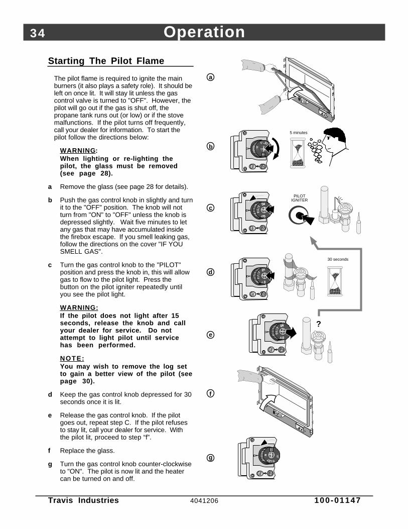
Starting The Pilot Flame
The pilot flame is required to ignite the mainburners (it also plays a safety role). It should beleft on once lit. It will stay lit unless the gascontrol valve is turned to "OFF". However, thepilot will go out if the gas is shut off, thepropane tank runs out (or low) or if the stovemalfunctions. If the pilot turns off frequently,call your dealer for information. To start thepilot follow the directions below:
WARNING :When lighting or re-lighting thepilot, the glass must be removed(see page 28).
a Remove the glass (see page 28 for details).
b Push the gas control knob in slightly and turnit to the "OFF" position. The knob will notturn from "ON" to "OFF" unless the knob isdepressed slightly. Wait five minutes to letany gas that may have accumulated insidethe firebox escape. If you smell leaking gas,follow the directions on the cover "IF YOUSMELL GAS".
c Turn the gas control knob to the "PILOT"position and press the knob in, this will allowgas to flow to the pilot light. Press thebutton on the pilot igniter repeatedly untilyou see the pilot light.
WARNING:If the pilot does not light after 15seconds, release the knob and callyour dealer for service. Do notattempt to light pilot until servicehas been performed.
NOTE:You may wish to remove the log setto gain a better view of the pilot (seepage 30).
d Keep the gas control knob depressed for 30seconds once it is lit.
e Release the gas control knob. If the pilotgoes out, repeat step C. If the pilot refusesto stay lit, call your dealer for service. Withthe pilot lit, proceed to step “f”.
f Replace the glass.
g Turn the gas control knob counter-clockwiseto "ON". The pilot is now lit and the heatercan be turned on and off.
?
AAAAAA
AAAA
30 seconds
PILOT IGNITER
a
b
AAAAAAAAAA
AAAA
5 minutes
c
d
e
f
g

Operation 35
Travis Industries 4041206 100-01147
Starting the Fireplace for the First Time
• Burn the heater at a high setting with the blower off for an extended period (up to 48 hours). This willcure the painted surfaces. Fumes from the paint curing and oil burning off the steel will occur. This isnormal. We recommend opening a window to vent the room.
• Condensation may appear on the glass each time you start the fireplace - this is normal.
• Blue Flames will occur on the fireplace when it first comes on. After fifteen minutes the flames willturn a more realistic yellow and orange color.
• Certain installations use a remote "wall switch" to turn the fireplace on and off. If this is the case, leavethe ON/OFF switch "ON".
Turning the Fireplace On and Off
OFF
ROO
M T
EMP
°F°F
SET TE
MP
TIM
ER
MIN
Tim
eSet
Tim
eCan
cel
Au
to
OFF
ON
Use this switch to turn the main burner on and off manually.
After the pilot has been started...
See the instructions included with the remote for details on operation.
For systems with wall thermostats, use this switch to control the temperature (right is hotter, left cooler). Some systems require the on/off switch to be on.
See the instructions included with the remote for changing the battery.
• Do not place any combustible items on top of or directly in front of the fireplace, even temporarily. Theoptional thermostat may start the fireplace causing a combustible item to ignite.
• If the fireplace turns on and off frequently while using the thermostat, you may want to adjust the flameheight down until it produces just enough heat needed.
Adjusting the Flame Height• Your fireplace has an adjustable flame to tailor the look and heat output to your specific needs. It is
adjusted by turning the middle dial on the gas control valve.
Flame Height Adjustment Knob
Index Mark
Turn counter-clockwise to adjust the flame higher, clockwise to lower.

36 Operation
Travis Industries 4041206 100-01147
Adjusting the Blower Speed
The blower helps transfer heat from the heater into the room. It will not turn on until the heater is up totemperature (approximately 10 minutes after starting). See the illustration below for instructions onadjusting the blower speed.
OFFTurn the dial all the way counter-clockwise until it clicks off.
HIGHThe high position is all the way counter-clockwise, without clicking off.
LOWTurn the dial all the way clockwise.
Normal Operating Sounds
Gas Control ValveAs the gas control valve is turned on and off you will hear a dull clicking sound. This is the valve opening up and shutting down.
Blower Snap Disk This part can produce a clicking sound as it turns the blower on and off.
The appliance will creak with change of temperature.
Pilot FlameThe pilot flame, which remains on, makes a very slight "whisper" sound.
Blower This heater uses a blower to push heated air into the room. You will hear the sound of air movement that increases as the speed is increased.
Extinction Pops It is not unusual, especially on Propane (LP) appliances, to experience a "pop" when the burner is shut off.
Normal Operating Odors
This appliance has several areas that reach high temperatures. Dust or other particles on these areasmay burn and create an odor. This is normal during start-up. You may notice the smell is more acute ifthe appliance was left idle for a long period.

Maintenance 37
Travis Industries 4041206 100-01147
Maintaining Your Fireplace's Appearance
• Fingerprints or other marks left on the optional gold surface may become etched in place if they arenot wiped clean prior to turning the fireplace on. Clean the gold with denatured alcohol and a softcloth (with the fireplace cool). Other cleaners may leave a film that may become etched into the gold.
Yearly Service Procedure
• Failure to inspect and maintain the fireplace may lead to improper combustion and a potentiallydangerous situation. We recommend the following procedures be done by a qualified technician.
1 Check the pilot flame. It should touch approximately 3/8" of the top of the thermopile and touch thetop of the thermocouple (see illustration below). If it does not, contact your dealer for service.
2 Shut off gas to the fireplace by turning the gas control knob to "OFF" (see step A under "Starting thePilot" on page 34). Let the fireplace cool for 15 minutes. Remove the faceplate (see the instructionsincluded with the face) and glass (see page 28).
3 Remove the log set (NOTE: the logs are very fragile - see page 30). If severely deteriorated,replace. Check the logs for sooting. A small amount of soot along the bottom of the logs is normal. Ifexcessive sooting is found, the fireplace will require adjustment. Contact your dealer.
4 Clean the burner (especially the burner holes) and inspect the following:
• Make sure the burner is not warped, cracked, or damaged.• Check the firebox and area around the pilot to make sure there is no warping or damage.
If any problem is found, discontinue use and contact your dealer for service.
AAAA
AAAAAAAA
Check the
burner
holes.
Make sure the burner
is not warped or
damaged.
Check the walls and ceiling of the firebox for
deterioration.
ThermopilePilot Hood
Thermocouple
Before Disassembly - Check
the pilot flame. It should touch
the thermocouple and
thermopile.
5 Replace the log set. Clean and replace the glass (use non-abrasive cleaner - if damaged, replace).Make sure the gasket along the perimeter of the glass contacts the face of the firebox and forms an air-tight seal. If it does not, re-align or replace the gasket to insure an air-tight seal. Replace the faceplate.
6 Inspect behind the access door. Clean if necessary. Check the gas control valve gas lines. If damageis found, discontinue use and contact your dealer for service. Clean the air channels and ducts.
7 Start the pilot and turn on the main burner. The flames should be orange/yellow and not touch the topof the firebox. If the pilot or main burners do not burn correctly, contact your dealer for service.Monitor the blower operation.
8 Remove any debris or vegetation near the vent termination. Contact your dealer if any sooting ordeterioration is found near the vent termination.

38 Maintenance
Travis Industries 4041206 100-01147
Troubleshooting Table
Problem: Possible Cause: Don't Call for ServiceUntil You:
Pilot Will Not Light A gas shut off valve is turned off
The gas control knob isn't turned to "PILOT"
The valve control knob isn't pushed in
The igniter wasn't pressed repeatedly
No Propane in Tank
Check all gas shut off valves
See "Starting the Pilot Light" Step C
See "Starting the Pilot Light" Step C
See "Starting the Pilot Light" Step C
Check Tank Level
Main Burners Will NotStart
The pilot light has gone out
The gas control valve is turned to "PILOT" or "OFF"
The ON/OFF switch is turned to "OFF"
The remote control is not working correctly
The thermostat is disconnected or set too low
See "Starting the Pilot Light"
See "Starting the Pilot Light"
Turn the ON/OFF switch to "ON"
See the remote control instructions
See "Thermostat Operation"
Remote Control DoesNot Work
The pilot light has gone out
The gas control valve is turned to "PILOT" or "OFF"
The ON/OFF switch is turned to "OFF"
The remote is too far away from the fireplace
The remote control receiver is turned "Off"
One of the two remote control batteries is dead
See "Starting the Pilot Light"
See "Starting the Pilot Light"
Turn the ON/OFF switch to "ON"
Use the remote closer to the fireplace
See the remote control instructions
See the remote control instructions
Thermostat Does NotWork
The pilot light has gone out
The gas control valve is turned to "PILOT" or "OFF"
The ON/OFF switch is turned to "OFF"
The thermostat is set too low
See "Starting the Pilot Light"
See "Starting the Pilot Light"
Turn the ON/OFF switch to "ON"
See "Thermostat Operation"
Fireplace Will NotDistribute Heat
The fireplace is not getting electricity
The fireplace is not up to temperature
Check the breaker switch
See "Operating Your Fireplace"
Pilot Goes Out Once AMonth Or More
The gas supply has been shut off Keep the gas supply turned on
Flames Are Too Blue The fireplace has just been started
Improper air shutter adjustment
This is normal - see "Starting theFireplace for the First Time"
Adjust Air Shutter - contact yourdealer
Flames Are Too Short(Under 6")
The flame height may be turned too low Turn the flame height to "HI" -See "Adjusting the Flame Height"
Thin Layer of SootCovers the Glass
The logs or coals are placed incorrectly
Improper air shutter adjustment
See "Log Set Installation andRemoval"
Adjust Air Shutter - contact yourdealer

Maintenance 39
Travis Industries 4041206 100-01147
How this Fireplace Works
• This fireplace was designed with safety as the primary concern. Many of the components inside thisfireplace are for safety purposes. Therefore, only certified gas service technicians should service thisfireplace.
What Turns the Main Burners On and Off
This fireplace uses a millivolt system to control its operation (a millivolt is a very small amount ofelectricity). The thermopile and thermocouple generate electricity when heated by the pilot flame.This electricity is used to operate the gas valve. Without enough electricity, the gas valve will not turnon. That is why when starting the pilot the gas control knob has to be pressed in long enough for thethermocouple to heat up and generate enough electricity. The thermopile provides power for theON/OFF switch, remote control, or thermostat (see the illustration below). Because the thermopilegenerates the electricity needed to turn the fireplace on and off, this fireplace can be operated whenthe power is out (although the blower will not run).
When heated, the thermopile generates electricity (a very small amount measured in "Millivolts").
This electricity is used to operate the main burners. The main burners
are switched on and off using the electricity generated by the thermopile. The ON/OFF switch, remote control, or thermostat control the circuit to the main burner.
ON
OFFMA
IN B
UR
NE
R
What Prevents Gas Buildup
• This appliance utilizes a high-technology gas valve in conjunction with a pilot flame to ensure no gasbuilds up inside the firebox.
• The thermocouple (next to the pilot) senses when the pilot flame is lit. If the pilot flame goes out, thisthermocouple no longer generates electricity, causing the gas valve to automatically shut off all gas tothe heater, preventing the pilot from spilling gas into the firebox.
Ceramic GlassThe glass in your heater is the most durable glass available. It has been tested to be extremely resistant to breakage from temperature changes.
Gas ValveThis high-technology valve automatically shuts off all gas if it does not receive a signal from the thermocouple. If any component is damaged or sensing a malfunction, or if the wiring is damaged, it will shut off all gas.
Pilot FlameThe pilot flame is a time-proven component that eliminates the possibility of gas buildup inside the firebox.
ThermocoupleThe thermocouple generates a small amount of electricity. If the pilot flame goes out, the gas valve automatically shuts off all gas.
External Shut Off ValveThis valve is placed on the gas line to shut off gas to the appliance during maintenance procedures.

40 Maintenance
Travis Industries 4041206 100-01147
Wiring Diagram
Orange
White
Piezo Igniter
Thermopile
Red
AAAA
Thermocouple
Copper Co-Axial Wire
Red
Spark Electrode
Pilot Hood
On/Off SwitchBrown
120 Volt Grounded A.C. Power Supply
Blower Rheostat
Blower Motor
Chassis Ground
Black
Blower Thermodisk
Green
White
WhiteBlack
Black
Black
Black
120 V. Blower Circuit
White
Caution: Label all wires prior to disconnection when servicing controls. Wiring errors can causeimproper and dangerous operation.
Replacement Parts List
Caution: Use only Travis Industries replacement parts. Do not use substitute materials.
Warning: Do not operate appliance with the glass front removed, cracked, or broken. Replacement ofthe glass should be done by a licensed or qualified service person.

Safety Label 41
Travis Industries 4041206 100-01147
The safety (listing) label is on aplate chained to the gascontrol valve. A copy of thesafety label is shown to theright.
Travis Industries, Inc.DVL Z.C. Fireplace
Vented Gas Fireplace Heater (Direct Vent)
Tested to: ANSI Z21.88-2002 “Vented Gas Fireplace Heater” and UL
307b-1995 “Gas Burning Heating Appliances for M
anufactured Homes”.
This appliance must be installed in accordance w
ith local codes, if any; if none, follow the National Fuel G
as Code, ANSI Z223.1/NFPA54.
Installation in Manufactured or M
obile Homes m
ust conform w
ith Manufactured Hom
e Construction and Safety Standard, Title 24 CFR,Part 3280.This vented gas fireplace heater is equipped at the factory for use w
ith natural gas. If conversion to propane (LP) is desired, the optionalfactory conversion kit m
ust be used.This appliance is only for use w
ith the type of gas indicated on the rating plate and may be installed in an afterm
arket,perm
anently located, manufactured (m
obile) home w
here not prohibited by local codes. See owner’s m
anual for details. This appliance isnot convertible for use w
ith other gases, unless a certified kit is used.This vented gas fireplace heater is not for use w
ith air filters.Keep burner and control com
partment clean. See installation and operating instructions accom
panying appliance.This appliance m
ust be properly connected to a venting system in accordance w
ith the manufacturer’s installation instructions. Use only
approved coaxial direct vent system to vent this appliance to the exterior. See ow
ner’s manual for approved brands of venting.
WARNING
: Improper installation, adjustm
ent, alteration, service or maintenance can cause injury or property dam
age. Refer to the owner’s
information m
anual provided with this appliance. For assistance or additional inform
ation consult a qualified installer, service agency orthe gas supplier.
VENTED GAS FIREPLACE HEATER – NO
T FOR USE W
ITH SOLID FUEL
CAUTION:Hot while in operation. Do not touch. Severe burns may result.
Keep children, clothing, furniture, gasoline and other liquids having flammable vapors away.Do not operate this appliance with glass removed, cracked or broken. Replacement of thepanel(s) should be done by a licensed or qualified service person.
4800 Harbour Pointe Blvd. SW M
ukilteo, WA 98275
Minimum Clearances to CombustiblesFaceplate to Adjacent Wall . . . . . . . . . . .
6” Hearth Extension in Front - 12”, 0” if Fireplace Raised 3”
Wood Floor Beneath Fireplace . . . . . . . .
0” Hearth Extension to Sides of Faceplate. . . . . . . . . . . . . . . . . . . . . . . . . . . . . . . .
0” Back to enclosure . . . . . . . . . . . . . . . . . . .
1” Sides to enclosure
. . . . . . . . . . . . . . . . . . . . . . . . . . . . . . . . . . . . . . . . . . . . . . . . . 1”
Top of enclosureFaceplate to Mantel (with 8” Mantel)*. . . . . . . . . . . . . . . . . . . . . . . . . . . . . . . . . .
24”to Bottom “Base” of Unit . . . . . . . . .
54.5” Faceplate Top Facing (with 8”Mantel)*
. . . . . . . . . . . . . . . . . . . . . . . . . . . . . . . . 18”
Flue Vent. . . . . . . . . . . . . . . . . . . . . . . . . . . . . . . . . . . . . . . . . . . . . . 3” Top / 1” Side and Bottom* See Owner’s Manual For Additional Mantel Clearances and Options.
FAN TYPE VENTED CIRCULATOR – Blow
er Electrical Rating: 115 V., 1.5 Amps, 60 Hz, 150 w
atts
L.P.N.G
.L.P.
N.G.
Input Rate on “HI” (BTU/Hr)............40,000
40,000M
inimum
Inlet Pressure (inches W.C.)...............
11”5.5”
Input Rate on “LO” (BTU/Hr)...........
29,00024,500
Maxim
um Inlet Pressure (inches W
.C.)..............13”
7”M
ain Burner Orifice (DM
S)..............#55
#45M
anifold Pressure on “HI” (inches W.C.)..........
10”3.5”
This appliance is equipped for installation at 0-2000 ft. .
For altitudes above 2,000 feet, the vent configuration, orifice, or combination of both m
ay need to be changed. See the ow
ner’s manual for inform
ation on making these changes.
Manufacture
2004Jan.
Apr.Jul.
Oct.
Date:2005
Feb.M
ayAug.
Nov.2006
Mar.
Jun.Sep.
Dec.0500 (IG
N)
Report No. 028-S-23b-5

42 Limited 7 Year Warranty
Travis Industries 4041206 100-01147
To register your TRAVIS INDUSTRIES, INC. 7 Year Warranty, complete the enclosed Warranty card and mail it within ten (10) days of the appliancepurchase date to: TRAVIS INDUSTRIES, INC., 4800 Harbour Pointe Blvd. SW, Mukilteo, WA 98275. TRAVIS INDUSTRIES, INC. warrants this gasappliance (appliance is defined as the equipment manufactured by Travis Industries, Inc.) to be defect-free in material and workmanship to the originalpurchaser from the date of purchase as follows:
Check with your dealer in advance for any costs to you when arranging a warranty call.Mileage or service charges are not covered by this warranty. This charge can vary from store to store.
Years 1 & 2 - COVERAGE: PARTS & LABOR
Burner Assembly:Burner, Air Shutter Assembly, Main Burner Orifice
Firebox Assembly:Adjustable Air Restrictor, Pressure Relief Mechanisms, GlassFrame and Latch
Electrical Assembly:Wiring harness, snap discs, Blower, Blower Rheostat
Gas Control AssemblyAdjustable control valve, millivolt wiring and connectors (located withinthe appliance), thermopile, thermocouple, pilot hood, orifices, pilot gasline, piezo ignitor
Ceramic GlassGlass (breakage from thermal shock)
Ceramic LogsLog Set, Coals, Ember Strip (Steel Fiber)
AccessoriesCast Fireback, Panels, Faceplate (see “Conditions andExclusions” # 9)
Convection Heat Exchanger
Re-Installation Allowance
One-Way Freight Allowance Exclusions: Paint, Gasketing
Years 3 THROUGH 5 - COVERAGE: PARTS & LABOR
Firebox Assembly:Adjustable Air Restrictor, Pressure Relief Mechanisms, GlassFrame and Latch
Convection Heat Exchanger
One-Way Freight Allowance Exclusions: Paint, Gasketing, Burner Assembly, Electrical Assembly, Gas Control Assembly, Ceramic Glass, Ceramic Logs, Accessories
(Fireback, Panels, Faceplate), Re-Installation Allowance
Years 6 & 7 - COVERAGE: PARTS ONLY
Firebox Assembly:Adjustable Air Restrictor, Pressure Relief Mechanisms, Glass Frame and Latch
Exclusions: Paint, Gasketing, Burner Assembly, Electrical Assembly, Gas Control Assembly, Ceramic Glass, Ceramic Logs, Convection HeatExchanger, Accessories (Fireback, Panels, Faceplate), Re-Installation Allowance, One-Way Freight Allowance, Labor
CONDITIONS & EXCLUSIONS1. This new gas appliance must be installed by a qualified gas appliance technician. It must be installed, operated, and maintained at all times in
accordance with the instructions in the Owner’s Manual. Any alteration, willful abuse, accident, neglect, or misuse of the product shall nullify this warranty.2. This warranty is nontransferable, and is made to the ORIGINAL purchaser, provided that the purchase was made through an authorized TRAVIS dealer.3. Discoloration and some minor expansion, contraction, or movement of certain parts and resulting noise, is normal and not a defect and, therefore, not
covered under warranty. The installer must ensure the appliance is burning as per the rating tag at the time of installation. Over-firing (operation above thelisted BTU rate) of this appliance can cause serious damage and will nullify this warranty.
4. The warranty, as outlined within this document, does not apply to the chimney components or other Non-Travis accessories used in conjunction with theinstallation of this product. If in doubt as to the extent of this warranty, contact your authorized TRAVIS retailer before installation.
5. Travis Industries will not be responsible for inadequate performance caused by environmental conditions such as nearby trees, buildings, roof tops, wind,hills or mountains or negative pressure or other influences from mechanical systems such as furnaces, fans, clothes dryers, etc.
6. This Warranty is void if:a. The unit has been operated in atmospheres contaminated by chlorine, fluorine or other damaging chemicals.b. The unit is subject to submersion in water or prolonged periods of dampness or condensation.c. Any damage to the unit, combustion chamber, heat exchanger or other components due to water, or weather damage which is the result of, but not limited
to, improper chimney/venting installation.7. Exclusions to this 7 Year Warranty include: injury, loss of use, damage, failure to function due to accident, negligence, misuse, improper installation,
alteration or adjustment of the manufacturer's settings of components, lack of proper and regular maintenance, damage incurred while the appliance is intransit, alteration, or act of God.
8. This 7 Year warranty excludes damage caused by normal wear and tear, such as paint discoloration or chipping, worn or torn gasketing, corroded or crackedlogs, embers, etc. Also excluded is damage to the unit caused by abuse, improper installation, modification of the unit, drilling of the orifices, or the use offuel other than that for which the unit is configured. Units are shipped for natural gas and must be converted to propane using the included conversion kit.Confirm fuel configuration with your installer.
9. Damage to gold or nickel surfaces caused by fingerprints, scratches, melted items, or other external sources left on the gold or nickel from the use ofcleaners other than denatured alcohol is not covered in this warranty.
10. TRAVIS INDUSTRIES, INC. is free of liability for any damages caused by the appliance, as well as inconvenience expenses and materials. Incidental orconsequential damages are not covered by this warranty. In some states, the exclusion of incidental or consequential damage may not apply.
11. This warranty does not cover any loss or damage incurred by the use or removal of any component or apparatus to or from the TRAVIS gas appliancewithout the express written permission of TRAVIS INDUSTRIES, INC. and bearing a TRAVIS INDUSTRIES, INC. label of approval.
12. Any statement or representation of TRAVIS products and their performance contained in TRAVIS advertising, packaging literature, or printed material is notpart of this 7 year warranty.
13. This warranty is automatically voided if the appliance’s serial number has been removed or altered in any way. If the appliance is used for commercialpurposes, it is excluded from this warranty.
14. No dealer, distributor, or similar person has the authority to represent or warrant TRAVIS products beyond the terms contained within this warranty. TRAVISINDUSTRIES, INC. assumes no liability for such warranties or representations.
15. Travis Industries will not cover the cost of the removal or re-installation of hearths, venting or other components.16. If for any reason any section of this warranty is declared invalid, the balance of the warranty remains in effect and all other clauses shall remain in effect.17. This 7 year warranty is the only warranty supplied by Travis Industries, Inc., The manufacturer of the appliance. All other warranties, whether express or
implied, are hereby expressly disclaimed and purchaser’s recourse is expressly limited to the warranties set forth herein.
IF WARRANTY SERVICE IS NEEDED:1. If you discover a problem that you believe is covered by this warranty, you MUST REPORT it to your TRAVIS dealer WITHIN 30 DAYS, giving them proof of purchase, the purchase date, and
the model name and serial number.2. Travis Industries has the option of either repairing or replacing the defective component.3. If your dealer is unable to repair your appliance’s defect, he may process a warranty claim through TRAVIS INDUSTRIES, INC., including the name of the dealership where you purchased the
appliance, a copy of your receipt showing the date of the appliance’s purchase, and the serial number on your appliance. At that time, you may be asked to ship your appliance, freight chargesprepaid, to TRAVIS INDUSTRIES, INC. TRAVIS INDUSTRIES, INC., at its option, will repair or replace, free of charge, your TRAVIS appliance if it is found to be defective in material orworkmanship within the time frame stated within this 7 year warranty. TRAVIS INDUSTRIES, INC. will return your appliance, freight charges (years 1 to 5) prepaid by TRAVIS INDUSTRIES,INC., to your regional distributor, or dealership.
4. Check with your dealer in advance for any costs to you when arranging a warranty call. Mileage or service charges are not covered by this warranty. This charge can vary from store to store.

Optional Equipment (for qualified installers only) 43
Travis Industries 4041206 100-01147
LP Conversion Instructions
Install the conversion kit prior to installing the gas line to ensure proper gas use.
1 Remove the glass (see page 28). Remove the logs and coals (if installed - page 30)
2 Remove the burner (see illustration below).
AAAAAAA
Slide both air shutters all the way to the right.
Lift slightly on the burner and slide it to the left so the mixing tubes slide off the orifices.
Make sure this pin inserts into the hole in the bottom of the burner when re-installing.
a
b
Remove the ember shelfs. Note: when in place, there is a gap between the shelf and the burner.
AAAAAAAA
AAAAAAAAAA
3 Follow the directions below to replace the orifice.
1/2" Wrench
Use a 1/2” open end wrench to unscrew the burner orifices.
NOTE:Screw the LP orifice in so the orifice shoulder protrudes 5/16” (indicating full insertion).
4555
The LP orifices have “55” stamped on them.
The NG orifices have “45” stamped on them.
Apply thread sealant to the new orifice and install.
5/16”
Slide the air shutters to provide better access to the orifices.

44 Optional Equipment (for qualified installers only)
Travis Industries 4041206 100-01147
4 Remove the pilot orifice following the instructions below. Replace with the propane pilot orifice
Lift the pilot hood
off the pilot
assembly.
5/32" Hex
Use a hex wrench to
unscrew the orifice.
Remove the orifice and replace with the LP orifice. Screw the
orifice all the way in and replace the pilot hood.
LP (Propane) Orifice
Orifice Identification:
NG (Natural Gas) Orifice
35
62
35
a
b
c
NOTE: when re-attaching,
this pin lines up with the
notch in the pilot hood.
5 Install the logs and embers.
6 Replace glass and face.
7 Remove the regulator from the front ofthe gas control valve. Replace with thepropane regulator, using the newgasket and screws included with theregulator. NOTE: Leak test thisarea after the heater is installed,gas is connected, and the mainburner is lit.
5 Make the gas line connection, bleed thegas line (if applicable), start the heaterand thoroughly leak-test all gasconnections and the gas control valve.Check the pilot. Adjust if necessary.
WARNING: When lighting or re-lightingthe pilot, the glass must beremoved (see page 28).
Place the LP label on the base of the fireplace near the gas control valve.
d
Remove and discard the three screws using a slotted screwdriver of Torx T-20.
NOTE: Make sure the regulator gasket is correctly aligned before installation.
Remove and discard the regulator, diaphram, spring and center post.
a
bSlotted Screwdriver(or T-20 Torx)
Install the LP regulator. Use the screws included with the LP regulator. Tighten to approximately 25 Lbs. torque.
c
Slotted Screwdriver(or T-20 Torx)
Standard Screwdriver
The pilot flame must contact the thermocouple and
thermopile (see the illustration below). Adjust the pilot up or
down as necessary.
To adjust the pilot flame, turn this screw (NOTE: if totally
unscrewed gas will come out of this port). Clockwise
lowers the flame while counter-clockwise raises it.

Optional Equipment (for qualified installers only) 45
Travis Industries 4041206 100-01147

46 Index
Travis Industries 4041206 100-01147
Approved Vent Configurations..........................20Adjusting the Blower Speed..............................36Adjusting the Flame Height ...............................35Air Shutter Adjustment......................................31Altitude Considerations.....................................18Blower Control..................................................36BTU Input.........................................................6BTU Output......................................................6Cap (see vent termination).................................25Chimney Cap (see vent termination)...................25Chimney Installation (see Vent Requirements)....20Clearances.......................................................8Condensation on Glass.....................................35Corner Installation.............................................9Dimensions......................................................6Dura-Vent (part numbers)..................................18Elbows.............................................................18Electrical Connection........................................27Face Dimensions..............................................13Face Installation................................................31Facing Requirements........................................11Finalizing the Installation....................................28Floor Protection (see "Hearth Requirements")....10Framing Dimensions .........................................8Fuel .................................................................26Gas Control Valve (Location)..............................33Gas Inlet Pressure.............................................26Gas Line Connection ........................................26Gas Line Install..................................................26Gas Smell .................................See Inst. on CoverGlass Installation and Removal ...........................28Glass, Glass Gasket...........................................28Hearth Requirements........................................10Heating Specifications ......................................6Horizontal Vent Termination Requirements ........25How this Fireplace Works...................................39
Installation Options ...........................................6Items Required for Installation............................7Leaking Gas .............................See Inst. on CoverListing Information ............................................41Location of Controls..........................................33Log Set Installation and Removal .......................29Maintenance ....................................................37Mantel Requirements........................................17Measuring Vent Lengths...................................19Noise (see Normal Operating Sounds) ...............36Normal Operating Sounds.................................36Packing List......................................................7Pilot Flame Inspection.......................................31Piping Installation (see Gas Line Install)...............26Raised Fireplaces .............................................9Restrictor Position ............................................20Safety Label.....................................................41Safety Precautions ...........................................4Starting The Pilot ..............................................34Starting the Fireplace for the First Time...............35Turning the Fireplace On and Off .......................35Vent Length (see “Vent Configuration”).............20Vent Part Numbers ...........................................20Vent Requirements ..........................................18Vertical Vent Termination Requirements ............25Warnings..........................................................4Warranty...........................................................42Water on Glass (see Condensation) ...................35Weight.............................................................6What Prevents Gas Buildup...............................39What Turns the Main Burners On and Off............39Wiring Diagram..................................................40Yearly Service Procedure..................................37