21 TRV Fireplace - Lopi | Wood Stoves | Gas Fireplaces | Pellet Stoves
22
21 TRV Fireplace • Operation • Maintenance Tested and Listed by OMNI-Test Laboratories, Inc. Beaverton, Oregon Report # 028-F-85-5 ANSI Z21.88a-2007 / CSA 2.33a-2007 WARNING: If the information in these instructions is not followed exactly, a fire or explosion may result causing property damage, personal injury or loss of life. - Do not store or use gasoline or other flammable vapors and liquids in the vicinity of this or any other appliance. WHAT TO DO IF YOU SMELL GAS • Do not try to light any appliance. • Do not touch any electrical switch; do not use any phone in your building. • Immediately call gas supplier from a neighbor's phone. Follow the gas supplier's instructions. • If you cannot reach your gas supplier, call the fire department. - Installation and service must be performed by a qualified installer, service agency or the gas supplier. This appliance may be installed in an aftermarket permanently located, manufactured home (USA only) or mobile home, where not prohibited by local codes. This appliance is only for use with the type(s) of gas indicated on the rating plate. A conversion kit is supplied with the appliance. Owner's Manual Copyright 2008, T.I. $10.00 100-01186_000 4080228 4800 Harbour Pointe Blvd. SW Mukilteo, WA 98275
Transcript of 21 TRV Fireplace - Lopi | Wood Stoves | Gas Fireplaces | Pellet Stoves
21 TRV Fireplace
• Operation
• Maintenance
Tested and Listed by
OMNI-Test Laboratories, Inc.Beaverton, OregonReport # 028-F-85-5
ANSI Z21.88a-2007 / CSA 2.33a-2007
WARNING: If the information in these instructions is not followed exactly, afire or explosion may result causing property damage, personalinjury or loss of life.
- Do not store or use gasoline or other flammable vapors and liquids in thevicinity of this or any other appliance.
WHAT TO DO IF YOU SMELL GAS• Do not try to light any appliance.• Do not touch any electrical switch; do not use any phone in your building.• Immediately call gas supplier from a neighbor's phone. Follow the gas
supplier's instructions.• If you cannot reach your gas supplier, call the fire department.- Installation and service must be performed by a qualified installer, service
agency or the gas supplier.
This appliance may be installed in an aftermarket permanently located, manufactured home (USA only)or mobile home, where not prohibited by local codes.
This appliance is only for use with the type(s) of gas indicated on the rating plate. A conversion kit issupplied with the appliance.
Owner's Manual Copyright 2008, T.I. $10.00 100-01186_000 4080228 4800 Harbour Pointe Blvd. SW
Mukilteo, WA 98275
2 Introduction
© Travis Industries 4080228 100-01186_000
IntroductionWe welcome you as a new owner of a 21 TRV gas fireplace. This manual details operation andmaintenance of this fireplace. Please familiarize yourself with the Owner's Manual before operating yourheater and save the manual for future reference.
Important Information
No other 21 TRV gas fireplace has the same serialnumber as yours. The serial number is on the listinglabel that is chained to the gas control valve. This serialnumber may be needed in case you require service.
Model: 21 TRV Fireplace
Serial Number:
Purchase Date:
Purchased From:
Register your warranty online at:
traviswarranty.com
Or, mail your warranty card to:
Travis Industries House of Fire4800 Harbour Pointe Blvd. SWMukilteo, WA 98275
Save Your Bill of Sale.
To receive full warranty coverage, you willneed to show evidence of the date youpurchased your heater. Do not mail your Billof Sale to us.
We suggest that you attach your Bill of Saleto this page so that you will have all theinformation you need in one place shouldthe need for service or information occur.
Installation Warnings
• Installation requirements are printed in the 21 TRV Installation Manual (part# 100-01185). All requirements in the installation manual must be met.
• Failure to follow all of the requirements may result in property damage,bodily injury, or even death.
• This heater must be installed by a qualified installer who has gone througha training program for the installation of direct vent gas appliances.
• This appliance must be installed in accordance with all local codes, if any;if not, follow ANSI Z223.1 and NFPA 54(88).
• In Manufactured or Mobile Homes must conform with Manufactured HomeConstruction and Safety Standard, Title 24 CFR, Part 3280, or, when such astandard is not applicable, the Standard for Manufactured HomeInstallations, ANSI/NCSBCS A225.1. This appliance may be installed inManufactured Housing only after the home is site located.
• The fireplace is designed to operate on natural gas, or propane (LP).
• All exhaust gases must be vented outside the structure of the living-area.Combustion air is drawn from outside the living-area structure.
• Notify your insurance company before hooking up this fireplace.
Introduction 3
© Travis Industries 4080228 100-01186_000
Table of Contents
Introduction and Important Information
Introduction............................................................. 2Important Information ................................................ 2Installation Warnings................................................. 2Features ................................................................. 3Heating Specifications............................................... 3
Safety Precautions
Safety Precautions ................................................... 4
Operation
Before You Begin...................................................... 6Location of Controls .................................................. 6Starting The Pilot Flame.............................................. 6Starting the Fireplace for the First Time.......................... 8Turning the Fireplace On and Off .................................. 8Adjusting the Flame Height.......................................... 8Adjusting the Optional Blower Speed............................. 9Normal Operating Sounds........................................... 9Normal Operating Odors............................................. 9
Maintenance
Maintaining Your Fireplace's Appearance ...................... 10Yearly Service Procedure........................................... 10Face Installation and Removal..................................... 11Glass Frame Removal and Installation .......................... 12Log Set Installation................................................... 14Troubleshooting Table ............................................... 17How this Fireplace Works ........................................... 18Wiring Diagram......................................................... 19Replacement Parts List.............................................. 19
Warranty
Warranty................................................................. 20
Optional Equipment
Optional Equipment List ............................................. 21
Index
Index ..................................................................... 22
Features• Works During Power Outages (millivolt system)• Optional Thermostat or Remote Control• Realistic "Wood Fire" Look• Optional Blower for Effective Heat Distribution
• Convenient Operating Controls• Variable-Rate Heat Output• Low Maintenance
Heating SpecificationsNatural Gas Propane
Approximate Heating Capacity (in square feet)* Up to 650 Up to 650
Maximum BTU Input Per Hour 16,500 16,500
* Heating capacity will vary with floor plan, insulation, and outside temperature.
4 Safety Precautions
© Travis Industries 4080228 100-01186_000
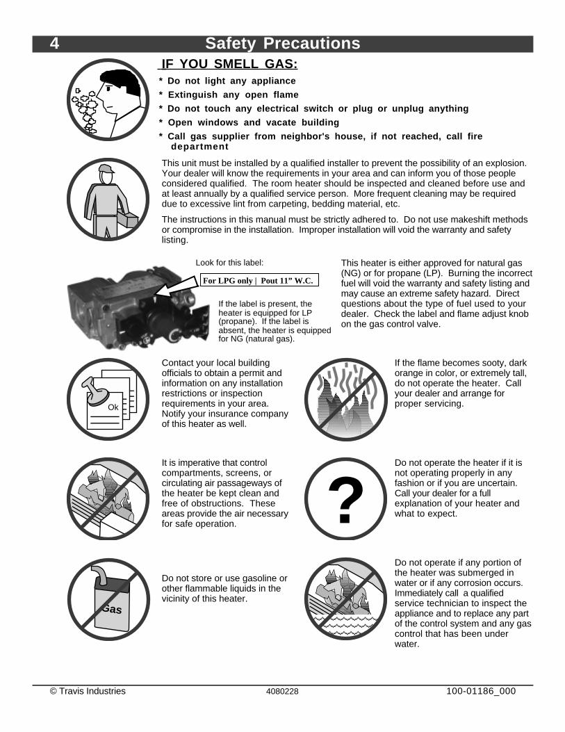
IF YOU SMELL GAS:* Do not light any appliance
* Extinguish any open flame
* Do not touch any electrical switch or plug or unplug anything
* Open windows and vacate building
* Call gas supplier from neighbor's house, if not reached, call firedepartment
This unit must be installed by a qualified installer to prevent the possibility of an explosion.Your dealer will know the requirements in your area and can inform you of those peopleconsidered qualified. The room heater should be inspected and cleaned before use andat least annually by a qualified service person. More frequent cleaning may be requireddue to excessive lint from carpeting, bedding material, etc.
The instructions in this manual must be strictly adhered to. Do not use makeshift methodsor compromise in the installation. Improper installation will void the warranty and safetylisting.
For LPG only | Pout 11” W.C.
Look for this label:
If the label is present, the heater is equipped for LP (propane). If the label is absent, the heater is equipped for NG (natural gas).
This heater is either approved for natural gas(NG) or for propane (LP). Burning the incorrectfuel will void the warranty and safety listing andmay cause an extreme safety hazard. Directquestions about the type of fuel used to yourdealer. Check the label and flame adjust knobon the gas control valve.
Ok
Contact your local buildingofficials to obtain a permit andinformation on any installationrestrictions or inspectionrequirements in your area.Notify your insurance companyof this heater as well.
If the flame becomes sooty, darkorange in color, or extremely tall,do not operate the heater. Callyour dealer and arrange forproper servicing.
It is imperative that controlcompartments, screens, orcirculating air passageways ofthe heater be kept clean andfree of obstructions. Theseareas provide the air necessaryfor safe operation. ?
Do not operate the heater if it isnot operating properly in anyfashion or if you are uncertain.Call your dealer for a fullexplanation of your heater andwhat to expect.
Gas
Do not store or use gasoline orother flammable liquids in thevicinity of this heater.
AAAAAAAAAAAAAAA
AAAAAAAAAAAAAAAAAAA
Do not operate if any portion ofthe heater was submerged inwater or if any corrosion occurs.Immediately call a qualifiedservice technician to inspect theappliance and to replace any partof the control system and any gascontrol that has been underwater.
Safety Precautions 5
© Travis Industries 4080228 100-01186_000
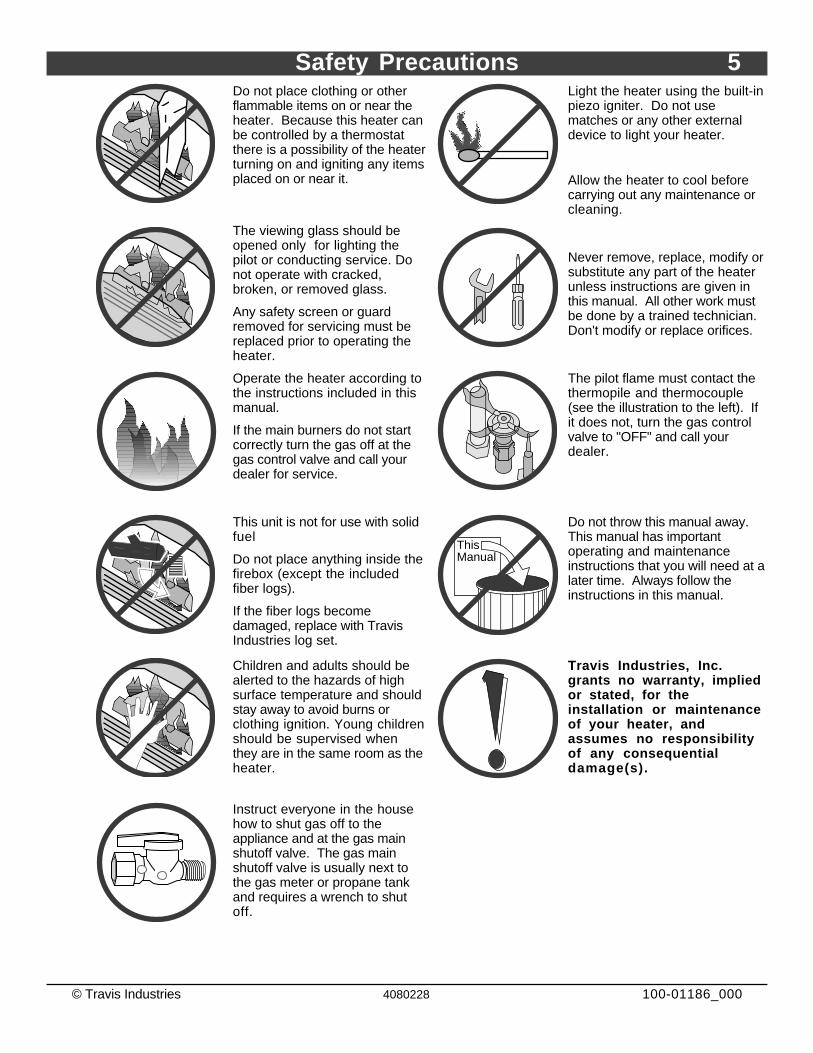
Do not place clothing or otherflammable items on or near theheater. Because this heater canbe controlled by a thermostatthere is a possibility of the heaterturning on and igniting any itemsplaced on or near it.
AAAAAAAAA
Light the heater using the built-inpiezo igniter. Do not usematches or any other externaldevice to light your heater.
Allow the heater to cool beforecarrying out any maintenance orcleaning.
The viewing glass should beopened only for lighting thepilot or conducting service. Donot operate with cracked,broken, or removed glass.
Any safety screen or guardremoved for servicing must bereplaced prior to operating theheater.
Never remove, replace, modify orsubstitute any part of the heaterunless instructions are given inthis manual. All other work mustbe done by a trained technician.Don't modify or replace orifices.
Operate the heater according tothe instructions included in thismanual.
If the main burners do not startcorrectly turn the gas off at thegas control valve and call yourdealer for service.
The pilot flame must contact thethermopile and thermocouple(see the illustration to the left). Ifit does not, turn the gas controlvalve to "OFF" and call yourdealer.
AAAAAAAA
This unit is not for use with solidfuel
Do not place anything inside thefirebox (except the includedfiber logs).
If the fiber logs becomedamaged, replace with TravisIndustries log set.
ThisManual
Do not throw this manual away.This manual has importantoperating and maintenanceinstructions that you will need at alater time. Always follow theinstructions in this manual.
Children and adults should bealerted to the hazards of highsurface temperature and shouldstay away to avoid burns orclothing ignition. Young childrenshould be supervised whenthey are in the same room as theheater.
Travis Industries, Inc.grants no warranty, impliedor stated, for theinstallation or maintenanceof your heater, andassumes no responsibilityof any consequentialdamage(s).
Instruct everyone in the househow to shut gas off to theappliance and at the gas mainshutoff valve. The gas mainshutoff valve is usually next tothe gas meter or propane tankand requires a wrench to shutoff.
6 Operation
© Travis Industries 4080228 100-01186_000
Before You Begin• Read this entire manual before you use your new fireplace (especially the section "Safety
Precautions" on pages 4 & 5). Failure to follow the instructions may result in property damage, bodilyinjury, or even death.
Location of Controls
Swing the control cover down
to access the controls.
Flame Adjust Knob
Gas
Control
ValveGas Control Knob
An instruction card for operating the fireplace
is attached to the inside of the fireplace here.
Replace it for easy reference.
Optional Blower Control
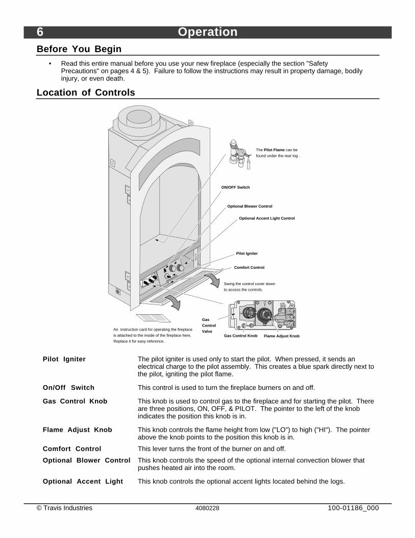
The Pilot Flame can be
found under the rear log .
Comfort Control
ON/OFF Switch
Optional Accent Light Control
Pilot Igniter
Pilot Igniter The pilot igniter is used only to start the pilot. When pressed, it sends anelectrical charge to the pilot assembly. This creates a blue spark directly next tothe pilot, igniting the pilot flame.
On/Off Switch This control is used to turn the fireplace burners on and off.
Gas Control Knob This knob is used to control gas to the fireplace and for starting the pilot. Thereare three positions, ON, OFF, & PILOT. The pointer to the left of the knobindicates the position this knob is in.
Flame Adjust Knob This knob controls the flame height from low ("LO") to high ("HI"). The pointerabove the knob points to the position this knob is in.
Comfort Control This lever turns the front of the burner on and off.
Optional Blower Control This knob controls the speed of the optional internal convection blower thatpushes heated air into the room.
Optional Accent Light This knob controls the optional accent lights located behind the logs.
Operation 7
© Travis Industries 4080228 100-01186_000
Starting The Pilot Flame
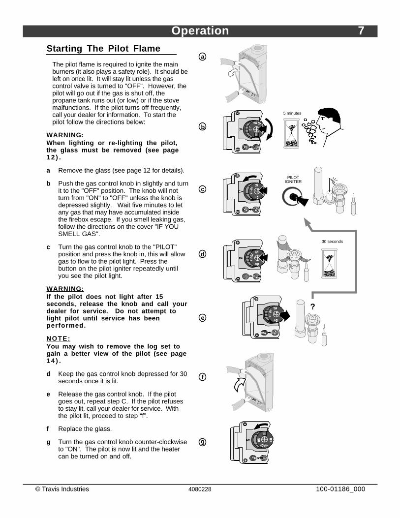
The pilot flame is required to ignite the mainburners (it also plays a safety role). It should beleft on once lit. It will stay lit unless the gascontrol valve is turned to "OFF". However, thepilot will go out if the gas is shut off, thepropane tank runs out (or low) or if the stovemalfunctions. If the pilot turns off frequently,call your dealer for information. To start thepilot follow the directions below:
WARNING :When lighting or re-lighting the pilot,the glass must be removed (see page1 2 ) .
a Remove the glass (see page 12 for details).
b Push the gas control knob in slightly and turnit to the "OFF" position. The knob will notturn from "ON" to "OFF" unless the knob isdepressed slightly. Wait five minutes to letany gas that may have accumulated insidethe firebox escape. If you smell leaking gas,follow the directions on the cover "IF YOUSMELL GAS".
c Turn the gas control knob to the "PILOT"position and press the knob in, this will allowgas to flow to the pilot light. Press thebutton on the pilot igniter repeatedly untilyou see the pilot light.
WARNING:If the pilot does not light after 15seconds, release the knob and call yourdealer for service. Do not attempt tolight pilot until service has beenperformed.
NOTE:You may wish to remove the log set togain a better view of the pilot (see page1 4 ) .
d Keep the gas control knob depressed for 30seconds once it is lit.
e Release the gas control knob. If the pilotgoes out, repeat step C. If the pilot refusesto stay lit, call your dealer for service. Withthe pilot lit, proceed to step “f”.
f Replace the glass.
g Turn the gas control knob counter-clockwiseto "ON". The pilot is now lit and the heatercan be turned on and off.
?
AAAAAAAA
AAAA
30 seconds
PILOT IGNITER
a
b
AAAAAAAA
AAAA
5 minutes
c
d
e
f
g
8 Operation
© Travis Industries 4080228 100-01186_000
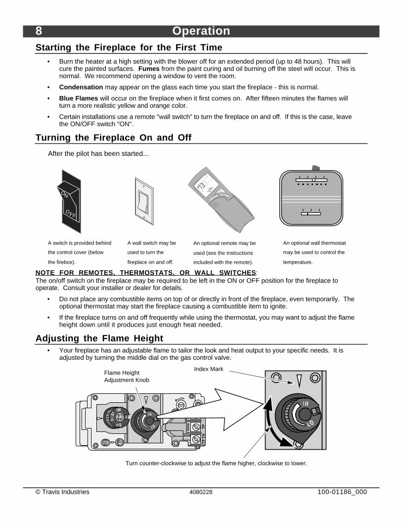
Starting the Fireplace for the First Time• Burn the heater at a high setting with the blower off for an extended period (up to 48 hours). This will
cure the painted surfaces. Fumes from the paint curing and oil burning off the steel will occur. This isnormal. We recommend opening a window to vent the room.
• Condensation may appear on the glass each time you start the fireplace - this is normal.
• Blue Flames will occur on the fireplace when it first comes on. After fifteen minutes the flames willturn a more realistic yellow and orange color.
• Certain installations use a remote "wall switch" to turn the fireplace on and off. If this is the case, leavethe ON/OFF switch "ON".
Turning the Fireplace On and Off
After the pilot has been started...
OFF
ON
A switch is provided behind
the control cover (below
the firebox).
An optional remote may be
used (see the instructions
included with the remote).
An optional wall thermostat
may be used to control the
temperature.
A wall switch may be
used to turn the
fireplace on and off.
ROOM
SETOFF
UP
DOWN
MODE
TIME
LIGHT
AMFM
NOTE FOR REMOTES, THERMOSTATS, OR WALL SWITCHES :The on/off switch on the fireplace may be required to be left in the ON or OFF position for the fireplace tooperate. Consult your installer or dealer for details.
• Do not place any combustible items on top of or directly in front of the fireplace, even temporarily. Theoptional thermostat may start the fireplace causing a combustible item to ignite.
• If the fireplace turns on and off frequently while using the thermostat, you may want to adjust the flameheight down until it produces just enough heat needed.
Adjusting the Flame Height• Your fireplace has an adjustable flame to tailor the look and heat output to your specific needs. It is
adjusted by turning the middle dial on the gas control valve.
Flame Height Adjustment Knob
Index Mark
Turn counter-clockwise to adjust the flame higher, clockwise to lower.
Operation 9
© Travis Industries 4080228 100-01186_000
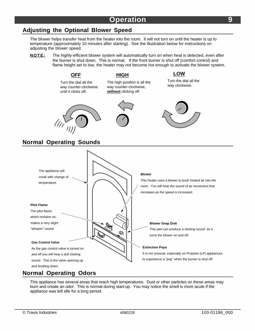
Adjusting the Optional Blower SpeedThe blower helps transfer heat from the heater into the room. It will not turn on until the heater is up totemperature (approximately 10 minutes after starting). See the illustration below for instructions onadjusting the blower speed.
NOTE: The highly-efficient blower system will automatically turn on when heat is detected, even afterthe burner is shut down. This is normal. If the front burner is shut off (comfort control) andflame height set to low, the heater may not become hot enough to activate the blower system.
OFFTurn the dial all the way counter-clockwise until it clicks off.
HIGHThe high position is all the way counter-clockwise, without clicking off.
LOWTurn the dial all the way clockwise.
Normal Operating Sounds
Gas Control Valve
As the gas control valve is turned on
and off you will hear a dull clicking
sound. This is the valve opening up
and shutting down.
Blower Snap Disk
This part can produce a clicking sound as it
turns the blower on and off.
The appliance will
creak with change of
temperature.
Pilot Flame
The pilot flame,
which remains on,
makes a very slight
"whisper" sound.
Blower
This heater uses a blower to push heated air into the
room. You will hear the sound of air movement that
increases as the speed is increased.
Extinction Pops
It is not unusual, especially on Propane (LP) appliances,
to experience a "pop" when the burner is shut off.
Normal Operating OdorsThis appliance has several areas that reach high temperatures. Dust or other particles on these areas mayburn and create an odor. This is normal during start-up. You may notice the smell is more acute if theappliance was left idle for a long period.
10 Maintenance
© Travis Industries 4080228 100-01186_000
Maintaining Your Fireplace's AppearanceFingerprints or other marks left on the optional plated surface may become etched in place if they are notwiped clean prior to turning the fireplace on. Clean the plated surface with denatured alcohol and a softcloth (with the fireplace cool). Other cleaners may leave a film that may become etched into the surface.
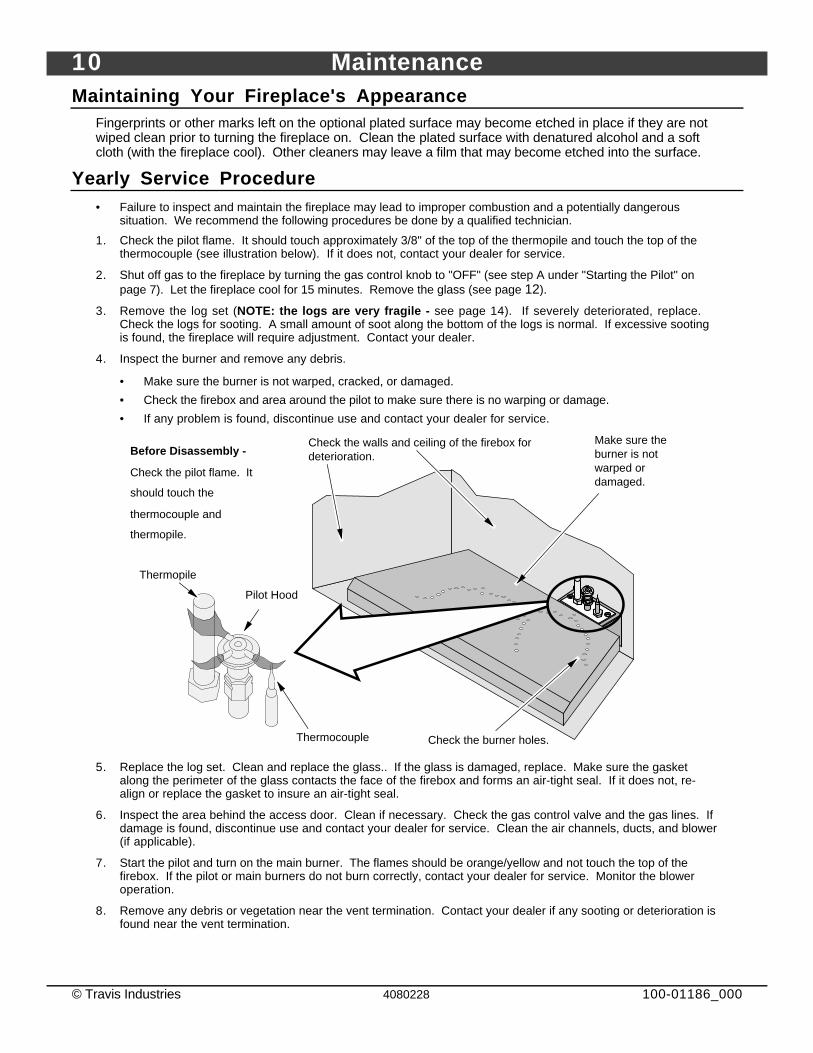
Yearly Service Procedure• Failure to inspect and maintain the fireplace may lead to improper combustion and a potentially dangerous
situation. We recommend the following procedures be done by a qualified technician.
1. Check the pilot flame. It should touch approximately 3/8" of the top of the thermopile and touch the top of thethermocouple (see illustration below). If it does not, contact your dealer for service.
2. Shut off gas to the fireplace by turning the gas control knob to "OFF" (see step A under "Starting the Pilot" onpage 7). Let the fireplace cool for 15 minutes. Remove the glass (see page 12).
3. Remove the log set (NOTE: the logs are very fragile - see page 14). If severely deteriorated, replace.Check the logs for sooting. A small amount of soot along the bottom of the logs is normal. If excessive sootingis found, the fireplace will require adjustment. Contact your dealer.
4. Inspect the burner and remove any debris.
• Make sure the burner is not warped, cracked, or damaged.
• Check the firebox and area around the pilot to make sure there is no warping or damage.
• If any problem is found, discontinue use and contact your dealer for service.
AAAAAAA
Check the burner holes.
Make sure the burner is not warped or damaged.
Check the walls and ceiling of the firebox for deterioration.
Thermopile
Pilot Hood
Thermocouple
Before Disassembly -
Check the pilot flame. It
should touch the
thermocouple and
thermopile.
5. Replace the log set. Clean and replace the glass.. If the glass is damaged, replace. Make sure the gasketalong the perimeter of the glass contacts the face of the firebox and forms an air-tight seal. If it does not, re-align or replace the gasket to insure an air-tight seal.
6. Inspect the area behind the access door. Clean if necessary. Check the gas control valve and the gas lines. Ifdamage is found, discontinue use and contact your dealer for service. Clean the air channels, ducts, and blower(if applicable).
7. Start the pilot and turn on the main burner. The flames should be orange/yellow and not touch the top of thefirebox. If the pilot or main burners do not burn correctly, contact your dealer for service. Monitor the bloweroperation.
8. Remove any debris or vegetation near the vent termination. Contact your dealer if any sooting or deterioration isfound near the vent termination.
Maintenance 11
© Travis Industries 4080228 100-01186_000
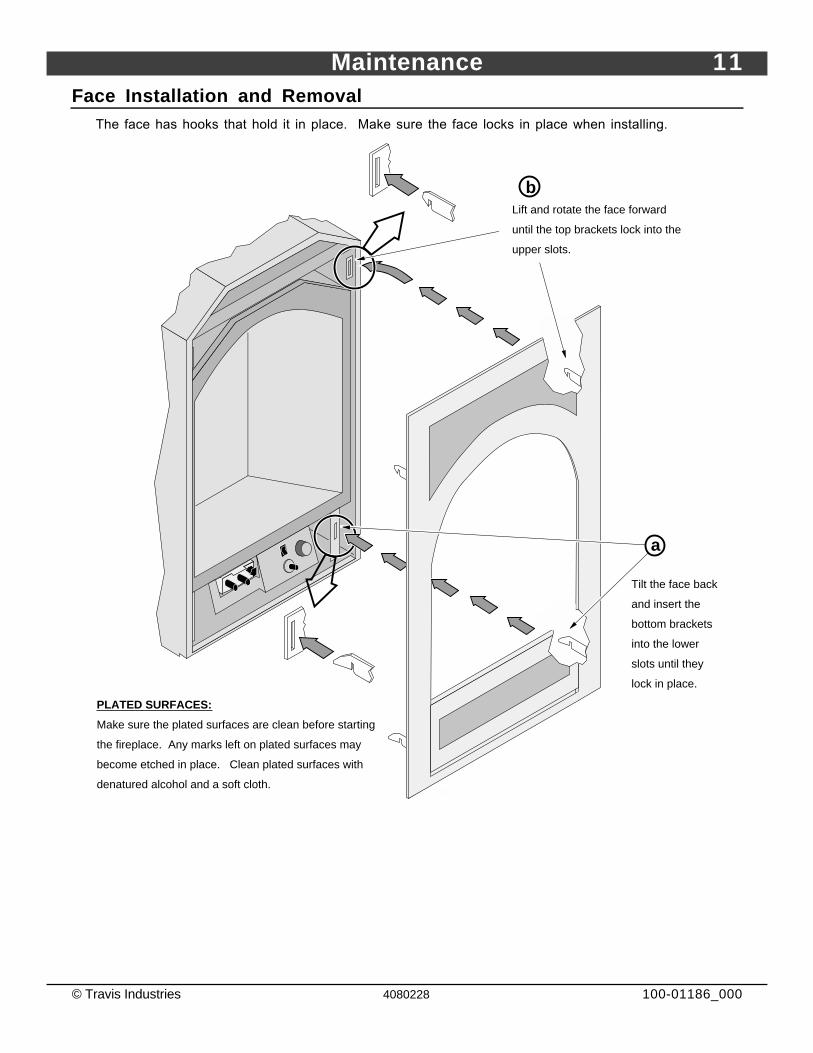
Face Installation and RemovalThe face has hooks that hold it in place. Make sure the face locks in place when installing.
Tilt the face back
and insert the
bottom brackets
into the lower
slots until they
lock in place.
PLATED SURFACES:
Make sure the plated surfaces are clean before starting
the fireplace. Any marks left on plated surfaces may
become etched in place. Clean plated surfaces with
denatured alcohol and a soft cloth.
Lift and rotate the face forward
until the top brackets lock into the
upper slots.
b
a
12 Maintenance
© Travis Industries 4080228 100-01186_000
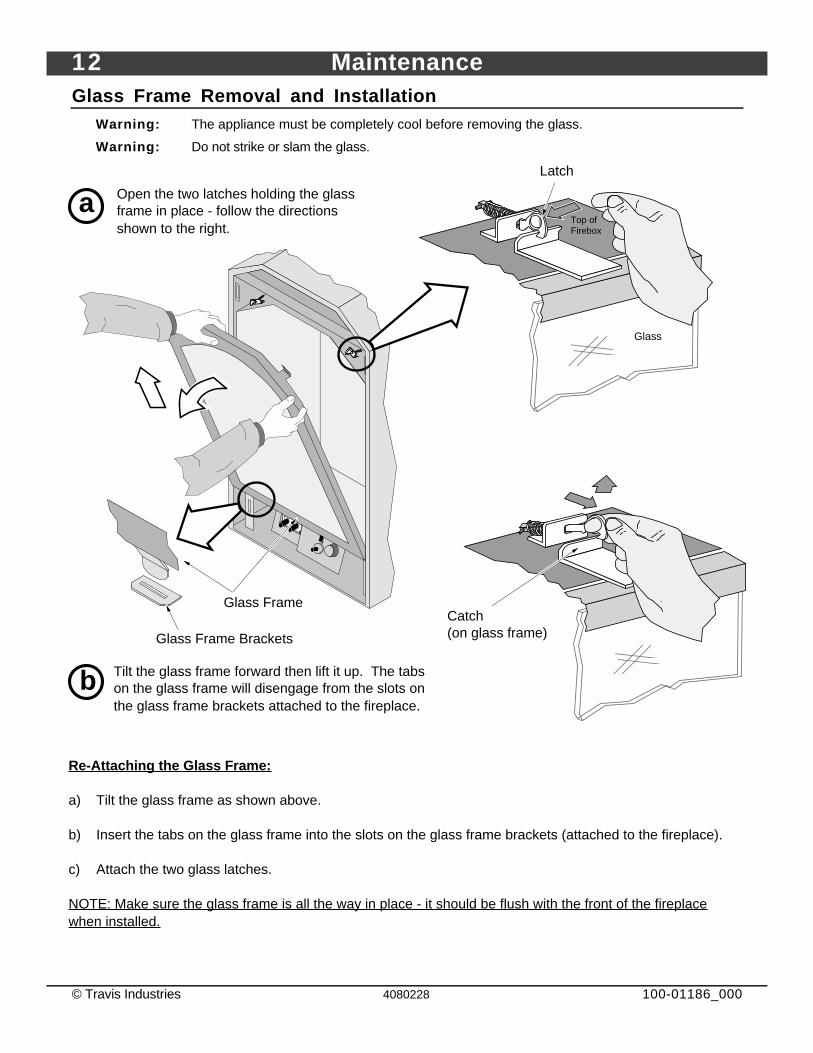
Glass Frame Removal and InstallationWarning: The appliance must be completely cool before removing the glass.
Warning: Do not strike or slam the glass.
Open the two latches holding the glass frame in place - follow the directions shown to the right.
a
Glass Frame
Tilt the glass frame forward then lift it up. The tabs on the glass frame will disengage from the slots on the glass frame brackets attached to the fireplace.
b
Re-Attaching the Glass Frame:
a) Tilt the glass frame as shown above.
b) Insert the tabs on the glass frame into the slots on the glass frame brackets (attached to the fireplace).
c) Attach the two glass latches.
NOTE: Make sure the glass frame is all the way in place - it should be flush with the front of the fireplace when installed.
Glass
Top of Firebox
Latch
Catch (on glass frame)Glass Frame Brackets
Maintenance 13
© Travis Industries 4080228 100-01186_000
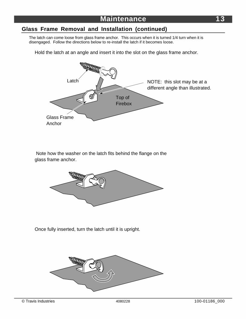
Glass Frame Removal and Installation (continued)The latch can come loose from glass frame anchor. This occurs when it is turned 1/4 turn when it isdisengaged. Follow the directions below to re-install the latch if it becomes loose.
Top of Firebox
Hold the latch at an angle and insert it into the slot on the glass frame anchor.
NOTE: this slot may be at a different angle than illustrated.
Note how the washer on the latch fits behind the flange on the glass frame anchor.
Glass Frame Anchor
Once fully inserted, turn the latch until it is upright.
Latch
14 Maintenance
© Travis Industries 4080228 100-01186_000
Log Set Installation
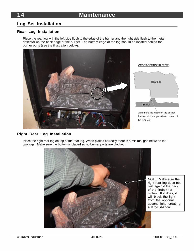
Rear Log Installation
Place the rear log with the left side flush to the edge of the burner and the right side flush to the metaldeflector on the back edge of the burner. The bottom edge of the log should be located behind theburner ports (see the illustration below).
Rear Log
Burner
Make sure the ledge on the burner
lines up with stepped-down portion of
the rear log.
CROSS-SECTIONAL VIEW
Right Rear Log Installation
Place the right rear log on top of the rear log. When placed correctly there is a minimal gap between thetwo logs. Make sure the bottom is placed so no burner ports are blocked.
NOTE: Make sure theright rear log does notrest against the backof the firebox (orniche). If it does, itwill block the lightfrom the optionalaccent light, creatinga large shadow.
Maintenance 15
© Travis Industries 4080228 100-01186_000
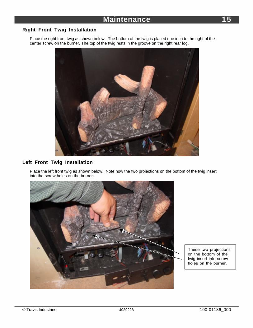
Right Front Twig Installation
Place the right front twig as shown below. The bottom of the twig is placed one inch to the right of thecenter screw on the burner. The top of the twig rests in the groove on the right rear log.
Left Front Twig Installation
Place the left front twig as shown below. Note how the two projections on the bottom of the twig insertinto the screw holes on the burner.
These two projectionson the bottom of thetwig insert into screwholes on the burner.
16 Maintenance
© Travis Industries 4080228 100-01186_000
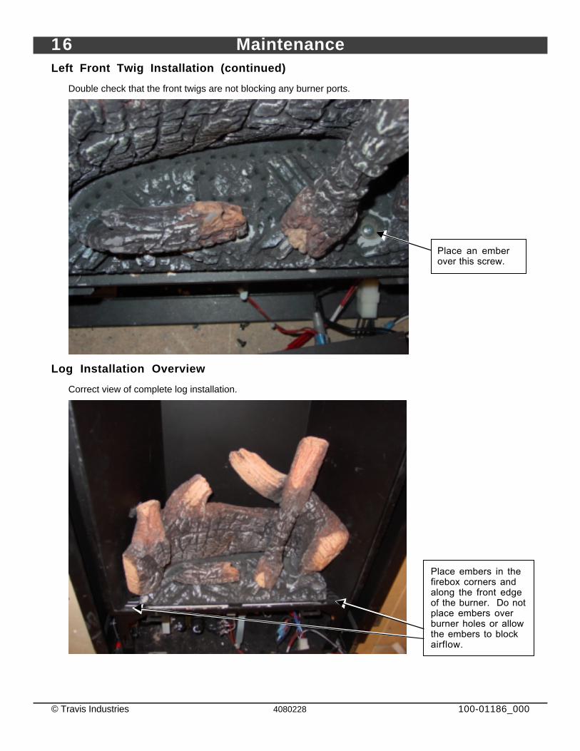
Left Front Twig Installation (continued)
Double check that the front twigs are not blocking any burner ports.
Log Installation Overview
Correct view of complete log installation.
Place an emberover this screw.
Place embers in thefirebox corners andalong the front edgeof the burner. Do notplace embers overburner holes or allowthe embers to blockairflow.
Maintenance 17
© Travis Industries 4080228 100-01186_000
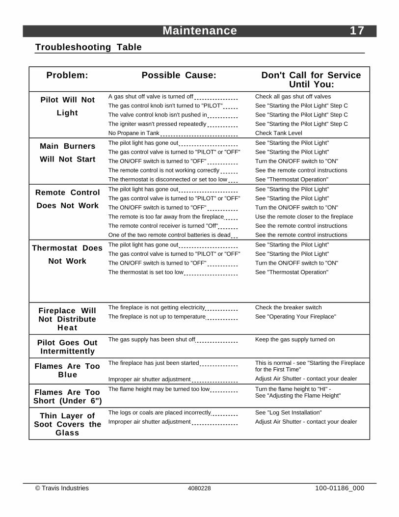
Troubleshooting Table
Problem: Possible Cause: Don't Call for ServiceUntil You:
Pilot Will Not
Light
A gas shut off valve is turned off
The gas control knob isn't turned to "PILOT"
The valve control knob isn't pushed in
The igniter wasn't pressed repeatedly
No Propane in Tank
Check all gas shut off valves
See "Starting the Pilot Light" Step C
See "Starting the Pilot Light" Step C
See "Starting the Pilot Light" Step C
Check Tank Level
Main Burners
Will Not Start
The pilot light has gone out
The gas control valve is turned to "PILOT" or "OFF"
The ON/OFF switch is turned to "OFF"
The remote control is not working correctly
The thermostat is disconnected or set too low
See "Starting the Pilot Light"
See "Starting the Pilot Light"
Turn the ON/OFF switch to "ON"
See the remote control instructions
See "Thermostat Operation"
Remote Control
Does Not Work
The pilot light has gone out
The gas control valve is turned to "PILOT" or "OFF"
The ON/OFF switch is turned to "OFF"
The remote is too far away from the fireplace
The remote control receiver is turned "Off"
One of the two remote control batteries is dead
See "Starting the Pilot Light"
See "Starting the Pilot Light"
Turn the ON/OFF switch to "ON"
Use the remote closer to the fireplace
See the remote control instructions
See the remote control instructions
Thermostat Does
Not Work
The pilot light has gone out
The gas control valve is turned to "PILOT" or "OFF"
The ON/OFF switch is turned to "OFF"
The thermostat is set too low
See "Starting the Pilot Light"
See "Starting the Pilot Light"
Turn the ON/OFF switch to "ON"
See "Thermostat Operation"
Fireplace WillNot Distribute
Heat
The fireplace is not getting electricity
The fireplace is not up to temperature
Check the breaker switch
See "Operating Your Fireplace"
Pilot Goes OutIntermittently
The gas supply has been shut off Keep the gas supply turned on
Flames Are TooBlue
The fireplace has just been started
Improper air shutter adjustment
This is normal - see "Starting the Fireplacefor the First Time"
Adjust Air Shutter - contact your dealer
Flames Are TooShort (Under 6")
The flame height may be turned too low Turn the flame height to "HI" -See "Adjusting the Flame Height"
Thin Layer ofSoot Covers the
Glass
The logs or coals are placed incorrectly
Improper air shutter adjustment
See "Log Set Installation"
Adjust Air Shutter - contact your dealer
18 Maintenance
© Travis Industries 4080228 100-01186_000
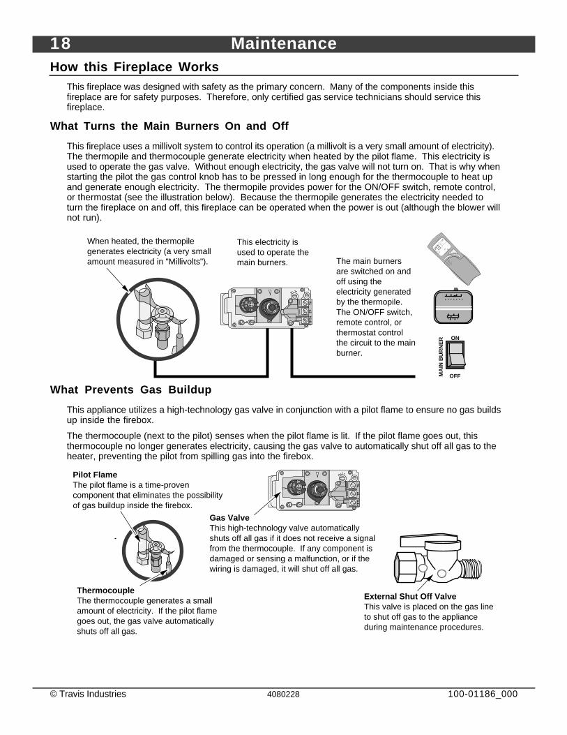
How this Fireplace WorksThis fireplace was designed with safety as the primary concern. Many of the components inside thisfireplace are for safety purposes. Therefore, only certified gas service technicians should service thisfireplace.
What Turns the Main Burners On and Off
This fireplace uses a millivolt system to control its operation (a millivolt is a very small amount of electricity).The thermopile and thermocouple generate electricity when heated by the pilot flame. This electricity isused to operate the gas valve. Without enough electricity, the gas valve will not turn on. That is why whenstarting the pilot the gas control knob has to be pressed in long enough for the thermocouple to heat upand generate enough electricity. The thermopile provides power for the ON/OFF switch, remote control,or thermostat (see the illustration below). Because the thermopile generates the electricity needed toturn the fireplace on and off, this fireplace can be operated when the power is out (although the blower willnot run).
When heated, the thermopile generates electricity (a very small amount measured in "Millivolts").
This electricity is used to operate the main burners. The main burners
are switched on and off using the electricity generated by the thermopile. The ON/OFF switch, remote control, or thermostat control the circuit to the main burner.
ON
OFFMA
IN B
UR
NE
R
ROOM
SETOFF
UPDOWN
MODE
TIME
LIGHT
AMFM
What Prevents Gas Buildup
This appliance utilizes a high-technology gas valve in conjunction with a pilot flame to ensure no gas buildsup inside the firebox.
The thermocouple (next to the pilot) senses when the pilot flame is lit. If the pilot flame goes out, thisthermocouple no longer generates electricity, causing the gas valve to automatically shut off all gas to theheater, preventing the pilot from spilling gas into the firebox.
Gas ValveThis high-technology valve automatically shuts off all gas if it does not receive a signal from the thermocouple. If any component is damaged or sensing a malfunction, or if the wiring is damaged, it will shut off all gas.
Pilot FlameThe pilot flame is a time-proven component that eliminates the possibility of gas buildup inside the firebox.
ThermocoupleThe thermocouple generates a small amount of electricity. If the pilot flame goes out, the gas valve automatically shuts off all gas.
External Shut Off ValveThis valve is placed on the gas line to shut off gas to the appliance during maintenance procedures.
Maintenance 19
© Travis Industries 4080228 100-01186_000
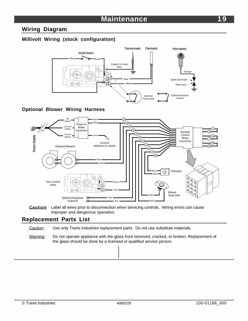
Wiring Diagram
Millivolt Wiring (stock configuration)
Orange
White
Piezo IgniterThermopile
Red
AA
Thermocouple
Copper Co-Axial Wire
Red
Optional Remote Control
Spark Electrode
Pilot Hood
On/Off Switch
Brown
Optional Thermostat
Optional Blower Wiring Harness
74
109
13
Optional Blowers
Green
Hot (black)
Common (white)
Ground (green)
Blower Snap Disk
Power In Molex
Connector
Po
wer
Su
pp
ly
Ground (attached to stove)
White
Black
1
35
7
24
68
9
1211
10
36
White
9
25
Black
Remote Control Molex
Connector8
11
Blue
Blue
Optional Regulator Solenoid
1
4
Black
Black
7
Black
Black
10
Red
Brown
Rheostat
Gas Control Valve
Caution : Label all wires prior to disconnection when servicing controls. Wiring errors can causeimproper and dangerous operation.
Replacement Parts ListCaution : Use only Travis Industries replacement parts. Do not use substitute materials.
Warning : Do not operate appliance with the glass front removed, cracked, or broken. Replacement ofthe glass should be done by a licensed or qualified service person.
20 Limited 7 Year Warranty
© Travis Industries 4080228 100-01186_000
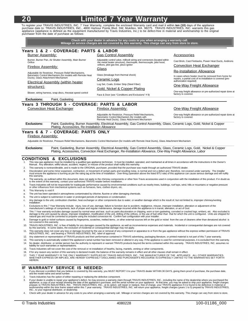
To register your TRAVIS INDUSTRIES, INC. 7 Year Warranty, complete the enclosed Warranty card and mail it within ten (10) days of the appliancepurchase date to: TRAVIS INDUSTRIES, INC., 4800 Harbour Pointe Blvd. SW, Mukilteo, WA 98275. TRAVIS INDUSTRIES, INC. warrants this gasappliance (appliance is defined as the equipment manufactured by Travis Industries, Inc.) to be defect-free in material and workmanship to the originalpurchaser from the date of purchase as follows:
Check with your dealer in advance for any costs to you when arranging a warranty call.Mileage or service charges are not covered by this warranty. This charge can vary from store to store.
Years 1 & 2 - COVERAGE: PARTS & LABORBurner Assembly:Burner, Burner Pan, Air Shutter Assembly, Main BurnerOrifice
Firebox Assembly:
Adjustable Air Restrictor, Pressure Relief Mechanisms,Barometric Control Mechanism (for models with Remote HeatDucts), Glass Attachment Mechanism
Electrical Assembly (within heaterstructure):
Blower, wiring harness, snap discs, rheostat speed control
Gas Control AssemblyAdjustable control valve, millivolt wiring and connectors (located withinthe metal heater structure), thermopile, thermocouple, pilot hood,orifices, pilot gas line, piezo ignitor
Glass
Glass (breakage from thermal shock)
Ceramic LogsLog Set, Coals, Ember Strip (Steel Fiber)
Gold, Nickel & Copper Plating
Face & Door (see “Conditions and Exclusions” # 9)
Accessories
Cast Brick, Cast Firebacks, Power Heat Ducts, Andirons
Convection Heat Exchanger
Re-Installation AllowanceIn cases where heater must be removed from home forrepairs, a partial cost of re-installation is covered (pre-authorization required)
One-Way Freight Allowance
One-way freight allowance on pre-authorized repair done atfactory is covered.
Exclusions: Paint, Gasketing
Years 3 THROUGH 5 - COVERAGE: PARTS & LABORConvection Heat Exchanger Firebox Assembly:
Adjustable Air Restrictor, Pressure Relief Mechanisms,Barometric Control Mechanism (for models withRemote Heat Ducts), Glass Attachment Mechanism
One-Way Freight Allowance
One-way freight allowance on pre-authorized repair done atfactory is covered.
Exclusions: Paint, Gasketing, Burner Assembly, Electrical Assembly, Gas Control Assembly, Glass, Ceramic Logs, Gold, Nickel & CopperPlating, Accessories, Re-Installation Allowance
Years 6 & 7 - COVERAGE: PARTS ONLYFirebox Assembly:Adjustable Air Restrictor, Pressure Relief Mechanisms, Barometric Control Mechanism (for models with Remote Heat Ducts), Glass Attachment Mechanism
Exclusions: Paint, Gasketing, Burner Assembly, Electrical Assembly, Gas Control Assembly, Glass, Ceramic Logs, Gold, Nickel & CopperPlating, Accessories, Convection Heat Exchanger, Re-Installation Allowance, One-Way Freight Allowance, Labor
CONDITIONS & EXCLUSIONS1. This new gas appliance must be installed by a qualified gas appliance technician. It must be installed, operated, and maintained at all times in accordance with the instructions in the Owner’s
Manual. Any alteration, willful abuse, accident, neglect, or misuse of the product shall nullify this warranty.2. This warranty is nontransferable, and is made to the ORIGINAL purchaser, provided that the purchase was made through an authorized TRAVIS dealer.3. Discoloration and some minor expansion, contraction, or movement of certain parts and resulting noise, is normal and not a defect and, therefore, not covered under warranty. The installer
must ensure the appliance is burning as per the rating tag at the time of installation. Over-firing (operation above the listed BTU rate) of this appliance can cause serious damage and will nullifythis warranty.
4. The warranty, as outlined within this document, does not apply to the chimney components or other Non-Travis accessories used in conjunction with the installation of this product. If in doubt asto the extent of this warranty, contact your authorized TRAVIS retailer before installation.
5. Travis Industries will not be responsible for inadequate performance caused by environmental conditions such as nearby trees, buildings, roof tops, wind, hills or mountains or negative pressureor other influences from mechanical systems such as furnaces, fans, clothes dryers, etc.
6. This Warranty is void if:a. The unit has been operated in atmospheres contaminated by chlorine, fluorine or other damaging chemicals.b. The unit is subject to submersion in water or prolonged periods of dampness or condensation.c. Any damage to the unit, combustion chamber, heat exchanger or other components due to water, or weather damage which is the result of, but not limited to, improper chimney/venting
installation.7. Exclusions to this 7 Year Warranty include: injury, loss of use, damage, failure to function due to accident, negligence, misuse, improper installation, alteration or adjustment of the
manufacturer's settings of components, lack of proper and regular maintenance, damage incurred while the appliance is in transit, alteration, or act of God.8. This 7 Year warranty excludes damage caused by normal wear and tear, such as paint discoloration or chipping, worn or torn gasketing, corroded or cracked logs, embers, etc. Also excluded is
damage to the unit caused by abuse, improper installation, modification of the unit, drilling of the orifices, or the use of fuel other than that for which the unit is configured. Units are shipped fornatural gas and must be converted to propane using the included conversion kit. Confirm fuel configuration with your installer.
9. Damage to gold or nickel surfaces caused by fingerprints, scratches, melted items , or other external sources left on the gold or nickel from the use of cleaners other than denatured alcohol isnot covered in this warranty.
10. TRAVIS INDUSTRIES, INC. is free of liability for any damages caused by the appliance, as well as inconvenience expenses and materials. Incidental or consequential damages are not coveredby this warranty. In some states, the exclusion of incidental or consequential damage may not apply.
11. This warranty does not cover any loss or damage incurred by the use or removal of any component or apparatus to or from the gas appliance without the express written permission of TRAVISINDUSTRIES, INC. and bearing a TRAVIS INDUSTRIES, INC. label of approval.
12. Any statement or representation of TRAVIS products and their performance contained in TRAVIS advertising, packaging literature, or printed material is not part of this 7 year warranty.13. This warranty is automatically voided if the appliance’s serial number has been removed or altered in any way. If the appliance is used for commercial purposes, it is excluded from this warranty.14. No dealer, distributor, or similar person has the authority to represent or warrant TRAVIS products beyond the terms contained within this warranty. TRAVIS INDUSTRIES, INC. assumes no
liability for such warranties or representations.15. Travis Industries will not cover the cost of the removal or re-installation of hearths, facing, mantels, venting or other components.16. If for any reason any section of this warranty is declared invalid, the balance of the warranty remains in effect and all other clauses shall remain in effect.17. THIS 7 YEAR WARRANTY IS THE ONLY WARRANTY SUPPLIED BY TRAVIS INDUSTRIES, INC., THE MANUFACTURER OF THE APPLIANCE. ALL OTHER WARRANTIES,
WHETHER EXPRESS OR IMPLIED, ARE HEREBY EXPRESSLY DISCLAIMED AND PURCHASER’S RECOURSE IS EXPRESSLY LIMITED TO THE WARRANTIES SET FORTHHEREIN.
IF WARRANTY SERVICE IS NEEDED:1. If you discover a problem that you believe is covered by this warranty, you MUST REPORT it to your TRAVIS dealer WITHIN 30 DAYS, giving them proof of purchase, the purchase date,
and the model name and serial number.2. Travis Industries has the option of either repairing or replacing the defective component.3. If your dealer is unable to repair your appliance’s defect, he may process a warranty claim through TRAVIS INDUSTRIES, INC., including the name of the dealership where you purchased the
appliance, a copy of your receipt showing the date of the appliance’s purchase, and the serial number on your appliance. At that time, you may be asked to ship your appliance, freight chargesprepaid, to TRAVIS INDUSTRIES, INC. TRAVIS INDUSTRIES, INC., at its option, will repair or replace, free of charge, your TRAVIS appliance if it is found to be defective in material orworkmanship within the time frame stated within this 7 year warranty. TRAVIS INDUSTRIES, INC. will return your appliance, freight charges (years 1 to 5) prepaid by TRAVIS INDUSTRIES,INC., to your regional distributor, or dealership.
4. Check with your dealer in advance for any costs to you when arranging a warranty call. Mileage or service charges are not covered by this warranty. This charge can vary from store to store.
Optional Equipment 21
© Travis Industries 4080228 100-01186_000
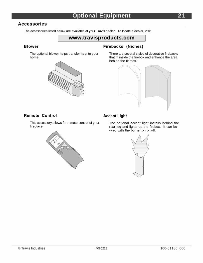
AccessoriesThe accessories listed below are available at your Travis dealer. To locate a dealer, visit:
www.travisproducts.com
Blower
The optional blower helps transfer heat to yourhome.
Firebacks (Niches)
There are several styles of decorative firebacksthat fit inside the firebox and enhance the areabehind the flames.
Remote Control
This accessory allows for remote control of yourfireplace.
ROOM
SETOFF
UP
DOWN
MODE
TIME
LIGHT
AMFM
Accent Light
The optional accent light installs behind therear log and lights up the firebox. It can beused with the burner on or off.
22 Index
© Travis Industries 4080228 100-01186_000
Index
Accessories.......................................................21Adjusting the Flame Height ....................................8Adjusting the Optional Blower Speed.......................9Before You Begin ................................................6Blower Operation (optional) ...................................9Cleaning............................................................10Controls - Location ..............................................6Features............................................................3Flame Height Adjustment ......................................8Glass Frame Removal and Installation.....................12Face Installation and Removal ...............................11Heating Specifications .........................................3How this Fireplace Works......................................18Important Information...........................................2Installation Warnings ...........................................2Introduction .......................................................2Location of Controls.............................................6Log Set Installation..............................................14Maintaining Your Fireplace's Appearance.................10
Normal Operating Odors....................................... 9Normal Operating Sounds..................................... 9Odors............................................................... 9On/Off Operation................................................ 8Optional Equipment List ....................................... 21Parts................................................................ 19Pilot - Starting.................................................... 6Replacement Parts List........................................ 19Safety Precautions............................................. 4Smells .............................................................. 9Starting the Fireplace for the First Time ................... 8Starting The Pilot Flame ....................................... 6Troubleshooting Table ......................................... 17Turning the Fireplace On and Off............................ 8Warranty........................................................... 26Window Removal and Installation........................... 12Wiring Diagram................................................... 19Yearly Service Procedure..................................... 10