Dunix sys operating
306
Digital UNIX System Administration Course Guide, Volume 1 Order Number: EY-U659E-S1.0002
-
Upload
ivo-carvalho -
Category
Software
-
view
289 -
download
2
Transcript of Dunix sys operating

Digital UNIX System AdministrationCourse Guide, Volume 1Order Number: EY-U659E-S1.0002

September 1996
Digital Equipment Corporation makes no representations that the use of its productsin the manner described in this publication will not infringe on existing or futurepatent rights, nor do the descriptions contained in this publication imply the grantingof licenses to make, use, or sell equipment or software in accordance with thedescription.
Reproduction or duplication of this courseware in any form, in whole or in part, isprohibited without the prior written permission of Digital Equipment Corporation.
Possession, use, or copying of the software described in this publication is authorizedonly pursuant to a valid written license from Digital or an authorized sublicensor.
© Digital Equipment Corporation 1995, 1996. All rights reserved. Printed in U.S.A.
The following are trademarks of Digital Equipment Corporation: Alpha AXP,CompacTape, DEC, DECevent, DEC VET, DEC Fortran, DECthreads, DEC Chip,DECnet, DECwindows, Digital, DNA, LAT, POLYCENTER, OpenVMS, TURBOchannel,ULTRIX, and the DIGITAL logo.
The following are third-party trademarks used in this course:
AIX is a registered trademark of International Business Machines Corp.Futurebus/Plus is a registered trademark of Force Computers GMBH, Federal Republicof Germany.Global Knowledge Network and the Global Knowledge Network logo are trademarks ofGlobal Knowledge Network, Inc.IEEE is a registered trademark of the Institute of Electrical and Electronics Engineers,Inc.Motif, OSF and OSF/1 are registered trademarks of the Open Software Foundation.MS–DOS is a registered trademark of Microsoft Corporation.NFS is a registered trademark of Sun Microsystems, Inc.Open Software Foundation is a trademark of the Open Software Foundation.POSIX is a registered trademark of the Institute of Electrical and Electronics.PostScript is a registered trademark of Adobe Systems, Inc.NFS and Sun Microsystems are registered trademarks of Sun Microsystems, Inc.UNIX is a registered trademark in the United States and other countries licensedexclusively through X/Open Company Ltd.X Window System is a trademark of the Massachusetts Institute of Technology.
This document was prepared using VAX DOCUMENT Version 2.1.
Contents
About This Course . . . . . . . . . . . . . . . . . . . . . . . . . . . . . . . . . . . . . . . . . . . . . . . . . xvii
1 Introducing UNIX System Management
About This Chapter . . . . . . . . . . . . . . . . . . . . . . . . . . . . . . . . . . . . . . . . . . 1–2Introduction . . . . . . . . . . . . . . . . . . . . . . . . . . . . . . . . . . . . . . . . . . . . . 1–2Objectives . . . . . . . . . . . . . . . . . . . . . . . . . . . . . . . . . . . . . . . . . . . . . . . 1–2Resources . . . . . . . . . . . . . . . . . . . . . . . . . . . . . . . . . . . . . . . . . . . . . . . 1–3
System Manager Responsibilities . . . . . . . . . . . . . . . . . . . . . . . . . . . . . . . 1–4Overview . . . . . . . . . . . . . . . . . . . . . . . . . . . . . . . . . . . . . . . . . . . . . . . 1–4
UNIX Software Environment . . . . . . . . . . . . . . . . . . . . . . . . . . . . . . . . . . . 1–6Overview . . . . . . . . . . . . . . . . . . . . . . . . . . . . . . . . . . . . . . . . . . . . . . . 1–6The Kernel . . . . . . . . . . . . . . . . . . . . . . . . . . . . . . . . . . . . . . . . . . . . . . 1–7
Digital UNIX Features . . . . . . . . . . . . . . . . . . . . . . . . . . . . . . . . . . . . . . . 1–8Digital UNIX Components . . . . . . . . . . . . . . . . . . . . . . . . . . . . . . . . . . 1–8Digital UNIX Features . . . . . . . . . . . . . . . . . . . . . . . . . . . . . . . . . . . . 1–8File System Support . . . . . . . . . . . . . . . . . . . . . . . . . . . . . . . . . . . . . . 1–9
Digital UNIX System Internals . . . . . . . . . . . . . . . . . . . . . . . . . . . . . . . . . 1–10Overview . . . . . . . . . . . . . . . . . . . . . . . . . . . . . . . . . . . . . . . . . . . . . . . 1–10User Process Creation . . . . . . . . . . . . . . . . . . . . . . . . . . . . . . . . . . . . . 1–10Daemon Processes . . . . . . . . . . . . . . . . . . . . . . . . . . . . . . . . . . . . . . . . 1–11Process Environment: Scheduling and Priority . . . . . . . . . . . . . . . . . . 1–11Real Time Processing . . . . . . . . . . . . . . . . . . . . . . . . . . . . . . . . . . . . . . 1–13Memory Management: Paging and Swapping . . . . . . . . . . . . . . . . . . . 1–13Block versus Character I/O . . . . . . . . . . . . . . . . . . . . . . . . . . . . . . . . . 1–14
Superuser and the Root Login . . . . . . . . . . . . . . . . . . . . . . . . . . . . . . . . . . 1–15Superuser Privileges . . . . . . . . . . . . . . . . . . . . . . . . . . . . . . . . . . . . . . 1–15Root Security . . . . . . . . . . . . . . . . . . . . . . . . . . . . . . . . . . . . . . . . . . . . 1–15Root Login Procedure . . . . . . . . . . . . . . . . . . . . . . . . . . . . . . . . . . . . . . 1–15Root Login Restrictions . . . . . . . . . . . . . . . . . . . . . . . . . . . . . . . . . . . . 1–16
Common Desktop Environment . . . . . . . . . . . . . . . . . . . . . . . . . . . . . . . . . 1–17Managing with CDE . . . . . . . . . . . . . . . . . . . . . . . . . . . . . . . . . . . . . . 1–17Front Panel . . . . . . . . . . . . . . . . . . . . . . . . . . . . . . . . . . . . . . . . . . . . . 1–17Application Manager . . . . . . . . . . . . . . . . . . . . . . . . . . . . . . . . . . . . . . 1–18Configuration Manager . . . . . . . . . . . . . . . . . . . . . . . . . . . . . . . . . . . . 1–20Daily Administration . . . . . . . . . . . . . . . . . . . . . . . . . . . . . . . . . . . . . 1–21
Selecting System Information . . . . . . . . . . . . . . . . . . . . . . . . . . . . . . . 1–22Monitoring and Tuning . . . . . . . . . . . . . . . . . . . . . . . . . . . . . . . . . . . . 1–23Storage Management . . . . . . . . . . . . . . . . . . . . . . . . . . . . . . . . . . . . . . 1–24Using Tools . . . . . . . . . . . . . . . . . . . . . . . . . . . . . . . . . . . . . . . . . . . . . 1–25
Summary . . . . . . . . . . . . . . . . . . . . . . . . . . . . . . . . . . . . . . . . . . . . . . . . . . 1–26System Manager Responsibilities . . . . . . . . . . . . . . . . . . . . . . . . . . . . 1–26UNIX Software Environment . . . . . . . . . . . . . . . . . . . . . . . . . . . . . . . . 1–26Digital UNIX Features . . . . . . . . . . . . . . . . . . . . . . . . . . . . . . . . . . . . 1–26
iii

Digital UNIX System Internals . . . . . . . . . . . . . . . . . . . . . . . . . . . . . . 1–26Superuser and Root Login . . . . . . . . . . . . . . . . . . . . . . . . . . . . . . . . . . 1–27Common Desktop Environment . . . . . . . . . . . . . . . . . . . . . . . . . . . . . . 1–27
Exercises . . . . . . . . . . . . . . . . . . . . . . . . . . . . . . . . . . . . . . . . . . . . . . . . . . 1–28Superuser and the root Login . . . . . . . . . . . . . . . . . . . . . . . . . . . . . . . 1–28CDE and Superuser . . . . . . . . . . . . . . . . . . . . . . . . . . . . . . . . . . . . . . . 1–28
Solutions . . . . . . . . . . . . . . . . . . . . . . . . . . . . . . . . . . . . . . . . . . . . . . . . . . 1–29Superuser and the root Login . . . . . . . . . . . . . . . . . . . . . . . . . . . . . . . 1–29CDE and Superuser . . . . . . . . . . . . . . . . . . . . . . . . . . . . . . . . . . . . . . . 1–29
2 Managing Disks and File Systems
About This Chapter . . . . . . . . . . . . . . . . . . . . . . . . . . . . . . . . . . . . . . . . . . 2–2Introduction . . . . . . . . . . . . . . . . . . . . . . . . . . . . . . . . . . . . . . . . . . . . . 2–2Objectives . . . . . . . . . . . . . . . . . . . . . . . . . . . . . . . . . . . . . . . . . . . . . . . 2–2Resources . . . . . . . . . . . . . . . . . . . . . . . . . . . . . . . . . . . . . . . . . . . . . . . 2–2
Disk Drives . . . . . . . . . . . . . . . . . . . . . . . . . . . . . . . . . . . . . . . . . . . . . . . . 2–4Disk Drive Structure . . . . . . . . . . . . . . . . . . . . . . . . . . . . . . . . . . . . . . 2–4Surfaces . . . . . . . . . . . . . . . . . . . . . . . . . . . . . . . . . . . . . . . . . . . . . . . . 2–4Heads . . . . . . . . . . . . . . . . . . . . . . . . . . . . . . . . . . . . . . . . . . . . . . . . . . 2–5Tracks . . . . . . . . . . . . . . . . . . . . . . . . . . . . . . . . . . . . . . . . . . . . . . . . . 2–5Cylinders . . . . . . . . . . . . . . . . . . . . . . . . . . . . . . . . . . . . . . . . . . . . . . . 2–5Sectors . . . . . . . . . . . . . . . . . . . . . . . . . . . . . . . . . . . . . . . . . . . . . . . . . 2–5Disk Operation . . . . . . . . . . . . . . . . . . . . . . . . . . . . . . . . . . . . . . . . . . . 2–5
Logical Volumes . . . . . . . . . . . . . . . . . . . . . . . . . . . . . . . . . . . . . . . . . . . . . 2–6Overview . . . . . . . . . . . . . . . . . . . . . . . . . . . . . . . . . . . . . . . . . . . . . . . 2–6
Partitions and File Systems . . . . . . . . . . . . . . . . . . . . . . . . . . . . . . . . . . . . 2–8Disk Partitions . . . . . . . . . . . . . . . . . . . . . . . . . . . . . . . . . . . . . . . . . . . 2–8Partitions on a Disk . . . . . . . . . . . . . . . . . . . . . . . . . . . . . . . . . . . . . . . 2–8Hierarchical File Systems . . . . . . . . . . . . . . . . . . . . . . . . . . . . . . . . . . 2–8File System and Partition Relationships . . . . . . . . . . . . . . . . . . . . . . . 2–9Partition Tables and Disk Labels . . . . . . . . . . . . . . . . . . . . . . . . . . . . . 2–10Deriving Disk Parameters with /etc/disktab . . . . . . . . . . . . . . . . . . . . 2–10
Viewing and Changing Partition Sizes with CDE . . . . . . . . . . . . . . . . . . . 2–12Overview . . . . . . . . . . . . . . . . . . . . . . . . . . . . . . . . . . . . . . . . . . . . . . . 2–12Displaying the Current Partition Sizes . . . . . . . . . . . . . . . . . . . . . . . . 2–12Configure Partitions Window . . . . . . . . . . . . . . . . . . . . . . . . . . . . . . . . 2–14Disk/Partition Information . . . . . . . . . . . . . . . . . . . . . . . . . . . . . . . . . . 2–14Modifying a Partition . . . . . . . . . . . . . . . . . . . . . . . . . . . . . . . . . . . . . . 2–17Changing Partition Size . . . . . . . . . . . . . . . . . . . . . . . . . . . . . . . . . . . . 2–18Repartitioning a Disk . . . . . . . . . . . . . . . . . . . . . . . . . . . . . . . . . . . . . 2–19
Viewing and Changing Partition Sizes . . . . . . . . . . . . . . . . . . . . . . . . . . . 2–20Overview . . . . . . . . . . . . . . . . . . . . . . . . . . . . . . . . . . . . . . . . . . . . . . . 2–20Changing Partition Sizes . . . . . . . . . . . . . . . . . . . . . . . . . . . . . . . . . . . 2–21Expanding a Partition . . . . . . . . . . . . . . . . . . . . . . . . . . . . . . . . . . . . . 2–22Repartitioning a Disk . . . . . . . . . . . . . . . . . . . . . . . . . . . . . . . . . . . . . 2–24
Digital UNIX File Systems . . . . . . . . . . . . . . . . . . . . . . . . . . . . . . . . . . . . 2–25Overview . . . . . . . . . . . . . . . . . . . . . . . . . . . . . . . . . . . . . . . . . . . . . . . 2–25Virtual File System . . . . . . . . . . . . . . . . . . . . . . . . . . . . . . . . . . . . . . . 2–25Accessing a File Through VFS . . . . . . . . . . . . . . . . . . . . . . . . . . . . . . . 2–26UNIX File System . . . . . . . . . . . . . . . . . . . . . . . . . . . . . . . . . . . . . . . . 2–26UNIX File System Layout . . . . . . . . . . . . . . . . . . . . . . . . . . . . . . . . . . 2–28MFS File System . . . . . . . . . . . . . . . . . . . . . . . . . . . . . . . . . . . . . . . . . 2–28Network File System . . . . . . . . . . . . . . . . . . . . . . . . . . . . . . . . . . . . . . 2–29
iv

Compact Disk File System . . . . . . . . . . . . . . . . . . . . . . . . . . . . . . . . . . 2–30System Organization . . . . . . . . . . . . . . . . . . . . . . . . . . . . . . . . . . . . . . . . . 2–31
Types of Files . . . . . . . . . . . . . . . . . . . . . . . . . . . . . . . . . . . . . . . . . . . . 2–31Digital UNIX File Directory Hierarchy . . . . . . . . . . . . . . . . . . . . . . . . 2–31Organizing System Files . . . . . . . . . . . . . . . . . . . . . . . . . . . . . . . . . . . 2–32
Advanced File System . . . . . . . . . . . . . . . . . . . . . . . . . . . . . . . . . . . . . . . . 2–34Overview . . . . . . . . . . . . . . . . . . . . . . . . . . . . . . . . . . . . . . . . . . . . . . . 2–34Features and Benefits . . . . . . . . . . . . . . . . . . . . . . . . . . . . . . . . . . . . . 2–34Components . . . . . . . . . . . . . . . . . . . . . . . . . . . . . . . . . . . . . . . . . . . . . 2–35UFS Storage Model . . . . . . . . . . . . . . . . . . . . . . . . . . . . . . . . . . . . . . . 2–36AdvFS Storage Model . . . . . . . . . . . . . . . . . . . . . . . . . . . . . . . . . . . . . 2–37File Domains . . . . . . . . . . . . . . . . . . . . . . . . . . . . . . . . . . . . . . . . . . . . 2–38Guidelines for File Domains . . . . . . . . . . . . . . . . . . . . . . . . . . . . . . . . 2–39Filesets . . . . . . . . . . . . . . . . . . . . . . . . . . . . . . . . . . . . . . . . . . . . . . . . 2–39Guidelines for Filesets . . . . . . . . . . . . . . . . . . . . . . . . . . . . . . . . . . . . . 2–40
Creating a UFS File System . . . . . . . . . . . . . . . . . . . . . . . . . . . . . . . . . . . 2–41Overview . . . . . . . . . . . . . . . . . . . . . . . . . . . . . . . . . . . . . . . . . . . . . . . 2–41Using the newfs Command . . . . . . . . . . . . . . . . . . . . . . . . . . . . . . . . . 2–41
Checking a UNIX File System . . . . . . . . . . . . . . . . . . . . . . . . . . . . . . . . . . 2–43When to Check File Systems . . . . . . . . . . . . . . . . . . . . . . . . . . . . . . . . 2–43Using the fsck Command . . . . . . . . . . . . . . . . . . . . . . . . . . . . . . . . . . . 2–43
Mounting and Unmounting File Systems . . . . . . . . . . . . . . . . . . . . . . . . . 2–45Overview . . . . . . . . . . . . . . . . . . . . . . . . . . . . . . . . . . . . . . . . . . . . . . . 2–45Using the mount Command . . . . . . . . . . . . . . . . . . . . . . . . . . . . . . . . . 2–46Using the fstab File . . . . . . . . . . . . . . . . . . . . . . . . . . . . . . . . . . . . . . . 2–47Using the umount Command . . . . . . . . . . . . . . . . . . . . . . . . . . . . . . . . 2–49
Summary . . . . . . . . . . . . . . . . . . . . . . . . . . . . . . . . . . . . . . . . . . . . . . . . . . 2–51Disk Drives . . . . . . . . . . . . . . . . . . . . . . . . . . . . . . . . . . . . . . . . . . . . . 2–51Logical Volumes . . . . . . . . . . . . . . . . . . . . . . . . . . . . . . . . . . . . . . . . . . 2–51Partitions and File Systems . . . . . . . . . . . . . . . . . . . . . . . . . . . . . . . . . 2–51Viewing and Changing Partition Sizes with CDE . . . . . . . . . . . . . . . . 2–51Viewing and Changing Partition Sizes . . . . . . . . . . . . . . . . . . . . . . . . 2–51Digital UNIX File Systems . . . . . . . . . . . . . . . . . . . . . . . . . . . . . . . . . 2–52System Organization . . . . . . . . . . . . . . . . . . . . . . . . . . . . . . . . . . . . . . 2–52Advanced File System . . . . . . . . . . . . . . . . . . . . . . . . . . . . . . . . . . . . . 2–53Creating a File System . . . . . . . . . . . . . . . . . . . . . . . . . . . . . . . . . . . . 2–53Checking a File System . . . . . . . . . . . . . . . . . . . . . . . . . . . . . . . . . . . . 2–53Mounting a File System . . . . . . . . . . . . . . . . . . . . . . . . . . . . . . . . . . . . 2–53
Exercises . . . . . . . . . . . . . . . . . . . . . . . . . . . . . . . . . . . . . . . . . . . . . . . . . . 2–54Viewing and Changing Partition Sizes with CDE . . . . . . . . . . . . . . . . 2–54Viewing and Changing Partition Sizes with disklabel . . . . . . . . . . . . . 2–54Creating a File System . . . . . . . . . . . . . . . . . . . . . . . . . . . . . . . . . . . . 2–54Checking a File System . . . . . . . . . . . . . . . . . . . . . . . . . . . . . . . . . . . . 2–54Mounting File Systems . . . . . . . . . . . . . . . . . . . . . . . . . . . . . . . . . . . . 2–54
Solutions . . . . . . . . . . . . . . . . . . . . . . . . . . . . . . . . . . . . . . . . . . . . . . . . . . 2–56Viewing and Changing Partition Sizes with CDE . . . . . . . . . . . . . . . . 2–56Viewing and Changing Partition Sizes with disklabel . . . . . . . . . . . . . 2–56Creating a File System . . . . . . . . . . . . . . . . . . . . . . . . . . . . . . . . . . . . 2–57Checking a File System . . . . . . . . . . . . . . . . . . . . . . . . . . . . . . . . . . . . 2–57Mounting File Systems . . . . . . . . . . . . . . . . . . . . . . . . . . . . . . . . . . . . 2–57
v

3 System Shutdown and Startup
About This Chapter . . . . . . . . . . . . . . . . . . . . . . . . . . . . . . . . . . . . . . . . . . 3–2Introduction . . . . . . . . . . . . . . . . . . . . . . . . . . . . . . . . . . . . . . . . . . . . . 3–2Objectives . . . . . . . . . . . . . . . . . . . . . . . . . . . . . . . . . . . . . . . . . . . . . . . 3–2Resources . . . . . . . . . . . . . . . . . . . . . . . . . . . . . . . . . . . . . . . . . . . . . . . 3–2
Shutting Down and Rebooting the System . . . . . . . . . . . . . . . . . . . . . . . . 3–3Overview . . . . . . . . . . . . . . . . . . . . . . . . . . . . . . . . . . . . . . . . . . . . . . . 3–3Reasons for System Shutdown and Reboot . . . . . . . . . . . . . . . . . . . . . 3–3Methods for System Shutdown . . . . . . . . . . . . . . . . . . . . . . . . . . . . . . 3–4Using the shutdown Command . . . . . . . . . . . . . . . . . . . . . . . . . . . . . . 3–4Shutting Down to Single User Mode . . . . . . . . . . . . . . . . . . . . . . . . . . 3–5Complete Shutdown . . . . . . . . . . . . . . . . . . . . . . . . . . . . . . . . . . . . . . . 3–7Using the halt Command to Stop the Processor . . . . . . . . . . . . . . . . . 3–7Using the fasthalt Command . . . . . . . . . . . . . . . . . . . . . . . . . . . . . . . . 3–8Shutting Down to Single User Mode with init . . . . . . . . . . . . . . . . . . . 3–8Stopping the Processor with init . . . . . . . . . . . . . . . . . . . . . . . . . . . . . 3–9Other Methods of Shutting Down the System . . . . . . . . . . . . . . . . . . . 3–9Rebooting the System . . . . . . . . . . . . . . . . . . . . . . . . . . . . . . . . . . . . . 3–9Using the reboot Command . . . . . . . . . . . . . . . . . . . . . . . . . . . . . . . . . 3–9
Shutting Down and Rebooting the System with CDE . . . . . . . . . . . . . . . . 3–11Overview . . . . . . . . . . . . . . . . . . . . . . . . . . . . . . . . . . . . . . . . . . . . . . . 3–11Invoking Shutdown . . . . . . . . . . . . . . . . . . . . . . . . . . . . . . . . . . . . . . . 3–11Shutdown Options . . . . . . . . . . . . . . . . . . . . . . . . . . . . . . . . . . . . . . . . 3–12Shutdown Message Only . . . . . . . . . . . . . . . . . . . . . . . . . . . . . . . . . . 3–13Shutdown Reboot . . . . . . . . . . . . . . . . . . . . . . . . . . . . . . . . . . . . . . . . 3–15
Bootstrapping a Digital UNIX System . . . . . . . . . . . . . . . . . . . . . . . . . . . . 3–16Overview . . . . . . . . . . . . . . . . . . . . . . . . . . . . . . . . . . . . . . . . . . . . . . . 3–16Steps in the Bootstrap Process . . . . . . . . . . . . . . . . . . . . . . . . . . . . . . 3–16Loading the Kernel . . . . . . . . . . . . . . . . . . . . . . . . . . . . . . . . . . . . . . . 3–16Initializing the Kernel . . . . . . . . . . . . . . . . . . . . . . . . . . . . . . . . . . . . . 3–17Hardware Configuration . . . . . . . . . . . . . . . . . . . . . . . . . . . . . . . . . . . 3–17Creating System Processes . . . . . . . . . . . . . . . . . . . . . . . . . . . . . . . . . 3–17Single User Mode . . . . . . . . . . . . . . . . . . . . . . . . . . . . . . . . . . . . . . . . . 3–18Initialization Script Execution . . . . . . . . . . . . . . . . . . . . . . . . . . . . . . . 3–18Multiuser Mode . . . . . . . . . . . . . . . . . . . . . . . . . . . . . . . . . . . . . . . . . . 3–19Run Levels . . . . . . . . . . . . . . . . . . . . . . . . . . . . . . . . . . . . . . . . . . . . . . 3–19
Digital UNIX Initialization Files . . . . . . . . . . . . . . . . . . . . . . . . . . . . . . . . 3–20Overview . . . . . . . . . . . . . . . . . . . . . . . . . . . . . . . . . . . . . . . . . . . . . . . 3–20Initialization Files . . . . . . . . . . . . . . . . . . . . . . . . . . . . . . . . . . . . . . . . 3–20Changing Run Levels . . . . . . . . . . . . . . . . . . . . . . . . . . . . . . . . . . . . . . 3–21The /etc/inittab File . . . . . . . . . . . . . . . . . . . . . . . . . . . . . . . . . . . . . . . 3–22Digital UNIX /etc/inittab File . . . . . . . . . . . . . . . . . . . . . . . . . . . . . . . 3–23Entries in the /etc/inittab File . . . . . . . . . . . . . . . . . . . . . . . . . . . . . . . 3–23Execution of /sbin/rc*.d Files . . . . . . . . . . . . . . . . . . . . . . . . . . . . . . . . 3–24Selected Contents of the rc*.d Directories . . . . . . . . . . . . . . . . . . . . . . 3–26
Summary . . . . . . . . . . . . . . . . . . . . . . . . . . . . . . . . . . . . . . . . . . . . . . . . . . 3–29Shutting Down and Rebooting . . . . . . . . . . . . . . . . . . . . . . . . . . . . . . . 3–29Shutting Down and Rebooting with CDE . . . . . . . . . . . . . . . . . . . . . . 3–29Bootstrapping a Digital UNIX System . . . . . . . . . . . . . . . . . . . . . . . . . 3–29Digital UNIX Initialization Files . . . . . . . . . . . . . . . . . . . . . . . . . . . . . 3–29
Exercises . . . . . . . . . . . . . . . . . . . . . . . . . . . . . . . . . . . . . . . . . . . . . . . . . . 3–30System Shutdown and Startup . . . . . . . . . . . . . . . . . . . . . . . . . . . . . . 3–30CDE Shutdown and Startup . . . . . . . . . . . . . . . . . . . . . . . . . . . . . . . . 3–30Booting the Digital UNIX System . . . . . . . . . . . . . . . . . . . . . . . . . . . . 3–30
vi

Initialization Files . . . . . . . . . . . . . . . . . . . . . . . . . . . . . . . . . . . . . . . . 3–31Solutions . . . . . . . . . . . . . . . . . . . . . . . . . . . . . . . . . . . . . . . . . . . . . . . . . . 3–32
System Shutdown and Startup . . . . . . . . . . . . . . . . . . . . . . . . . . . . . . 3–32CDE Shutdown and Startup . . . . . . . . . . . . . . . . . . . . . . . . . . . . . . . . 3–32Booting the Digital UNIX System . . . . . . . . . . . . . . . . . . . . . . . . . . . . 3–32Initialization Files . . . . . . . . . . . . . . . . . . . . . . . . . . . . . . . . . . . . . . . . 3–32
4 Updating System Firmware
About This Chapter . . . . . . . . . . . . . . . . . . . . . . . . . . . . . . . . . . . . . . . . . . 4–2Introduction . . . . . . . . . . . . . . . . . . . . . . . . . . . . . . . . . . . . . . . . . . . . . 4–2Objectives . . . . . . . . . . . . . . . . . . . . . . . . . . . . . . . . . . . . . . . . . . . . . . . 4–2Resources . . . . . . . . . . . . . . . . . . . . . . . . . . . . . . . . . . . . . . . . . . . . . . . 4–2
Firmware Systems . . . . . . . . . . . . . . . . . . . . . . . . . . . . . . . . . . . . . . . . . . . 4–3Overview . . . . . . . . . . . . . . . . . . . . . . . . . . . . . . . . . . . . . . . . . . . . . . . 4–3Architectural View . . . . . . . . . . . . . . . . . . . . . . . . . . . . . . . . . . . . . . . 4–3Console Systems . . . . . . . . . . . . . . . . . . . . . . . . . . . . . . . . . . . . . . . . . 4–4Systems Reference Manual . . . . . . . . . . . . . . . . . . . . . . . . . . . . . . . . . 4–4SRM Commands and Tasks . . . . . . . . . . . . . . . . . . . . . . . . . . . . . . . . . 4–6Advanced RISC Computing . . . . . . . . . . . . . . . . . . . . . . . . . . . . . . . . . 4–7Changing Consoles . . . . . . . . . . . . . . . . . . . . . . . . . . . . . . . . . . . . . . . . 4–8Firmware Version . . . . . . . . . . . . . . . . . . . . . . . . . . . . . . . . . . . . . . . . 4–9Update Firmware Process . . . . . . . . . . . . . . . . . . . . . . . . . . . . . . . . . . 4–9
Summary . . . . . . . . . . . . . . . . . . . . . . . . . . . . . . . . . . . . . . . . . . . . . . . . . . 4–11Digital Firmware Systems . . . . . . . . . . . . . . . . . . . . . . . . . . . . . . . . . . 4–11Architecture . . . . . . . . . . . . . . . . . . . . . . . . . . . . . . . . . . . . . . . . . . . . . 4–11SRM . . . . . . . . . . . . . . . . . . . . . . . . . . . . . . . . . . . . . . . . . . . . . . . . . . 4–11ARC . . . . . . . . . . . . . . . . . . . . . . . . . . . . . . . . . . . . . . . . . . . . . . . . . . 4–11Changing Consoles . . . . . . . . . . . . . . . . . . . . . . . . . . . . . . . . . . . . . . . . 4–11Firmware Version . . . . . . . . . . . . . . . . . . . . . . . . . . . . . . . . . . . . . . . . 4–12
Exercises . . . . . . . . . . . . . . . . . . . . . . . . . . . . . . . . . . . . . . . . . . . . . . . . . . 4–13Validate Version . . . . . . . . . . . . . . . . . . . . . . . . . . . . . . . . . . . . . . . . . . 4–13
Solutions . . . . . . . . . . . . . . . . . . . . . . . . . . . . . . . . . . . . . . . . . . . . . . . . . . 4–14Validate Version . . . . . . . . . . . . . . . . . . . . . . . . . . . . . . . . . . . . . . . . . . 4–14
5 Installing the System
About This Chapter . . . . . . . . . . . . . . . . . . . . . . . . . . . . . . . . . . . . . . . . . . 5–2Introduction . . . . . . . . . . . . . . . . . . . . . . . . . . . . . . . . . . . . . . . . . . . . . 5–2Objectives . . . . . . . . . . . . . . . . . . . . . . . . . . . . . . . . . . . . . . . . . . . . . . . 5–2Resources . . . . . . . . . . . . . . . . . . . . . . . . . . . . . . . . . . . . . . . . . . . . . . . 5–2
Preparing for an Installation . . . . . . . . . . . . . . . . . . . . . . . . . . . . . . . . . . . 5–3Overview . . . . . . . . . . . . . . . . . . . . . . . . . . . . . . . . . . . . . . . . . . . . . . . 5–3Installation Media Types . . . . . . . . . . . . . . . . . . . . . . . . . . . . . . . . . . . 5–3Planning Disk Space . . . . . . . . . . . . . . . . . . . . . . . . . . . . . . . . . . . . . . 5–3Planning Swap Space . . . . . . . . . . . . . . . . . . . . . . . . . . . . . . . . . . . . . . 5–4Default Installation . . . . . . . . . . . . . . . . . . . . . . . . . . . . . . . . . . . . . . . 5–4Custom Installation . . . . . . . . . . . . . . . . . . . . . . . . . . . . . . . . . . . . . . . 5–5Update Installation . . . . . . . . . . . . . . . . . . . . . . . . . . . . . . . . . . . . . . . 5–5
Hardware Required for Installation . . . . . . . . . . . . . . . . . . . . . . . . . . . 5–6Booting from the Media . . . . . . . . . . . . . . . . . . . . . . . . . . . . . . . . . . . 5–6
Common Desktop Installation . . . . . . . . . . . . . . . . . . . . . . . . . . . . . . . . . . 5–7Overview . . . . . . . . . . . . . . . . . . . . . . . . . . . . . . . . . . . . . . . . . . . . . . . 5–7Common Desktop Environment . . . . . . . . . . . . . . . . . . . . . . . . . . . . . . 5–8
vii

Default Installation . . . . . . . . . . . . . . . . . . . . . . . . . . . . . . . . . . . . . . . 5–8Common Setup Features . . . . . . . . . . . . . . . . . . . . . . . . . . . . . . . . . . . 5–9Custom Installation . . . . . . . . . . . . . . . . . . . . . . . . . . . . . . . . . . . . . . . 5–11View Software . . . . . . . . . . . . . . . . . . . . . . . . . . . . . . . . . . . . . . . . . . . 5–12Partition Disks . . . . . . . . . . . . . . . . . . . . . . . . . . . . . . . . . . . . . . . . . . . 5–13UNIX Shell . . . . . . . . . . . . . . . . . . . . . . . . . . . . . . . . . . . . . . . . . . . . . 5–15Creating the Operating System . . . . . . . . . . . . . . . . . . . . . . . . . . . . . . 5–15Booting the New Operating System . . . . . . . . . . . . . . . . . . . . . . . . . . . 5–16Kernel Configuration . . . . . . . . . . . . . . . . . . . . . . . . . . . . . . . . . . . . . 5–17
Post Installation Login and Setup . . . . . . . . . . . . . . . . . . . . . . . . . . . . 5–18Performing an Update Installation . . . . . . . . . . . . . . . . . . . . . . . . . . . . . . 5–20
Overview . . . . . . . . . . . . . . . . . . . . . . . . . . . . . . . . . . . . . . . . . . . . . . . 5–20Update Install File Types . . . . . . . . . . . . . . . . . . . . . . . . . . . . . . . . . . 5–20Characteristics of an Update Installation . . . . . . . . . . . . . . . . . . . . . . 5–21Update Installation Procedure . . . . . . . . . . . . . . . . . . . . . . . . . . . . . . . 5–21Update Administration Utility . . . . . . . . . . . . . . . . . . . . . . . . . . . . . . . 5–24upadmin Main Menu . . . . . . . . . . . . . . . . . . . . . . . . . . . . . . . . . . . . . . 5–24Customized System File Admin Menu . . . . . . . . . . . . . . . . . . . . . . . . . 5–25Saving Files . . . . . . . . . . . . . . . . . . . . . . . . . . . . . . . . . . . . . . . . . . . . . 5–25Deleting Files . . . . . . . . . . . . . . . . . . . . . . . . . . . . . . . . . . . . . . . . . . . . 5–26Viewing Files . . . . . . . . . . . . . . . . . . . . . . . . . . . . . . . . . . . . . . . . . . . . 5–26
Summary . . . . . . . . . . . . . . . . . . . . . . . . . . . . . . . . . . . . . . . . . . . . . . . . . . 5–27Preparing for an Installation . . . . . . . . . . . . . . . . . . . . . . . . . . . . . . . . 5–27Installation Setup . . . . . . . . . . . . . . . . . . . . . . . . . . . . . . . . . . . . . . . . 5–27Performing an Update Installation . . . . . . . . . . . . . . . . . . . . . . . . . . . 5–27
Exercises . . . . . . . . . . . . . . . . . . . . . . . . . . . . . . . . . . . . . . . . . . . . . . . . . . 5–28Installation . . . . . . . . . . . . . . . . . . . . . . . . . . . . . . . . . . . . . . . . . . . . . 5–28
Solutions . . . . . . . . . . . . . . . . . . . . . . . . . . . . . . . . . . . . . . . . . . . . . . . . . . 5–29Installation . . . . . . . . . . . . . . . . . . . . . . . . . . . . . . . . . . . . . . . . . . . . . 5–29
6 Connecting to the Network
About This Chapter . . . . . . . . . . . . . . . . . . . . . . . . . . . . . . . . . . . . . . . . . . 6–2Introduction . . . . . . . . . . . . . . . . . . . . . . . . . . . . . . . . . . . . . . . . . . . . . 6–2Objectives . . . . . . . . . . . . . . . . . . . . . . . . . . . . . . . . . . . . . . . . . . . . . . . 6–2Resources . . . . . . . . . . . . . . . . . . . . . . . . . . . . . . . . . . . . . . . . . . . . . . . 6–2
Introducing UNIX Networking . . . . . . . . . . . . . . . . . . . . . . . . . . . . . . . . . . 6–3Overview . . . . . . . . . . . . . . . . . . . . . . . . . . . . . . . . . . . . . . . . . . . . . . . 6–3UNIX Networking . . . . . . . . . . . . . . . . . . . . . . . . . . . . . . . . . . . . . . . . 6–3
Introducing Internet Gateways . . . . . . . . . . . . . . . . . . . . . . . . . . . . . . . . . 6–5Gateway Connects Networks . . . . . . . . . . . . . . . . . . . . . . . . . . . . . . . . 6–5
Using Internet Addressing . . . . . . . . . . . . . . . . . . . . . . . . . . . . . . . . . . . . . 6–6Overview . . . . . . . . . . . . . . . . . . . . . . . . . . . . . . . . . . . . . . . . . . . . . . . 6–6Internet Addresses . . . . . . . . . . . . . . . . . . . . . . . . . . . . . . . . . . . . . . . . 6–6Internet Address Classes . . . . . . . . . . . . . . . . . . . . . . . . . . . . . . . . . . . 6–7Sample Internet Addresses . . . . . . . . . . . . . . . . . . . . . . . . . . . . . . . . . 6–7Ethernet Addresses . . . . . . . . . . . . . . . . . . . . . . . . . . . . . . . . . . . . . . . 6–8
Using Subnetwork Addresses . . . . . . . . . . . . . . . . . . . . . . . . . . . . . . . . . . . 6–9Overview . . . . . . . . . . . . . . . . . . . . . . . . . . . . . . . . . . . . . . . . . . . . . . . 6–9Subnetworks . . . . . . . . . . . . . . . . . . . . . . . . . . . . . . . . . . . . . . . . . . . . 6–9Broadcast Addresses . . . . . . . . . . . . . . . . . . . . . . . . . . . . . . . . . . . . . . 6–10
TCP/IP Files . . . . . . . . . . . . . . . . . . . . . . . . . . . . . . . . . . . . . . . . . . . . . . . 6–12Overview . . . . . . . . . . . . . . . . . . . . . . . . . . . . . . . . . . . . . . . . . . . . . . . 6–12Hosts File . . . . . . . . . . . . . . . . . . . . . . . . . . . . . . . . . . . . . . . . . . . . . . 6–12
viii

Trusted Hosts File . . . . . . . . . . . . . . . . . . . . . . . . . . . . . . . . . . . . . . . . 6–13Lineprinter Daemon File . . . . . . . . . . . . . . . . . . . . . . . . . . . . . . . . . . . 6–14Internet Daemon Configuration File . . . . . . . . . . . . . . . . . . . . . . . . . . 6–14Networks File . . . . . . . . . . . . . . . . . . . . . . . . . . . . . . . . . . . . . . . . . . . 6–15Protocols File . . . . . . . . . . . . . . . . . . . . . . . . . . . . . . . . . . . . . . . . . . . . 6–15Services File . . . . . . . . . . . . . . . . . . . . . . . . . . . . . . . . . . . . . . . . . . . . . 6–16
Setting Up and Managing a TCP/IP Network Using CDE . . . . . . . . . . . . 6–17Overview . . . . . . . . . . . . . . . . . . . . . . . . . . . . . . . . . . . . . . . . . . . . . . . 6–17Starting Network Configuration . . . . . . . . . . . . . . . . . . . . . . . . . . . . . 6–17Configuring an Interface . . . . . . . . . . . . . . . . . . . . . . . . . . . . . . . . . . . 6–18Adding or Modifying Information in /etc/hosts . . . . . . . . . . . . . . . . . . . 6–21
Summary . . . . . . . . . . . . . . . . . . . . . . . . . . . . . . . . . . . . . . . . . . . . . . . . . . 6–24Introducing UNIX Networking . . . . . . . . . . . . . . . . . . . . . . . . . . . . . . . 6–24Introducing Internet Gateways . . . . . . . . . . . . . . . . . . . . . . . . . . . . . . 6–24Using Internet Addressing . . . . . . . . . . . . . . . . . . . . . . . . . . . . . . . . . . 6–24Using Subnetwork Addresses . . . . . . . . . . . . . . . . . . . . . . . . . . . . . . . . 6–24TCP/IP Files . . . . . . . . . . . . . . . . . . . . . . . . . . . . . . . . . . . . . . . . . . . . 6–25Setting Up and Managing a TCP/IP Network Using CDE . . . . . . . . . 6–25
Exercises . . . . . . . . . . . . . . . . . . . . . . . . . . . . . . . . . . . . . . . . . . . . . . . . . . 6–26Internet Files . . . . . . . . . . . . . . . . . . . . . . . . . . . . . . . . . . . . . . . . . . . . 6–26Setting Up and Managing a TCP/IP Network Using CDE . . . . . . . . . 6–26
Solutions . . . . . . . . . . . . . . . . . . . . . . . . . . . . . . . . . . . . . . . . . . . . . . . . . . 6–27Internet Files . . . . . . . . . . . . . . . . . . . . . . . . . . . . . . . . . . . . . . . . . . . . 6–27Setting Up and Managing a TCP/IP Network Using CDE . . . . . . . . . 6–27
7 Loading and Licensing Software
About This Chapter . . . . . . . . . . . . . . . . . . . . . . . . . . . . . . . . . . . . . . . . . . 7–2Introduction . . . . . . . . . . . . . . . . . . . . . . . . . . . . . . . . . . . . . . . . . . . . . 7–2Objectives . . . . . . . . . . . . . . . . . . . . . . . . . . . . . . . . . . . . . . . . . . . . . . . 7–2Resources . . . . . . . . . . . . . . . . . . . . . . . . . . . . . . . . . . . . . . . . . . . . . . . 7–2
Loading and Unloading Software Subsets . . . . . . . . . . . . . . . . . . . . . . . . . 7–3Preparing to Load Software . . . . . . . . . . . . . . . . . . . . . . . . . . . . . . . . . 7–3Using the setld Command . . . . . . . . . . . . . . . . . . . . . . . . . . . . . . . . . . 7–3Displaying Software Subsets . . . . . . . . . . . . . . . . . . . . . . . . . . . . . . . . 7–4Software Subset Display Examples . . . . . . . . . . . . . . . . . . . . . . . . . . . 7–4Loading Software Subsets . . . . . . . . . . . . . . . . . . . . . . . . . . . . . . . . . . 7–5Deleting a Software Subset . . . . . . . . . . . . . . . . . . . . . . . . . . . . . . . . . 7–8
Licensing Your Software . . . . . . . . . . . . . . . . . . . . . . . . . . . . . . . . . . . . . . 7–9Overview . . . . . . . . . . . . . . . . . . . . . . . . . . . . . . . . . . . . . . . . . . . . . . . 7–9Types of Licenses . . . . . . . . . . . . . . . . . . . . . . . . . . . . . . . . . . . . . . . . . 7–9A Sample PAK . . . . . . . . . . . . . . . . . . . . . . . . . . . . . . . . . . . . . . . . . . . 7–9Using the lmf Command . . . . . . . . . . . . . . . . . . . . . . . . . . . . . . . . . . . 7–11Using lmf to Register a License . . . . . . . . . . . . . . . . . . . . . . . . . . . . . . 7–12Using lmfsetup to Register a License . . . . . . . . . . . . . . . . . . . . . . . . . 7–12
Using the CDE License Manager . . . . . . . . . . . . . . . . . . . . . . . . . . . . . . . 7–14Overview . . . . . . . . . . . . . . . . . . . . . . . . . . . . . . . . . . . . . . . . . . . . . . . 7–14Starting the CDE License Manager . . . . . . . . . . . . . . . . . . . . . . . . . . 7–14Using the License Manager . . . . . . . . . . . . . . . . . . . . . . . . . . . . . . . . . 7–15Using Edit List . . . . . . . . . . . . . . . . . . . . . . . . . . . . . . . . . . . . . . . . . . 7–16Using Edit New . . . . . . . . . . . . . . . . . . . . . . . . . . . . . . . . . . . . . . . . . 7–16Using File Open . . . . . . . . . . . . . . . . . . . . . . . . . . . . . . . . . . . . . . . . . 7–17
Summary . . . . . . . . . . . . . . . . . . . . . . . . . . . . . . . . . . . . . . . . . . . . . . . . . . 7–20Loading and Unloading Software Subsets . . . . . . . . . . . . . . . . . . . . . . 7–20
ix

Licensing Your Software . . . . . . . . . . . . . . . . . . . . . . . . . . . . . . . . . . . 7–20Using the CDE License Manager . . . . . . . . . . . . . . . . . . . . . . . . . . . . . 7–20
Exercises . . . . . . . . . . . . . . . . . . . . . . . . . . . . . . . . . . . . . . . . . . . . . . . . . . 7–21Loading Software Subsets . . . . . . . . . . . . . . . . . . . . . . . . . . . . . . . . . . 7–21Checking Software Subsets . . . . . . . . . . . . . . . . . . . . . . . . . . . . . . . . . 7–21Deleting Software Subsets . . . . . . . . . . . . . . . . . . . . . . . . . . . . . . . . . 7–22
Licensing Your Software . . . . . . . . . . . . . . . . . . . . . . . . . . . . . . . . . . . 7–22Using CDE License Manager . . . . . . . . . . . . . . . . . . . . . . . . . . . . . . . . 7–22
Solutions . . . . . . . . . . . . . . . . . . . . . . . . . . . . . . . . . . . . . . . . . . . . . . . . . . 7–23Loading Software Subsets . . . . . . . . . . . . . . . . . . . . . . . . . . . . . . . . . . 7–23Checking Software Subsets . . . . . . . . . . . . . . . . . . . . . . . . . . . . . . . . . 7–23Deleting Software Subsets . . . . . . . . . . . . . . . . . . . . . . . . . . . . . . . . . 7–23
Licensing Your Software . . . . . . . . . . . . . . . . . . . . . . . . . . . . . . . . . . . 7–24Using CDE License Manager . . . . . . . . . . . . . . . . . . . . . . . . . . . . . . . . 7–25
8 Configuring the Kernel
About This Chapter . . . . . . . . . . . . . . . . . . . . . . . . . . . . . . . . . . . . . . . . . . 8–2Introduction . . . . . . . . . . . . . . . . . . . . . . . . . . . . . . . . . . . . . . . . . . . . . 8–2Objectives . . . . . . . . . . . . . . . . . . . . . . . . . . . . . . . . . . . . . . . . . . . . . . . 8–2Resources . . . . . . . . . . . . . . . . . . . . . . . . . . . . . . . . . . . . . . . . . . . . . . . 8–2
Building a New Kernel . . . . . . . . . . . . . . . . . . . . . . . . . . . . . . . . . . . . . . . 8–3Overview . . . . . . . . . . . . . . . . . . . . . . . . . . . . . . . . . . . . . . . . . . . . . . . 8–3
System Configuration File . . . . . . . . . . . . . . . . . . . . . . . . . . . . . . . . . . . . . 8–4Overview . . . . . . . . . . . . . . . . . . . . . . . . . . . . . . . . . . . . . . . . . . . . . . . 8–4Global Keywords . . . . . . . . . . . . . . . . . . . . . . . . . . . . . . . . . . . . . . . . . 8–5Changing Parameters for Performance . . . . . . . . . . . . . . . . . . . . . . . . 8–5System Definition Keyword . . . . . . . . . . . . . . . . . . . . . . . . . . . . . . . . . 8–6Options Keyword Definitions . . . . . . . . . . . . . . . . . . . . . . . . . . . . . . . . 8–6Makeoptions Keyword Definitions . . . . . . . . . . . . . . . . . . . . . . . . . . . . 8–6Pseudodevice Keyword Definitions . . . . . . . . . . . . . . . . . . . . . . . . . . . . 8–6
Building a Static Kernel . . . . . . . . . . . . . . . . . . . . . . . . . . . . . . . . . . . . . . 8–10Overview . . . . . . . . . . . . . . . . . . . . . . . . . . . . . . . . . . . . . . . . . . . . . . . 8–10Using the doconfig Program . . . . . . . . . . . . . . . . . . . . . . . . . . . . . . . . . 8–10
Configuring the System Dynamically . . . . . . . . . . . . . . . . . . . . . . . . . . . . . 8–12Overview . . . . . . . . . . . . . . . . . . . . . . . . . . . . . . . . . . . . . . . . . . . . . . . 8–12Loading a Subsystem . . . . . . . . . . . . . . . . . . . . . . . . . . . . . . . . . . . . . . 8–12Unloading a Subsystem . . . . . . . . . . . . . . . . . . . . . . . . . . . . . . . . . . . . 8–12Querying Subsystem State . . . . . . . . . . . . . . . . . . . . . . . . . . . . . . . . . . 8–13Subsystem Type . . . . . . . . . . . . . . . . . . . . . . . . . . . . . . . . . . . . . . . . . . 8–14Automatically Configured Subsystems . . . . . . . . . . . . . . . . . . . . . . . . . 8–14
Modifying System Attributes . . . . . . . . . . . . . . . . . . . . . . . . . . . . . . . . . . . 8–15Overview . . . . . . . . . . . . . . . . . . . . . . . . . . . . . . . . . . . . . . . . . . . . . . . 8–15Subsystem Attribute Values . . . . . . . . . . . . . . . . . . . . . . . . . . . . . . . . 8–15
Identifying Dynamic Values . . . . . . . . . . . . . . . . . . . . . . . . . . . . . . . . . 8–16Modifying Attributes at Run Time . . . . . . . . . . . . . . . . . . . . . . . . . . . . 8–16Subsystem Attributes Database . . . . . . . . . . . . . . . . . . . . . . . . . . . . . 8–17Updating Attributes . . . . . . . . . . . . . . . . . . . . . . . . . . . . . . . . . . . . . . 8–17Removing Attributes . . . . . . . . . . . . . . . . . . . . . . . . . . . . . . . . . . . . . . 8–17List Attributes . . . . . . . . . . . . . . . . . . . . . . . . . . . . . . . . . . . . . . . . . . 8–17
Deleting Attributes . . . . . . . . . . . . . . . . . . . . . . . . . . . . . . . . . . . . . . . 8–17Summary . . . . . . . . . . . . . . . . . . . . . . . . . . . . . . . . . . . . . . . . . . . . . . . . . . 8–18
Building a New Kernel . . . . . . . . . . . . . . . . . . . . . . . . . . . . . . . . . . . . 8–18System Configuration File . . . . . . . . . . . . . . . . . . . . . . . . . . . . . . . . . . 8–18
x

Building a Static Kernel . . . . . . . . . . . . . . . . . . . . . . . . . . . . . . . . . . . 8–18Dynamic System Configuration . . . . . . . . . . . . . . . . . . . . . . . . . . . . . . 8–18Modifying System Attributes . . . . . . . . . . . . . . . . . . . . . . . . . . . . . . . . 8–18
Exercises . . . . . . . . . . . . . . . . . . . . . . . . . . . . . . . . . . . . . . . . . . . . . . . . . . 8–19System Configuration File . . . . . . . . . . . . . . . . . . . . . . . . . . . . . . . . . . 8–19Building a Static Kernel . . . . . . . . . . . . . . . . . . . . . . . . . . . . . . . . . . . 8–19Dynamically Configure the Kernel . . . . . . . . . . . . . . . . . . . . . . . . . . . . 8–19Modifying a Running Kernel . . . . . . . . . . . . . . . . . . . . . . . . . . . . . . . . 8–19Persistent Changes . . . . . . . . . . . . . . . . . . . . . . . . . . . . . . . . . . . . . . . 8–19
Solutions . . . . . . . . . . . . . . . . . . . . . . . . . . . . . . . . . . . . . . . . . . . . . . . . . . 8–20System Configuration File . . . . . . . . . . . . . . . . . . . . . . . . . . . . . . . . . . 8–20Building a Static Kernel . . . . . . . . . . . . . . . . . . . . . . . . . . . . . . . . . . . 8–20Dynamically Configure the Kernel . . . . . . . . . . . . . . . . . . . . . . . . . . . . 8–20Modifying a Running Kernel . . . . . . . . . . . . . . . . . . . . . . . . . . . . . . . . 8–20Persistent Changes . . . . . . . . . . . . . . . . . . . . . . . . . . . . . . . . . . . . . . . 8–21
9 Configuring Peripherals
About This Chapter . . . . . . . . . . . . . . . . . . . . . . . . . . . . . . . . . . . . . . . . . . 9–2Introduction . . . . . . . . . . . . . . . . . . . . . . . . . . . . . . . . . . . . . . . . . . . . . 9–2Objectives . . . . . . . . . . . . . . . . . . . . . . . . . . . . . . . . . . . . . . . . . . . . . . . 9–2Resources . . . . . . . . . . . . . . . . . . . . . . . . . . . . . . . . . . . . . . . . . . . . . . . 9–3
Device Files . . . . . . . . . . . . . . . . . . . . . . . . . . . . . . . . . . . . . . . . . . . . . . . . 9–4Overview . . . . . . . . . . . . . . . . . . . . . . . . . . . . . . . . . . . . . . . . . . . . . . . 9–4
Configuring Terminals . . . . . . . . . . . . . . . . . . . . . . . . . . . . . . . . . . . . . . . . 9–7Configuring Terminals . . . . . . . . . . . . . . . . . . . . . . . . . . . . . . . . . . . . . 9–7Configuring Pseudoterminals . . . . . . . . . . . . . . . . . . . . . . . . . . . . . . . . 9–8
LAT Terminal Servers . . . . . . . . . . . . . . . . . . . . . . . . . . . . . . . . . . . . . . . . 9–9Overview . . . . . . . . . . . . . . . . . . . . . . . . . . . . . . . . . . . . . . . . . . . . . . . 9–9
Adding Terminals on a Terminal Server . . . . . . . . . . . . . . . . . . . . . . . . . . 9–10Configuring LAT Devices . . . . . . . . . . . . . . . . . . . . . . . . . . . . . . . . . . . 9–10Running latsetup . . . . . . . . . . . . . . . . . . . . . . . . . . . . . . . . . . . . . . . . . 9–10Controlling the LAT Service . . . . . . . . . . . . . . . . . . . . . . . . . . . . . . . . 9–12
Configuring Disk and Tape Drives . . . . . . . . . . . . . . . . . . . . . . . . . . . . . . . 9–13Overview . . . . . . . . . . . . . . . . . . . . . . . . . . . . . . . . . . . . . . . . . . . . . . . 9–13DDR Operations . . . . . . . . . . . . . . . . . . . . . . . . . . . . . . . . . . . . . . . . . . 9–13
Configuring a Printer with CDE Printer Configuration . . . . . . . . . . . . . . . 9–14Overview . . . . . . . . . . . . . . . . . . . . . . . . . . . . . . . . . . . . . . . . . . . . . . . 9–14Using the CDE Printer Configuration . . . . . . . . . . . . . . . . . . . . . . . . 9–14CDE Printer Configuration Options . . . . . . . . . . . . . . . . . . . . . . . . . . 9–15Configuring a Remote Printer . . . . . . . . . . . . . . . . . . . . . . . . . . . . . . . 9–15The Advanced... Button . . . . . . . . . . . . . . . . . . . . . . . . . . . . . . . . . . . 9–16The /etc/printcap File . . . . . . . . . . . . . . . . . . . . . . . . . . . . . . . . . . . . . 9–17Configuring a Local Printer . . . . . . . . . . . . . . . . . . . . . . . . . . . . . . . . 9–18Local Printer /etc/printcap . . . . . . . . . . . . . . . . . . . . . . . . . . . . . . . . . 9–20
Managing the Print System . . . . . . . . . . . . . . . . . . . . . . . . . . . . . . . . . . . . 9–21How Printing Works . . . . . . . . . . . . . . . . . . . . . . . . . . . . . . . . . . . . . . 9–21Print System Control Commands . . . . . . . . . . . . . . . . . . . . . . . . . . . . 9–22Using the lptest Command . . . . . . . . . . . . . . . . . . . . . . . . . . . . . . . . . 9–22Using the lpc Command . . . . . . . . . . . . . . . . . . . . . . . . . . . . . . . . . . . 9–23
Summary . . . . . . . . . . . . . . . . . . . . . . . . . . . . . . . . . . . . . . . . . . . . . . . . . . 9–26Device Files . . . . . . . . . . . . . . . . . . . . . . . . . . . . . . . . . . . . . . . . . . . . . 9–26Configuring Terminals . . . . . . . . . . . . . . . . . . . . . . . . . . . . . . . . . . . . . 9–26LAT Terminal Servers . . . . . . . . . . . . . . . . . . . . . . . . . . . . . . . . . . . . . 9–26
xi

Adding Terminals on a Terminal Server . . . . . . . . . . . . . . . . . . . . . . . 9–26Configuring Disks and Tape Drives . . . . . . . . . . . . . . . . . . . . . . . . . . . 9–26Configuring a Printer with the CDE Printer Configuration . . . . . . . . . 9–27Managing the Print System . . . . . . . . . . . . . . . . . . . . . . . . . . . . . . . . . 9–27
Exercises . . . . . . . . . . . . . . . . . . . . . . . . . . . . . . . . . . . . . . . . . . . . . . . . . . 9–28Device Files . . . . . . . . . . . . . . . . . . . . . . . . . . . . . . . . . . . . . . . . . . . . . 9–28Configuring Terminals . . . . . . . . . . . . . . . . . . . . . . . . . . . . . . . . . . . . . 9–28Adding Terminals on a Terminal Server . . . . . . . . . . . . . . . . . . . . . . . 9–28Dynamic Device Recognition . . . . . . . . . . . . . . . . . . . . . . . . . . . . . . . . 9–28Adding a Printer with CDE Printer Configuration . . . . . . . . . . . . . . . 9–28Managing the Print System . . . . . . . . . . . . . . . . . . . . . . . . . . . . . . . . . 9–29
Solutions . . . . . . . . . . . . . . . . . . . . . . . . . . . . . . . . . . . . . . . . . . . . . . . . . . 9–30Device Files . . . . . . . . . . . . . . . . . . . . . . . . . . . . . . . . . . . . . . . . . . . . . 9–30Configuring Terminals . . . . . . . . . . . . . . . . . . . . . . . . . . . . . . . . . . . . . 9–30Adding Terminals on a Terminal Server . . . . . . . . . . . . . . . . . . . . . . . 9–31Dynamic Device Recognition . . . . . . . . . . . . . . . . . . . . . . . . . . . . . . . . 9–31Adding a Printer with CDE Printer Configuration . . . . . . . . . . . . . . . 9–31Managing the Print System . . . . . . . . . . . . . . . . . . . . . . . . . . . . . . . . . 9–31
Index
Examples
2–1 Root Directory . . . . . . . . . . . . . . . . . . . . . . . . . . . . . . . . . . . . . . . . . . . 2–102–2 An /etc/disktab File . . . . . . . . . . . . . . . . . . . . . . . . . . . . . . . . . . . . . . . 2–112–3 Displaying the Disk Label . . . . . . . . . . . . . . . . . . . . . . . . . . . . . . . . . . 2–202–4 Expanding a Partition . . . . . . . . . . . . . . . . . . . . . . . . . . . . . . . . . . . . . 2–232–5 Using the newfs Command . . . . . . . . . . . . . . . . . . . . . . . . . . . . . . . . . 2–422–6 Invoking the fsck Command . . . . . . . . . . . . . . . . . . . . . . . . . . . . . . . . 2–442–7 Using the mount Command . . . . . . . . . . . . . . . . . . . . . . . . . . . . . . . . . 2–472–8 An /etc/fstab File . . . . . . . . . . . . . . . . . . . . . . . . . . . . . . . . . . . . . . . . . 2–482–9 Using the umount Command . . . . . . . . . . . . . . . . . . . . . . . . . . . . . . . . 2–492–10 Mounting and Unmounting File Systems . . . . . . . . . . . . . . . . . . . . . . 2–493–1 Typical Multiuser Mode ps Output . . . . . . . . . . . . . . . . . . . . . . . . . . . 3–63–2 Typical Single User ps Output . . . . . . . . . . . . . . . . . . . . . . . . . . . . . . . 3–73–3 Digital UNIX /etc/inittab File . . . . . . . . . . . . . . . . . . . . . . . . . . . . . . . 3–233–4 An /sbin/rc2 File . . . . . . . . . . . . . . . . . . . . . . . . . . . . . . . . . . . . . . . . . 3–253–5 Selected Contents of the rc*.d Directories . . . . . . . . . . . . . . . . . . . . . . 3–265–1 Creating the Operating System . . . . . . . . . . . . . . . . . . . . . . . . . . . . . . 5–165–2 Update Installation Log . . . . . . . . . . . . . . . . . . . . . . . . . . . . . . . . . . . . 5–217–1 Listing Software Subsets with setld . . . . . . . . . . . . . . . . . . . . . . . . . . 7–57–2 Loading Software Subsets with setld . . . . . . . . . . . . . . . . . . . . . . . . . . 7–67–3 Removing a Software Subset with setld . . . . . . . . . . . . . . . . . . . . . . . 7–87–4 A Sample PAK . . . . . . . . . . . . . . . . . . . . . . . . . . . . . . . . . . . . . . . . . . . 7–107–5 Using the lmfsetup Command . . . . . . . . . . . . . . . . . . . . . . . . . . . . . . . 7–138–1 Alpha AXP System Configuration File . . . . . . . . . . . . . . . . . . . . . . . . . 8–88–2 Building a Kernel with the doconfig Program . . . . . . . . . . . . . . . . . . . 8–109–1 The /dev Directory . . . . . . . . . . . . . . . . . . . . . . . . . . . . . . . . . . . . . . . . 9–49–2 Using the latsetup Utility . . . . . . . . . . . . . . . . . . . . . . . . . . . . . . . . . . 9–10
xii

9–3 Using the lptest Command . . . . . . . . . . . . . . . . . . . . . . . . . . . . . . . . . 9–239–4 Using the lpc Command . . . . . . . . . . . . . . . . . . . . . . . . . . . . . . . . . . . 9–25
Figures
1 Course Map . . . . . . . . . . . . . . . . . . . . . . . . . . . . . . . . . . . . . . . . . . . . . xxiii1–1 System Manager Responsibilities . . . . . . . . . . . . . . . . . . . . . . . . . . . . 1–41–2 UNIX Layers . . . . . . . . . . . . . . . . . . . . . . . . . . . . . . . . . . . . . . . . . . . . 1–61–3 Logging In to a Terminal . . . . . . . . . . . . . . . . . . . . . . . . . . . . . . . . . . . 1–111–4 PID/PPID Numbers . . . . . . . . . . . . . . . . . . . . . . . . . . . . . . . . . . . . . . . 1–121–5 Front Panel . . . . . . . . . . . . . . . . . . . . . . . . . . . . . . . . . . . . . . . . . . . . . 1–181–6 System Management . . . . . . . . . . . . . . . . . . . . . . . . . . . . . . . . . . . . . . 1–191–7 Configuration Manager . . . . . . . . . . . . . . . . . . . . . . . . . . . . . . . . . . . . 1–201–8 DailyAdmin . . . . . . . . . . . . . . . . . . . . . . . . . . . . . . . . . . . . . . . . . . . . . 1–211–9 System Information . . . . . . . . . . . . . . . . . . . . . . . . . . . . . . . . . . . . . . . 1–221–10 Monitoring and Tuning . . . . . . . . . . . . . . . . . . . . . . . . . . . . . . . . . . . . 1–231–11 Storage Management . . . . . . . . . . . . . . . . . . . . . . . . . . . . . . . . . . . . . . 1–241–12 Tools . . . . . . . . . . . . . . . . . . . . . . . . . . . . . . . . . . . . . . . . . . . . . . . . . . . 1–252–1 Disk Drive Structure . . . . . . . . . . . . . . . . . . . . . . . . . . . . . . . . . . . . . . 2–42–2 Functional View of Logical Volumes . . . . . . . . . . . . . . . . . . . . . . . . . . 2–72–3 Overlapping Disk Partitions . . . . . . . . . . . . . . . . . . . . . . . . . . . . . . . . 2–82–4 File System Hierarchy . . . . . . . . . . . . . . . . . . . . . . . . . . . . . . . . . . . . . 2–92–5 Navigating to the Disk Configuration Window . . . . . . . . . . . . . . . . . . 2–122–6 Disk Configuration . . . . . . . . . . . . . . . . . . . . . . . . . . . . . . . . . . . . . . . . 2–132–7 Configure Partitions . . . . . . . . . . . . . . . . . . . . . . . . . . . . . . . . . . . . . . . 2–142–8 Disk Geometry . . . . . . . . . . . . . . . . . . . . . . . . . . . . . . . . . . . . . . . . . . . 2–152–9 Partition Table . . . . . . . . . . . . . . . . . . . . . . . . . . . . . . . . . . . . . . . . . . . 2–162–10 Partition Size . . . . . . . . . . . . . . . . . . . . . . . . . . . . . . . . . . . . . . . . . . . . 2–172–11 Partition Bar Graph . . . . . . . . . . . . . . . . . . . . . . . . . . . . . . . . . . . . . . 2–182–12 Result of Partition Changes . . . . . . . . . . . . . . . . . . . . . . . . . . . . . . . . . 2–192–13 Expanding a Partition . . . . . . . . . . . . . . . . . . . . . . . . . . . . . . . . . . . . . 2–222–14 File System Interface . . . . . . . . . . . . . . . . . . . . . . . . . . . . . . . . . . . . . . 2–252–15 Accessing a File Through VFS . . . . . . . . . . . . . . . . . . . . . . . . . . . . . . . 2–262–16 Small Blocks Require More Overhead . . . . . . . . . . . . . . . . . . . . . . . . . 2–272–17 Large Blocks Waste Space . . . . . . . . . . . . . . . . . . . . . . . . . . . . . . . . . . 2–272–18 Large Blocks and Small Fragments . . . . . . . . . . . . . . . . . . . . . . . . . . . 2–272–19 UNIX File System Layout . . . . . . . . . . . . . . . . . . . . . . . . . . . . . . . . . . 2–282–20 Remote Mounting with NFS . . . . . . . . . . . . . . . . . . . . . . . . . . . . . . . . 2–302–21 Digital UNIX System Directory Hierarchy . . . . . . . . . . . . . . . . . . . . . 2–322–22 UFS Storage Model . . . . . . . . . . . . . . . . . . . . . . . . . . . . . . . . . . . . . . . 2–362–23 AdvFS Storage Model . . . . . . . . . . . . . . . . . . . . . . . . . . . . . . . . . . . . . 2–372–24 File Migration in AdvFS . . . . . . . . . . . . . . . . . . . . . . . . . . . . . . . . . . . 2–382–25 File Domain . . . . . . . . . . . . . . . . . . . . . . . . . . . . . . . . . . . . . . . . . . . . . 2–382–26 Filesets . . . . . . . . . . . . . . . . . . . . . . . . . . . . . . . . . . . . . . . . . . . . . . . . 2–392–27 File Systems Before Mounting . . . . . . . . . . . . . . . . . . . . . . . . . . . . . . . 2–452–28 File Systems After Mounting . . . . . . . . . . . . . . . . . . . . . . . . . . . . . . . . 2–463–1 Overview of System Shutdown and Reboot . . . . . . . . . . . . . . . . . . . . . 3–4
xiii

3–2 Shutdown Selection . . . . . . . . . . . . . . . . . . . . . . . . . . . . . . . . . . . . . . . 3–113–3 Shutdown Window . . . . . . . . . . . . . . . . . . . . . . . . . . . . . . . . . . . . . . . . 3–123–4 Shutdown Options Selection . . . . . . . . . . . . . . . . . . . . . . . . . . . . . . . . 3–133–5 Warning Users of Shutdown . . . . . . . . . . . . . . . . . . . . . . . . . . . . . . . . 3–143–6 Shutdown Reboot . . . . . . . . . . . . . . . . . . . . . . . . . . . . . . . . . . . . . . . . . 3–153–7 Overview of Digital UNIX Initialization Files . . . . . . . . . . . . . . . . . . . 3–214–1 Console Interfaces . . . . . . . . . . . . . . . . . . . . . . . . . . . . . . . . . . . . . . . . 4–44–2 Console Initialization . . . . . . . . . . . . . . . . . . . . . . . . . . . . . . . . . . . . . . 4–55–1 Initiating an Installation . . . . . . . . . . . . . . . . . . . . . . . . . . . . . . . . . . . 5–75–2 Status Window . . . . . . . . . . . . . . . . . . . . . . . . . . . . . . . . . . . . . . . . . . . 5–85–3 Default Parameters . . . . . . . . . . . . . . . . . . . . . . . . . . . . . . . . . . . . . . . 5–95–4 Ready, Set, Go . . . . . . . . . . . . . . . . . . . . . . . . . . . . . . . . . . . . . . . . . . . 5–105–5 Custom Installation . . . . . . . . . . . . . . . . . . . . . . . . . . . . . . . . . . . . . . . 5–115–6 Selecting Software . . . . . . . . . . . . . . . . . . . . . . . . . . . . . . . . . . . . . . . 5–125–7 Disk Parameters . . . . . . . . . . . . . . . . . . . . . . . . . . . . . . . . . . . . . . . . . 5–145–8 Configure Partitions . . . . . . . . . . . . . . . . . . . . . . . . . . . . . . . . . . . . . . . 5–156–1 Exchanging a Message on a UNIX Network . . . . . . . . . . . . . . . . . . . . 6–46–2 Gateway Connecting Two Networks . . . . . . . . . . . . . . . . . . . . . . . . . . . 6–56–3 Internet Address Classes . . . . . . . . . . . . . . . . . . . . . . . . . . . . . . . . . . . 6–76–4 Subnet Address . . . . . . . . . . . . . . . . . . . . . . . . . . . . . . . . . . . . . . . . . . 6–96–5 Subnetworks . . . . . . . . . . . . . . . . . . . . . . . . . . . . . . . . . . . . . . . . . . . . 6–106–6 Broadcast Addresses . . . . . . . . . . . . . . . . . . . . . . . . . . . . . . . . . . . . . . 6–116–7 Invoking the Network Configuration Manager . . . . . . . . . . . . . . . . . . 6–186–8 Network Configuration . . . . . . . . . . . . . . . . . . . . . . . . . . . . . . . . . . . . . 6–196–9 Configuring Ethernet Interface . . . . . . . . . . . . . . . . . . . . . . . . . . . . . . 6–206–10 Optional IFCONFIG Flags . . . . . . . . . . . . . . . . . . . . . . . . . . . . . . . . . . 6–216–11 Host File . . . . . . . . . . . . . . . . . . . . . . . . . . . . . . . . . . . . . . . . . . . . . . . 6–226–12 Hosts Dialog Box . . . . . . . . . . . . . . . . . . . . . . . . . . . . . . . . . . . . . . . . . 6–237–1 CDE License Manager . . . . . . . . . . . . . . . . . . . . . . . . . . . . . . . . . . . . 7–147–2 Minimum Licenses . . . . . . . . . . . . . . . . . . . . . . . . . . . . . . . . . . . . . . 7–157–3 List a License . . . . . . . . . . . . . . . . . . . . . . . . . . . . . . . . . . . . . . . . . . . 7–167–4 Edit New Option . . . . . . . . . . . . . . . . . . . . . . . . . . . . . . . . . . . . . . . . . 7–177–5 File Open option . . . . . . . . . . . . . . . . . . . . . . . . . . . . . . . . . . . . . . . . . 7–187–6 PAK in User File . . . . . . . . . . . . . . . . . . . . . . . . . . . . . . . . . . . . . . . . 7–199–1 Providing Access for Terminals and Printers . . . . . . . . . . . . . . . . . . . . 9–99–2 Starting Printer Configuration . . . . . . . . . . . . . . . . . . . . . . . . . . . . . . . 9–149–3 Printer Configuration . . . . . . . . . . . . . . . . . . . . . . . . . . . . . . . . . . . . . . 9–159–4 Remote Printer Settings . . . . . . . . . . . . . . . . . . . . . . . . . . . . . . . . . . . 9–169–5 Advanced Remote Printer Settings Window . . . . . . . . . . . . . . . . . . . . 9–179–6 Local Printer Settings Window . . . . . . . . . . . . . . . . . . . . . . . . . . . . . . 9–189–7 Advanced Local Printer Settings . . . . . . . . . . . . . . . . . . . . . . . . . . . . . 9–19
xiv

Tables
1 Conventions Used in This Course . . . . . . . . . . . . . . . . . . . . . . . . . . . . xxvi1–1 System Manager Tasks . . . . . . . . . . . . . . . . . . . . . . . . . . . . . . . . . . . . 1–51–2 Root Login Comparisons . . . . . . . . . . . . . . . . . . . . . . . . . . . . . . . . . . . 1–162–1 Types of Files . . . . . . . . . . . . . . . . . . . . . . . . . . . . . . . . . . . . . . . . . . . . 2–312–2 UNIX System Directory Hierarchy . . . . . . . . . . . . . . . . . . . . . . . . . . . 2–332–3 AdvFS Features and Benefits . . . . . . . . . . . . . . . . . . . . . . . . . . . . . . . 2–343–1 shutdown Command Options . . . . . . . . . . . . . . . . . . . . . . . . . . . . . . . . 3–53–2 halt Command Options . . . . . . . . . . . . . . . . . . . . . . . . . . . . . . . . . . . . 3–73–3 fasthalt Command Options . . . . . . . . . . . . . . . . . . . . . . . . . . . . . . . . . 3–83–4 reboot Command Options . . . . . . . . . . . . . . . . . . . . . . . . . . . . . . . . . . . 3–103–5 The /etc/inittab File Action Field . . . . . . . . . . . . . . . . . . . . . . . . . . . . . 3–224–1 Administrator Tasks . . . . . . . . . . . . . . . . . . . . . . . . . . . . . . . . . . . . . . 4–64–2 ARC Console Menu . . . . . . . . . . . . . . . . . . . . . . . . . . . . . . . . . . . . . . . 4–84–3 DEC 2000 AXP Outline Example . . . . . . . . . . . . . . . . . . . . . . . . . . . . 4–106–1 Parts of an Internet Address . . . . . . . . . . . . . . . . . . . . . . . . . . . . . . . . 6–66–2 TCP/IP Network Files . . . . . . . . . . . . . . . . . . . . . . . . . . . . . . . . . . . . . 6–127–1 Load Commands . . . . . . . . . . . . . . . . . . . . . . . . . . . . . . . . . . . . . . . . . 7–67–2 CDE License Manager VS LMF Commands . . . . . . . . . . . . . . . . . . . . 7–208–1 Global Keywords . . . . . . . . . . . . . . . . . . . . . . . . . . . . . . . . . . . . . . . . . 8–59–1 Print System Commands . . . . . . . . . . . . . . . . . . . . . . . . . . . . . . . . . . . 9–229–2 Line Printer Control Commands . . . . . . . . . . . . . . . . . . . . . . . . . . . . . 9–24
xv


About This Course
xvii

About This Course
About This Course
Introduction The Digital UNIX System Administration course is designed forthose individuals who will be managing and operating a DigitalUNIX system.
Your Course Guide presents a number of topics on systemadministration, and provides pointers to documentation andadditional references. Textual information is interspersed withlab activities to allow you to practice what you have learned.
The Course Guide is divided into chapters designed to cover asingle topic or group of related topics. The chapters are dividedinto smaller units that cover a more limited topic or subtopic.Examples are provided to demonstrate concepts.
This preface describes the contents of the course, suggests ways inwhich you can most effectively use the materials, and sets up theconventions for the use of terms in the course. It includes:
• Course description — a brief overview of the course contents
• Target audience — who should take this course
• Prerequisites — the skills and knowledge needed to ensureyour success in this course
• Course goals and nongoals — what skills or knowledge thecourse will and will not provide
• Chapter organization — the structure of each chapter
• Course map — the sequence in which you should cover eachchapter
• Chapter descriptions — brief descriptions of each chapter
• Course conventions — explanation of symbols and signs usedthroughout this course
• Resources — documentation and books to help you successfullycomplete this course
CourseDescription
This course describes the tasks that a system manager needs toperform to get a UNIX operating system installed and ready forusers, including such responsibilities as:
• Installing operating system software
• Managing and maintaining file systems
• Customizing the system kernel
• Configuring peripheral devices
• Managing user accounts
• Performing system backups
• Monitoring system activity
xviii

About This Course
• Troubleshooting system problems
This course is designed to lead you through the tasks you mustperform as the manager of a Digital UNIX system. The formatof presenting information followed by exercises gives you thepractice you need to understand the course material.
TargetAudience
This course is designed for individuals with some experience ina UNIX® environment, who will be managing a Digital UNIXsystem.
Prerequisites To get the most from this course, students should be able to:
• Log in to a UNIX system
• Use an editor on the system
• Manage files and directories
• Use the Common Desktop Environment to manage files andprograms
• Move within the UNIX File System
• Use nonprivileged commands
• Write and debug simple shell programs
These prerequisites can be satisfied by taking the followingcourse:
• UNIX Utilities and Commands lecture/lab or self-paced course
® UNIX is a registered trademark in the United States and other countrieslicensed exclusively through X/Open Company Ltd.
xix

About This Course
Course Goals To set up and manage a Digital UNIX system, you should be ableto:
• Identify system management responsibilities
• Identify components of UNIX systems
• Install the operating system
• Shut down and boot the system
• Create and manage file systems
• Configure devices: terminals, disk drives, tape drives, printers
• Add and remove users on the system
• Back up and restore files and file systems
• Load and license optional software
• Monitor system performance
• Join and maintain membership in a local area network
• Describe some popular network services
This course introduces UNIX networking services anddemonstrates how to configure a system on a TCP/IP network.It does not cover network design, troubleshooting, or networkservices installation. Students needing these skills should takethe Network Management course.
Nongoals This course does not cover the following topics:
• UNIX basic utilities and commands
• Hardware installation and configuration
• Network services setup
• Network design, internals, or troubleshooting
• Programming
• Multisystem security
• Core dump analysis
• Cluster software
UNIX SystemAdministrationCurriculum
This course is the first course in the UNIX system administrationcurriculum. It has the prerequisite of experience using aUNIX system. This course is the prerequisite for several otheradministration courses:
• Digital UNIX Network AdministrationThis course is designed for students who will be managinga UNIX network (which includes a Digital UNIX system),who want to increase their knowledge of Digital UNIXnetworking. This includes configuration and managementof TCP/IP networking, NFS, NIS, BIND, Bootp, DHCP,dataless configurations, LAT, remote installation, SNMP,
xx

About This Course
and SLIP/PPP. The course demonstrates how to set up andmanage Digital UNIX networks using the Common DesktopEnvironment (CDE), the new standard graphical user interfacefor UNIX systems.
• Digital UNIX Security ManagementThis course is designed for individuals with experiencemanaging a Digital UNIX operating system, who areinterested in learning how to recognize and address securitythreats in the base security level of the Digital UNIXenvironment. Course topics include security terms, threats,security holes, installing and configuring a secure base levelDigital UNIX system, managing a secure system, and baselevel and enhanced security auditing.
• Digital UNIX Performance ManagementThis course is designed for individuals with experiencemanaging a Digital UNIX operating system, who areinterested in maximizing the performance on their systems.Course topics include factors that affect system performance,monitoring and identifying system bottlenecks, and systemtuning.
• Managing Digital UNIX Using the Advanced File System(AdvFS), Logical Storage Manager (LSM), and RedundantArrays of Inexpensive Disks (RAID)This courses describes advanced Digital UNIX systemmanagement tasks that system administrators need toperform to fully utilize the more sophisticated Digital UNIXfunctionality, particularly, the Advanced File System (AdvFS),Logical Storage Manager (LSM), and Redundant Arrays ofInexpensive Disks (RAID).
• DECsafe Available Server Environment Configuration andManagementThis course describes in detail how to plan, install,configure, test and troubleshoot a DECsafe Available ServerEnvironment (ASE).
• TruCluster Software Configuration and ManagementThis course describes in detail how to install the hardware andsoftware components and how to set up TruCluster Softwarehighly available services.
xxi

About This Course
ChapterOrganization
This course is divided into 16 chapters. Each chapter covers askill or related group of skills required to fulfill the course goals.
In this course, each chapter consists of:
• An introduction to the subject matter of the chapter.
• One or more objectives that describe the goals of the chapter.
• A list of resources, or materials for further reference. Someof these manuals are included with your course materials.Others may be available for reference in your classroom or lab.
• The text of each chapter, which includes outlines, tables,figures, and examples.
• The summary includes a brief review of the topics presentedin the chapter.
• Lab Exercises enable you to practice your skills and tomeasure your mastery of the information in the chapter.
A test is provided for student self-assessment. It allows you tomeasure whether or not the learning objectives were achieved.
Course Map The course map shows how each chapter is related to otherchapters and to the course as a whole. Before studying a chapter,you should master all of its prerequisite chapters. The course mapshows the current chapters and the order in which they shouldbe presented. The direction of the arrows determine the order inwhich the chapters should be studied, from bottom to top.
xxii

About This Course
Figure 1 Course Map
System Shutdownand Startup
Archiving
ConfiguringPeripherals
ZKOX−055000111−01−RGS
Monitoringthe System
Installing the System
Managing Disks andFile Systems
Updating SystemFirmware
Loading and
Licensing Software
KernelConfiguring the
User EnvironmentManaging the
Using DECevent
Introducing UNIXSystem Management
Introducing SMP,
Connecting toa Network
LSM, and Clusters
IntroducingNetwork Services
xxiii

About This Course
ChapterDescriptions
The following list summarizes the contents of each chapter.
• Introducing UNIX System Management — provides anoverview to system hardware and operating system software,their components and functions; describes the responsibilitiesof a system manager and the privileges of the superuser orroot account.
• Managing Disks and File Systems — discusses disk drivesand their physical and logical structure, the different filesystems, reviews file types and major directories in an OSF/1system; discusses the steps to add a file system: create, check,and mount, using standard tools.
• System Shutdown and Startup — demonstrates the UNIXshutdown, halt and reboot commands, provides instructions onhow to boot a Digital UNIX system, and provides backgroundon what happens on the system as it boots.
• Updating System Firmware — discusses the underlyingprinciples of the firmware operating system, as well as theconsoles required to support multiple operating systems.
• Installing the System — describes the planning andprocedures necessary to install a Digital UNIX operatingsystem.
• Connecting to the Network — discusses UNIX, or Internetnetworking, including Internet addressing and the files neededto configure the network; demonstrates netconfig to performthe configuration.
• Loading and Licensing Software — demonstrates useof the Digital UNIX software loading utility, setld , tomanage the software subset inventory, and load and unloadsoftware subsets; demonstrates the use of the Digital LicenseManagement Facility to control access to software.
• Configuring the Kernel — describes the systemconfiguration file, how to modify the system configuration,when to build a new kernel, use of the doconfig shell scriptto build a kernel automatically, and how to use the makecommand to build a kernel manually.
• Configuring Peripherals — describes how to add terminals,add pseudoterminals, disk and tape drives, and set up and testprinters.
• Archiving — addresses the issue of protecting user data fromaccidental loss by backing up the data. A new NetWorkerSingleServer Save and Restore application is presented whichbacks up and recovers files and file systems.
• Managing the User Environment — discusses the useraccount files passwd and group and demonstrates how to create,modify, and remove user accounts on the system; shows how
xxiv

About This Course
to manage processes running on the system and manage userdisk space.
• Monitoring the System — discusses useful tools and utilitiesto monitor the system and diagnose system problems.
• Using DECevent — describes the replacement utility forUERF on Alpha systems. This new utility has interfaces forcommand line, online display and a GUI.
• Introducing SMP, LSM and Clusters — presents anoverview of symmetric multiprocessing, Digital UNIX clusterproducts and the Logical Storage Manager.
• Introducing Network Services — describes networkservices: DECnet network, NFS service, NIS (YP), the DomainName Service, and Remote Installation Service.
xxv

About This Course
CourseConventions
Table 1 gives an explanation of the conventions used in thiscourse.
Table 1 Conventions Used in This Course
Convention Meaning
keyword Keywords and new concepts are displayed in thistype.
examples Examples, commands, options and pathnamesappear in this type.
command(x) Cross-references to command documentationinclude the section number in the referencepages. For example, fstab (5) means fstab isreferenced in Section 5.
$ A dollar sign represents the user prompt.
# A number sign represents the superuser prompt.
bold Within interactive examples, boldface typeindicates user input.
key The box symbol indicates that the named key onthe keyboard is pressed.
.
.
.
In examples, a vertical ellipsis indicates that notall of the lines of the example are shown.
[ ] In syntax descriptions, brackets indicate itemsthat are optional.
variable In syntax descriptions, this type indicates itemsthat are variable.
.
.
.
In syntax descriptions, an ellipsis indicates theitem may be repeated.
xxvi

About This Course
Resources Students should use the following manuals and books asreferences for this course:
• Your Digital UNIX system management documentation
Digital UNIX Operating System, Version 4.0 SoftwareProduct Description
Release Notes
Technical Overview
System Administration
Digital UNIX Installation Guide
Network Administration
DEC Verifier and Exerciser Tool User’s Guide
• Maurice Bach, (c) 1986, The Design of the UNIX OperatingSystem, Prentice-Hall, ISBN 0-13-201799-7
• Douglas Comer, (c) 1991, Internetworking with TCP/IP,Volume I, Prentice-Hall, ISBN 0-13-468505-9
• Leffler, McKusick, Karels, and Quarterman, (c) 1989, TheDesign and Implementation of the 4.3BSD UNIX OperatingSystem, Addison-Wesley, ISBN 0-201-06196-1
• Nemeth, Snyder, & Seebass, (c) 1989, UNIX SystemAdministration Handbook, Prentice-Hall, ISBN 0-13-933441-6
• (c) 1991, Guide to OSF/1: A Technical Synopsis, O’Reilly &Associates
xxvii


1Introducing UNIX System Management
Introducing UNIX System Management 1–1

About This Chapter
About This Chapter
Introduction The system manager is the person behind-the-scenes of anycomputer site. Few users are aware of exactly how muchthe system manager does to make their login sessions easier.This chapter discusses the responsibilities of the systemmanager, which, though sometimes complicated, are really not somysterious.
Overall, a system manager is responsible for creating a smoothsystem environment. This includes providing the system toolsusers need to do their jobs, and keeping system performance at ahigh level. To accomplish these goals, a system manager must beknowledgeable about the system from both software and hardwareaspects. Only in this way can you match the responsiveness ofyour current system to the needs of the people using it.
This chapter is an introduction to managing a UNIX system.It provides an overview to operating system software — theircomponents and functions. It describes the responsibilities of asystem manager and the privileges of the superuser or rootaccount. Finally, it demonstrates how to become the root user.
Major topics discussed in this chapter are:
• System manager responsibilities
• Hardware that makes up this system
• Software environment of the operating system
• Internal functioning of the operating system
• Use of the Common Desktop Environment (CDE)
Objectives To describe the role of the system administrator and the UNIXsystem, you should be able to:
• Identify system manager responsibilities
• Describe the role of the UNIX operating system and itscomponents
• Describe the Digital UNIX features
• Describe internal operating system functions related to systemmanagement
• Describe the superuser and the root login procedure
• Describe the Common Desktop Environment (CDE) interface
1–2 Introducing UNIX System Management
About This Chapter
Resources For more information on the topics in this chapter, see thefollowing:
• Nemeth, Snyder, & Seebass, (c) 1989, UNIX SystemAdministration Handbook, Prentice-Hall, ISBN 0-13-933441-6,Chapters 1 and 3 describe system manager duties andprivileges
• Leffler, McKusick, Karels, and Quarterman, (c) 1989, TheDesign and Implementation of the 4.3BSD UNIX OperatingSystem, Addison-Wesley, ISBN 0-201-06196-1, Describes theinternal functions of the BSD based UNIX operating system
• Maurice Bach, (c) 1986, The Design of the UNIX OperatingSystem, Prentice-Hall, ISBN 0-13-201799-7, Describes theinternal functions of the System V based UNIX operatingsystem
• Digital UNIX Operating System, Version 4.0 Software ProductDescription
• Guide to OSF/1: A Technical Synopsis, (c) 1991, O’Reilly &Associates
• The Design of the OSF/1 Operating System, Open SoftwareFoundation, Prentice-Hall
Introducing UNIX System Management 1–3

System Manager Responsibilities
System Manager Responsibilities
Overview Every computer site designates a person to be responsible forthe day-to-day operation of the computer system, including bothsoftware and hardware. This person is known as the systemmanager or system administrator.
A site following the security guidelines of the US Departmentof Defense (DoD) Orange Book will divide these responsibilitiesbetween a system administrator and a security administrator.
A large site may have a number of system operators to assist thesystem manager with the tasks.
Some of these tasks are visible to users and, in fact, directlybenefit them, such as creating user logins. Others are less obviousbut no less important, such as storing copies of user files on tapefor future use.
Figure 1–1 System Manager Responsibilities
Install and Configurethe System
Assist Users
Shut Down andStart Up System
Manage Disk Space
Maintain Archives Control User Access
Monitor the System
Troubleshoot
System Manager
ZKOX−055000111−02−RGS
The system manager needs special privileges to performspecialized tasks that affect the running of a system.
The tasks of the system manager are described briefly in thefollowing table.
1–4 Introducing UNIX System Management

System Manager Responsibilities
Table 1–1 System Manager Tasks
Task Description
Install and configurethe system
Installs distribution kit containing new software or softwareupdates
Configures the kernel or devices
Shut down and start upthe system
Shuts down and starts up a system to perform maintenance
Control user access Adds new users to the system’s user login and group files;modifies or deletes changed accounts
Maintains an appropriate level of security on the system
Manage disk space Maintains the file systems, checks disk usage and, ifnecessary, establishes disk quotas
Maintain archives Provides an archive of user files and a continuity ofinformation through the use of system backup and restorefacilities
Monitor the system Tracks system activity through online accounting proceduresto determine how effectively system resources are being used
Troubleshoot the system Identifies and resolves routine system problems involvinghardware and software; repairs damaged file systems
Assist users Much of a system manager’s day can be filled with userapplication problems and answering user’s questions
Introducing UNIX System Management 1–5

UNIX Software Environment
UNIX Software Environment
Overview An operating system can be viewed as a resource managementprogram. Its primary purpose is to manage hardware andsoftware resources in a way to maximize work capacity andproductivity of the system.
The UNIX operating system is often depicted as a series of layers,as shown in Figure 1–2.
Figure 1–2 UNIX Layers
Hardware
Device Drivers
Kernel
Shell
Application Programs
ZKO−060000135−50−RGS
The hardware is at the center. The operating system is theinterface between the user process and the hardware.
The UNIX kernel is minimized to provide those features thatcan only be performed within the operating system. If specialsystem privileges are not needed, those operations will be done byauxiliary programs external to the kernel.
The Digital UNIX operating system takes this one step further bybreaking the kernel into two layers. The inner layer is the Machoperating system kernel; the outer layer adds UNIX services.Theoretically, this outer layer could be replaced by a layerproviding some other operating system services.
1–6 Introducing UNIX System Management

UNIX Software Environment
When the system is running, the kernel is in main memory. Thekernel is responsible for:
• Process control and scheduling
• Memory management
• Device I/O
• System error handling
The shell surrounds the kernel and acts as a user interface. Ithandles:
• Foreground and background execution
• Pipes and filters
• Configurable environment
• Flexible command language
• I/O redirection
The Kernel The UNIX kernel is the central controlling program that providesbasic system facilities.
• The Digital UNIX kernel is the executable file /vmunix.
• It is compiled from source files, object files and configurableparameters.
• It is loaded into memory when the system boots.
• It runs programs and manages resources.
Once kernel initialization is complete and the various systemdaemons have been created and made runnable, the kernel waitsfor requests:
• User programs requesting services from the kernel throughsystem calls
• Hardware devices getting kernel response through interrupts
The kernel manages system resources, such as memory, the CPU,and devices for user processes. When you run a program, theUNIX operating system creates a process to handle it.
Introducing UNIX System Management 1–7

Digital UNIX Features
Digital UNIX Features
Digital UNIXComponents
The Digital UNIX operating system is a 64-bit advanced kernelarchitecture based on Carnegie Mellon University’s Mach V2.5operating system kernel. It includes components from BerkeleySoftware Distribution (BSD) 4.3 and 4.4, System V, and othersources. The result is a simple, extensible kernel that wasdesigned for parallel and distributed environments.
The STREAMS facility makes it possible to write flexible, modulardevice drivers and is compatible with SVR4 STREAMS.
The extensible run-time loader provides shared library support,support for memory mapped files, and dynamic module loading.Dynamically loading modules into an already running programenables device drivers and other system code to be loaded into akernel without rebuilding or rebooting the system. The loader canalso be extended to support multiple object module formats.
The command set comes from the AIX operating system and isbased on commands from BSD and System V operating systems.
Digital UNIXFeatures
Digital UNIX is based on OSF/1 R1.0, R1.1, and R1.2 technology,and the Motif R1.2.3 graphical user interface and programmingenvironment. It provides numerous features to assist applicationprogrammers, including:
• Symmetric Multiprocessing (SMP)Enables systems containing two or more processors to executethe same copy of the operating system and access commonmemory.
• Multithread SupportDECthreads provides a pthreads interface that complies withboth the POSIX and DCE semantics.
• Realtime SupportProvides a kernel option to enhance the performance ofrealtime applications conforming to the POSIX standard.
• Shared LibrariesProvides a full complement of dynamic shared libraries basedon System V semantics.
• Memory Mapped FilesSupports the Berkeley mmapfunction that allows an applicationto access data files with memory operations rather than fileinput and output operations.
• Full features of the X Window System, Version 11, Release6(X11R6). Provides X Window Display, X Window SystemApplication Interface and Terminal Interfaces.
1–8 Introducing UNIX System Management

Digital UNIX Features
• Supports terminal servers using the LAT protocol.
• Provides a number of scripts and GUI tools for systemmanagement tasks.
Digital UNIX complies with numerous standards and industryspecifications including:
• The X/Open XPG4 and XTI
• POSIX, FIPS and System V Interface Definition (SVID)
Digital UNIX is compatible with Berkeley 4.3 and System Vprogramming interfaces. It conforms with the OSF ApplicationEnvironment Specification (ASE) that specifies an interface fordeveloping portable applications that will run on a variety ofhardware platforms.
File SystemSupport
Digital UNIX supports the following file system types:
• POLYCENTER Advanced File System (AdvFS)A journaled local file system that provides higher availabilityand greater flexibility that traditional UNIX file systems.
• UNIX File System (UFS)Compatible with Berkeley 4.3 Tahoe release.
• Network File System (NFS)Allows transparent file access over TCP/IP networks
• Memory File System (MFS)Provides the same file system structure as UFS, but resides invirtual memory.
• ISO 9660 Compact Disk File System (CDFS)A standard for volume and file structure for the interchange ofinformation using CD–ROM.
• File-on-File Mounting File System (FFM)Allows regular, character, or block-special files to be mountedover regular files (used primarily by SVR4).
• /proc File SystemAllows running processes to be accessed and manipulated asfiles by ordinary system calls (compatible with SVR4).
• /dev/fd File System (FDFS)A pseudo-file system layered beneath the virtual file system(UFS).
Introducing UNIX System Management 1–9
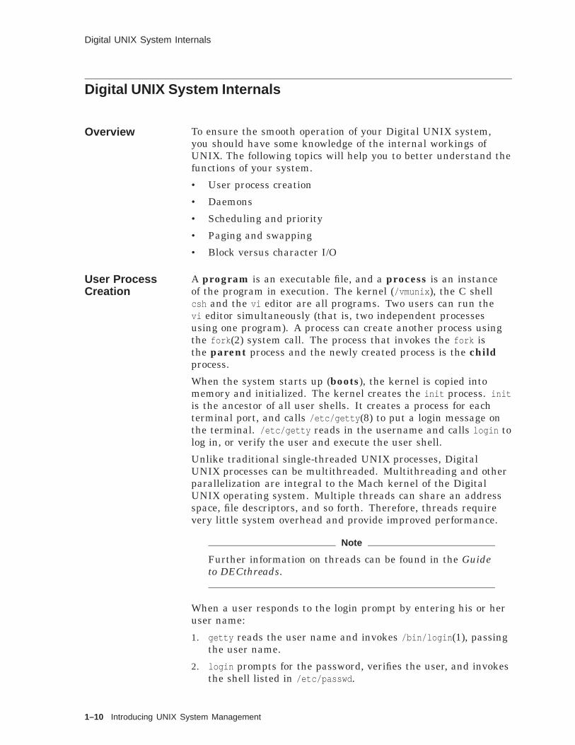
Digital UNIX System Internals
Digital UNIX System Internals
Overview To ensure the smooth operation of your Digital UNIX system,you should have some knowledge of the internal workings ofUNIX. The following topics will help you to better understand thefunctions of your system.
• User process creation
• Daemons
• Scheduling and priority
• Paging and swapping
• Block versus character I/O
User ProcessCreation
A program is an executable file, and a process is an instanceof the program in execution. The kernel (/vmunix ), the C shellcsh and the vi editor are all programs. Two users can run thevi editor simultaneously (that is, two independent processesusing one program). A process can create another process usingthe fork (2) system call. The process that invokes the fork isthe parent process and the newly created process is the childprocess.
When the system starts up (boots), the kernel is copied intomemory and initialized. The kernel creates the init process. initis the ancestor of all user shells. It creates a process for eachterminal port, and calls /etc/getty (8) to put a login message onthe terminal. /etc/getty reads in the username and calls login tolog in, or verify the user and execute the user shell.
Unlike traditional single-threaded UNIX processes, DigitalUNIX processes can be multithreaded. Multithreading and otherparallelization are integral to the Mach kernel of the DigitalUNIX operating system. Multiple threads can share an addressspace, file descriptors, and so forth. Therefore, threads requirevery little system overhead and provide improved performance.
Note
Further information on threads can be found in the Guideto DECthreads.
When a user responds to the login prompt by entering his or heruser name:
1. getty reads the user name and invokes /bin/login (1), passingthe user name.
2. login prompts for the password, verifies the user, and invokesthe shell listed in /etc/passwd .
1–10 Introducing UNIX System Management

Digital UNIX System Internals
3. The shell interprets all user commands.
When the user logs out, init updates the login history file/var/adm/wtmp and creates a new getty process listening on thatport.
The following figure illustrates the sequence of events for a userlogging in to the Digital UNIX system from a terminal.
Figure 1–3 Logging In to a Terminal
"program"
init
init getty login ksh
ksh
pid 2345pid 2345
exit()
exec()
wait() => 2345
exit()
exec()
fork()=2345
fork()=1234
pid 1 wait()=>1234
Terminal Login
ZKO−060000135−43−RGS
exit()exit()exit()
exec() exec()pid 1234pid 1234 pid 1234
DaemonProcesses
Another type of process is the daemon; daemon processes are notassociated with any users but perform system functions, such asprinter spooling, network control and time-dependent activities.Many daemons are started when the system boots.
ProcessEnvironment:Scheduling andPriority
UNIX is a timesharing system; it allows many processes to runat the same time.
The kernel identifies each process by a process number, orprocess ID (PID). Process 0 is a special process created whenthe system boots. init has process ID 1. Executing the ps -fcommand shows the user processes, their PIDs and their parents’PIDs, or PPIDs. You can see that each process has a parent, forexample tty4 (Korn shell process) is the parent of the telnetprocess. You can also see by following backwards the PPIDs thattty3 (Korn shell process) is the ancestor of the ftp process.
Introducing UNIX System Management 1–11

Digital UNIX System Internals
Figure 1–4 PID/PPID Numbers
On a time-sharing system, the kernel allocates the CPU toa process for a period of time, called a time slice, and thenswitches to another process. The switch is called a contextswitch. The kernel, which is executing in the context or theenvironment of a process, saves the state of the process andenough information about the process and what it was doing toresume later where it left off.
Every process has a scheduling priority. All processes start withsome base priority (in the range 0 to 63); lower numbers representhigher priority. System processes have higher priority than userprocesses. The kernel picks the process with the highest priorityto run next.
Users can lower the priority of their own processes. Thesuperuser can lower or raise the priority of processes. The systemalso adjusts priorities internally on a timesharing policy; a processthat is using CPU time has its priority lowered, while a processthat is waiting to run has its priority raised. This ensures that allwaiting processes will get their turn to run. The ps lax commandshows the user-adjusted priority (NICE column) and the systempriority (PRI column). The timesharing policy has the goal ofequitably sharing the processors among the various processes.
Digital UNIX also supports a fixed-priority policy, where the goalis to provide preferential treatment to particular processes. Forfixed-priority processes, the scheduler priority is equal to the basepriority.
1–12 Introducing UNIX System Management

Digital UNIX System Internals
Real TimeProcessing
A real-time process reacts to external events within a specifiedtime limit, and reacts in a predictable way. Real-time tasks canvary from process control for manufacturing to simulators forflight training.
Digital UNIX provides preemption and fixed-priority schedulingto support real-time processes. Preemption allows a highpriority process to take control of the CPU if it becomes runnablewhile a lower priority process is currently executing.
The real-time scheduling interface supports three policies thatgive the programmer the ability to select which class a processshould belong to:
• Timesharing - Standard Digital UNIX scheduling policy.Process priority is adjusted periodically by the kernel based onCPU usage and system load average.
• FIFO - Fixed priority first-in first-out policy. If no higherpriority process preempts, the process runs until itrelinquishes the CPU through a blocking call; there is noquantum time limit.
• Round-robin - Fixed-priority policy similar to FIFO, but addsa time quantum. A process must relinquish control of theCPU if it has used its quantum and another process of equalpriority is ready to run.
MemoryManagement:Paging andSwapping
The kernel is in main memory along with the currently executingprocess. However, physical memory is a limited resource;generally not all active processes can fit into memory. Disk spaceis used as a secondary memory managed by paging and swapping.The paging/swapping area is set up during system installationand can be resident on a local disk or in the case of disklessworkstations, on a disk available over the network.
Programs can be written larger than physical memory up to somemaximum size virtual memory. The hardware manipulatesprograms and data in lengths called pages. Special codetranslates the virtual memory page addresses to physicaladdresses. When the process tries to access data on a page notin physical memory, the kernel retrieves it from paging space ondisk and overwrites a page in memory.
The kernel keeps as many processes in physical memory as it canand lets each one execute during its time slice. (UNIX) swappingoccurs when a process needs to be loaded into memory to beexecuted, but there is no room for it. Another process is swappedout, or saved to the swap area on disk to free up memory.
Digital UNIX uses a slightly different notion of swapping. Aprocess may consist of multiple threads sharing an address space.Swapping out a thread’s address space would make the otherthreads in the same process unrunnable. The swapout daemonscans the list of all threads to identify those that have been idle
Introducing UNIX System Management 1–13

Digital UNIX System Internals
for more than 10 seconds. The pageout daemon can then free thememory pages associated with the thread’s kernel stack. The goalis still to free memory. And a thread must still be swapped inwhen it is made runnable.
Block versusCharacter I/O
When a process wants to access data from a file on a disk drive,the kernel brings the data into memory where the process canexamine it, alter it and ask to store or rewrite it.
Device drivers, or special code in the kernel controls theoperation of peripheral devices.
Mass storage devices such as disk drives are treated as block orcharacter devices. A block device is a random-access storagedevice. A memory buffer, called the buffer cache, is used to reada block of bytes to the device at one time. This technique canreduce the amount of disk traffic and improve response time ifprocesses tend to manipulate data within the same block. Onedisadvantage is that if the system halts suddenly, the updatedbuffer cache may not be written out to disk.
A character device, also called a raw device, does not use thebuffer.
A disk device can be treated as both a block and a raw device andhas a separate logical name for each.
1–14 Introducing UNIX System Management

Superuser and the Root Login
Superuser and the Root Login
SuperuserPrivileges
A UNIX system manager has special system privileges thatexceed those of ordinary users. For this reason, the systemmanager is called the superuser. UNIX systems reserve thelogin name root (user ID 0) for the superuser. Root owns andcontrols many important system files and directories.
As root, the superuser’s special system privileges include completeaccess to any file or directory as well as privilege to:
• Override all file mode permissions
• Bypass all normal security checks
• Kill any existing process
• Shut down the system
Root Security Root is a very powerful user, so powerful that a system managerwho carelessly uses its privileges can accidentally destroyan entire file system. Consequently, you should keep theroot password a secret, known only to you and one (or more)experienced backup person at your site. This person should havethe knowledge to perform system management responsibilities.To protect against potential superuser abuse, you should changethe root password regularly with the passwd command.
• Always log in as root using su because the system logs everyset user to root attempt in /var/adm/sialog .
• Perform nonprivileged commands as a nonprivileged user toprevent accidental system damage.
• You can log in directly as root only on terminals set up assecure in /etc/securettys .Network terminals or LAT terminals should not be set up assecure for security reasons.
Root LoginProcedure
While you can log in directly as root, the following is thesuggested login procedure:
1. Log in under your personal login name.
2. Use the su command to set user ID to root.
3. When you have successfully entered the root password, thesystem returns the superuser prompt (#).
4. Change to the root or other directory.
Press Ctrl/D to exit the root shell and return to your original shell.
Introducing UNIX System Management 1–15

Superuser and the Root Login
Root LoginRestrictions
Digital UNIX and many other UNIX systems restrict the directlogin as root to terminals flagged as secure in /etc/securettys(Base Level).
Some UNIX systems restrict the use of the su command (to setuser to root) to terminals flagged as su in /etc/securettys .
Digital UNIX systems restrict the use of the su command (to setuser to root) to members of group 0 (system group).
When someone uses the su command to set user to root, it islogged in the /var/adm/sialog file. If the file does not exist,the user must create it, for example using the commandtouch /var/adm/sialog .
Table 1–2 shows the logged messages for three different root loginattempts.
Table 1–2 Root Login Comparisons
Terminal Session Log Messages Description
Preferred Method
login: joePassword:$ suPassword:#
Successful authentication forsu from joe to root
User uses the su command to login as root.The system records thesuccessful set UID.
su Failure
login: joePassword:$ suPassword:Sorry$
Failure on authentication forsu from joe to root
User fails to enter the correctpassword.System refuses access as root.Record of unsuccessful set UID.
Less Secure Method
login: rootPassword:#
The system does not log amessage.Consequently, it is difficult todetermine who it is.
Check the log file /var/adm/sialog for authorized andunauthorized su attempts.
1–16 Introducing UNIX System Management

Common Desktop Environment
Common Desktop Environment
Managing withCDE
UNIX system management is made easier with the introduction ofthe Common Desktop Environment (CDE). CDE does not changethe basics of system management in terms of responsibilityor tasks to be performed. Rather it presents a window-likeenvironment to the system manager for performing managementtasks. Special system privileges that exceed those of ordinaryusers are still required (superuser). CDE can perform manymanagement tasks such as:
• Account management
• Print management
• Network management
• Disk management
• Archiving
• File system sharing
• Host management
• License management
• BIND
• NFS
• NIS setup
• System startup and shutdown
Front Panel CDE is entered automatically when the user logs in to aworkstation. Figure 1–5 shows the front panel, which providesthe window controls.
The major controls (left to right):
• File Manager - provides different views of system files
• Personal Applications - can be used to start up a terminalwindow or a text editor
• Workspace - virtual desktop; four are set up by default
• Exit - log out
• Style Manager - allows the user to select colors, fonts, screensaver and so forth
• Application Manager - contains the system managementapplications
Introducing UNIX System Management 1–17

Common Desktop Environment
Figure 1–5 Front Panel
Clock
Calendar
Personal Applications
File Manager Mailer Printer
Style Manager
Application Manager
Help Manager
Trash Can
Exit
Lock
Workspace switch
Busy light
Blank control
ZKOX−5256−202−RGS
Note
For a more thorough explanation of the features of CDE,refer to the Common Desktop Environment: Users Guide
ApplicationManager
This icon is used (MB1) to invoke the various system managementtasks which may be performed with or through the commondesktop environment. The figure shows the path used to get tothe System_Admin application.
1–18 Introducing UNIX System Management

Common Desktop Environment
Figure 1–6 System Management
Five main groups of tools are displayed:
• Configuration
• DailyAdmin
• MonitoringTuning
• Storage_Management
• Tools
Introducing UNIX System Management 1–19

Common Desktop Environment
ConfigurationManager
When the user or administrator selects the Configuration icon,the Application Manager - Configuration window is displayed.Each icon in the window represents a major configuration tool,which when selected brings the user to the actual managementoptions available.
Figure 1–7 Configuration Manager
1–20 Introducing UNIX System Management

Common Desktop Environment
DailyAdministration
Illustrated in the next figure are the tasks which may requiredaily attention such as adding or modifying a user account(Account Manager). File management is performed with theArchiver and File System Sharing tools. The License Manager isused to load software licenses. Shutdown allows the administratorto issue shutdown notices to users as well as select the shutdownand reboot characteristics. Hosts may be selected for remoteaccess to X Windows using the Host Manager.
Figure 1–8 DailyAdmin
Introducing UNIX System Management 1–21

Common Desktop Environment
SelectingSystemInformation
Selecting System Information yields status on system resourcessuch as CPU, Memory and so forth, as shown in the next figure.
Figure 1–9 System Information
1–22 Introducing UNIX System Management

Common Desktop Environment
Monitoring andTuning
These tools allow the administrator to view the status of thesystem and also fine tune the operation for either the kernel orthe processes on the system.
Figure 1–10 Monitoring and Tuning
Introducing UNIX System Management 1–23

Common Desktop Environment
StorageManagement
This management option provides controls for Digital added valuestorage system solutions.
Figure 1–11 Storage Management
The Bootable_Tape icon invokes the btcreate utility to build astandalone bootable kernel on UFS and AdvFS file systems.
The Logical Storage Manager icon starts the dxlsm utility tocreate and manage logical volumes (its use requires a license).
The Prestoserve I/O Accelerator can be used to display thedxpresto window to monitor the effectiveness of the cache. Cachestatistics such as:
• Writes/second
• Hits/second
may be observed. User controls are provided to vary the display.
1–24 Introducing UNIX System Management

Common Desktop Environment
Using Tools Here the administrator may select and display statisticalinformation on these topics.
• I/O
• Network
• Virtual Memory
• Who?
Figure 1–12 Tools
Introducing UNIX System Management 1–25

Summary
Summary
SystemManagerResponsibilities
The system manager is responsible for providing a workingcomputing environment for his users. This may include thefollowing tasks:
• Install and configure the system
• Shut down and start up the system
• Control user access
• Manage disk space
• Maintain archives of user and system files
• Monitor the system
• Troubleshoot the system
• Assist users
UNIX SoftwareEnvironment
An operating system is a dedicated computer program whoseprimary purpose is to execute other programs, managing thehardware and system resources for those programs.
The UNIX operating system consists of:
• Device drivers, special software to communicate withperipheral devices
• Kernel, the main part of the operating system, responsible forcontrolling system resources
• Other utilities and programs
Digital UNIXFeatures
The Digital UNIX operating system consists of:
• Symmetric Multiprocessing (SMP)
• Multithread Support
• Realtime Support
• Shared Libraries
• Memory Mapped Files
Digital UNIXSystemInternals
Some of the Digital UNIX system internal functions:
• A process is a program executing in memory.
• When the system boots, the kernel is copied into memory, andit starts init , which creates processes for all terminal ports.
• Daemons are system processes.
• Every process has a process ID and a priority.
• The kernel gives CPU time to the process with the highestpriority.
1–26 Introducing UNIX System Management

Summary
• Memory is divided into pages. The kernel uses a pagingtechnique to let a process use more memory than is physicallypresent.
• Managing more processes than fits into memory requiresswapping to free process memory to bring another process intomemory.
• Block I/O uses a buffer to read and write entire disk blocks ata time. Character or raw I/O does not use the buffer.
Superuser andRoot Login
UNIX system managers use the root login name (UID 0).
• root has special system privileges.
• To log in as root, first log in to your own account, then use thesu command.
CommonDesktopEnvironment
UNIX system management is made easier with the introduction ofthe Common Desktop Environment (CDE). CDE does not changethe basics of system management in terms of responsibilityor tasks to be performed. Rather it presents a window-likeenvironment to the system manager for performing managementtasks.
Introducing UNIX System Management 1–27

Exercises
Exercises
Superuser andthe root Login
1. Try the su command:
a. Find out the root password from your instructor.
b. If your system has the PAKs installed, and user accountcreated, log in under your personal login name and use thewhoami command.
c. Use the su command to switch to the root login. Be sure totype the root password correctly.
d. Try the whoami and who am i commands. Why is there adifference in the result?
e. Check the /var/adm/sialog file for the message thatdescribes your successful root login.
f. Log out as root.
2. Try the su command again, but this time type the rootpassword incorrectly. Find the message that describes yourunsuccessful root login.
CDE andSuperuser
1. Get the root password for your system from your instructor.
2. Log in as Root.
3. Create a user account for your lab team (SAxx - where xx isyour team number) using the CDE Account Manager.
4. Log out.
5. Log in as SAxx.
6. Invoke the Disk Manager.
Note
You need the root password. This is consistent with thesuperuser module for system management.
7. Record the number and type of disks on your system.
1–28 Introducing UNIX System Management

Solutions
Solutions
Superuser andthe root Login
1. Try the su command:
a. No solution required.b. login: sue
$ whoamisue$
c. $ suPassword:#
d. whoami prints your current login name; while who am iprints your login name from /var/adm/utmp .
# whoamiroot# who am itinker!sue ttyp1 May 26 08:18 (:0.0)#
e. # grep root /var/adm/sialogSuccessful authentication for su from sue to root
f. # Ctrl/D
$
2. Unsuccessful root login:
$ suPassword:Sorry$# grep root /var/adm/sialogSuccessful authentication for su from sue to rootFailure on authentication for su from sue to root
CDE andSuperuser
1. Get the root password for your system from your instructor.
2. Log in as Root.
3. Create a user account for your lab team (SAxx - where xx isyour team number) using the CDE Account Manager. You mayuse the ADD icon or choose New Local User from the Accountpull-down menu.
4. Log out.
5. Log in as SAxx.
6. Invoke the Disk Manager.Select the Disk icon from the Application Manager -Configuration window.
Introducing UNIX System Management 1–29

Solutions
7. Record the number and type of disks on your system.Select a disk from the Disk Configuration window.Click the Configure... button.Click the Cancel button to exit without making changes to therunning system disks.
1–30 Introducing UNIX System Management

2Managing Disks and File Systems
Managing Disks and File Systems 2–1

About This Chapter
About This Chapter
Introduction This chapter is an introduction to UNIX file systems. It illustratesthe parts of a physical disk and how the disk is organized logicallyto hold separate file systems. It describes the different types offile systems supported by Digital UNIX and the generic interface,the Virtual File System (VFS). It reviews the types of files andoverviews the organization of system files. It demonstrates how tochange partition sizes, create a file system, check the file system,and mount and dismount the file system.
Lab exercises provide practice using the disklabel , newfs , fsck ,mount , and umount commands.
The term sector means the fixed-size, hardware-oriented unit(generally 512 bytes) and block to represent the unit defined bythe file system (typically 1024, 4096 or 8192 bytes).
Objectives To manage UNIX file systems, you should be able to:
• Identify the various components of a disk drive
• Explain the concepts of logical volumes
• Explain the purpose and contents of the logical disk partitions
• View and change partition sizes using CDE
• View and change partition sizes
• Explain the organization and advantages of the various filesystems
• Describe the organization of system files
• Describe the Advanced File System
• Create a new file system
• Check a file system’s consistency
• Mount and unmount a file system
Resources For more information on the topics in this chapter, see thefollowing:
• Nemeth, Snyder, & Seebass, (c) 1989, UNIX SystemAdministration Handbook, Prentice-Hall, ISBN 0-13-933441-6,Chapters 4 and 12
• Digital UNIX System Administration, Chapter 7
• Leffler, McKusick, Karels, and Quarterman, (c) 1989, TheDesign and Implementation of the 4.3BSD UNIX OperatingSystem, Addison-Wesley, ISBN 0-201-06196-1, Chapter 7describes the UNIX file system
2–2 Managing Disks and File Systems
About This Chapter
• POLYCENTER Advanced File System Technical Summary
• ULTRIX to DEC OSF/1 Migration Guide, describes the filesystems and directory structure
• Marshall Kirk McKusick, "Fsck - The UNIX File SystemCheck Program" in UNIX Supplementary Documents
Managing Disks and File Systems 2–3

Disk Drives
Disk Drives
Disk DriveStructure
Each circular plate is called a platter. The top and bottomsurfaces in the stack are not generally used.
Disk capacity can be enlarged by increasing the:
• Size of the platter (this increases seek time and reducesperformance)
• Number of platters in the stack
• Density at which information is written
Figure 2–1 Disk Drive Structure
SECTOR
TRACKSURFACE
CYLINDERHEADS
G S F _ 0 6 9 8 _ 8 9 . D G
Surfaces • Top and bottom of a disk platter
• Coated with a magnetic material
2–4 Managing Disks and File Systems

Disk Drives
Heads • Perform read and write on disk surface
• One head per surface
• Mounted inline vertically on a movable arm
Tracks • Concentric circles as traced by a head on a continuouslyrotating surface.
• Many tracks can be formed on a single surface.
Cylinders Cylinders are imaginary figures formed by dropping a top surfacetrack down through the tracks directly below on all surfaces.
All sectors on all recording surfaces are located at the samedistance from the center spindle of the disk.
Cylinder zero (0) includes:
• Track 0, surface 0
• Track 0, surface 1
• Track 0, surface 2
• Track 0, surface 3
• And so forth
A cylinder group is a set of contiguous cylinders.
Sectors A sector is the smallest contiguous region on a disk that may beaccessed with a single I/O operation.
A sector is addressed by its logical block number (LBN).
• All surfaces are divided into pie slices.
• Each portion of a single track inside one pie slice is a sector.
• There are 512 bytes of information per sector.
Disk Operation The disk rotates at a high rate of speed. The heads are mountedon arms that move in and out from the center. The heads hoververy close to the surface without touching it. If a head does touchthe surface, this is a head crash and can destroy the surface ofthe platter.
To read or write a block of data, the head seeks, or moves to thecorrect track, and the driver waits until the correct sector rotatesunderneath the head.
Managing Disks and File Systems 2–5

Logical Volumes
Logical Volumes
Overview Logical volumes add a level of abstraction between the physicaldisk devices and the file system.
Logical volumes can be implemented at several different layers:
• Hardware
RAID devices (HSZ10/15, HSZ20/40) - several physicaldisks are seen as one unit
• Device driver
Partition - a group of contiguous cylinders on one physicaldisk is seen as one unit
Logical Storage Manager (LSM) - several physical disks orpartitions from several disks are seen as one unit
Note
The hardware and driver implementations are file systemindependent; you can put any file system on a logical unit.
• File system
POLYCENTER Advanced File System (AdvFS) - severalphysical disks or partitions are seen as one unit
The following figure shows the functional layering of components.A configuration can use any combination of the logical volumeimplementations.
2–6 Managing Disks and File Systems

Logical Volumes
Figure 2–2 Functional View of Logical Volumes
Disk Disk RAID Device
File Systems
Disk Device Drivers
Logical Volume Driver
UFS AdvFS
ZKOX−2037−20−RGS
Managing Disks and File Systems 2–7

Partitions and File Systems
Partitions and File Systems
Disk Partitions For better performance for access, UNIX systems divide disks intochunks called partitions, known by letters a through h. Somedisks have fewer than eight partitions.
Partitions are groups of sectors, which means they are sized inmultiples of 512 bytes.
One possible configuration of our example disk is:
• Partition a - Root file system
• Partition b - Swapping/paging areaSwapping/paging space is used when there is not enoughroom in physical memory for user programs or data. Someinformation is copied from memory to the swap area, to freeup memory for other information.
• Partition g - /usr directory
Every UNIX file system is located within a logical volume, suchas a partition. Disks can have more than one file system, but onlyone UNIX file system can exist on a partition. You should not useoverlapping partitions for a file system.
Remember, a partition is a logical division of a disk.
Partitions on aDisk
The following figure shows overlapping partitions on a disk.
Figure 2–3 Overlapping Disk Partitions
Physical Disk
c
a b g
d e f ZKO−060000135−11−RGS
HierarchicalFile Systems
A file system is a hierarchical structure consisting of directoriesand files. For example, partition a on the system disk contains:
• Root file system (/ )
• Such directories as /dev and /etc
2–8 Managing Disks and File Systems
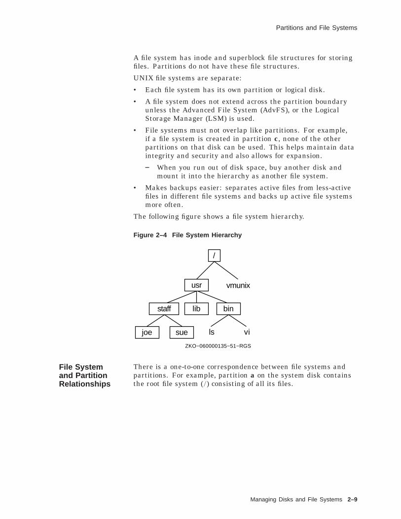
Partitions and File Systems
A file system has inode and superblock file structures for storingfiles. Partitions do not have these file structures.
UNIX file systems are separate:
• Each file system has its own partition or logical disk.
• A file system does not extend across the partition boundaryunless the Advanced File System (AdvFS), or the LogicalStorage Manager (LSM) is used.
• File systems must not overlap like partitions. For example,if a file system is created in partition c, none of the otherpartitions on that disk can be used. This helps maintain dataintegrity and security and also allows for expansion.
When you run out of disk space, buy another disk andmount it into the hierarchy as another file system.
• Makes backups easier: separates active files from less-activefiles in different file systems and backs up active file systemsmore often.
The following figure shows a file system hierarchy.
Figure 2–4 File System Hierarchy
/
usr vmunix
staff lib bin
joe sue ls vi
ZKO−060000135−51−RGS
File Systemand PartitionRelationships
There is a one-to-one correspondence between file systems andpartitions. For example, partition a on the system disk containsthe root file system (/ ) consisting of all its files.
Managing Disks and File Systems 2–9

Partitions and File Systems
Example 2–1 Root Directory
$ ls -F /bin@ genvmunix* lost+found/ osf_boot* tmp/ vmunix*dev/ home/ mnt/ sbin/ usr/etc/ lib@ opt/ sys@ var@
• File systems are separate and distinct.
• A file system does not extend across a partition boundary,unless the system uses logical volumes to create logicalvolumes.
• File systems must not overlap.
• File systems are created with the newfs (8) command.
• To make a file system on a partition visible in the directoryhierarchy and available to users, mount the file system.
Partition Tablesand DiskLabels
The disk device driver needs to know the partition sizes for eachdisk. It treats each partition as though it were a separate diskdrive.
Early versions of UNIX had tables defining partition locations andsizes compiled into the driver. More recent versions of BSD UNIXmoved the partition table information into a text file,/etc/disktab . ULTRIX /etc/disktab includes the disk geometryand default partition sizes, but not the partition offsets.
Digital UNIX puts partition information into a disk label in sectornumber LABELSECTOR of the disk, usually sector 0. The label isused by the disk device driver and boot program to recognize thedrive and partitions. If a disk is not labeled, partition informationis obtained from /etc/disktab .
Example 2–2 shows a sample /etc/disktab file.
Digital UNIX recognizes partition tables created by earlier DigitalUNIX and DEC OSF/1 releases and ULTRIX systems.
Deriving DiskParameterswith/etc/disktab
The /etc/disktab file is a simple database that describes diskgeometries and disk partition characteristics (patterned after thetermcap terminal database). Fields are separated by a colon (:)and disk names (first field) are separated by a vertical line ( | ).
The following table shows the layout of the partitions for an RZ23Winchester disk.
Partition Offset Size (sectors)Block Size(bytes)
FragmentSize (bytes)
a 0 131072 8192 1024
b 131072 262144 8192 1024
c 0 1299174 8192 1024
2–10 Managing Disks and File Systems
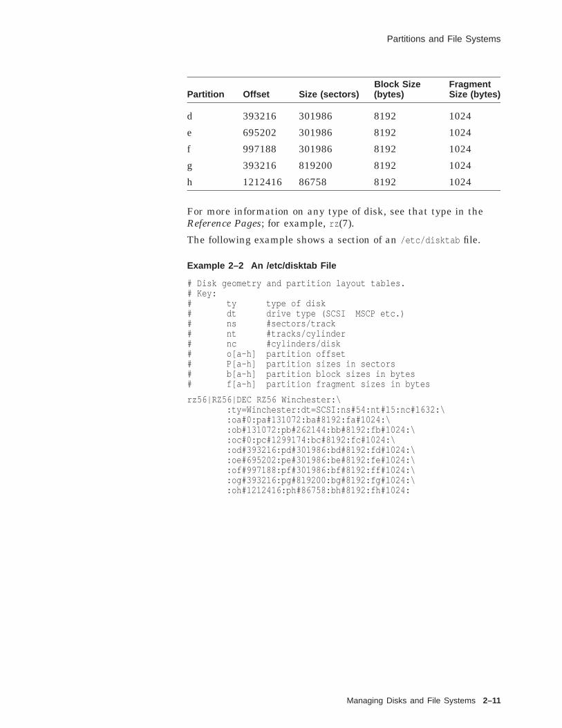
Partitions and File Systems
Partition Offset Size (sectors)Block Size(bytes)
FragmentSize (bytes)
d 393216 301986 8192 1024
e 695202 301986 8192 1024
f 997188 301986 8192 1024
g 393216 819200 8192 1024
h 1212416 86758 8192 1024
For more information on any type of disk, see that type in theReference Pages; for example, rz (7).
The following example shows a section of an /etc/disktab file.
Example 2–2 An /etc/disktab File
# Disk geometry and partition layout tables.# Key:# ty type of disk# dt drive type (SCSI MSCP etc.)# ns #sectors/track# nt #tracks/cylinder# nc #cylinders/disk# o[a-h] partition offset# P[a-h] partition sizes in sectors# b[a-h] partition block sizes in bytes# f[a-h] partition fragment sizes in bytes
rz56|RZ56|DEC RZ56 Winchester:\:ty=Winchester:dt=SCSI:ns#54:nt#15:nc#1632:\:oa#0:pa#131072:ba#8192:fa#1024:\:ob#131072:pb#262144:bb#8192:fb#1024:\:oc#0:pc#1299174:bc#8192:fc#1024:\:od#393216:pd#301986:bd#8192:fd#1024:\:oe#695202:pe#301986:be#8192:fe#1024:\:of#997188:pf#301986:bf#8192:ff#1024:\:og#393216:pg#819200:bg#8192:fg#1024:\:oh#1212416:ph#86758:bh#8192:fh#1024:
Managing Disks and File Systems 2–11

Viewing and Changing Partition Sizes with CDE
Viewing and Changing Partition Sizes with CDE
Overview In general, you change the partitions during the initialinstallation or when your file system is running out of space.
The CDE Disk Manager is available during system installation.
Note
The disklabel command is available in the Digital UNIXstandalone environment.
Displayingthe CurrentPartition Sizes
To display the current partition sizes, begin at the CDE FrontPanel and select the Application Manager icon.
Figure 2–5 Navigating to the Disk Configuration Window
2–12 Managing Disks and File Systems

Viewing and Changing Partition Sizes with CDE
The three Pop-up windows shown will be individually displayedas the user selects (double-clicks MB1) each of the options.
• System_Management_Utilities
• Configuration
• Disk
The Disk Configuration Pop-up window is displayed with the listof available disk devices on the system. Click the desired diskand then the Configure... button.
Figure 2–6 Disk Configuration
Managing Disks and File Systems 2–13
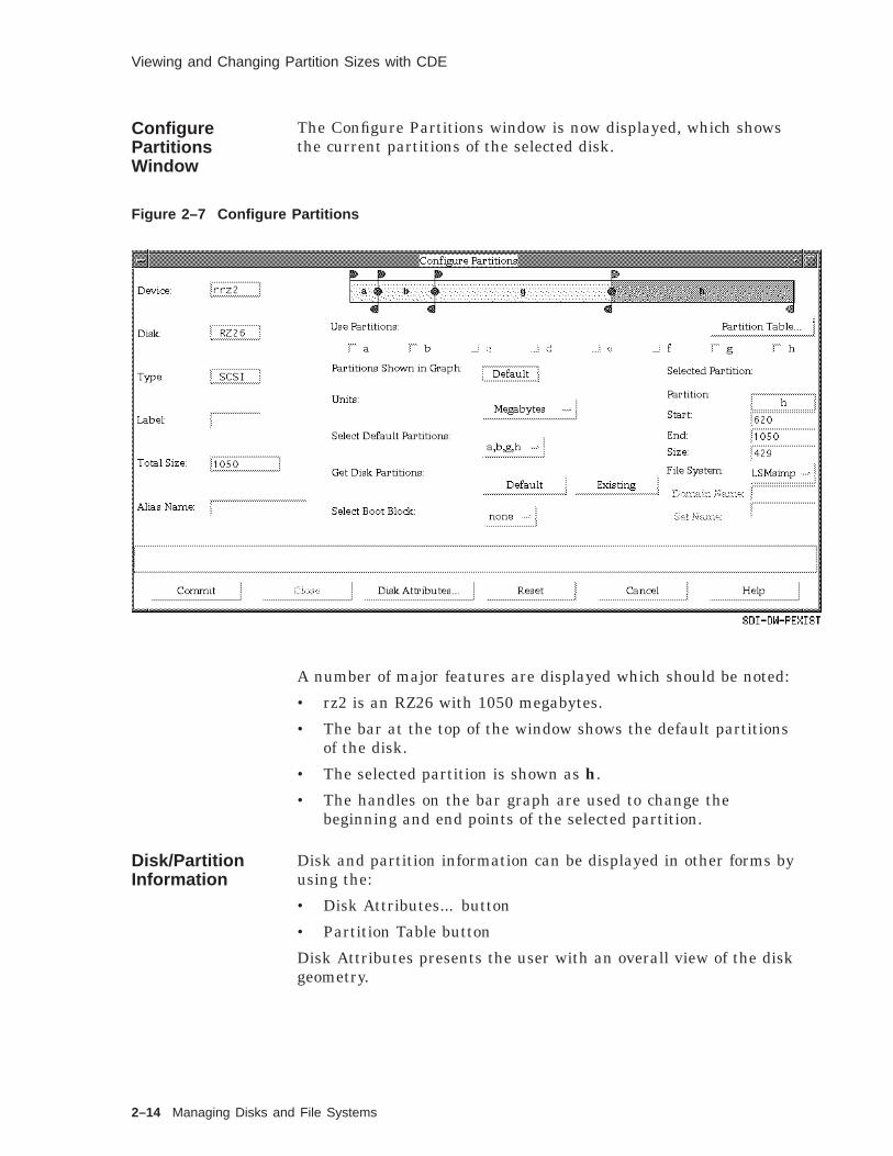
Viewing and Changing Partition Sizes with CDE
ConfigurePartitionsWindow
The Configure Partitions window is now displayed, which showsthe current partitions of the selected disk.
Figure 2–7 Configure Partitions
A number of major features are displayed which should be noted:
• rz2 is an RZ26 with 1050 megabytes.
• The bar at the top of the window shows the default partitionsof the disk.
• The selected partition is shown as h.
• The handles on the bar graph are used to change thebeginning and end points of the selected partition.
Disk/PartitionInformation
Disk and partition information can be displayed in other forms byusing the:
• Disk Attributes... button
• Partition Table button
Disk Attributes presents the user with an overall view of the diskgeometry.
2–14 Managing Disks and File Systems

Viewing and Changing Partition Sizes with CDE
Figure 2–8 Disk Geometry
Clicking the Partition Table button will display the followingwindow, which presents all the allowable partitions on the disk.
Managing Disks and File Systems 2–15

Viewing and Changing Partition Sizes with CDE
Figure 2–9 Partition Table
The full partition table displayed from two points of view.Partitions a, b, and h are highlighted by the bold box whichindicates these partitions are in use. All other partitions aredisplayed without highlighting, which signifies they are allowablebased on the defaults for the type of disk.
Note
Appendix F of the Digital UNIX Installation Guidecontains extensive information on the default partitionssupported for Digital Storage Architecture (DSA) andSmall Computer System Interface (SCSI) disks.
In this case the table is based on the disk type we selected, anRZ26. Based on the table information, we see that no otherpartition can be configured since all the disk space is in use.
These two displays allow the user to easily determine thecharacteristics of the device prior to implementing a change in theorganization of the device.
2–16 Managing Disks and File Systems

Viewing and Changing Partition Sizes with CDE
Modifying aPartition
Assume that we make a command decision to alter the partitionson the disk to accommodate another file system which is tosupport a specific application. Furthermore, the applicationrequires 365M bytes of longterm storage which we will allocate topartition g.
From a procedural point of view, we first select the defaultpartitions labeled a,b,g,h to set up the table, as seen in thefollowing figure.
Figure 2–10 Partition Size
The partition bar now shows that partitions g and h appear to besimilar in size. In fact, a quick check of the Selected Partition:h shows that its size is 429. But what is the unit of measure?An examination of the Units: field shows the unit of measure isMegabytes - , therefore it is a 429M byte partition.
The size of the g partition may be examined by simply clickingthe appropriate area on the partition bar. You can determine thatthis partition is also a 429M byte partition.
Note
Up until this point, nothing on the disk has been changed.
Verify that the changes are accurate and then click the Commitbutton. This action will write the new changes onto the disklabel.
Managing Disks and File Systems 2–17

Viewing and Changing Partition Sizes with CDE
The last action remaining is to choose the file system type for thenew partition using the File System selection button.
ChangingPartition Size
If a custom size partition is required, the user can resize thepartitions by using the bar graph.
Figure 2–11 Partition Bar Graph
Note that there are 10 flags on the bar graph beginning on thetop left of partition a. These are the handles used to grab andresize each partition.
• Top handles are for the left boundary.
• Middle handles move both boundaries of adjoining partitions.
• Bottom handles are for the right boundary.
The circular objects between the handles denote that twopartitions are adjacent to each other. Also note the gap (nocircular object) between partition g and h; indicating a gap on thedisk between partitions.
Use the following actions to customize any partition:
• Click and drag MB1 on top handles to move the left boundary.
• Click and drag MB1 on bottom handles to move the rightboundary.
2–18 Managing Disks and File Systems
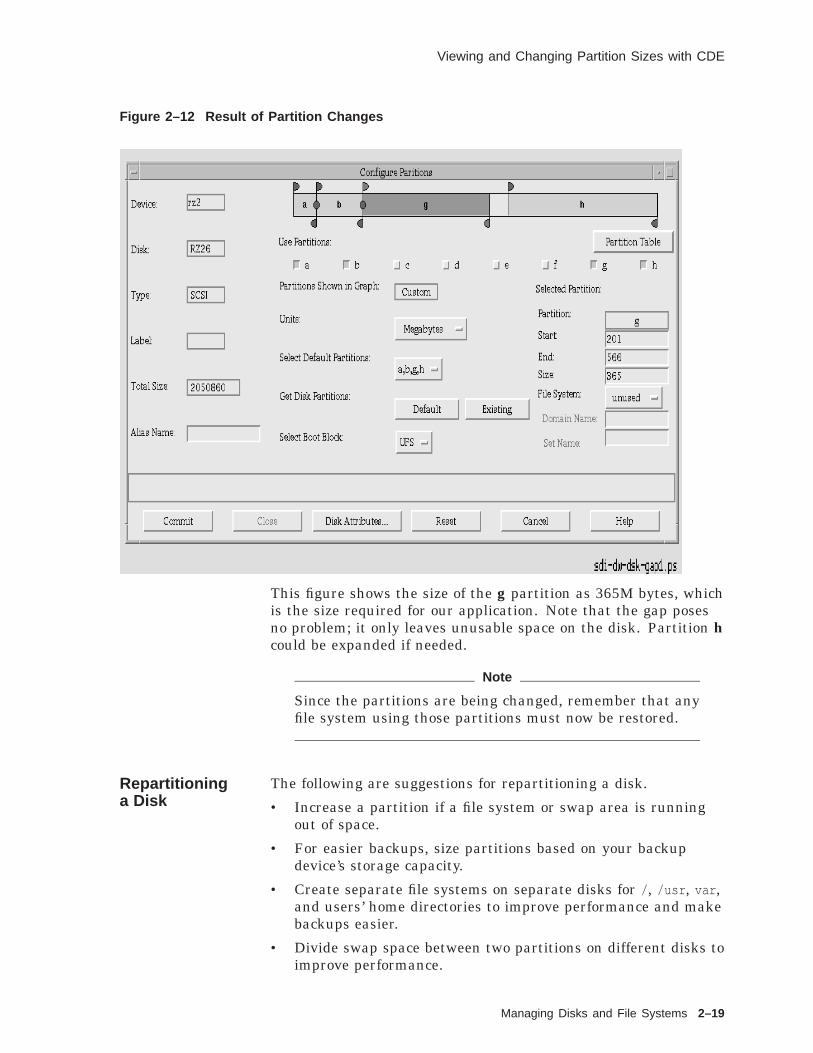
Viewing and Changing Partition Sizes with CDE
Figure 2–12 Result of Partition Changes
This figure shows the size of the g partition as 365M bytes, whichis the size required for our application. Note that the gap posesno problem; it only leaves unusable space on the disk. Partition hcould be expanded if needed.
Note
Since the partitions are being changed, remember that anyfile system using those partitions must now be restored.
Repartitioninga Disk
The following are suggestions for repartitioning a disk.
• Increase a partition if a file system or swap area is runningout of space.
• For easier backups, size partitions based on your backupdevice’s storage capacity.
• Create separate file systems on separate disks for / , /usr , var ,and users’ home directories to improve performance and makebackups easier.
• Divide swap space between two partitions on different disks toimprove performance.
Managing Disks and File Systems 2–19

Viewing and Changing Partition Sizes
Viewing and Changing Partition Sizes
Overview In general, you change the partitions during the initialinstallation or when your file system is running out of space.
The disklabel command is available in the Digital UNIXstandalone environment. You must have superuser privileges touse the disklabel command.
The partition size and offset are in 512-byte sectors. The offset isthe starting sector number for the partition.
To display the current partition sizes, use disklabel -r with theraw device name for partition a or c. The example shows how todisplay a disk label.
Example 2–3 Displaying the Disk Label
# disklabel -r /dev/rrz0a# /dev/rrz0a:type: SCSI 1disk: rz55 2label: 3flags: 4bytes/sector: 512 5sectors/track: 36tracks/cylinder: 15sectors/cylinder: 540cylinders: 1224rpm: 3600 6interleave: 1trackskew: 0cylinderskew: 0headswitch: 0 # millisecondstrack-to-track seek: 0 # millisecondsdrivedata: 0 7
7 partitions: 8# size offset fstype [fsize bsize cpg]
a: 40960 0 4.2BSD 1024 8192 16 # (Cyl. 0 - 75*)b: 122880 40960 4.2BSD 1024 8192 16 # (Cyl. 75*- 303*)c: 649040 0 unused 1024 8192 # (Cyl. 0 - 1201*)d: 152446 163840 unused 1024 8192 # (Cyl. 303*- 585*)e: 152446 316286 unused 1024 8192 # (Cyl. 585*- 868*)f: 180308 468732 unused 1024 8192 # (Cyl. 868*- 1201*)g: 485200 163840 4.2BSD 1024 8192 16 # (Cyl. 303*- 1201*)
#
1 Controller type; for example, SCSI, ESDI, SMD, MSCP
2 Disk type name
3 Optional label
4 Flags; for example, removable, RAMDISK, ECC
5 Disk geometry section
2–20 Managing Disks and File Systems

Viewing and Changing Partition Sizes
6 Hardware characteristics section
• Rotational speed in revolutions per minute.
• Sector interleave compensates for a slow controller;specified as the denominator of the ratio (sectors read/sectors passed over). Therefore an interleave of 1 (ratio1/1) implies contiguous layout, while 2 (ratio 1/2) implieslogical sector numbering is every other sector.
• Other skew techniques compensate for a slow controller; 0implies no skew.
• trackskew is the offset of sector 0 on track N relative tosector 0 on track N+1.
• cylinderskew is the offset of sector 0 on cylinder N relativeto sector 0 on cylinder N+1.
7 Drive type specific data (if any)
8 Partition table
• Partition name
• Partition size in sectors
• Starting sector number
• File system type; for example, unused, swap, 4.2BSD, ufs,raw, AdvFS, LSMpubl, database
• Fragment size in bytes
• Block size in bytes
• Cylinders per group
• Cylinder numbers
If your disk does not have a label, you will get a message such as:
# disklabel -r /dev/rrz2aBad pack magic number (label is damaged, or pack is unlabeled)
ChangingPartition Sizes
You might change your partition sizes when:
• A file system is running out of space
• Before doing a software installation, when your planningindicates you need more space
To change partition sizes:
1. Use df to determine if a partition is too large or too small andwhich other partitions on that disk are being used.
2. Back up all affected file systems.
3. Unmount the file systems on the disk whose label you want tochange.
4. Display the current partition sizes and calculate the new sizesand offsets.
Managing Disks and File Systems 2–21

Viewing and Changing Partition Sizes
5. Use disklabel -e -r to edit the disk label. Display the newpartition sizes.
6. Use newfs to create a file system on the partition and fsck tocheck it.
7. Mount the file system, restore files to it, and use it.
8. Backup the disk label information to a file using a commandsimilar to the following:disklabel -r rz0 > /usr/label_rz0
If necessary, you can restore the disk label using this file.
If the disk does not have any file systems on it (that is, a newdisk), write a default label using disklabel -w -r disk disktypeand start with Step 4.
To expand partition a from 40960 to 49152 sectors, for example,we must increase the offset and decrease the size of partition b by49152-40960=8192 sectors.
The disklabel -e command invokes the editor specified by theEDITOR environment variable or the vi editor. The -r optionaffects the disk label on the disk, rather than the copy in memory.
Be aware that the vi editor is not available when you bootto single user mode or work in the Digital UNIX standaloneenvironment.
Expanding aPartition
For example, we want to increase partition a on an RZ23 disk toinclude all of partition b so we can divide the disk into partitionsa and g. Note: in the following example, partition b is not beingused.
Figure 2–13 Expanding a Partition
Before0 40960 99458
a b g
After0 99458
a g
ZKOX−055000111−04−RGS
The following example shows how to change partition sizes.
2–22 Managing Disks and File Systems

Viewing and Changing Partition Sizes
Example 2–4 Expanding a Partition
# /sbin/disklabel -r /dev/rrz2a# /dev/rrz2a:type: SCSIdisk: rz23label:
.
.
.
8 partitions:# size offset fstype [fsize bsize cpg]
a: 40960 0 unused 1024 8192 # (Cyl. 0 - 155*)b: 58498 40960 unused 1024 8192 # (Cyl. 155*- 376*)c: 204864 0 unused 1024 8192 # (Cyl. 0 - 775)d: 35135 99458 unused 1024 8192 # (Cyl. 376*- 509*)e: 35135 134593 unused 1024 8192 # (Cyl. 509*- 642*)f: 35136 169728 unused 1024 8192 # (Cyl. 642*- 775*)g: 105406 99458 unused 1024 8192 # (Cyl. 376*- 775*)h: 70271 134593 unused 1024 8192 # (Cyl. 509*- 775*)
# /sbin/disklabel -e -r /dev/rrz2a(invokes an editor; we change partition a size from 40960 to 99458)
type: SCSIdisk: rz23label:flags:bytes/sector: 512sectors/track: 33tracks/cylinder: 8sectors/cylinder: 264cylinders: 776rpm: 3600interleave: 1trackskew: 0cylinderskew: 0headswitch: 0 # millisecondstrack-to-track seek: 0 # millisecondsdrivedata: 0
8 partitions:# size offset fstype [fsize bsize cpg]
a: 99458 0 unused 1024 8192 # (Cyl. 0 - 155*)b: 58498 40960 unused 1024 8192 # (Cyl. 155*- 376*)c: 204864 0 unused 1024 8192 # (Cyl. 0 - 775)d: 35135 99458 unused 1024 8192 # (Cyl. 376*- 509*)e: 35135 134593 unused 1024 8192 # (Cyl. 509*- 642*)f: 35136 169728 unused 1024 8192 # (Cyl. 642*- 775*)g: 105406 99458 unused 1024 8192 # (Cyl. 376*- 775*)h: 70271 134593 unused 1024 8192 # (Cyl. 509*- 775*)
~(when you exit the editor, you will be prompted)write new label? [y]: Return
(continued on next page)
Managing Disks and File Systems 2–23

Viewing and Changing Partition Sizes
Example 2–4 (Cont.) Expanding a Partition
# /sbin/disklabel -r /dev/rrz2a# /dev/rrz2a:type: SCSIdisk: rz23label:
.
.
.
8 partitions:# size offset fstype [fsize bsize cpg]
a: 99458 0 unused 1024 8192 # (Cyl. 0 - 376*)b: 58498 40960 unused 1024 8192 # (Cyl. 155*- 376*)c: 204864 0 unused 1024 8192 # (Cyl. 0 - 775)d: 35135 99458 unused 1024 8192 # (Cyl. 376*- 509*)e: 35135 134593 unused 1024 8192 # (Cyl. 509*- 642*)f: 35136 169728 unused 1024 8192 # (Cyl. 642*- 775*)g: 105406 99458 unused 1024 8192 # (Cyl. 376*- 775*)h: 70271 134593 unused 1024 8192 # (Cyl. 509*- 775*)
We can display the disk label again, showing the changes we havemade. Notice the cylinder numbers for partition a have beenautomatically updated.
Repartitioninga Disk
The following are suggestions for repartitioning a disk.
• Increase a partition if a file system or swap area is runningout of space.
• To make backups easier, size partitions based on your backupdevice’s storage capacity.
• Create separate file systems on separate disks for / , /usr , var ,and users’ home directories to improve performance and makebackups easier.
• Divide swap space between two partitions on different disks toimprove performance.
2–24 Managing Disks and File Systems

Digital UNIX File Systems
Digital UNIX File Systems
Overview The Digital UNIX operating system supports the following typesof file systems:
• UNIX file system (UFS)
• Network File System (NFS)
• Memory File System (MFS)
• Compact disk file system (CDFS) (ISO 9660)
• POLYCENTER Advanced File System (AdvFS)
• File on File Mounting File System (FFM)
• /proc File System
• /dev/fd File System (FDFS)
The CDFS file system also supports CD–ROMs recorded usingRock Ridge Interchange Protocol R1.09. The AdvFS is a local filesystem that uses journaling to recover from unplanned systemrestarts. The FFM file system allows regular, character, orblock-special files to be mounted over regular file systems, and isprimarily used on the SVR4-compatible system.
These operating systems support multiple types of file systems byusing a Virtual File System:
• VFS provides file system independent support for system calls.
• Different file system types are not apparent to the generaluser.
The following figure illustrates the virtual file system interfaceproviding access to other file systems.
Figure 2–14 File System Interface
ZKO−055−000147−124−RGS
VFS
UFS AdvFS NFS CDFS
Virtual FileSystem
To support different file system types, Digital UNIX includes ageneralized set of file system data structures as an interface calledthe virtual file system (VFS). The VFS layer provides supportfor system calls and dispatches the calls to the appropriate filesystem.
Managing Disks and File Systems 2–25
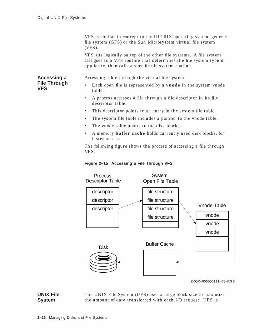
Digital UNIX File Systems
VFS is similar in concept to the ULTRIX operating system genericfile system (GFS) or the Sun Microsystem virtual file system(VFS).
VFS sits logically on top of the other file systems. A file systemcall goes to a VFS routine that determines the file system type itapplies to, then calls a specific file system routine.
Accessing aFile ThroughVFS
Accessing a file through the virtual file system:
• Each open file is represented by a vnode in the system vnodetable.
• A process accesses a file through a file descriptor in its filedescriptor table.
• This descriptor points to an entry in the system file table.
• The system file table includes a pointer to the vnode table.
• The vnode table points to the disk blocks.
• A memory buffer cache holds currently used disk blocks, forfaster access.
The following figure shows the process of accessing a file throughVFS.
Figure 2–15 Accessing a File Through VFS
ZKOX−055000111−05−RGS
ProcessDescriptor Table
SystemOpen File Table
Vnode Table
Buffer CacheDisk
descriptor file structure
vnode
descriptor
descriptor
vnode
vnode
file structure
file structure
file structure
UNIX FileSystem
The UNIX File System (UFS) uses a large block size to maximizethe amount of data transferred with each I/O request. UFS is
2–26 Managing Disks and File Systems

Digital UNIX File Systems
also known as the Berkeley fast file system, developed by theUniversity of California at Berkeley.
• File names can contain up to 255 characters.
• The goal is to lay out files for fast access and minimal waste ofspace.
Uses a large block size (4096 or 8192 bytes) to maximizedata transfer
Allows blocks to be split into fragments to reduce wastedspace
There are two differences between UFS and System V:
• Use of blocks and fragments
• Changed file system layout using cylinder groups
Figure 2–16 Small Blocks Require More Overhead
FILE 1
FILE 2
X X X X X X X X
X
ZKO−RA0188−11−RGS
Figure 2–17 Large Blocks Waste Space
FILE 1
FILE 2
X X X X X X X X
X
ZKO−RA0188−12−RGS
Figure 2–18 Large Blocks and Small Fragments
FILE 1
FILE 2
X X X X X X X X
X
ZKO−RA0188−13−RGS
In the first two figures, we see file systems with only one blocksize, no fragment size. A small block size requires more overheadand more time to handle large files. A large block size wastesspace when files are small.
Managing Disks and File Systems 2–27

Digital UNIX File Systems
4.3BSD, ULTRIX, and Digital UNIX file systems allow a blockto be divided into smaller pieces called fragments. The defaultfragment size is typically 1K byte. When disk space is needed,either a block or a fragment can be allocated.
Note
If a file is > 96K bytes, the system does not bother toallocate a fragment; it assumes the file will grow larger, soit allocates a full block.
Block and fragment sizes are specified when the file systemis created. The defaults can be seen in the disk label or /etc/disktab .
Many units in the file system are measured in fragments ratherthan blocks.
For the layout policies to be effective, the file system cannot bekept completely full. Each file system maintains a parameter(minfree ) for the minimum percentage of file system blocks thatcan be free. Below this threshold, only the superuser can allocateblocks. Reducing this percentage may hurt performance in a filesystem that is actively allocating and freeing blocks.
UNIX FileSystem Layout
Cylinder groups require more overhead for storing extra structure,but the gain in performance is worth it.
The superblock is replicated in a different position in eachcylinder group to prevent loss of critical data in case an entirecylinder or surface is damaged.
The following figure illustrates the UNIX file system layout.
Figure 2–19 UNIX File System Layout
Partition
Cylinder Group 0 Cylinder Group N
ZKO−060000135−13−RGS
BootBlock
SuperBlock
AlternateSuperBlock
AlternateSuperBlock
CylinderGroupBlock
CylinderGroupBlock
InodeTable
InodeTable
Data DataData
MFS FileSystem
The mfs command builds a Memory File System (MFS), which is aUFS file system in virtual memory, and mounts it on the specifiedmount-node. When the file system is unmounted, MFS exits andthe contents of the file system are lost. If MFS is sent a signal
2–28 Managing Disks and File Systems

Digital UNIX File Systems
while running, for example during system shutdown, it attemptsto unmount its corresponding file system.
For a memory file system, the special-device file provides only aset of configuration parameters, including the size of the virtualmemory segment to allocate. If the special-device file is omitted,you must specify the segment size. The special-device file isusually the primary swap area, because that is where the filesystem is backed up when free memory gets low and the memorysupporting the file system has to be paged.
You can enable /tmp as a memory file system by adding an entryin the /etc/fstab file. For example, the following line creates a 10Megabyte memory file system, mounted on /tmp :
-s20480 /tmp mfs rw 1 0
Note that the contents of a memory file system are lost whenevera reboot or unmount is performed.
You must be superuser to use this command.
Note
Refer to the man page on MFS for further information.
Network FileSystem
Network File System (NFS) is a service that allows you to mountdirectories across the network and treat those directories as ifthey were local.
NFS is a facility for sharing files in a heterogeneous environmentof processors, operating systems and networks. Sharing isaccomplished by mounting a remote file system or directory on alocal system and then reading or writing files as though they werelocal.
Exporting file systems consists of creating an /etc/exports (5nfs)file that lists directories that other systems have permission toaccess.
The exporting system, or server, plays a passive role in filesharing. The system that imports a file system, the client, canmount that file system at any point within its local file system.Imported file systems are not copied to the client’s own file systembut are accessed transparently using remote procedure calls.Imported file systems appear to a client system user as local files.
The following figure shows system Cabala importing twodirectories from system Cherub.
Managing Disks and File Systems 2–29

Digital UNIX File Systems
Figure 2–20 Remote Mounting with NFS
/
bin usr etc
cherub
man
man1 ... man8
file1 file2
cabala (Client)
/
bin usr etc
project
man
man1 ... man8
file1 file2
cherub (Server)
ZKOX−055000111−19−RGS
share share
A system that acts as a server can also act as a client. A serverthat exports file systems can also mount remote file systemsexported by other systems, therefore becoming a client.
Compact DiskFile System
Digital UNIX systems support the compact disk, read-onlymemory file system, CDFS, based on the international standardISO 9660-1988. Volumes recorded in the ISO 9660-1988(interchange level 2) or High Sierra Group (HSG) format can bemounted for reading. CDFS is a configurable kernel option. Seecdfs (4) and mount (8cdfs) for more information.
Mount options for CDFS:
defperm Ignores permission bits specified on the disk anduses value 0666 with root owner
nodefperm Uses on-disk permissions, if present
noversion Ignores ’;#’ on file names; useful for mounting a CDcontaining MS–DOS applications
Default mount options are ro,defperm
CDFS is based on the international standard ISO 9660-1988 andallows read-only access.
2–30 Managing Disks and File Systems

System Organization
System Organization
Types of Files A file in the UNIX system is a sequence, or stream of bytes.
The Digital UNIX operating system supports the following filetypes.
Table 2–1 Types of Files
File Type Symbol Function
Regular file - Contains executable program, shellscript, ASCII text, or source code
Directory d Contains the names of files or otherdirectories
Characterdevice file
c References a device driver that doesits own input and output buffering,such as a terminal
Block device file b References a device driver thatperforms I/O in large chunks (1024or more bytes) and the kernelprovides buffering support, suchas a disk
UNIX domainsocket
s Provides a communicationconnection between processes
Named pipe p Provides a communicationconnection between processes
Symbolic link l Contains the name of another file (ordirectory) to which it points
The symbol column shows the file type symbol that appears in along directory listing.
UNIX systems provide access to devices through special devicefiles. For example, you can use the character or block disk devicefile name in several commands.
Digital UNIXFile DirectoryHierarchy
System files are organized by function and use.
The following figure highlights the main system directories.
Managing Disks and File Systems 2–31

System Organization
Figure 2–21 Digital UNIX System Directory Hierarchy
dev etc sbin tmp usr var vmunix
man
runnls init.d rc0.d rc2.d rc3.d bin ccs include sbin share adm spool
ZKOX−055000111−16−RGS
sys
/
A goal in the Digital UNIX system directory hierarchy is efficientorganization. Files are separated by function and intended use.
Commonly used command files should be in the normal searchpath in users’ .profile or .login files.
var may be a separate file system or a directory under /usr .
OrganizingSystem Files
The following table highlights the main system directories.
2–32 Managing Disks and File Systems

System Organization
Table 2–2 UNIX System Directory Hierarchy
Directory Description
/ The root directory of the hierarchy; includesfiles and directories used to boot andinitialize the operating system
dev Files and directories for input and outputoperations to physical and pseudodevices
etc System administration files and databases
nls National language support databases
sbin Commands to boot and initialize the systemin single-user mode
init.d Application specific scripts for startup andshutdown
rc n.d The rc files executed for system state n
tmp Temporary files
usr Local commands, reference pages, libraries,spooling directories, and so forth
bin Common utilities and applications
ccs C compilation system; tools and librariesused to generate C programs
include Program header files
sbin System administration utilities and othersystem utilities
share Architecture-independent ASCII files
man Online reference pages
shlib Binary loadable shared libraries
var Multipurpose log, temporary, varying, andspool files
adm Common administration files and databases
crash For saving kernel crash dumps
cron Files used by cron
sendmail Configuration and database files for sendmail
syslog Files generated by syslog
spool Miscellaneous printer and mail systemspooling directories
Managing Disks and File Systems 2–33

Advanced File System
Advanced File System
Overview The POLYCENTER Advanced File System (AdvFS) is a localfile system that uses journaling to recover from unplannedsystem restarts significantly faster than UFS. AdvFS providesa flexible structure, decoupling file systems from physical disks,and allowing a growth path. The separately licensed AdvancedFile System utilities product provides multidisk capabilities andmanagement utilities.
AdvFS is transparent to users and programmers. It maintainscompatibility with the standard file system interface. AdvFSprovides a number of utility programs for system administratorsto manage the system.
Features andBenefits
AdvFS and Utilities provide a number of features over traditionalfile systems, as shown in the following table.
Table 2–3 AdvFS Features and Benefits
Feature Benefit
Rapid crashrecovery
Write-ahead logging eliminates the need to usethe fsck utility to check and repair file systemsand reduces the time needed to mount filesystems.
Extendedcapacity
Extends the size of both files and file systems,supporting distributed systems, databases, andoffice-automation systems.
Disk spanning A file or file system can span multiple diskswithin a shared storage pool.
Online resizing The size of the file system can be dynamicallychanged by adding or removing disks while thesystem is in use.
Online backup You can back up the contents of your filesystem without interrupting the work flow ofsystem users.
Online defrag-mentation
Improves system performance by making filesmore contiguous, while the system remains inuse.
Online domainbalancing
Improves system performance by spreadingfiles among the disks in the storage pool, whilethe system remains in use.
(continued on next page)
2–34 Managing Disks and File Systems
Advanced File System
Table 2–3 (Cont.) AdvFS Features and Benefits
Feature Benefit
File-levelstriping
Improves file transfer rates by spreadingsegments of individual files across severaldisks.
File undelete Improves data availability by allowing systemusers to recover deleted files.
Enhancedperformance
File operations, such as creating, renaming,reading and writing, are faster than withtraditional file systems, making AdvFS ideal asthe local file system on an NFS server.
Components The POLYCENTER Advanced File System consists of twocomponents:
• Advanced File System (AdvFS) is a file system option on theDigital UNIX operating system. If you registered the DigitalUNIX operating system license PAKs, you can install and usethe file system.The basic file system provides:
Recoverability
Fast restart
One partition or volume per domain
Multiple filesets per domain
Fileset quotas
vdump, vrestore , and other commands to manage the filesystem
• Advanced File System Utilities is a separately licensed,optional layered product. It enhances the file systemcapabilities and system management.The Utilities product provides:
Multivolume capabilities
Online reconfiguration
Cloning
File undelete
Defragmenter
Domain balancer
File striping
Managing Disks and File Systems 2–35

Advanced File System
UFS StorageModel
The UNIX file system (UFS) is a good example of a traditional filesystem. Each disk (or disk partition) contains one separate filesystem. You mount the file system into the directory hierarchyusing mount points.
The directory hierarchy layer is tightly bound to the physicalstorage layer. When a file system becomes full, it is impossible tomove selected files without changing the pathnames of those files.
The following figure shows the tight binding between the directoryhierarchy and physical storage.
Figure 2–22 UFS Storage Model
root file system
ZKOX−2037−21−RGS
file system file system
This is why many people consider the terms file system andpartition to be equivalent.
2–36 Managing Disks and File Systems

Advanced File System
AdvFS StorageModel
Unlike UFS, AdvFS separates the two layers. The directoryhierarchy layer handles file naming and the file system interface— opening and reading files. The physical storage layer handleswrite-ahead logging, file allocation, and physical disk I/Ofunctions.
The following figure shows the separation of directory and storagelayers in AdvFS.
Figure 2–23 AdvFS Storage Model
ZKOX−2037−22−RGS
Directory
HierarchyLayer
Storage
Layer
This separation allows you to manage the physical storage offiles separately from the directory hierarchy. For example, youcan move a file from one disk to another within a storage domainwithout changing its pathname.
The following figure shows how to move a file’s physical locationwithout changing its pathname.
Managing Disks and File Systems 2–37

Advanced File System
Figure 2–24 File Migration in AdvFS
ZKOX−2037−23−RGS
Directory
HierarchyLayer
Storage
Layer
Two new concepts in the AdvFS design are file domain and fileset.
File Domains A file domain is a named set of one or more volumes thatprovides a shared pool of physical storage. A volume is anymechanism that behaves like a UNIX block device, for example:
• An entire disk
• A disk partition
• A logical volume configured with the Logical Storage Manager(LSM)
The following figure shows a file domain with two volumes.
Figure 2–25 File Domain
ZKOX−2037−24−RGS
The first step in setting up an Advanced File System is creatinga file domain. When created, a file domain consists of a singlevolume. If you have the Advanced File System Utilities productinstalled and licensed, you can add more volumes.
2–38 Managing Disks and File Systems

Advanced File System
Guidelines forFile Domains
Follow these guidelines for creating file domains:
• Avoid I/O scheduling contention and enhance systemperformance by dedicating the entire disk (partition c) to a filedomain.
• You can have 100 active file domains per system. A filedomain is active when at least one of its filesets is mounted.
• Although the risk of media failure is slight, a single failurewithin a file domain renders the entire domain useless. In thecase of media failure, you must recreate the file domain andrestore all the files. To reduce the risk of domain failure, limitthe number of volumes per file domain to three. You shouldalso store a copy of your configuration information — domainand fileset names and associated volumes.
• To maintain high performance, avoid splitting a disk betweentwo file domains.
Filesets A fileset represents a portion of the directory hierarchy. Eachfileset is a uniquely named set of directories and files that form asubtree structure.
The following figure shows three filesets.
Figure 2–26 Filesets
ZKOX−2037−25−RGS
A fileset is similar to a file system in many ways:
• You mount filesets like you mount file systems.
• Filesets are units on which you enable quotas.
• Filesets are units that you back up.
Filesets offer features not provided by file systems:
• You can clone a fileset and back it up while users are stillaccessing the original.
• A fileset can span several disks in a file domain.
Managing Disks and File Systems 2–39
Advanced File System
Guidelines forFilesets
Follow these guidelines for creating filesets:
• You can create an unlimited number of filesets per system;however, the number of filesets you can simultaneously mountis limited to 512.
• The more filesets that you establish, the greater yourflexibility. On the other hand, a greater number of filesetsincreases your management overhead.
2–40 Managing Disks and File Systems

Creating a UFS File System
Creating a UFS File System
Overview You do not need to create the root and /usr file systems beforeinstalling the system; these are created as part of the installation.If you want separate file systems for users’ home directories,layered products, or other files, you must create these file systemsafter the installation.
Using thenewfsCommand
When you have a new partition or logical volume, you mustprepare it to hold files by creating a file system.
To create a new file system, use the newfs (8) command.
newfs [ -N ] [ options ] device type
-N Displays file system parameters without creating a filesystem.
options Options depend on the type of file system; for example,for UFS you can specify the size in sectors or thenumber of bytes per inode. See newfs (8) for moreoptions.
device The unmounted, raw device name; for example, /dev/rrz1a .
type The disk type from /etc/disktab .
You must be root to use newfs .
The newfs command destroys all data on an existing file system.
The following example shows how to create a UFS file systemwith a block size of 8192 bytes and fragment size of 1024 bytes onpartition c of an RZ28 disk, which is drive 1.
Managing Disks and File Systems 2–41

Creating a UFS File System
Example 2–5 Using the newfs Command
# /usr/sbin/newfs -b 8192 -f 1024 /dev/rrz1c rz28Warning: calculated sectors per cylinder (1584) disagrees with disk label (1376)/dev/rrz1c: 4110480 sectors in 2595 cylinders of 16 tracks, 99 sectors 1
2007.1MB in 163 cyl groups (16 c/g, 12.38MB/g, 3008 i/g)super-block backups (for fsck -b #) at: 2
32, 25488, 50944, 76400, 101856, 127312, 152768, 178224,203680, 229136, 254592, 280048, 305504, 330960, 356416, 381872,405536, 430992, 456448, 481904, 507360, 532816, 558272, 583728,609184, 634640, 660096, 685552, 711008, 736464, 761920, 787376,811040, 836496, 861952, 887408, 912864, 938320, 963776, 989232,1014688, 1040144, 1065600, 1091056, 1116512, 1141968, 1167424, 1192880,1216544, 1242000, 1267456, 1292912, 1318368, 1343824, 1369280, 1394736,1420192, 1445648, 1471104, 1496560, 1522016, 1547472, 1572928, 1598384,1622048, 1647504, 1672960, 1698416, 1723872, 1749328, 1774784, 1800240,1825696, 1851152, 1876608, 1902064, 1927520, 1952976, 1978432, 2003888,2027552, 2053008, 2078464, 2103920, 2129376, 2154832, 2180288, 2205744,2231200, 2256656, 2282112, 2307568, 2333024, 2358480, 2383936, 2409392,2433056, 2458512, 2483968, 2509424, 2534880, 2560336, 2585792, 2611248,2636704, 2662160, 2687616, 2713072, 2738528, 2763984, 2789440, 2814896,2838560, 2864016, 2889472, 2914928, 2940384, 2965840, 2991296, 3016752,3042208, 3067664, 3093120, 3118576, 3144032, 3169488, 3194944, 3220400,3244064, 3269520, 3294976, 3320432, 3345888, 3371344, 3396800, 3422256,3447712, 3473168, 3498624, 3524080, 3549536, 3574992, 3600448, 3625904,3649568, 3675024, 3700480, 3725936, 3751392, 3776848, 3802304, 3827760,3853216, 3878672, 3904128, 3929584, 3955040, 3980496, 4005952, 4031408,4055072, 4080528, 4105984,
#
1 Partition size, tracks/cylinder, sectors/track from the disklabel.
2 The superblock contains critical data about the file system, soit is duplicated in each cylinder group.
2–42 Managing Disks and File Systems
Checking a UNIX File System
Checking a UNIX File System
When to CheckFile Systems
File systems are checked automatically when the system starts.You should check a file system before mounting it manually orbacking it up.
Using the fsckCommand
Use the fsck (8) command to check a UNIX file system. Advancedfile systems and network file systems do not need to be checked.The fsck command looks for and corrects inconsistencies such as:
• Unreferenced inodes
• Link count number in inode is too large
• Missing blocks in the free list
• Blocks in the free list that are also in files, or blocks that arein two files
• Incorrect counts in the superblock
fsck [ options ] [ filesystem ]
options Some options for UFS file systems:-p Checks and corrects a set of
inconsistencies. If it encounters othererrors, it exits.Without the -p option, fsck worksinteractively, prompting before eachcorrection.
-b block Specifies the block to use as thesuperblock. (Block 32 is usually usedas alternate superblock.)
-y Assumes a yes response to all prompts.
-n Assumes a no response to all prompts.
filesystem The raw device name for the file system you wantchecked; for example, /dev/rrz1a . If you do not specifya file system, all file systems in /etc/fstab are checked.
Orphaned files are put in the lost+found directory, using the inodeas a name. If the lost+found directory does not exist, you cancreate it with the mklost+found (8) command. If you choose notto create it, it will be created automatically if orphaned files arefound.
You must be root to use fsck .
Check file systems when they are unmounted. Since the root filesystem cannot be unmounted, check it in single-user mode. Thiswill prevent fsck reporting and attempting to fix inconsistenciesdue to normal system operations. Example 2–6 shows how toinvoke the fsck command.
Managing Disks and File Systems 2–43

Checking a UNIX File System
Example 2–6 Invoking the fsck Command
# /usr/sbin/fsck /dev/rrz1c** /dev/rrz1c** Last Mounted on /usr/local** Phas e 1 - Check Blocks and Sizes 1** Phas e 2 - Check Pathnames 2** Phas e 3 - Check Connectivity 3** Phas e 4 - Check Reference Counts 4** Phas e 5 - Check Cyl groups 5699 files, 92155 used, 3596 free (204 frags, 424 blocks, 0.2% fragmentation) 6
# fsck /dev/rrz3g** /dev/rrz3gFile system unmounted cleanly - no fsck needed 7
# fsck /dev/rrz3b 8** /dev/rrz3bBAD SUPER BLOCK: MAGIC NUMBER WRONG9USE -b OPTION TO FSCK TO SPECIFY LOCATION OF AN ALTERNATESUPER-BLOCK TO SUPPLY NEEDED INFORMATION; SEE fsck(8).
# fsck -b 32 /dev/rrz3b 1 0
1 Phase 1 checks for consistency of inodes.
2 Phase 2 checks for directories that point to incorrect inodes.
3 Phase 3 checks for unreferenced directories.
4 Phase 4 checks link counts in files and directories.
5 Phase 5 checks bad, duplicated or unreferenced blocks andtotal free block count.
6 fsck displays the number of files in the file system, thenumber of used and free blocks, and the percentage offragmentation.
7 fsck recognizes when a file system has been unmountedcleanly.
8 Here we attempt to check the swap area, which does notcontain a file system.
9 The superblock has been corrupted (or in this case does notexist). The command can be repeated, specifying an alternatesuperblock with the -b option.
1 0 We can specify an alternate superblock block number to thefsck command.
2–44 Managing Disks and File Systems

Mounting and Unmounting File Systems
Mounting and Unmounting File Systems
Overview Visualize the root directory and its files as a tree. By grafting abranch (or file system) to the tree, you can create a larger tree.However, you need a point at which to attach the file system.In UNIX this grafting point is a directory. When created, thedirectory /usr is an ordinary directory, but when a file system isgrafted to this directory, /usr becomes an entry point to the newfile system.
This act of grafting is called mounting. The result is that a usercan move easily from file system to file system as if moving fromdirectory to directory.
To make the files in a file system available to users, mount thefile system into the directory hierarchy. The following figuresillustrate this concept.
Figure 2–27 File Systems Before Mounting
/
dev etc sbin tmp usr
file1 file2 file3
bin lib sbin share sys
ZKOX−055000111−07−RGS
1
2
Managing Disks and File Systems 2–45

Mounting and Unmounting File Systems
Figure 2–28 File Systems After Mounting
/
dev etc sbin tmp usr
file1 file2 file3
bin lib sbin share sys
ZKOX−055000111−08−RGS
1
2
Disk 1 is the system disk containing the root file system. Disk 2
is another disk containing a file system. Before it is mounted, thefiles on it are not accessible.
Once it is mounted, the files are accessible through the directorymount point, in this case /usr .
This figure illustrates another important point. Usually youwill not mount a file system on a directory that contains files.However, you can do so without deleting or damaging the files.The files will be invisible and inaccessible until the file system isunmounted.
The mount command is available in the Digital UNIX standaloneenvironment.
The root file system is mounted automatically when the system isbooted, and cannot be unmounted.
Using themountCommand
To mount a file system under an existing directory, use mount .
mount [ options ] [ device ] [ mountpoint ]
options Some options include:-a Mounts all file systems listed in /etc
/fstab
-t Specifies a type of file system to mount;for example
# mount -a -t ufs
-r Specifies mount with read-only access
-o Specifies file system specific options
device The special device name
mountpoint The existing directory to mount the file systemunder
2–46 Managing Disks and File Systems
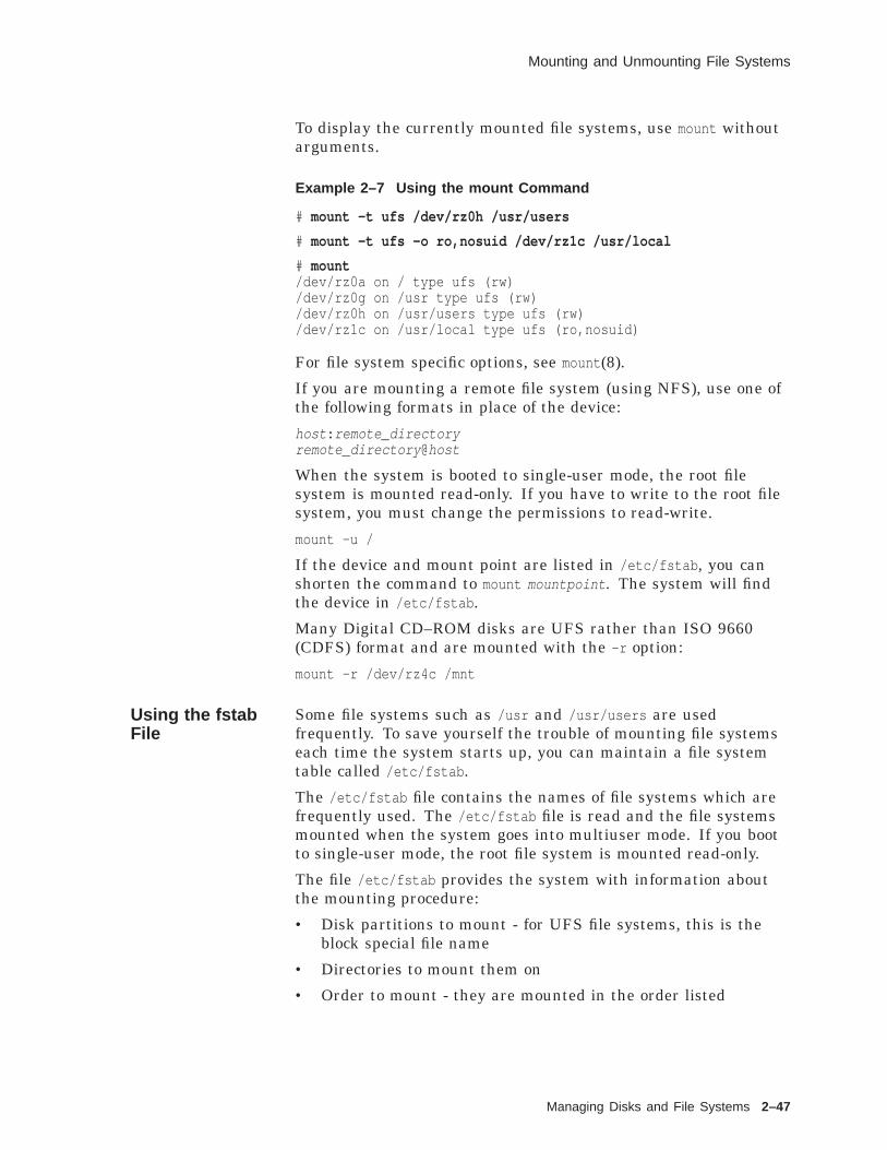
Mounting and Unmounting File Systems
To display the currently mounted file systems, use mount withoutarguments.
Example 2–7 Using the mount Command
# mount -t ufs /dev/rz0h /usr/users
# mount -t ufs -o ro,nosuid /dev/rz1c /usr/local
# mount/dev/rz0a on / type ufs (rw)/dev/rz0g on /usr type ufs (rw)/dev/rz0h on /usr/users type ufs (rw)/dev/rz1c on /usr/local type ufs (ro,nosuid)
For file system specific options, see mount (8).
If you are mounting a remote file system (using NFS), use one ofthe following formats in place of the device:
host : remote_directoryremote_directory @host
When the system is booted to single-user mode, the root filesystem is mounted read-only. If you have to write to the root filesystem, you must change the permissions to read-write.
mount -u /
If the device and mount point are listed in /etc/fstab , you canshorten the command to mount mountpoint . The system will findthe device in /etc/fstab .
Many Digital CD–ROM disks are UFS rather than ISO 9660(CDFS) format and are mounted with the -r option:
mount -r /dev/rz4c /mnt
Using the fstabFile
Some file systems such as /usr and /usr/users are usedfrequently. To save yourself the trouble of mounting file systemseach time the system starts up, you can maintain a file systemtable called /etc/fstab .
The /etc/fstab file contains the names of file systems which arefrequently used. The /etc/fstab file is read and the file systemsmounted when the system goes into multiuser mode. If you bootto single-user mode, the root file system is mounted read-only.
The file /etc/fstab provides the system with information aboutthe mounting procedure:
• Disk partitions to mount - for UFS file systems, this is theblock special file name
• Directories to mount them on
• Order to mount - they are mounted in the order listed
Managing Disks and File Systems 2–47

Mounting and Unmounting File Systems
So root directory (/) should be listed first, and any file systemshould be listed above a file system which will be mounted underit. Example 2–8 shows a sample /etc/fstab file.
Example 2–8 An /etc/fstab File
# cat /etc/fstab1 2 3 4 5 6
/dev/rz0a / ufs rw 1 1/dev/rz0g /usr ufs rw 1 2/dev/rz0b swap1 ufs sw 0 0/dev/rz0h /usr/users ufs rw 1 2/usr/share/man@tinker /usr/share/man nfs ro,bg,soft,nosuid 0 0/dev/rz1c /usr/lib/dxbook cdfs ro 0 0
1 Special device name or remote file system to be mounted
2 Directory where the file system is mounted
3 Type of file system: ufs, nfs, swap, or cdfs
4 Mount options for the type of file system (a comma-separatedlist)Common options:
ro Read-only accessrw Read-write accessrq Read-write access with quotassw Swap/paging spacexx Ignore this file system entry
5 Backup frequency for dump: 0 indicates the file system is notbacked up
6 fsck pass order (root is 1): 0 indicates the file system is notchecked
You must be superuser to edit the /etc/fstab file.
For file system specific options, see mount (8), mount (8), mount (8).
The fsck command can check file systems on different drivessimultaneously, improving its performance. However, file systemson the same drive are checked sequentially.
Caution for CDFS
Compact disks are read-only, so they should not be checkedby fsck (passnum should be 0).Do not create an entry in /etc/fstab for a compact diskunless you leave the disk in the drive. If you boot yoursystem without a compact disk in the drive indicated infstab , mount will hang trying to mount it.
2–48 Managing Disks and File Systems

Mounting and Unmounting File Systems
Using theumountCommand
Use the umount command to unmount a file system. The formatfor umount is:
umount [ options ] [ mountpoint ]
options Some options include:-A Attempts to unmount all file systems
currently mounted
-a Unmounts all file systems listed in /etc/fstab
-t Specifies a type of file system to unmount;for example
# umount -a -t ufs
-h Specifies a host for unmounting all filesystems remotely mounted in /etc/fstab .
mountpoint The existing directory where the file system ismounted
You must unmount a file system if you want to check it with fsckor change its partition size with disklabel .
You cannot unmount a file system if one of the files or directoriesis in use.
You cannot unmount the root file system. Example 2–9 showshow to use the umount command.
Example 2–9 Using the umount Command
# mount/dev/rz0a on / type ufs (rw)/dev/rz0g on /usr type ufs (rw)/dev/rz0h on /usr/users type ufs (rw)/dev/rz1c on /usr/local type ufs (ro)/usr/share/man@tinker on /usr/share/man type nfs (ro,bg,soft,nosuid)
# umount /usr/local
# umount /usrumount /dev/rz0g: Mount device busy
# umount -h tinker
The following example shows the mount and umount commands.
Example 2–10 Mounting and Unmounting File Systems
# who 1superman tty00 Apr 29 13:57# ls /mnt 2# pwd 3/
(continued on next page)
Managing Disks and File Systems 2–49

Mounting and Unmounting File Systems
Example 2–10 (Cont.) Mounting and Unmounting File Systems
# mount 4/dev/rz0a on / type ufs (rw)/dev/rz0g on /usr type ufs (rw)# mount /dev/rz2a /mnt 5# mount 6/dev/rz0a on / type ufs (rw)/dev/rz0g on /usr type ufs (rw)/dev/rz2a on /mnt type ufs (rw)# ls /mnt 7.#clipboard.clp .@today’s_test.doc [email protected] .DesktopState [email protected] .deskprint today’s_test.doc# umount /dev/rz2a 8# mount 9/dev/rz0a on / type ufs (rw)/dev/rz0g on /usr type ufs (rw)# ls /mnt 1 0
#
1 Superuser ensures that no one is logged in and using thedirectory /mnt .
2 Directory /mnt is empty.
3 Superuser ensures that working directory is not the directory/mnt .
4 Superuser wants to mount /dev/rz2a and displays the list ofcurrently mounted file systems. The file system /dev/rz2a isnot mounted.
5 Superuser mounts the file system /dev/rz2a under thedirectory /mnt .
6 The mount table shows that /dev/rz2a is now mounted under/mnt .
7 The directory /mnt was empty before the mount. Now it isan access point to the files contained in the file system on/dev/rz2a .
8 Superuser unmounts /dev/rz2a .
9 The mount table shows that /dev/rz2a is no longer mounted.
1 0 The directory /mnt is empty and is no longer an access point toa mounted file system.
2–50 Managing Disks and File Systems

Summary
Summary
Disk Drives In a disk:
• A disk surface is the top or bottom of a disk platter.
• The drive head, one per surface, is mounted on a movable armto read and write on the disk surface.
• A disk track is a circle as traced by a head on a rotatingsurface.
• A disk cylinder is an imaginary figure formed by dropping atop surface track down through the tracks directly below onall surfaces.
• A disk sector is the surface pie slice on a single track.
LogicalVolumes
Logical Volumes add a level of abstraction between the physicaldisk devices and the file system.
Partitions andFile Systems
Partitions:
• Are logical divisions of a disk drive.
• Have default sizes, by drive type, but can be altered by thesuperuser.Default partition sizes are in /etc/disktab .
• Each partition can hold one file system.
File systems:
• Are a hierarchical structure consisting of directories and files.
• Each file system is contained in a partition unless the LogicalStorage Manager is used.
• File systems must not overlap.
• Separate file systems can be mounted together to form onevisible hierarchy.
Viewing andChangingPartition Sizeswith CDE
Partition size information is stored in the disk label.
• To display the current partition sizes, use the CDE DiskManager to view current disk label settings.
• Use the CDE Disk Manager to change the disk label.
Viewing andChangingPartition Sizes
Partition size information is stored in the disk label.
• To display the current partition sizes, use disklabel -r withthe raw device name for partition a or c.
• Use disklabel -e -r to change the disk label.
Managing Disks and File Systems 2–51

Summary
Digital UNIXFile Systems
Digital UNIX supports the following file systems:
• Virtual file system (VFS) — a generic file system interfaceallowing transparent access to other file system types
• UNIX file system (UFS) — the Berkeley fast file system
• NFS (Network File System) — mount directories across thenetwork and treat them as local
• Memory File System (MFS)
• Compact disk file system (CDFS) (ISO 9660) — mountcompact disks, read-only
• POLYCENTER Advanced File System (AdvFS)
• File on File Mounting File System (FFM)
• /proc File System
SystemOrganization
The Digital UNIX operating system supports the following filetypes.
File Type Symbol Description
Regular file - Executable program, text, or sourcecode
Directory d Contains the names of files or otherdirectories
Characterdevice file
c References a device driver that doesits own input and output buffering,such as a terminal
Block device file b References a device driver thatperforms I/O in large chunks and thekernel provides buffering support,such as a disk
UNIX domainsocket
s Provides a communicationconnection between processes
Named pipe p Provides a communicationconnection between processes
Symbolic link l Contains the name of another file
System files are organized by function and use. The major systemdirectories are as follows:
2–52 Managing Disks and File Systems

Summary
Directory Description
/ The root directory of the hierarchy; includes filesand directories used to boot and initialize theoperating system
/dev Character and block device files
/etc System administration files and databases
/sbin Commands to boot and initialize the system insingle-user mode
/tmp Temporary files
/usr Local commands, reference pages, libraries,spooling directories, and so forth
/var Multipurpose log, temporary, varying, and spoolfiles
Advanced FileSystem
The POLYCENTER Advanced File System (AdvFS) is a local filesystem that offers rapid crash recovery, extended capacity, onlinemanagement, and enhanced performance.
The Advanced File System consists of two components:
• Advanced File System is a file system option with the DigitalUNIX operating system
• Advanced File System utilities is a separately licensed,optional layered product
The key concept in the AdvFS design is the separation of physicalstorage layer and directory hierarchy layer.
Two new concepts in the AdvFS design are file domain and fileset.
• A file domain is a named set of one or more volumes thatprovides a shared pool of physical storage.
• A fileset is a uniquely named set of directories and files thatform a subtree structure.
Creating a FileSystem
To create a new file system, use the newfs (8) command.
Checking a FileSystem
To check a file system, use the fsck (8) command.
Mounting a FileSystem
To make the files in a file system available to users, mount thefile system into the directory hierarchy.
• To mount a file system under an existing directory, use mount .
• File systems mounted regularly can be listed in /etc/fstab (4)and will be mounted automatically when the system boots tomultiuser mode.
• To unmount a file system, use umount .
Managing Disks and File Systems 2–53
Exercises
Exercises
Viewing andChangingPartition Sizeswith CDE
The director of finance will be implementing a new applicationwhich requires (for security purposes) its own file system with astorage requirement of 100M bytes. Create a file system on yoursystem that will support the new application.
1. Use the CDE Disk Manager to apply the changes to theappropriate disk.
2. Create a new d partition suitable for use with UFS.
Note
Do not commit the changes on disk unless directed to doso by your instructor!
Viewing andChangingPartition Sizeswith disklabel
1. Display the disk label of a disk on your system.
2. Your instructor will tell you if a disk is available to berepartitioned. If so, use disklabel -e to edit the disk label. Donot use the -r option. If your instructor does not specify whichpartitions to change, increase partition d by 1000 sectors andmake other appropriate changes.What happens when you display the disk label?
3. Do the above exercise again, this time using the -r option onedit. Add a name (label) to your disk.
Creating a FileSystem
1. Check the Reference Pages for newfs (8) options.
2. Your instructor will tell you if a disk partition is available forcreating a file system. If so, use newfs to create a UFS filesystem.
Checking a FileSystem
1. Check the Reference Pages for fsck(8) options.
2. Use fsck without options to check a file system.
3. Use fsck with the -y option to check a file system.
Mounting FileSystems
1. Check the Reference Pages for mount (8), mount (8cdfs),mount (8nfs), and mount (8ufs) options.
2. Use mount without arguments to display currently mounted filesystems.
3. Display the /etc/fstab file. What is the purpose of this file?Name two programs that use this file.
2–54 Managing Disks and File Systems

Exercises
4. Your instructor will tell you if a file system is available topractice mounting and unmounting.
a. In your home directory, create a subdirectory named test .
b. In that subdirectory, create a file named file1 .
c. Be sure you are in your home directory (not the newsubdirectory).
d. Become root user.
e. Mount the file system (get the device name from yourinstructor) under your test directory.
f. List the test directory. What happened to the file file1 ?
g. Create a new file newfile1 in the test directory.
h. Unmount the file system.
i. List the test directory. Was the file file1 deleted?
j. Create a subdirectory test2 and mount the file systemthere.
k. Where is the file newfile1 ?
Managing Disks and File Systems 2–55
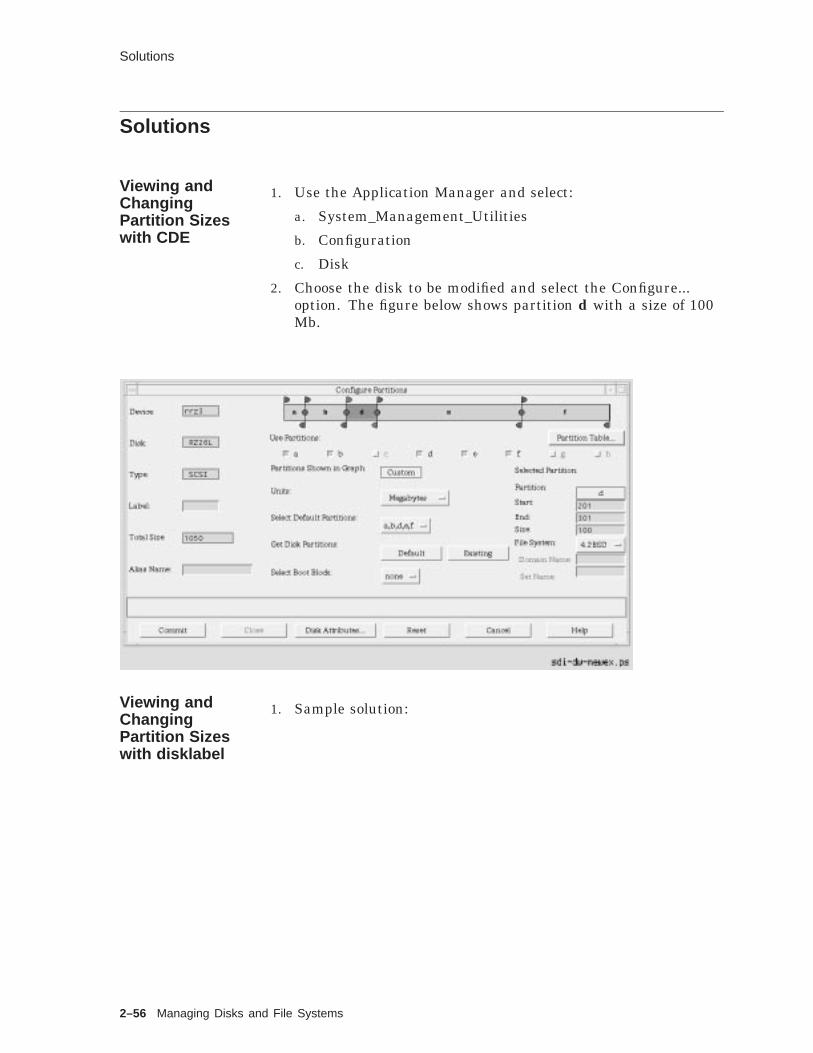
Solutions
Solutions
Viewing andChangingPartition Sizeswith CDE
1. Use the Application Manager and select:
a. System_Management_Utilities
b. Configuration
c. Disk
2. Choose the disk to be modified and select the Configure...option. The figure below shows partition d with a size of 100Mb.
Viewing andChangingPartition Sizeswith disklabel
1. Sample solution:
2–56 Managing Disks and File Systems

Solutions
# disklabel -r /dev/rrz0a# /dev/rrz0a:type: SCSIdisk: rz55label:flags:bytes/sector: 512sectors/track: 36tracks/cylinder: 15sectors/cylinder: 540cylinders: 1224rpm: 3600interleave: 1trackskew: 0cylinderskew: 0headswitch: 0 # millisecondstrack-to-track seek: 0 # millisecondsdrivedata: 0
7 partitions:# size offset fstype [fsize bsize cpg]
a: 40960 0 unused 1024 8192 # (Cyl. 0 - 75*)b: 122880 40960 unused 1024 8192 # (Cyl. 75*- 303*)c: 649040 0 unused 1024 8192 # (Cyl. 0 - 1201*)d: 152446 163840 unused 1024 8192 # (Cyl. 303*- 585*)e: 152446 316286 unused 1024 8192 # (Cyl. 585*- 868*)f: 180308 468732 unused 1024 8192 # (Cyl. 868*- 1201*)g: 485200 163840 4.2BSD 1024 8192 16 # (Cyl. 303*- 1201*)
#
2. Editing the disk label without the -r option affects only thecopy in memory, not the label on the disk.
3. Displaying the disk label should show your changes: forpartition d, increase the size by 1000 but not the offset; ifpartition e is adjacent to d, increase e’s offset by 1000 anddecrease its size by 1000. Add the disk name after the label:field.
Creating a FileSystem
1. No solution required.
2. # newfs /dev/rrz1g RZ56
Checking a FileSystem
1. No solution required.
2. # fsck /dev/rrz1g
3. # fsck -y /dev/rrz1g
Mounting FileSystems
1. No solution required.
2. Solution varies.
# mount/dev/rz0a on / type ufs (rw)/dev/rz0g on /usr type ufs (rw)/dev/rz0h on /usr/users type ufs (rw)/dev/rz1c on /usr/local type ufs (ro)
Managing Disks and File Systems 2–57
Solutions
3. The fstab file contains descriptive information about the filesystems usually mounted.fstab is used by dump, fsck , mount , and umount .
4.
a. $ mkdir testb. $ touch test/file1c. $ pwd
/usr/users/med. $ su
e. # mount /dev/rz1d /usr/users/me/testf. # ls test
lost+foundg. # touch test/newfile1h. # umount /dev/rz1di. # ls test
file1j. $ mkdir test2
# mount /dev/rz1d /usr/users/me/test2k. # ls test2
lost+found newfile1#
The file system was temporarily mounted over the contents ofthe test directory. No file was deleted.
2–58 Managing Disks and File Systems

3System Shutdown and Startup
System Shutdown and Startup 3–1

About This Chapter
About This Chapter
Introduction As system manager, you may have to add system resources ormonitor system resources in single user mode. In these cases youmust shut down and reboot your system or shut down to singleuser mode. You may even have to modify the system startupprocedures.
This chapter discusses the shutdown , halt , reboot , and initcommands to shutdown, reboot and change run levels on a DigitalUNIX system.
The chapter also discusses booting Digital UNIX systems.Appendix A shows commands, environment variables andexamples for booting a number of systems. Refer to AppendixA and to the section in the System Administration guide thatexplains booting for your hardware.
The chapter provides background information on what happenson a UNIX system as it boots. Finally, it provides informationabout, and examples of, the initialization files.
Lab exercises provide practice shutting down and booting thesystem to single user and multiuser mode, and examining theinitialization files.
Objectives To effectively control system startup and shutdown, you should beable to:
• Shut down a UNIX system to single user mode or the haltstate using the command line interface
• Shut down a UNIX system to single user mode or the haltstate using the CDE Shutdown application
• Bootstrap a powered down or halted Digital UNIX system anddescribe how the init command changes system run levels
• Describe the need for, and uses of, the Digital UNIXinitialization files
Resources For more information on the topics in this chapter, see thefollowing:
• Digital UNIX System Administration, Chapters 2, 3 and 4
• Nemeth, Snyder, & Seebass, UNIX System AdministrationHandbook, Chapter 2
• Leffler, McKusick, Karels, and Quarterman, The Designand Implementation of the 4.3BSD UNIX Operating System,Chapter 13
• Digital Services Advisory for Digital UNIX, Chapter 12Note that this is Digital Confidential
3–2 System Shutdown and Startup

Shutting Down and Rebooting the System
Shutting Down and Rebooting the System
Overview Shutting down, or rebooting the system is not usually a scheduledevent, but it is something you, as system administrator, willperform periodically. Most of the time you will shut down thesystem in a manner to cause the least disruption to the users.However, you will occasionally have to shut down the systemrapidly, causing some disruption for the users. There will alsobe cases when the system shuts itself down suddenly, causingsubstantial disruption to the users.
This section describes various methods for shutting down andrebooting the system.
Reasonsfor SystemShutdown andReboot
When adding new hardware, the system must be powered downprior to adding the new hardware. The system must first be shutdown. After the system has been shut down and the hardwareinstalled, you must modify the kernel configuration file andrebuild the kernel.
To install a new version of system software, you must shut thesystem down and boot from the distribution media. To upgradesystem software, you may have to shut down.
To install a layered product, you may need to shut the systemdown to single user mode, install the software, make somechanges to the configuration file, then build a new kernel andreboot the system. Note that not all layered products requirechanges to the configuration file and building a new kernel.
If you modify the system by altering option values in theconfiguration file to enhance system performance, a new kernelmust be built, then the system rebooted.
File systems can become corrupted by improper shutdownprocedures, hardware failures, or by power outages and surges.If file system corruption is suspected, you will want to shut downand reboot to run a file system consistency check, fsck . If fsckdetects an unexpected inconsistency, it leaves the system in singleuser mode, allowing you to run the program manually.
After noticing several errors of the same type in the event log,you may suspect an impending hardware failure. You may wantto shut down the system to more closely examine the suspecthardware.
System Shutdown and Startup 3–3

Shutting Down and Rebooting the System
Methodsfor SystemShutdown
There are a number of ways you can shut down and reboot yourUNIX system.
• Use the:
CDE Shutdown manager
shutdown command
halt or fasthalt command
init command
• Send a signal to the init process.
• Turn off the power.
Figure 3–1 provides an overview of various commands used toshut down or reboot a UNIX system.
Figure 3–1 Overview of System Shutdown and Reboot
#
>>>
>>>halt, fasthalt
ZKOX−055000111−09−RGS
reboot
shutdown −r, reboot
shutdown −h, init 0
shutdown, init s
HaltMode
SingleUserMode
MultiuserMode
Using theshutdownCommand
Use the shutdown command to halt, reboot, or return to single usermode. The command provides the most consideration for otherusers. You must be logged in as root to execute this command.
The format for the shutdown command is:
shutdown [-fhknr] time [ warning-message ]
The shutdown options are shown in Table 3–1.
3–4 System Shutdown and Startup

Shutting Down and Rebooting the System
Table 3–1 shutdown Command Options
Option Causes
A shutdown to single user mode.
-f A fast shutdown, bypassing the messages to other usersand bringing the system down as quickly as possible.
-h The system is to shut down and halt at console level.
-k A shutdown message to be sent to all users, warningthem of an impending shutdown. The system does notactually shut down.
-n A shutdown without synchronizing the disks or loggingthe shutdown.
-r The system is to shut down and automatically reboot.
The time argument specifies when shutdown will bring the systemdown. You can use now for an immediate shutdown or specify afuture time with one of two formats:
Format Description
+number Brings the system down in number minutes.
yymmddhhmm Shuts the system down at the absolute timespecified. The hours and minutes may be separatedby a colon (:).
The other argument is the message you want send to all userscurrently logged in to the system. This optional message is sentalong with the shutdown notification message at increasinglyshorter intervals as the time for shutdown approaches.
Shutting Downto Single UserMode
When used without any options, the shutdown command brings thesystem to single user mode. The system notifies all users of theimpending shutdown.
An example shutdown command might look like the following:
shutdown +10 System coming down for routine maintenance
Besides notifying the users of the impending shutdown, thesystem also:
• Disables logins
• Logs the shutdown in the event log file and /var/adm/wtmp
• Stops accounting and event logging
• Stops all remaining processes
• Sends the TERM signal to the init process, which brings thesystem to single user mode
System Shutdown and Startup 3–5

Shutting Down and Rebooting the System
Shutdown is complete when the system console displays singleuser mode.
INIT: SINGLE USER MODE#
You have superuser access to the system through the console,using the Bourne shell to perform administrative tasks.
Prior to the transition from multiuser to single user mode, theoutput from the process status (ps -aef ) command might look likethe one shown in Example 3–1.
Example 3–1 Typical Multiuser Mode ps Output
UID PID PPID C STIME TTY TIME CMDroot 0 0 1.5 Aug 19 ?? 04:51:51 [kernel idle]root 1 0 0.0 Aug 19 ?? 0:00.39 /sbin/init -saroot 3 1 0.0 Aug 19 ?? 0:00.42 /sbin/kloadsrvroot 40 1 0.0 Aug 19 ?? 1:54.21 /sbin/updateroot 113 1 0.0 Aug 19 ?? 0:01.15 /usr/sbin/syslogdroot 115 1 0.0 Aug 19 ?? 0:00.01 /usr/sbin/binlogdroot 177 1 0.0 Aug 19 ?? 0:53.15 /usr/sbin/routed -qroot 309 1 0.0 Aug 19 ?? 0:00.55 /usr/sbin/portmaproot 311 1 0.0 Aug 19 ?? 0:00.11 /usr/sbin/mountd -iroot 313 1 0.0 Aug 19 ?? 0:00.02 /usr/sbin/nfsd -t8 -u8root 315 1 0.0 Aug 19 ?? 0:00.01 /usr/sbin/nfsiod 7root 318 1 0.0 Aug 19 ?? 0:00.02 /usr/sbin/rpc.statdroot 320 1 0.0 Aug 19 ?? 0:00.05 /usr/sbin/rpc.lockdroot 346 1 0.0 Aug 19 ?? 0:00.03 /usr/sbin/dnalimdroot 349 346 0.0 Aug 19 ?? 0:05.28 /usr/sbin/dnaevldroot 381 346 0.0 Aug 19 ?? 3:01.33 /usr/sbin/dnascdroot 382 381 0.0 Aug 19 ?? 0:00.10 /usr/sbin/dnansdroot 383 381 0.0 Aug 19 ?? 0:00.37 /usr/sbin/dnaksdroot 387 346 0.0 Aug 19 ?? 0:10.55 /usr/sbin/dnsadvroot 429 1 0.0 Aug 19 ?? 0:03.10 /usr/sbin/dtssdroot 433 387 0.0 Aug 19 ?? 0:00.21 /usr/sbin/dnsclerk -U rroot 435 346 0.0 Aug 19 ?? 0:00.07 /usr/sbin/dnanodedroot 482 1 0.0 Aug 19 ?? 0:00.37 /usr/sbin/osaknmdroot 522 1 0.0 Aug 19 ?? 0:14.64 -accepting connectionsroot 542 1 0.0 Aug 19 ?? 0:03.79 /usr/sbin/xntpd -g -x -root 576 1 0.0 Aug 19 ?? 0:04.26 /usr/sbin/os_mibsroot 579 1 0.0 Aug 19 ?? 1:37.92 /usr/sbin/snmpdroot 581 1 0.0 Aug 19 ?? 28:48.23 /usr/sbin/advfsdroot 592 1 0.0 Aug 19 ?? 0:00.17 /usr/sbin/inetdroot 625 1 0.0 Aug 19 ?? 0:00.60 /usr/sbin/cronroot 657 1 0.0 Aug 19 ?? 0:00.20 /usr/lbin/lpdroot 676 1 0.0 Aug 19 ?? 0:00.12 /usr/bin/mmeserver -conroot 690 1 0.0 Aug 19 ?? 0:00.49 /usr/dt/bin/dtlogin -daroot 702 1 0.0 Aug 19 ?? 0:00.84 lpsbootd -F /etc/lpsodbroot 705 1 0.0 Aug 19 ?? 0:00.02 /usr/sbin/getty /dev/laroot 706 1 0.0 Aug 19 ?? 0:00.02 /usr/sbin/getty /dev/laroot 707 1 0.0 Aug 19 ?? 0:00.02 /usr/sbin/getty /dev/laroot 708 1 0.0 Aug 19 ?? 0:00.02 /usr/sbin/getty /dev/laroot 709 1 0.0 Aug 19 ?? 0:00.02 /usr/sbin/getty /dev/laroot 710 1 0.0 Aug 19 ?? 0:00.02 /usr/sbin/getty /dev/laroot 711 1 0.0 Aug 19 ?? 0:00.02 /usr/sbin/getty /dev/laroot 712 690 0.0 Aug 19 ?? 38:37.93 /usr/bin/X11/X :0 -authroot 781 592 0.0 Aug 19 ?? 0:00.10 rpc.ttdbserverd
3–6 System Shutdown and Startup

Shutting Down and Rebooting the System
The ps -aef command output after transition to single user modemight look like the one shown in Example 3–2. Notice how fewprocesses are running.
Example 3–2 Typical Single User ps Output
UID PID PPID C STIME TTY TIME CMDroot 0 0 1.5 Aug 19 ?? 04:51:51 [kernel idle]root 1 0 0.0 Aug 19 ?? 0:00.39 /sbin/init -saroot 4921 4744 0.0 Aug 26 ttyp1 0:01.27 kshroot 20911 20901 0.0 15:47:22 ttypb 0:00.06 ps -aef
CompleteShutdown
When used with the -h or -r options, the shutdown commandtypically performs the following functions in addition to thefunctions performed by the shutdown command when used with nooptions:
• Runs the sync command to synchronize the disks
• Unmounts the file systems
• Halts the processor
If the command was shutdown -r , the shutdown commandautomatically starts a reboot operation to return the system tomultiuser mode.
Using the haltCommandto Stop theProcessor
Use the halt command to cause a transition from single usermode to the halt state. Use it only if you are not going to restartimmediately. You can turn off the system power when the systemdisplays the console prompt.
The halt command:
• Logs the system halt in the event log and /var/adm/wtmp
• Kills running processes
• Synchronizes the disks
• Halts the processors
• Can be run only by root
Descriptions for the various options to the halt command areshown in Table 3–2.
Table 3–2 halt Command Options
Option Function
-l Does not log the halt
-n Prevents the use of sync to write data to the disks anddoes not log the halt
-q Causes a quick halt; does not log the halt and makesno attempt to kill the system processes
System Shutdown and Startup 3–7

Shutting Down and Rebooting the System
For example:
# haltsyncing disks... donehalting.... (transferring to monitor)
The halt is logged in /usr/adm/syslog.dated/ date /auth.log .
Using thefasthaltCommand
The fasthalt command halts the system and flags a subsequentreboot not to carry out a file system consistency check (fsck ).
The fasthalt command:
• Creates the file /fastboot , used by startup scripts to preventthe execution of fsck
• Invokes the halt command to halt the processors
Note
Use the fasthalt command with extreme caution andnever use it unless you are certain that the file systemsare in excellent shape.
The format for the fasthalt command is:
fasthalt [-l -n -q]
The options for the fasthalt command are described inTable 3–3.
Table 3–3 fasthalt Command Options
Option Function
-l Does not log the halt
-n Prevents the use of sync to write data to the disks anddoes not log the halt
-q Causes a quick halt; does not log the halt and makesno attempt to kill the system processes
Shutting Downto Single UserMode with init
Use the init command to shut down the system from multiusermode to single user mode.
The format for the command is:
init s
The init command scans the /etc/inittab file to determine whichcommands and scripts must be run to bring the system to singleuser mode.
3–8 System Shutdown and Startup

Shutting Down and Rebooting the System
Stopping theProcessor withinit
A Digital UNIX system may be halted with the init command.The format for the command is:
init 0
The init command scans the /etc/inittab file to determine whichcommands and scripts must be run to bring the system to haltmode.
The init command may be executed in either multiuser orsingle user mode. You would not normally use init to shut downthe system or halt the system unless you have provided amplewarning to the users with the wall command.
Other Methodsof ShuttingDown theSystem
Other methods for shutting down the system include:
• Sending the TERM signal (15) to the init process brings thesystem to single user mode.
• Sending the KILL signal (9) to the init process may bring thesystem to console level.
• Turning off the power.
Note
These methods are not recommended for shutting downa system because the results are unpredictable. Thebest way to shut down the system is with the shutdowncommand.
Rebooting theSystem
If you make changes to system software or configuration files thatare executed only when the system is booted, you must reboot forthese changes to take effect. Also some devices, such as printers,can become unusable for unknown reasons and require resetting,which may not be possible without reinitializing the system.Under these circumstances, you may have to reboot the system.
Using therebootCommand
The reboot command normally stops all processes, synchronizesthe disks, logs the reboot, and writes a shutdown entry into thelogin accounting file.
The reboot command does not provide a time delay, nor does itinform users of an impending shutdown and reboot. Do not usethe reboot command if users are logged in; use the shutdown -rcommand instead.
You must have root privileges to use the reboot command.
The format for the reboot command is:
reboot [-lnq]
The descriptions of the various reboot options are shown inTable 3–4.
System Shutdown and Startup 3–9
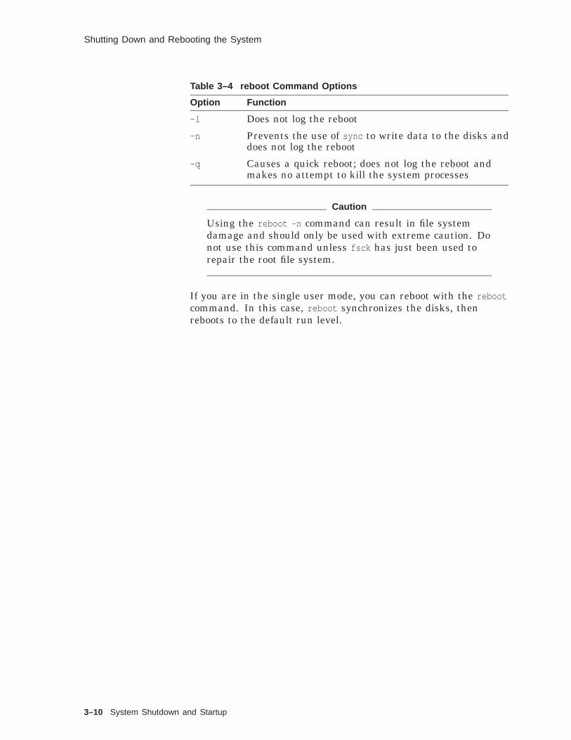
Shutting Down and Rebooting the System
Table 3–4 reboot Command Options
Option Function
-l Does not log the reboot
-n Prevents the use of sync to write data to the disks anddoes not log the reboot
-q Causes a quick reboot; does not log the reboot andmakes no attempt to kill the system processes
Caution
Using the reboot -n command can result in file systemdamage and should only be used with extreme caution. Donot use this command unless fsck has just been used torepair the root file system.
If you are in the single user mode, you can reboot with the rebootcommand. In this case, reboot synchronizes the disks, thenreboots to the default run level.
3–10 System Shutdown and Startup

Shutting Down and Rebooting the System with CDE
Shutting Down and Rebooting the System with CDE
Overview Using the CDE Shutdown application applies the same underlyingmechanics of the system shutdown as the command line interfacecommand shutdown . The Common Desktop Environment merelymakes the task easier to perform through the use of thewindow-like interface.
InvokingShutdown
This application is invoked in the standard manner, beginningwith the selection of the Application Manager icon in the FrontPanel.
• Application Manager
• System_Admin
• DailyAdmin
• Shutdown
The following figure shows the Application Manager - DailyAdminwindow, and the Get Password Pop-up window.
Figure 3–2 Shutdown Selection
System Shutdown and Startup 3–11

Shutting Down and Rebooting the System with CDE
Note that the shutdown application will prompt the user forthe proper root password. No further activity is permitted untilthe password is supplied. After the correct password is entered,the Shutdown Manager window is displayed, as shown in thefollowing figure.
Figure 3–3 Shutdown Window
ShutdownOptions
The selections include:
• Halt
• Reboot
• Single User
• Message Only
Each option gives the administrator the same functionality as thecommand line interface command shutdown .
Click the arrows in the time scroll bar to change the time toshutdown.
You can display more options by clicking MB1 on the darkdownward arrow. The three additional controls are:
• Broadcast Message to NFS Clients - used where users onanother host may be accessing file remotely from this host
• Preshutdown Script - may be defined to shut down with aparticular methodology
3–12 System Shutdown and Startup
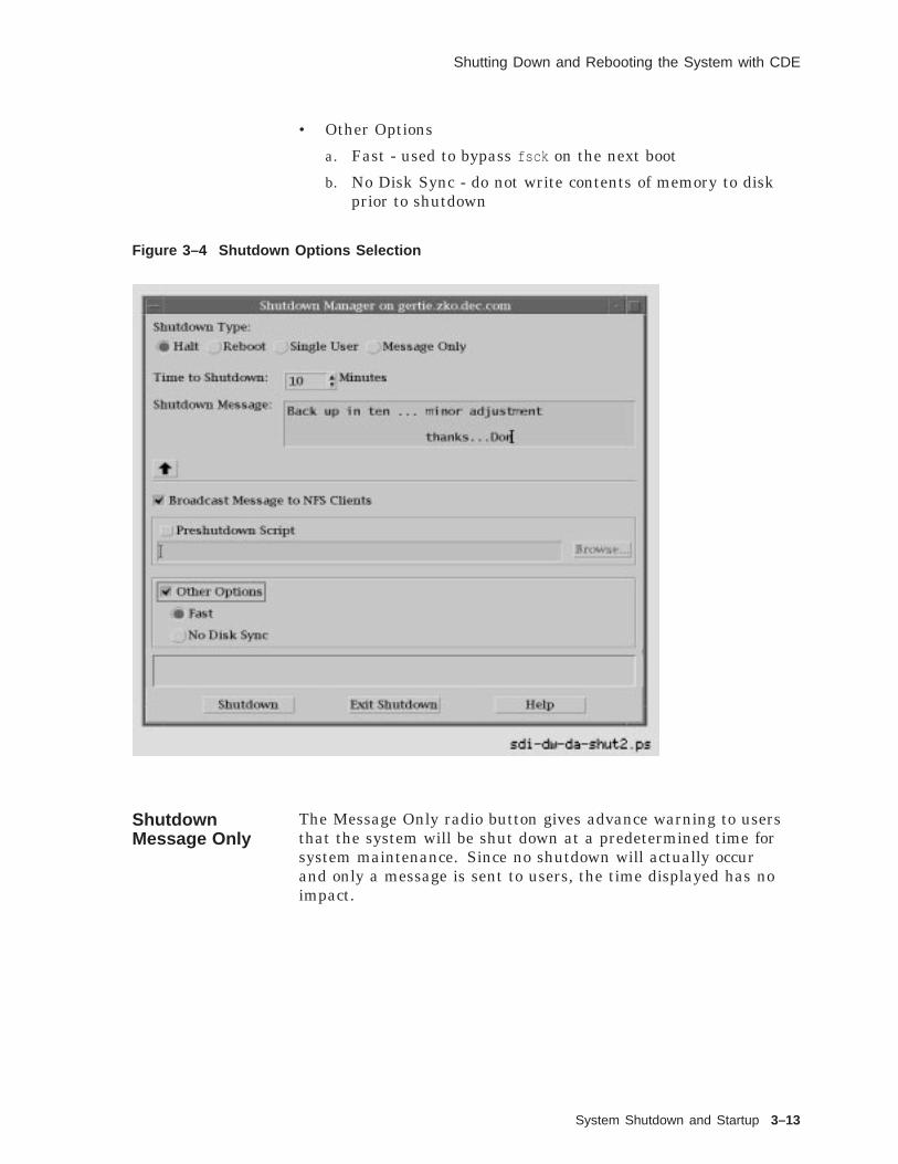
Shutting Down and Rebooting the System with CDE
• Other Options
a. Fast - used to bypass fsck on the next boot
b. No Disk Sync - do not write contents of memory to diskprior to shutdown
Figure 3–4 Shutdown Options Selection
ShutdownMessage Only
The Message Only radio button gives advance warning to usersthat the system will be shut down at a predetermined time forsystem maintenance. Since no shutdown will actually occurand only a message is sent to users, the time displayed has noimpact.
System Shutdown and Startup 3–13

Shutting Down and Rebooting the System with CDE
Figure 3–5 Warning Users of Shutdown
3–14 System Shutdown and Startup

Shutting Down and Rebooting the System with CDE
ShutdownReboot
Selecting this shutdown option will cause a shutdown based onthe time selected, followed by an automatic reboot.
Figure 3–6 Shutdown Reboot
System Shutdown and Startup 3–15

Bootstrapping a Digital UNIX System
Bootstrapping a Digital UNIX System
Overview Bootstrapping, more commonly called booting, is the process ofstarting up a computer from a powered-down or halted condition.During the boot process, the operating system kernel is loadedinto memory and started. Many tasks must be performed duringthis process to initialize the system before it can be used.
Several problems can prevent a system from booting including:
• Corrupt kernel file
• Configuration does not match kernel configuration
• Hardware problems
• Damaged file systems
• Corrupt initialization files
The booting process:
• Is hardware dependent
• Differs from system type to system type
Steps in theBootstrapProcess
The bootstrapping process can be divided into seven steps:
1. Load the kernel of the operating system into memory.
2. Initialize the kernel.
3. Check hardware configuration.
4. Create system processes.
5. Superuser intervention for manual boot.
6. Execute the initialization script files.
7. Multiuser operation.
Loading theKernel
The kernel of the operating system is a program, and the firststep in the bootstrap process is to load this program into memoryso that it can be executed. The default kernel path for DigitalUNIX is /vmunix .
Loading the operating system is generally a multistage process:
1. The console software reads and loads the contents of logicalblock number (LBN) 0 (bootblock).
2. The code from block 0 has a few bytes of code which reads theprimary bootstrap code from LBN 1-15.
3. This code then loads the secondary bootstrap program/osfboot .
3–16 System Shutdown and Startup

Bootstrapping a Digital UNIX System
4. The secondary bootstrap program is a more intelligent loaderprogram. It takes information about the boot mode, theboot device type, how to boot, and what to boot, and loadsthe specified kernel. The boot loader is generally capable ofcommunicating with the operator by issuing general and errormessages, and accepting input.
Initializing theKernel
Without sufficient memory, system initialization will fail. Ifmemory initialization succeeds, most systems display a messageindicating the amount of total memory, and the amount ofmemory available (total memory minus the memory allocated tothe kernel).
Once the kernel has been loaded, it starts executing andinitializing itself. During kernel initialization, the kernel:
• Determines how much memory is left after loading the kernel
• Reserves memory for the buffer cache and for internal statictables
• Sets up page tables and enables memory management
• Creates the environment for process 0 and several systemserver threads
• Initializes the buffer cache
HardwareConfiguration
During startup, the Digital UNIX operating system initializeshardware that has been configured into the kernel. Duringhardware initialization, problems may be caused by hardwaredevices that do not interrupt, or the presence of unsupportedhardware devices or controllers.
Digital UNIX V4.0 automatically configures devices with dynamicdevice recognition (DDR). The hardware configuration is generallydisplayed on the console.
If a device is missing or does not respond, it is marked asnonexistent, and the driver is disabled. If the device is laterreconnected, it will not be usable until the system is rebooted.
CreatingSystemProcesses
Process 0 is the kernel idle task, but is in fact multithreaded. Itconsists of many threads to perform such things as paging in andout, scheduling, swapping in and out, device interrupt service,and kernel idle.
The init Process 1 is the first process to execute a program inuser mode, and is the parent process to all subsequent processes.
The init process (/sbin/init ) is started with the -a flag, whichcauses it to run as a daemon, and differentiates it from the initcommand that root can execute.
System Shutdown and Startup 3–17

Bootstrapping a Digital UNIX System
The init command provides a means to shut down a DigitalUNIX system from multiuser mode to single user mode or to haltthe system.
Single UserMode
If the system is booted to single user mode, only the root filesystem is mounted. If a program not in the root partition isrequired, you must mount the required file system.
In addition, the root file system is mounted for read-only access.If you need to write to the root file system, you must change theaccess using the mount -u command.
Because the daemons are not running at this time, manycommands that depend upon server processes will not functionproperly (like mailx ).
Normally you would boot to single user mode to performadministrative tasks that are best accomplished with no otherusers on the system. For instance, you might be checking out newhardware, mounting and monitoring file systems, or changingdisk partitions.
When you exit single user mode with Ctrl/D or exit , init continueswith the startup tasks to transition to multiuser mode.
InitializationScriptExecution
The init process executes the rc (run command) script files.The names of these files vary among the various UNIXimplementations. In Digital UNIX and System V, the init processdetermines which script files should be run based upon entries inthe /etc/inittab file. init spawns a copy of the Bourne shell torun the script files.
Some of the tasks performed by the rc* scripts are:
• Setting the name of the system
• Checking the disks with fsck
• Mounting the file systems listed in /etc/fstab
• Removing files from the /tmp directory
• Notifying the kernel of additional swap partitions
• Starting up daemons and network services
• Turning on system accounting and disk quotas
• Configuring network interfaces
• Enabling logins
3–18 System Shutdown and Startup

Bootstrapping a Digital UNIX System
Multiuser Mode Depending upon the system, a /usr/sbin/getty process may bestarted for the console, or for a workstation, a CDE process isstarted.
Remote logins are not accepted unless the network has beenstarted.
If a getty process terminates, the init process restarts it.
Run Levels A Digital UNIX system is considered to be in a run level at anygiven time. Each run level has a specific group of processes thatrun at that level.
Digital UNIX run levels include:
0 Shut down and halt the system
s Single user mode
2 Multiuser mode with no network
3 Multiuser mode with network services
During a system boot, the init program scans each line in the/etc/init file and carries out the command on all lines containingthe number of the run level that the system is changing to.
On a Digital UNIX system, the root user can use the initcommand to change run levels. For instance, for a Digital UNIXsystem at run level three, the command init 2 would cause achange in run levels to run level two. The command, init s wouldcause a change in run levels to "s", the single user mode. Thecommand, init 0 would halt the system.
During a change in run levels, init scans the /etc/inittab file todetermine which commands and scripts to execute.
Use the who -r command to show the current run level.
System Shutdown and Startup 3–19

Digital UNIX Initialization Files
Digital UNIX Initialization Files
Overview When the Digital UNIX system boots, the kernel starts the initprocess (/sbin/init -a ), which examines the /etc/inittab file todetermine the default run level. The init process executes thecommands on any line in the /etc/inittab file with a run levelentry that corresponds to the default run level.
The superuser may execute the init command to cause a changein run levels. In this case, the desired run level is provided as anargument to the init command (for example, init 2 ). In this case,the init command signals the init process, process 1, which scansthe /etc/inittab and executes entries which contain the specifiednew run level. Entries containing the boot or bootwait action fieldare not executed.
Of course, if the system is going to be shut down, or the run levelchanged to a run level that would exclude the normal user fromsystem use, the root user should use the wall command to notifythe users the system is going to be shut down.
InitializationFiles
The following files and directories are used to boot or change runlevels for Digital UNIX:
• /etc/inittab : The first file looked at by init . It designates thescripts or programs to run for a change in run level.
• /sbin/rc0 , /sbin/rc2 , or /sbin/rc3 : Master script files used tocontrol the change to run level 0, S, 2, or 3.
• /sbin/rc0.d , /sbin/rc2.d , or /sbin/rc3.d : Directoriescontaining links to the scripts or programs to be run tochange to run level 0, S, 2, or 3. The script /sbin/rc0 usesthe directory /sbin/rc0.d , while /sbin/rc2 uses the directory/sbin/rc2.d , and /sbin/rc3 uses the directory /sbin/rc3.d .
• /sbin/init.d : The directory containing all of the scripts orprograms that can be executed during any change in run level.
Figure 3–7 provides an overview of the use of the initializationfiles for Digital UNIX.
3–20 System Shutdown and Startup

Digital UNIX Initialization Files
Figure 3–7 Overview of Digital UNIX Initialization Files
inet
s2:23:wait:/sbin/rc2 \< /dev/console \> /dev/console 2>&1
/etc/inittab /sbin/rc2.d /sbin/init.d
enlogin
ZKOX−055000111−17−RGS
K05inet../init.d/inet
/sbin
rc2
is:3:initdefault:
S25enlogin../init.d/enlogin
... ... ...
rc0
rc3
For a boot, the init process searches the /etc/inittab file for theline containing the action entry of initdefault .
For other changes in run levels, init searches for any entries,starting at the top of the file, which contain the desired new runlevel.
Changing RunLevels
Assume that you are booting run level is 2, or that we arechanging run level from 3 to 2. From the figure, the command"/sbin/rc2 < /dev/console > /dev/console 2>&1 " will be executed.Note that there are other commands in the /etc/inittab file thatare not shown that would be executed prior to this command.Standard input, standard output, and standard error are alldirected to/from the console. Those entries with the boot orbootwait action fields are executed first, than the remainingentries for the pertinent run level are executed.
The Bourne shell script file, rc2 in /sbin (/sbin/rc2 ) is executed.This script file checks to see if it is a boot (previous run levelwas single user) or if it is a change in run level. In eithercase, the link files in /sbin/rc2.d will cause execution of files in/sbin/init.d .
If we are booting, all files linked to files with an "S" as the firstletter in the file name are executed. The "S" indicates "start". Ifit is a change from run level 3 to run level 2, all files linked tofiles with a "K" as the first letter in the file name will be executed.The "K" indicates "kill". Then, all files linked to files with an"S" as the first letter in the file name are executed. If there is achange from run level 3 to run level 2, there are daemons thathave to be stopped (no network services in run level 2).
Also, if we are changing from run level 3 to run level 2, once thefiles with names beginning with "K" have been run, all /sbin/rc2.d files with names beginning with "S" are then executed. Itis the responsibility of the individual scripts to decide what to dowhen the system is coming up and going down.
In the figure, the link, K05inet --> ../init.d/inet , causes theexecution of /sbin/init.d/inet , which is just one of the commandsused to stop the network processes.
System Shutdown and Startup 3–21

Digital UNIX Initialization Files
The link, S25enlogin --> ../init.d/enlogin , causes the executionof /sbin/init.d/enlogin , which will enable logins if we arebooting.
The /etc/inittabFile
The format for the entries in the etc/inittab file is:
ID : run-levels : action : process
ID A 14-character string used to identify the entry.
run-levels Contains the number of one or more run levels.
action Indicates how to handle the process field.
process Script file or command to execute.
Definitions for the action field are shown in Table 3–5.
Table 3–5 The /etc/inittab File Action Field
Action Description
boot 1 Run when the system transfers to the specified run level from a lower levelfor the first time (that is, during booting). init starts the process but doesnot wait for its termination.
bootwait 1 Run when /etc/inittab is read for the first time. init starts the processand waits for its termination. If the process terminates, it is not restarted.
initdefault Specifies the default run level. If more than one number is present in therun level field, the highest run level is used.
off If the process is currently running, init sends SIGTERM, waits 20seconds, then sends the kill signal, SIGKILL. If the process does notexist, init ignores the entry.
once init starts the process but does not wait for its termination. When theprocess stops, it is not restarted.
powerfail If init receives the SIGPWR powerfail signal, the process is executed.
powerwait If init receives the SIGPWR powerfail signal, it executes the process andwaits for the process to terminate before resuming processing of the /etc/inittab file.
respawn If the process does not exist or if the process terminates, init restarts theprocess.
sysinit Executed before init tries to access the console.
wait init starts the process and waits for it to terminate. init will not processany further /etc/inittab entries until the process terminates.
1During booting, init processes the entries with action fields of boot or bootwait for the defined run level before processingother entries for the run level.
The fields in each entry of the /etc/inittab file are separated bycolons (:).
The ID field in the entry may be null.
If the run-level field is null, the entry is valid for all run levels.
3–22 System Shutdown and Startup

Digital UNIX Initialization Files
If the field is null, the colon must still be present.
Digital UNIX/etc/inittab File
A sample Digital UNIX /etc/inittab file is shown inExample 3–3.
Example 3–3 Digital UNIX /etc/inittab File
# cat /etc/inittabis:3:initdefault:ss:Ss:wait:/sbin/rc0 shutdown < /dev/console > /dev/console 2>&1s0:0:wait:/sbin/rc0 off < /dev/console > /dev/console 2>&1fs:23:wait:/sbin/bcheckrc < /dev/console > /dev/console 2>&1kls:Ss:sysinit:/sbin/kloadsrv < /dev/console > /dev/console 2>&1sysconfig:23:wait:/sbin/init.d/autosysconfig start < /dev/console > /dev/console 2>&1update:23:wait:/sbin/update > /dev/console 2>&1it:23:wait:/sbin/it < /dev/console > /dev/console 2>&1kmk:3:wait:/sbin/kmknod > /dev/console 2>&1s2:23:wait:/sbin/rc2 < /dev/console > /dev/console 2>&1s3:3:wait:/sbin/rc3 < /dev/console > /dev/console 2>&1cons:1234:respawn:/usr/sbin/getty console console vt100#
The following table describes some of the processes started in theinittab file.
Process Function
bcheckrc Checks and mounts file systems listed in /etc/fstab
kloadsrv Starts the kernel load server daemon for dynamicallyloading object modules
update Starts the update daemon to synchronize disks
it Makes sure the system is configured
kmknod Creates device special files for kernel layeredproducts
Entries in the/etc/inittab File
is:3:initdefault — If we are not booting to single user mode, theinit process uses this entry to determine the default run level; inthis case, 3. All entries that have a 3 in the run level field will beexecuted.
ss:Ss:wait:/sbin/rc0 shutdown — Execute the /sbin/rc0 script filewith "shutdown" as the input argument. The init process waitsuntil the rc0 script completes execution before executing anyother commands (there are no other commands with a run level of"S" or "s", in /etc/inittab )
s0:0:wait:/sbin/rc0 off — Execute the /sbin/rc0 script file with"off" as the input argument. Note that this is the same as theprevious entry, except that in this case the rc0 script has "off" asan input argument instead of "shutdown".
System Shutdown and Startup 3–23
Digital UNIX Initialization Files
fs:23:bootwait:/sbin/bcheckrc — When booting to run level 2 or3, the file systems are checked (fsck ) and mounted. Note that/sbin/bcheckrc first checks for the existence of the file /fastboot .If /fastboot exists, the file system check is bypassed. init waitsfor the script to terminate, but does not restart it.
s2:23:wait:/sbin/rc2 — When booting to run level 2 or 3, initstarts /sbin/rc2 , waits for /sbin/rc2 to terminate, and does notcontinue until the script has completed.
s3:3:wait:/sbin/rc3 — When booting to run level 3, init starts/sbin/rc3 after /sbin/rc2 completes. Again, init waits for/sbin/rc3 to terminate before it continues.
Execution of/sbin/rc*.d Files
When shutting the system down to single user mode or haltingthe system with the init command, the /sbin/rc0 script file isinvoked. When booting to run level 2 or 3, /sbin/rc2 is invoked.When booting to run level 3, /sbin/rc3 is executed after /sbin/rc2has completed. Also, if the init command is used to change therun level from 3 to 2, /sbin/rc2 is executed.
When one of the rc0 , rc2 , or rc3 scripts executes, files in thecorresponding /sbin/rc*.d directory are executed. These files arelinks to files in the /sbin/init.d directory.
A sample /sbin/rc2 is shown in Example 3–4. This script is usedwhen the system is booting to run level 2 or 3, or changing fromrun level 3 to run level 2.
3–24 System Shutdown and Startup
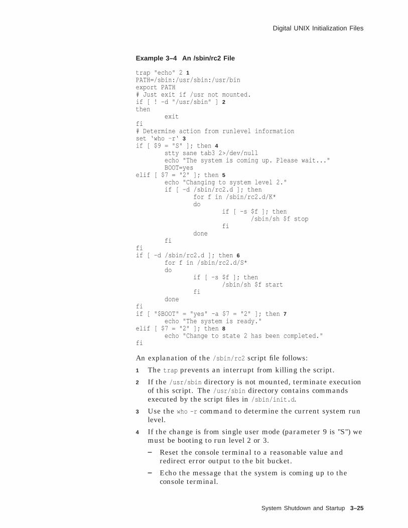
Digital UNIX Initialization Files
Example 3–4 An /sbin/rc2 File
trap "echo" 2 1PATH=/sbin:/usr/sbin:/usr/binexport PATH# Just exit if /usr not mounted.if [ ! -d "/usr/sbin" ] 2then
exitfi# Determine action from runlevel informationset ‘who -r‘ 3if [ $9 = "S" ]; then 4
stty sane tab3 2>/dev/nullecho "The system is coming up. Please wait..."BOOT=yes
elif [ $7 = "2" ]; then 5echo "Changing to system level 2."if [ -d /sbin/rc2.d ]; then
for f in /sbin/rc2.d/K*do
if [ -s $f ]; then/sbin/sh $f stop
fidone
fifiif [ -d /sbin/rc2.d ]; then 6
for f in /sbin/rc2.d/S*do
if [ -s $f ]; then/sbin/sh $f start
fidone
fiif [ "$BOOT" = "yes" -a $7 = "2" ]; then 7
echo "The system is ready."elif [ $7 = "2" ]; then 8
echo "Change to state 2 has been completed."fi
An explanation of the /sbin/rc2 script file follows:
1 The trap prevents an interrupt from killing the script.
2 If the /usr/sbin directory is not mounted, terminate executionof this script. The /usr/sbin directory contains commandsexecuted by the script files in /sbin/init.d .
3 Use the who -r command to determine the current system runlevel.
4 If the change is from single user mode (parameter 9 is "S") wemust be booting to run level 2 or 3.
Reset the console terminal to a reasonable value andredirect error output to the bit bucket.
Echo the message that the system is coming up to theconsole terminal.
System Shutdown and Startup 3–25

Digital UNIX Initialization Files
Set the BOOT variable to "yes".
5 If the present run level (the run level we are changing from) isnot single user mode, and we are changing to run level 2, thenwe must be in run level 3 (for present Digital UNIX systems).
If the directory /sbin/rc2.d exists, fork a Bourne shell toexecute every file in /sbin/rc2.d that begins with a K (kill).Pass "stop" as the argument. Keep in mind that the filesin /sbin/rc2.d are just soft links to files in /sbin/init.d .
6 If we are changing from run level 3 to run level 2, or if we arebooting to run level 2 or 3:
If the directory /sbin/rc2.d exists, fork a Bourne shellto execute every file in /sbin/rec2.d that begins withan "S" (start). Pass "start" as an argument. The files in/sbin/rc2.d are soft links to files in /sbin/init.d .
7 If the BOOT variable is "yes" (we were booting) and parameter7 from the who -r command is 2 (we are booting to run level 2),echo the message that the system is ready. If we are bootingto run level 3, we still have to execute the files in /sbin/rc3.d .When they are complete, echo the "system ready" message.
8 If we were not booting, but just changed run level from 3 to 2,echo the message "Change to state 2 has been completed".
SelectedContentsof the rc*.dDirectories
Portions of ls -o outputs are shown for the /sbin/rc*.d directoriesin Example 3–5.
Example 3–5 Selected Contents of the rc*.d Directories
# ls -o /sbin/rc0.d
lrwxr-xr-x 1 root bin 17 Mar 28 1995 K00enlogin -> ../init.d/enloginlrwxrwxrwx 1 root bin 13 Mar 28 1995 K05lpd -> ../init.d/lpdlrwxrwxrwx 1 root bin 13 Apr 18 12:21 K07lat -> ../init.d/latlrwxrwxrwx 1 root bin 15 Mar 28 1995 K08audit -> ../init.d/auditlrwxrwxrwx 1 root bin 14 Apr 1 08:35 K09dhcp -> ../init.d/dhcp...lrwxrwxrwx 1 root bin 16 Mar 28 1995 K45syslog -> ../init.d/sysloglrwxrwxrwx 1 root bin 15 Mar 28 1995 K47write -> ../init.d/writelrwxrwxrwx 1 root bin 14 Mar 28 1995 K50inet -> ../init.d/inetlrwxrwxrwx 1 root bin 15 Mar 28 1995 K52quota -> ../init.d/quotalrwxrwxrwx 1 root bin 17 Apr 9 12:24 K99nsrd -> /sbin/init.d/nsrd
# ls -o /sbin/rc2.d
(continued on next page)
3–26 System Shutdown and Startup

Digital UNIX Initialization Files
Example 3–5 (Cont.) Selected Contents of the rc*.d Directories
lrwxrwxrwx 1 root bin 13 Mar 28 1995 K00lpd -> ../init.d/lpdlrwxrwxrwx 1 root bin 13 Apr 18 12:21 K03lat -> ../init.d/latlrwxrwxrwx 1 root bin 14 Apr 1 08:35 K04dhcp -> ../init.d/dhcplrwxrwxrwx 1 root bin 15 Mar 28 1995 K05inetd -> ../init.d/inetd...lrwxrwxrwx 1 root bin 18 Mar 28 1995 S00savecore -> ../init.d/savecorelrwxrwxrwx 1 root bin 16 Mar 28 1995 S05paging -> ../init.d/paginglrwxrwxrwx 1 root bin 18 Mar 28 1995 S06mfsmount -> ../init.d/mfsmountlrwxrwxrwx 1 root bin 19 Mar 28 1995 S10recpasswd -> ../init.d/recpasswdlrwxrwxrwx 1 root bin 17 Mar 28 1995 S25enlogin -> ../init.d/enloginlrwxrwxrwx 1 root bin 17 Mar 28 1995 S35streams -> ../init.d/streams
# ls -o /sbin/rc3.d
lrwxrwxrwx 1 root bin 14 Mar 28 1995 S00inet -> ../init.d/inetlrwxr-xr-x 1 root bin 15 Mar 28 1995 S01quota -> ../init.d/quotalrwxrwxrwx 1 root bin 18 Mar 28 1995 S08startlmf -> ../init.d/startlmflrwxrwxrwx 1 root bin 16 Mar 28 1995 S10syslog -> ../init.d/sysloglrwxrwxrwx 1 root bin 17 Mar 28 1995 S11gateway -> ../init.d/gateway...lrwxrwxrwx 1 root bin 15 Mar 28 1995 S63write -> ../init.d/writelrwxrwxrwx 1 root bin 13 Mar 28 1995 S65lpd -> ../init.d/lpdlrwxrwxrwx 1 root bin 17 Mar 28 1995 S80crashdc -> ../init.d/crashdclrwxrwxrwx 1 root system 16 Mar 28 1995 S95xlogin -> ../init.d/xloginlrwxrwxrwx 1 root bin 17 Apr 9 12:24 S99nsrd -> /sbin/init.d/nsrd
• All file names in /sbin/rc0.d start with a K. The script,/sbin/rc0 is only executed when the run level is being changedto single user (init s ) or the system halted (init 0 ). Therefore,all the scripts called by sbin/rc0 are used to stop processes ordaemons.
• All file names in /sbin/rc2.d starting with a K are executedwhen called by /sbin/rc2 when the run level is changing from3 to 2. These scripts also stop processes or daemons. Thosefile names that start with an S are used to start processesor scripts when the system is booting to run level 2 or 3.Remember that /sbin/rc2 is executed when booting to runlevel 2 or 3.
• There are no file names in /sbin/rc3.d that start with a K.The script, /sbin/rc3 , is only executed when the system isbooting to run level 3, and all processes and daemons arebeing started; none are being stopped.
• Notice the following three files:
/sbin/rc0.d/K30nfs --> ../init.d/nfs
/sbin/rc2.d/K35nfs --> ../init.d/nfs
/sbin/rc3.d/S35nfs --> ../init.d/nfs
System Shutdown and Startup 3–27

Digital UNIX Initialization Files
Note that each file is a link to the same file, /sbin/init.d/nfs .
• Notice the following three files:
/sbin/rc0.d/K60cron --> ../init.d/cron
/sbin/rc2.d/K20cron --> ../init.d/cron
/sbin/rc3.d/S57cron --> ../init.d/cron
Again, each file is a link to the same file, /sbin/init.d/cron .
• When the script in /sbin/init.d is called, it is passed anargument:
start: Start the process or daemon
stop: Stop the process or daemon
• The files in each of the /sbin.rc*.d directories are numberedto ensure that they are executed in the correct order. Thenumbers are spread out to allow the insertion of other filesbetween existing files.
• As system administrator, you can customize your system byadding scripts to /sbin/init.d and the appropriate links in the/sbin/rc*.d directories.
3–28 System Shutdown and Startup

Summary
Summary
Shutting Downand Rebooting
Shutting down and rebooting the system is a task often performedby a system administrator. You should shut down the system in amanner that causes as little disruption as possible to the users.Methods of shutting down the system include:
• Invoking the CDE Shutdown application
• Using the shutdown command
• Using the halt or fasthalt command
• Using the init command
• Sending the TERM signal to the init process
• Killing the init process
• Turning off the power
The shutdown command is the safest and most thorough way toinitiate a halt, reboot, or to return to single user mode.
File systems are not unmounted during the transition to singleuser mode. File systems are unmounted during the transition tothe halt state. The sync command is used during the transition tothe halt state to synchronize the disks.
Both the halt and fasthalt commands cause a transition to thehalt state. The fasthalt command flags a subsequent reboot notto carry out a file system consistency check.
Do not use the reboot command from multiuser mode; use theshutdown -r command instead.
Shutting Downand Rebootingwith CDE
Use the CDE Shutdown application to shut down the system. Ithas all the facilities of the command line interface command.
Bootstrappinga Digital UNIXSystem
During a system boot, the kernel starts the init process.
The superuser may execute init with an argument of the runlevel to change to.
The init process and the init command search the /etc/inittab .
Digital UNIXInitializationFiles
There are specific commands in /etc/inittab and commands toexecute rc* scripts.
The rc* scripts direct the execution of other files in theappropriate /sbin/rc*.d directory. The files in the /sbin/rc*.ddirectories are links to files in the /sbin/init.d directory.
The /sbin/rc scripts pass an argument of start or stop , whichdetermines if processes or daemons are to be stopped or started.
System Shutdown and Startup 3–29

Exercises
Exercises
SystemShutdown andStartup
1. Shut down the system to single user mode.
a. Log in as root.
b. Execute the mount command (with no arguments) todetermine which file systems are mounted. Make a list ofmounted file systems for future reference.
c. Use the ps command to display the process status. Ensurethat you get both the process and parent process IDs.If you have access to a printer, redirect the commandoutput to a file and print the file. If not, make a list of allprocesses for which the init process is the parent process.
d. Shut the system down to single user mode with thecommand:
# shutdown now Shutting down, back up soon#
e. When the system indicates that it has reached single usermode, execute the mount command. Compare the mountedfile systems with the list you made of mounted file systemswhen the system was in multiuser mode.
f. Execute the ps command and compare the display to theprinted file or list you made above. Look for processesstarted by the init process that no longer exist.
2. Halt the system.
Execute the halt command to change from single usermode to the halt mode (>>> prompt).
CDE Shutdownand Startup
An important application has erred and must be restarted. Theonly way to do so is to restart the entire system. It is now 11:59a.m. and since most users will be taking lunch at 12 noon, shutdown the system in 2 minutes. Since no other maintenance actionis required, immediately reboot the system after shutdown.
Booting theDigital UNIXSystem
1. Check the manual for your system and find the bootinstructions.
2. Boot to single user mode.
3. Boot to multiuser mode.
3–30 System Shutdown and Startup
Exercises
InitializationFiles
Modify the initialization files/directories to cause a distinctmessage to be displayed on the console each time the cron daemonstarted or stopped when the system boots, or when the initcommand changes run levels from run level 3 to 2, s or 0, or froms to 2 or 3.
Hint
You do not have to change any of the existing initializationfiles. You only have to create one file that echoes themessage and the links to this file. Use case to check forthe input arguments of "start" or "stop". Place the linksafter the original links to the file that starts or stops thecron daemon.
System Shutdown and Startup 3–31

Solutions
Solutions
SystemShutdown andStartup
1. Shut down the system to single user mode. No solutionrequired.
2. Halt the system. Ensure everyone is logged out, halt thesystem and log the shutdown.
# who# halt
.
.
.>>>
CDE Shutdownand Startup
Choose the following options from the Shutdown Manager:
• Reboot
• Time to Shutdown = 2 minutes
• Shutdown message = Shutting down system in 2 minutes torestart application ... please log off now! System will reboot at12:01 ...thanks Don
• Send message to NFS clients
• Press the Shutdown button
Booting theDigital UNIXSystem
1. No solution required.
2. Sample solution for DEC 3000 Model 400:
>>> boot -fl s
3. Sample solution for DEC 3000 Model 400. The solutionassumes the boot default device is DKA100.
>>> boot -fl a -fi "vmunix" DKA100
If you always want to boot to multiuser mode, set theauto_action to auto or boot and the boot_osflags to a.If you do not provide a device and file name, the system usesthe default variables bootdef_dev and boot_file .
InitializationFiles
Create the file /sbin/init.d/sysman_lab . This script checks for theinput argument of "start" or "stop" and echoes the appropriatemessage to the console.
3–32 System Shutdown and Startup

Solutions
# cat /sbin/init.d/sysman_lab#!/sbin/sh## /sbin/init.d/sysman_lab## Written for UNIX System Management lab exercise## This file is an additional script executed# when the init command is used to change run levels# or the system is booted.## It is called after the cron daemon is started or stopped# and echoes a message on the console which indicates whether# the cron daemon was started or stopped
PATH=/sbin:/usr/sbin:/usr/bin:export PATH
case "$1" in’start’)
echo ""echo "CRON SERVICE REALLY STARTED"
echo ""echo "This message was brought"echo "to you by the acting"echo "system administrator!"echo ""echo "Good Day"
echo "";;
’stop’)echo ""
echo "CRON SERVICE REALLY STOPPED"echo ""
echo "This message was brought"echo "to you by the acting"echo "system administrator!"echo ""echo "Good Day"
echo "";;
*)echo "usage: $0 {start|stop}";;
esac#
In the /sbin/rc0.d , sbin/rc2.d , and /sbin/rc3.d directories, createthe links to the file /sbin/init.d/sysman_lab . The link has to beafter the link which starts or stops the cron daemon in each of thedirectories.
# cd /sbin/rc0.d# ln -s ../init.d/sysman_lab K65sysman_lab# cd ../rc2.d# ln -s ../init.d/sysman_lab K25sysman_lab# cd ../rc3.d# ln -s ../init.d/sysman_lab S57gsysman_lab#
System Shutdown and Startup 3–33


4Updating System Firmware
Updating System Firmware 4–1

About This Chapter
About This Chapter
Introduction This lesson is an introduction to the system firmware usedby Alpha systems. It illustrates the parts of a system andhow they interact. It describes the different types of firmwaresystems supported by Digital and the generic interfaces used. Itdemonstrates how to determine firmware correctness and takeappropriate action.
Lab exercises provide practice to evaluate and plan for the correctfirmware version.
We will use the term ARC or SRM to denote the firmware systemconsole type.
Objectives To manage Digital UNIX systems, you should be able to:
• Explain the organization and advantages of the variousfirmware systems
Resources For more information on the topics in this chapter, see thefollowing:
• Digital UNIX Installation Guide, Chapter 1
Note
Each platform will have specific documentation forreference information. For example AlphaServer 2000/2100, or DEC3000 M500.
• Hardware Reference Guide
• Firmware Reference Guide
• Firmware Update Procedures
4–2 Updating System Firmware

Firmware Systems
Firmware Systems
Overview The firmware system is the layer which interfaces between thehardware and the operating system. It also provides the consolefunctions to support the operating system and the low-leveloperator functions such as:
• Initialize, test, and prepare the system platform
• Provide boot options
• System control and monitoring
The Digital firmware systems support the following types ofoperating systems:
• Digital OpenVMS
• Digital UNIX
• Microsoft Windows NT
ArchitecturalView
On Alpha systems, the console firmware system is loaded bydefault when the platform is powered on. This system definesthree general areas of functionality for a given system:
• Hardware configuration and test
• User control
• Software bootstrap
These functions can also be described in terms of the natureof their interface between subsystems, as well as the systemoperator or administrator. Figure 4-1 shows these relationships.
Updating System Firmware 4–3

Firmware Systems
Figure 4–1 Console Interfaces
Hardware
Platform
Hardware Interface
Operating System User Interface
System Firmware
sdi−dw−fw.eps
ConsoleSystems
There are two console subsystems; SRM and ARC, with the lattersupporting only the Windows NT operating system. Note alsothat some utilities may only be called with certain firmwaresystems.
• Systems Reference Manual
• Advanced RISC Computing
SystemsReferenceManual
This is the architectural standard defined to support DigitalUNIX, OpenVMS, and ELX (VMS realtime system) operatingsystems. It is used by the operating system to communicate withthe hardware control functions. SRM specifies the requirementsof procedural tasks and the format of critical data structures.
Console firmware services provide initialization and configurationwhen the system is powered on or reset. The firmware systemindicates successful completion with the SRM console prompt
>>>
4–4 Updating System Firmware

Firmware Systems
Figure 4-2 shows a brief overview of the initialization tasks.
Figure 4–2 Console Initialization
sdi−dw−fw−init.p s
Power On
HardwareTest
Hardware Configuration
CacheInitialization
Reset I/OSubsystem
StartDrivers
SRM Prompt>>>
Display
Reset
The console is now ready to support the command line interface(CLI) environment.
Note
The console terminal used as the operator interface maybe either a serial terminal (VTxxx or equivalent) or aVGA-compatible graphics terminal.
While at the console prompt the operator or administrator mayuse any of the commands in the following format.
Updating System Firmware 4–5

Firmware Systems
>>> command [-flags] [parameters ...]
Examples of console commands are:
>>> sh auto
AUTO_ACTION = HALT
>>> sh bootdef_dev
BOOTDEF_DEV = DKA300
>>> sh boot_osflags
BOOT_OSFLAGS = A
SRMCommandsand Tasks
System management task support is provided through theSRM console allowing the operator or user to customize theenvironment or take special actions. Table 4-1 briefly lists someof these tasks with the command used.
Table 4–1 Administrator Tasks
Task Command
Boot the operating systemsoftware
boot
Change the default startup action set auto_action
Initialize the system init
Set the default operating system set os_type
Display the system configuration show config
Invoke the ARC console firmware arc
There are certain system management tasks that can only beperformed using the SRM console.
• The test command to test the system
• The show fru command (field replaceable unit) to examinesystem bus options for errors
• To set or change certain environment variables such as enablemultiple CPUs or fast SCSI devices as an example
Note
For a complete SRM console command list withexplanatory information consult your Firmware ReferenceGuide for the hardware platform required. For example,AlphaServer 2000/2100, or DEC3000 M500.
4–6 Updating System Firmware

Firmware Systems
Advanced RISCComputing
This console supports the architectural standard subscribed toand required for the Windows NT operating system. Includedin the standards are requirements for system components,subsystem interfaces, and the hardware abstraction layer.
Note that the ARC console provides the same basic servicesdefined in Figure 4-2 when the system is powered on or reset.However the interface presented to the operating system and theuser interface is quite different.
• Operating system hooks are defined by the ARC standard.
• The console device must be a VGA graphics-compatibleterminal to support Windows NT.
• The user interface is menu based.
For example the boot menu ...
ARC Multiboot Alpha AXP Version n.nnCopyright (c) 1993 Microsoft CorporationCopyright (c) 1993 Digital Equipment Corporation
Boot menu:
Boot Windows NTBoot an alternate operating systemRun a programSupplementary menu ...
Use the arrow keys to select, then press Enter.
Table 4-2 illustrates the menu choices.
Updating System Firmware 4–7
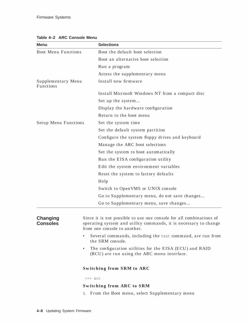
Firmware Systems
Table 4–2 ARC Console Menu
Menu Selections
Boot Menu Functions Boot the default boot selection
Boot an alternative boot selection
Run a program
Access the supplementary menu
Supplementary MenuFunctions
Install new firmware
Install Microsoft Windows NT from a compact disc
Set up the system...
Display the hardware configuration
Return to the boot menu
Setup Menu Functions Set the system time
Set the default system partition
Configure the system floppy drives and keyboard
Manage the ARC boot selections
Set the system to boot automatically
Run the EISA configuration utility
Edit the system environment variables
Reset the system to factory defaults
Help
Switch to OpenVMS or UNIX console
Go to Supplementary menu, do not save changes...
Go to Supplementary menu, save changes...
ChangingConsoles
Since it is not possible to use one console for all combinations ofoperating system and utility commands, it is necessary to changefrom one console to another.
• Several commands, including the test command, are run fromthe SRM console.
• The configuration utilities for the EISA (ECU) and RAID(RCU) are run using the ARC menu interface.
Switching from SRM to ARC
>>> arc
Switching from ARC to SRM
1. From the Boot menu, select Supplementary menu
4–8 Updating System Firmware

Firmware Systems
2. From the Supplementary menu, select Set up the System ...
3. From the Setup menu, select Switch to OpenVMS or DigitalUNIX console.
4. Select your operating system console, then select the Setupmenu and press Enter
5. When the "Power-cycle the system to implement the change"message is displayed, press the Reset button.
When the console system is loaded and the system is initialized,the SRM console prompt
>>>
is displayed.
FirmwareVersion
The operating system is dependent on the console system forits interface to the hardware, and subsequent correct behavior.Therefore it is critical to use the console system at the definedrevision level for the version of the operating system being used.
Actually there are three factors to consider when determining thefirmware version to use:
• Operating system type and version
• Firmware revision
• Hardware platform
So one starting point is found in the installation manual forthe operating system under consideration. For Digital UNIXV4.0, consult the Digital UNIX Installation Guide Chapter 1,Installation Overview and Preinstallation Tasks. Find the tablewhich lists the minimum firmware level for each Alpha systemtype.
An alternative method is to use the Firmware Update Proceduresdocument associated with the hardware platform. This documentis on the firmware CD ROM and lists the firmware revision forthe platform with corresponding operating system versions whichit will support.
If your system is not at the minimum firmware level, you mustupdate the firmware prior to building the new operating system.
UpdateFirmwareProcess
Digital distributes console firmware whenever the operatingsystem is updated or as is required. To run Digital UNIX V4.0your system might require a firmware update. Firmware updatesare found on the Alpha Systems Firmware CD–ROM compact discthat is included with your Digital UNIX media kit.
The first step of the upgrade is to read the documentationprovided:
Updating System Firmware 4–9
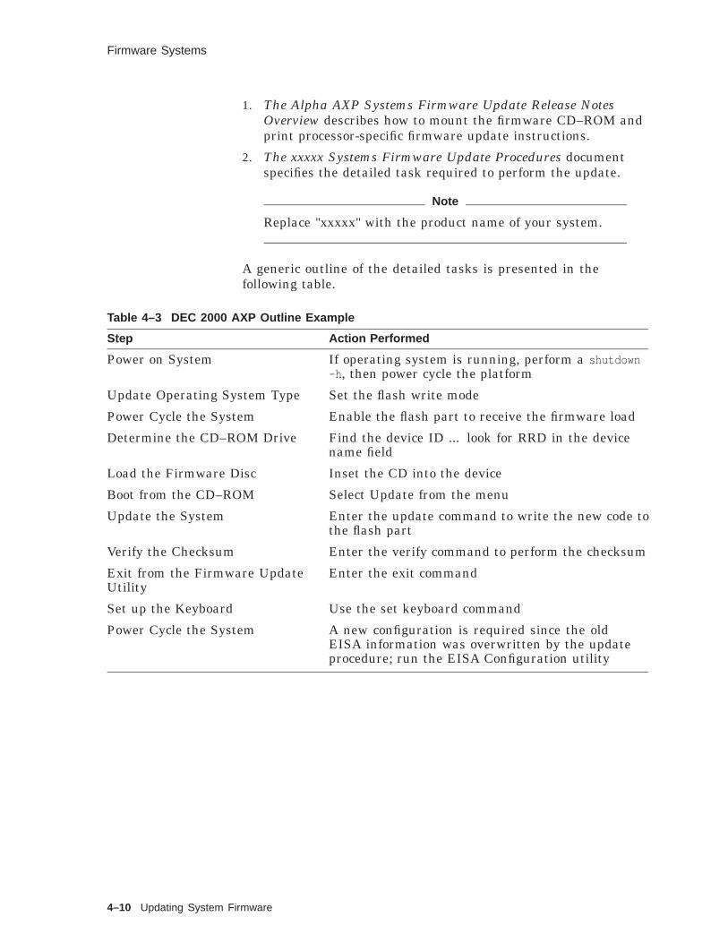
Firmware Systems
1. The Alpha AXP Systems Firmware Update Release NotesOverview describes how to mount the firmware CD–ROM andprint processor-specific firmware update instructions.
2. The xxxxx Systems Firmware Update Procedures documentspecifies the detailed task required to perform the update.
Note
Replace "xxxxx" with the product name of your system.
A generic outline of the detailed tasks is presented in thefollowing table.
Table 4–3 DEC 2000 AXP Outline Example
Step Action Performed
Power on System If operating system is running, perform a shutdown-h , then power cycle the platform
Update Operating System Type Set the flash write mode
Power Cycle the System Enable the flash part to receive the firmware load
Determine the CD–ROM Drive Find the device ID ... look for RRD in the devicename field
Load the Firmware Disc Inset the CD into the device
Boot from the CD–ROM Select Update from the menu
Update the System Enter the update command to write the new code tothe flash part
Verify the Checksum Enter the verify command to perform the checksum
Exit from the Firmware UpdateUtility
Enter the exit command
Set up the Keyboard Use the set keyboard command
Power Cycle the System A new configuration is required since the oldEISA information was overwritten by the updateprocedure; run the EISA Configuration utility
4–10 Updating System Firmware

Summary
Summary
DigitalFirmwareSystems
The firmware system is the layer that interfaces between thehardware and the operating system. It also provides the consolefunctions to support the operating system and the low leveloperator functions such as:
• Initialize, test, and prepare the system platform
• Provide boot options
• System control and monitoring
Digital firmware supports the following operating systems:
• Digital OpenVMS
• Digital UNIX
• Microsoft Windows NT
Architecture On Alpha systems, the console firmware system is loaded bydefault when the platform is powered on. This system definesthree general areas of functionality for a given system:
• Hardware configuration and test
• User control
• Software bootstrap
SRM This is the architectural standard defined to support DigitalUNIX, OpenVMS, and ELX (VMS realtime system) operatingsystems. It is used by the operating system to communicate withthe hardware control functions. SRM specifies the requirementsprocedural tasks and the format of critical data structures.
ARC This console supports the architectural standard subscribed toand required for the Windows NT operating system. Includedin the standards are requirements for system components,subsystem interfaces, and the hardware abstraction layer.
ChangingConsoles
Since it is not possible to use one console for all combinations ofoperating system and utility commands, it is necessary to changefrom one console to another.
• Several commands, including the test command, are run fromthe SRM console.
• The configuration utilities for the EISA (ECU) and RAID(RCU) are run using the ARC menu interface.
Updating System Firmware 4–11

Summary
FirmwareVersion
The operating system is dependent on the console system forits interface to the hardware, and subsequent correct behavior.Therefore it is critical to use the console system at the definedrevision level for the version of the operating system being used.
Actually there are three factors to be considered whendetermining the firmware version to be used:
• Operating system type and version
• Firmware revision
• Hardware platform
4–12 Updating System Firmware
Exercises
Exercises
ValidateVersion
1. Determine the firmware version currently running on yoursystem. Is it valid for use with Digital UNIX Version 4.0?
2. Planning and implementation of the next operating systemrelease requires a detailed configuration of the EISA deviceson your system. You must interrupt a normal multiuseroperating system to get the information.
Updating System Firmware 4–13

Solutions
Solutions
ValidateVersion
1. These are the steps to determine the firmware version:
a. At the console prompt, type the command show version
b. Verify firmware version against Chapter 1 of the DigitalUNIX Installation Guide
2. These are the steps to obtain the configuration information:
a. shutdown -h +60 shutting down for 10 minutes
b. arc
c. Access the supplementary menu
d. Access the setup menu
e. Run the EISA configuration utility
f. Return to the supplementary menu without saving changes
g. Return to the boot menu
h. Boot the default selection
4–14 Updating System Firmware

5Installing the System
Installing the System 5–1

About This Chapter
About This Chapter
Introduction This chapter discusses the decision making, planning, andprocedures that must be accomplished prior to actually initiatinginstallation of the operating system.
This chapter shows you how to invoke the new Common DesktopEnvironment (CDE) installation process using the CDE GUI tool.
This chapter also describes the characteristics of both thedefault and custom installation types and discusses how theseinstallations are performed.
Finally, this chapter describes how to perform an updateinstallation and how to make adjustments to files after completingthe update installation process.
Objectives To install the Digital UNIX operating system, you should be ableto:
• Plan and prepare for an installation
• Invoke the CDE windows setup procedure and demonstrate anawareness of the tools and utilities offered under this option
• Perform an update installation
Resources For more information on the topics in this chapter, see thefollowing:
• Digital UNIX Installation Guide
• Digital UNIX Release Notes
• Digital UNIX Operating System Version 4.0 SPD
5–2 Installing the System

Preparing for an Installation
Preparing for an Installation
Overview This section discusses the characteristics of the default, custom,and update installation procedures.
Depending on your needs, you can perform a default, a custom,or an update installation. See the installation decision tree inChapter 1 of the Digital UNIX Installation Guide.
In addition to deciding on the installation type, you mustcomplete the following steps before starting any operating systeminstallation:
1. Always review the Release Notes. The Release Notes identifyany last-minute changes to the software.
2. See the Digital UNIX Operating System Version 4.0 to verifythat you have the hardware required for installation.
3. If you are installing on a working system, back up the system.
4. Inventory the contents of the software distribution kit.
5. Review your system hardware and the Digital UNIXInstallation Guide Chapter 1 documentation to determine if afirmware upgrade is required.
6. If you are doing a custom installation of Digital UNIX,plan your disk space. A complete list of all subset(s) andcorresponding space required can be found in Appendix E ofthe Digital UNIX Installation Guide.
InstallationMedia Types
Use the following distribution media for any of the installationtypes.
• A CD–ROM optical disc
• Remote Installation Services (RIS)
Planning DiskSpace
Deciding between a Default and Custom installation is really amatter of assessing your system assets (available memory anddisk space) and your installation requirements. A major partof this process involves planning your disk space requirements.This is thoroughly discussed in the Planning Disk Space chapterof the Digital UNIX Installation Guide. This chapter providesworksheets that help you:
• Identify available disks
• Plan the swap space
• Plan the /var area
• Plan the /usr file system
Installing the System 5–3

Preparing for an Installation
• Decide whether to use the default disk partition layout or theexisting disk partition layout, and change the partition layout,if necessary.
Planning SwapSpace
The Digital UNIX Installation Guide suggests that the swapspace should be at least the size of the processor’s physicalmemory. In practice, this is just not enough swap space. If youhave more that a few processes running, you will quickly run outof swap space. You should allocate two to three times the size ofthe processor’s physical memory for swap space. Since partitionsizes are specified in blocks, and there are 2048 blocks to 1 Mbyte,if you have 32 Mbytes of physical memory, you would allocate:
32 x 2048= 65,536x 2
------131,072 Blocks allocated for swap space
DefaultInstallation
The default installation will automatically size the default diskfor the correct storage required and then performs the installationin this manner:
• Provides by default the UFS file system layout
• Allocates 64 MB of disk space for the root file system onpartition a
• Allocates the b partition for dumps and swap space
• Allocates the g partition of the disk for the /usr and /var filesystem
• Loads the mandatory software subsets
Select the default installation if you do not need to:
• Preserve custom partition tables or disklabels. Custompartition tables are partition tables that have been changed tosizes other that the default values.
• Allocate the /usr file system on a separate disk.
• Allocate a separate /var file system.
• Allocate a second swap space.
• Install optional software at this time.
If necessary, you can install additional software subsets afterthe initial installation, by using the setld utility. See SystemAdministration for information on installing software subsetsafter the installation.
5–4 Installing the System

Preparing for an Installation
CustomInstallation
With the custom installation, you can:
• Select the default disk partitions and the default file systemlayout, or you can decide on which disks you want the filesystems to reside.
• Allocate disk space for the root file system.
• Choose to install some or all of the optional subsets. Makesure there is enough disk space to install all optional subsetsin the /usr file system.
The mandatory subsets are automatically installed.
Choose the custom installation only if you need to perform any ofthe following tasks:
• Preserve custom partition tables or disk labels
• Select file system layouts other than the defaults
• Allocate the /usr file system to a specific disk partition
• Allocate more than one swap area
• Allocate the /var area to the same disk partition as /usr or toa different disk partition
• Add optional supported software subsets
UpdateInstallation
The update installation has the following characteristics:
• Preserves disk partitions
• Preserves file systems
• Leaves user files added to the system intact
• Merges user-customizations into protected system files
• Detects, logs, and saves unprotected user-customized systemfiles
• Detects and logs obsolete files
The update installation updates:
• All Version 3.2C mandatory and optional subsets installed onthe system.
• New Digital UNIX Version 4.0 mandatory subsets
Caution
Once you start an update installation, you cannot stop it.If you do, you are likely to lose system files.
New Digital UNIX optional subsets must be added with the setldutility after the installation update completes.
The old subset information in /usr/.smdb. gets deleted.
Installing the System 5–5

Preparing for an Installation
The update installation installs from either a CD–ROM or a RISserver.
HardwareRequired forInstallation
Installation of the Digital UNIX operating system requires someor all of the following hardware:
• Software distribution device corresponding with the softwaredistribution media. If you are installing from the RIS area,see your server administrator for instructions.
• Ethernet for RIS installation
• System disk (required)
• Data disks (optional). In some cases, you do not need datadisks to install the Digital UNIX operating system. Note,however, that if you perform a custom installation, you canallocate certain file systems to a disk other than the systemdisk.
• Console terminal (required): Use the console terminalto communicate with the system during the installation.Depending on the system configuration, you can perform theinstallation at either a serial hardcopy terminal, a serial videoterminal, or at the console display if the system is a graphicsworkstation.
Booting fromthe Media
The initial boot to build the new system from the CD–ROMdistribution media requires you to use the CD–ROM disk. Thefollowing command may be issued on the running system todetermine the correct device.
# file /dev/rrz*c
There is more than one type of device depending on the platformtype, but all devices will have a common component (RRD) anddevice type component (xx).
RRDxx
Alternately you may identify the CD–ROM device when thesystem is halted at the console prompt with the command
>>> sh device
The booting procedure varies according to the platform. Consultthe Digital UNIX Installation Guide Chapter 4 for the exactprocedure. Appendix A of the same guide provides the procedurefor mounting and unmounting the media.
You may also boot over the network from the Remote InstallationServer (RIS), again refer to Chapter 4 for instructions.
5–6 Installing the System

Common Desktop Installation
Common Desktop Installation
Overview This environment provides a windows-based graphical userinterface for the initial phases of an installation as well as systemmanagement activities such as changing the root disk partitionlayout prior to performing a custom installation.
Note that a graphic capable console is required. A character cellinterface is provided for character cell based consoles.
Figure 5–1 Initiating an Installation
Root:Partition
Device Name
File System Type
DiskType
DiskNumber
Controller Type
Controller Number
Setup Done View Software UNIX Shell Help
Device, Partition, and File System Selection:
Partition Disks
Install Type: Date: − − (mm−dd−yy)Default
(hh:mm:24 hr Format)
SDI−DW−01−RGS
Installation Setup
<Ret>
<Ret>
:Host Name:
Root Password:
Verify Password:
Time:
Location:
Time Zone:
This installation setup window is automatically invoked afterbooting from the installation media. Instructions are found inChapter 4 of the Installation Guide - Booting Your Processor orSingle-Board Computer.
Hint
Two pieces of information are needed to get started withthe boot: system type and the disk configuration. Theseconsole commands can be used:
• show device displays disk info
Installing the System 5–7

Common Desktop Installation
• show config displays the system type
CommonDesktopEnvironment
The common desktop environment is a new graphical userbased interface which also has an installation component. Thiscomponent is automatically invoked when the system is bootedfrom the distribution media in either of two methods:
• Using the CD–ROM media disk 1 of 3
• Using the remote installation (RIS) technique
When the system boots, the user first sees a Pop-up windowdisplay as evidence of a successful boot.
Figure 5–2 Status Window
Loading Keyboard Map ...
Scanning System HardwarePlease wait ...
sdi−dw−04−rgs
DefaultInstallation
The next display is the installation setup window which sets thedesired installation parameters. The default type of installationis automatically selected as the Default, as shown in the setupwindow illustration. The user is required to enter only thecommon setup parameters as noted previously.
At this point the installation manager will check that thedefault disk has the required capacity to continue the defaultconfiguration process. Next, the calculated values are displayedfor the device, partition, and file system selection parameters.
5–8 Installing the System

Common Desktop Installation
Figure 5–3 Default Parameters
Root:Partition
Device Name
File System Type
DiskType
Disk ControllerNumber Type
Controller Number
Setup Done View Software UNIX Shell Help
Device, Partition, and File System Selection:
Partition Disks
Install Type: Date: − − (mm−dd−yy)Default
(hh:mm:24 hr Format)
sdi−dw−02−rgs
Installation Setup
<Ret>
<Ret>
:Host Name:
Root Password:
Verify Password:
Time:
Location:
Time Zone:
rz0 UFS rz25 0 SCSI 0a
Common SetupFeatures
Regardless of the type of installation selected, a common set ofparameters are required:
• Host Name
• Root Password
• Verify Password
• Date
• Time
• Location
• Time Zone
Since all parameters are now defined by the user and the defaultconfiguration process, the user may now click the Setup Donebutton to continue the automatic configuration of the system. APop-up window appears where the user is prompted to start theinstallation by clicking OK.
Installing the System 5–9
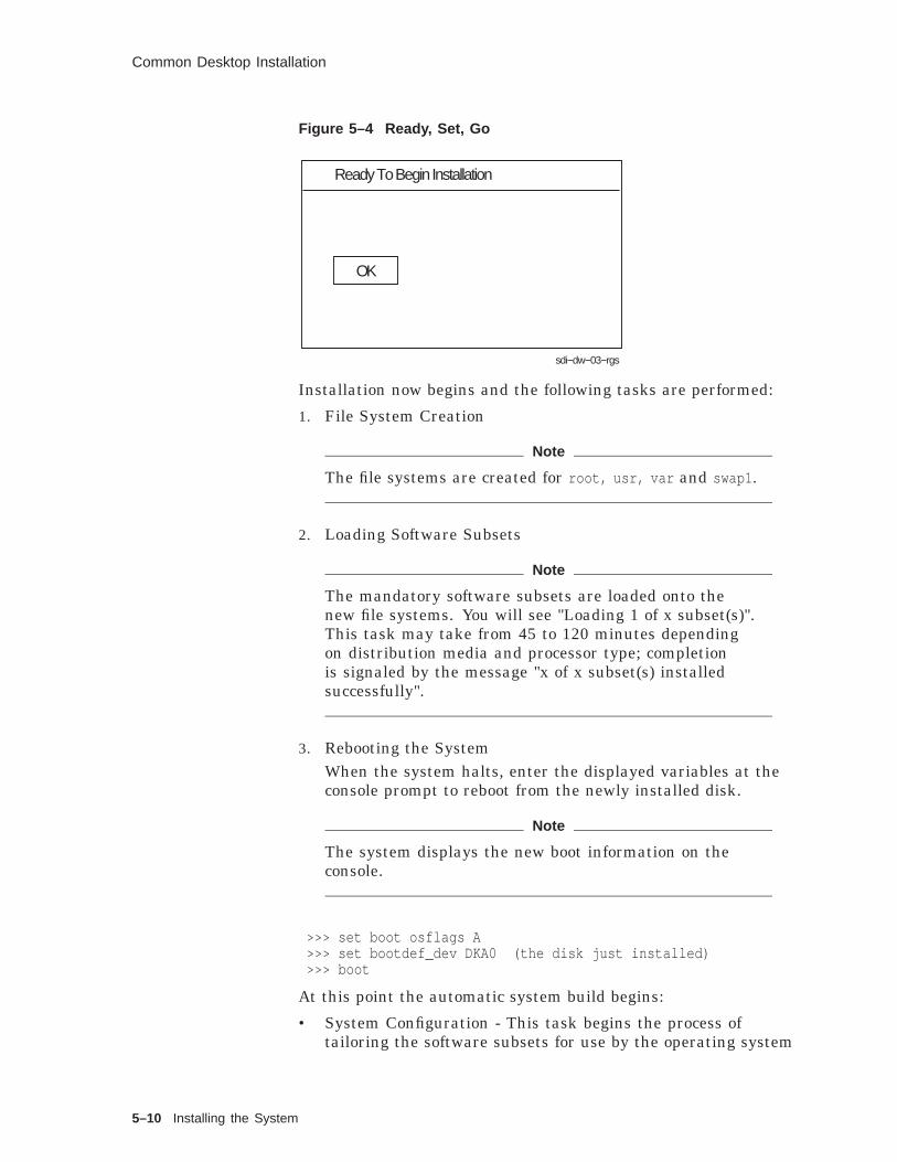
Common Desktop Installation
Figure 5–4 Ready, Set, Go
Ready To Begin Installation
OK
sdi−dw−03−rgs
Installation now begins and the following tasks are performed:
1. File System Creation
Note
The file systems are created for root, usr, var and swap1 .
2. Loading Software Subsets
Note
The mandatory software subsets are loaded onto thenew file systems. You will see "Loading 1 of x subset(s)".This task may take from 45 to 120 minutes dependingon distribution media and processor type; completionis signaled by the message "x of x subset(s) installedsuccessfully".
3. Rebooting the SystemWhen the system halts, enter the displayed variables at theconsole prompt to reboot from the newly installed disk.
Note
The system displays the new boot information on theconsole.
>>> set boot osflags A>>> set bootdef_dev DKA0 (the disk just installed)>>> boot
At this point the automatic system build begins:
• System Configuration - This task begins the process oftailoring the software subsets for use by the operating system
5–10 Installing the System

Common Desktop Installation
and the hardware. Console messages are displayed as eachsubset is processed.
• Kernel Build - The kernel is now built automatically and theuser is then prompted to boot the new operating system.
CustomInstallation
A custom installation is warranted when the disks, partitions, filesystems, and software to be loaded require tailoring.
Note that the common parameters described in the previousDefault Installation section, also apply in this case. So we willbegin discussion with the parameters needed to provide thedesired customizations.
First we consider the setup of the disks.
Figure 5–5 Custom Installation
Root:Partition
Device Name
File System DiskType Type
Disk ControllerNumber
Controller Number Type
Device, Partition, and File System Selection:
Install Type: Date: − − (mm−dd−yy)Custom
(hh:mm:24 hr Format)
sdi−dw−05−rgs
Installation Setup
<Ret>
<Ret>
:
Usr:
Var:
Swap1:
Swap2:
Host Name:
Root Password:
Verify Password:
Time:
Location:
Time Zone:
Setup Done View Software UNIX Shell HelpPartition Disks
rz0
rz0
In/Usr
rz0
rz1
a
g
b
b
UFS
UFS
UFS
UFS
rz25
rz25
rz25
rz25
0
0
0
1
SCSI
SCSI
SCSI
SCSI
0
0
0
0
To enable the custom menus, click Custom in the Install Type:entry field. This causes the display to change so that all variablesare displayed.
Installing the System 5–11

Common Desktop Installation
• Root
• Usr
• Var
• Swap1
• Swap2
Simply key in the desired parameters for each category. Forinformation on planning considerations, see Chapter 3 of theInstallation Guide.
View Software Click the View Software button to display the Software Selectionwindow. The user can examine the mandatory and optionalsoftware subsets, and also select the optional subsets to beloaded.
Figure 5–6 Selecting Software
sdi−dw−swsel.eps
Software Selection
Help
Remove All
OK Cancel
Add All
Remove
Add
Available Software:
Selected Software::
File System Status:
General Applications
Additional Terminfo Databases
root: 28.1 MB free usr: 298 MB free
Computer Aided System Tutor
var:
DOS Tools
free
GNU Emacs
− Required −
(MANDATORY) Base System
(MANDATORY) Base System − Hardware Support
General Applications
Local Area Transport (LAT)
(MANDATORY) Tcl Commands
5–12 Installing the System
Common Desktop Installation
Installation is enhanced by using this new graphic techniqueto display the software subsets which are mandatory as wellas optional. Note the (MANDATORY) subset indicator in theSelected Software list box. Optional software is shown in theAvailable Software list box. To select optional software:
1. Select the software subset from the Available Software listbox.
2. Click the Add button.
Optionally you may add all of the optional software. Note thatthe Remove All button will remove all the optional software, butnot the mandatory software.
Particularly useful is the File System Status area. Root and usrfile system available space is automatically recalculated for eachsoftware subset when it is added. If the file system free space isconsumed, you may remove specific subsets or cancel the selectionentirely. The Cancel button will place you back at the InstallationSetup window where you may change the disk and partitionparameters to store the required software.
Partition Disks Clicking the Partition Disks button displays a window in whichthe partitions of a disk can be viewed or altered. Note that thisis a CDE version of the disklabel program to manage disks.The CDE interface allows you to navigate, view and alter diskpartitions using the mouse versus the disklabel program whereyou enter commands and options.
Installing the System 5–13

Common Desktop Installation
Figure 5–7 Disk Parameters
Root:Partition
Device Name
File System DiskType Type
Disk ControllerNumber
Controller Number Type
Device, Partition, and File System Selection:
Install Type: Date: − − (mm−dd−yy)Custom
(hh:mm:24 hr Format)
sdi−dw−05−rgs
Installation Setup
<Ret>
<Ret>
:
Usr:
Var:
Swap1:
Swap2:
Host Name:
Root Password:
Verify Password:
Time:
Location:
Time Zone:
Setup Done View Software UNIX Shell HelpPartition Disks
rz0
rz0
In/Usr
rz0
rz1
a
g
b
b
UFS
UFS
UFS
UFS
rz25
rz25
rz25
rz25
0
0
0
1
SCSI
SCSI
SCSI
SCSI
0
0
0
0
Partitions may be modified using the GUI-based window shownhere. All the necessary parameters are displayed for the user.
5–14 Installing the System

Common Desktop Installation
Figure 5–8 Configure Partitions
UNIX Shell Clicking the UNIX Shell button in the Installation Setupwindow places the system in single user mode with superuserprivileges. This option is provided for experienced UNIXsystem administrators who want to perform file system or diskmaintenance tasks prior to the installation. The capabilities ofthe shell are:
• Edit a file using ed or vi text editors.
• Create new file systems.
• Restore file systems.
• Modify partition tables.
• Mount other disks and file systems.
• Repair UFS file systems.
Refer to Chapter 7 of the Installation Guide for commands andoperational procedures for maintenance tasks.
Creating theOperatingSystem
When you have configured the disks, partitions, and file systems,as well as the section of optional software to load, you are nowready to begin the installation by clicking Setup Done. Thefollowing example continues the custom installation, loadingonly the mandatory software subsets and illustrates the consoleoutput.
Installing the System 5–15

Common Desktop Installation
Example 5–1 Creating the Operating System
*** Creating the root file system on device rz3a ***
*** Creating the usr file system on device rz3g ***
*** Creating the var file system on device rz3h ***
*** Creating the swap1 file system on device rz2b ***
*** Loading the operating system software subsets ***
The installation procedure will now load the software on yourdisk partitions. This process will take from 45 to 120 minutesto complete depending on your distribution media and processor type.
Checking file system space required to install specified subsets:Working....Tue Mar 28 17:08:46 EST 1995
File system space checked OK.
29 subset(s) will be installed.
Loading 1 of 29 subset(s)....
Base SystemCopying from /ALPHA/BASE (disk)
Working....Tue Mar 28 17:09:02 EST 1995Working....Tue Mar 28 17:11:04 EST 1995Working....Tue Mar 28 17:13:06 EST 1995Working....Tue Mar 28 17:15:08 EST 1995Working....Tue Mar 28 17:17:09 EST 1995
VerifyingWorking....Tue Mar 28 17:18:46 EST 1995
Loading 2 of 29 subset(s)....
Base System - Hardware SupportCopying from /ALPHA/BASE (disk)
Working....Tue Mar 28 17:19:44 EST 1995Verifying
.
.
.Loading 29 of 29 subset(s)....
Graphical Print Configuration ApplicationCopying from /ALPHA/BASE (disk)Verifying
29 of 29 subset(s) installed successfully.
Install start: Tue Mar 28 17:04:10 EST 1995Install finish: Tue Mar 28 18:08:09 EST 1995
Issue the following console commands to set your default bootpath variableand to boot your system disk to multiuser:
>>> set boot_osflags A>>> set bootdef_dev "DKA300">>> boot
Booting theNew OperatingSystem
At this point the new operating system has been built with theparameters listed on the console output in the previous example.You must enter the boot parameters and boot the new system.
5–16 Installing the System

Common Desktop Installation
KernelConfiguration
After the new system is booted, the kernel configuration and buildprocedure begins. You will be prompted to select kernel options.
-------------------------------------------------------------------------%IT START% Thu Feb 29 12:55:40 EST 1996
-------------------------------------------------------------------------
swapon: /dev/rz3b: already a swap deviceswapon: adding /dev/rz3b as swap device.
*** SYSTEM CONFIGURATION ***
Configuring "Base System " (OSFBASE400)
Configuring "Base System - Hardware Support " (OSFHWBASE400)
Configuring "Compiler Back End " (OSFCMPLRS400)
Configuring "Kernel Header and Common Files " (OSFBINCOM400)
Configuring "Standard Kernel Modules " (OSFBIN400)
Configuring "Hardware Kernel Header and Common Files" (OSFHWBINCOM400)
Configuring "Hardware Kernel Modules " (OSFHWBIN400)
Configuring "Basic Networking Services " (OSFCLINET400)...
Configuring "Graphical System Administration Utilities" (OSFXADMIN400)
Configuring "Graphical Print Configuration Application" (OSFXPRINT400)
Configuring "Ref Pages: Admin/User " (OSFMANOS400)
Configuring "Ref Pages: Windows Admin/User " (OSFMANWOS400)
Configuring "Ref Pages: Realtime " (OSFMANRT400)
Configuring "Ref Pages: Programming " (OSFMANOP400)
Configuring "Ref Pages: Windows Programming " (OSFMANWOP400)
Configuring "Ref Pages: CDE Development " (OSFCDEMANOP400)
Configuring "Ref Pages: CDE Admin/User " (OSFCDEMANOS400)
The system name assigned to your machine is ’vrroom’.
*** KERNEL CONFIGURATION AND BUILD PROCEDURE ***
*** KERNEL OPTION SELECTION ***
Installing the System 5–17

Common Desktop Installation
Selection Kernel Option--------------------------------------------------------------
1 System V Devices2 Logical Volume Manager (LVM)3 NTP V3 Kernel Phase Lock Loop (NTP_TIME)4 Kernel Breakpoint Debugger (KDEBUG)5 Packetfilter driver (PACKETFILTER)6 Point-to-Point Protocol (PPP)7 STREAMS pckt module (PCKT)8 X/Open Transport Interface (XTISO, TIMOD, TIRDWR)9 File on File File System (FFM)10 ISO 9660 Compact Disc File System (CDFS)11 Audit Subsystem12 ACL Subsystem13 All of the above14 None of the above15 Help
--------------------------------------------------------------
Enter the selection number for each kernel option you want.For example, 1 3 [14]: 6
You selected the following kernel options:
Point-to-Point Protocol (PPP)
Is that correct? (y/n) [y]: y
Do you want to edit the configuration file? (y/n) [n]:
The system will now automatically build a kerneland then reboot. This will take approximately 15minutes, depending on the processor type.
When the login prompt appears after the systemhas rebooted, use ’root’ as the login name andthe SUPERUSER password that was entered duringthis procedure, to log into the system.
*** PERFORMING KERNEL BUILD ***Working....Thu Feb 29 13:01:10 EST 1996Working....Thu Feb 29 13:03:11 EST 1996
Error opening license database /var/adm/lmf/ldblmf: No such file or directory
-------------------------------------------------------------------------%IT STOP% Thu Feb 29 12:55:40 EST 1996
-------------------------------------------------------------------------
PostInstallationLogin andSetup
When you log in to the system (with graphics capability) for thefirst time, the CDE login window is displayed. Enter root asthe username and then enter the root password specified at thebeginning of the installation. The display window created hasfour components:
• A Help Viewer window, Introducing the Desktop
• A Pop-up window labeled: Action Required
5–18 Installing the System

Common Desktop Installation
• A post-install Configuration Checklist window
• The CDE Front Panel appears at the bottom of your screen
Note
These components are explained in Chapter 6 of theDigital UNIX Installation Guide.
The catman command creates formatted versions of the onlinereference pages and creates the source files for the whatisdatabase. By invoking the catman command, you will improve theperformance of viewing reference pages and will keep the whatisdatabase up-to-date. The apropos command also uses the whatisdatabase to display appropriate commands. See the catman (8) formore information on how to use the command.
Installing the System 5–19

Performing an Update Installation
Performing an Update Installation
Overview The update installation is for Alpha systems running DigitalUNIX Version V3.2C or later. This upgrade installation processwill also be used in future releases of the operating system.
You can initiate an update installation by running theinstallupdate utility. Before you run this utility, there are anumber of conditions and restrictions you need to be aware of:
• Your current system must be running Digital UNIX Version3.2C or later.
• You have upgraded your firmware appropriately.
• There can be no changes of symbolic links to directoriesor conversely, no location changes of directories that havesymbolic links.
• Certain layered products will cause the update installation toquit. You need to remove these layered products before doingan update installation:
DECnet
Internationalization
Open 3D
• You must have enough disk space.
Update InstallFile Types
You need to be aware of the file types that the update installationutility works with during and after the software is installed. Thefile types are:
• Protected Customized System Files
• Version 3.2C system files that are automatically merged withVersion 4.0
• File prefix is .new..filename. The .mrg..filename is used toperform protected system file merges.
• Any customizations you have made to V3.2C versions ofprotected system files are merged with Version 4.0.
• Unprotected Customized System Files
Version 3.2C files that are not merged with Version 4.0files.
These files are saved with the extension .PreUPD.
File names get stored in /var/adm/smlogs/upd_custom_files .
5–20 Installing the System

Performing an Update Installation
You must manually merge file customizations. To performadministrative tasks on these files, use the updadmin utility.
• Obsolete System Files
System files no longer shipped with operating system.
File names stored in /var/adm/smlogs/upd_obsolete_files .
Characteristicsof an UpdateInstallation
The update installation has the following characteristics:
• Preserves disk partitions
• Preserves file systems
• Leaves user files added to the system intact
• Merges user-customizations into protected system files
• Detects, logs, and saves unprotected user-customized systemfiles
• Detects and logs obsolete files
The update installation updates:
• All Version 3.2C mandatory and optional subsets installed onthe system.
• New Digital UNIX Version 4.0 mandatory subsets
Caution
Once you start an update installation, you cannot stop it.If you do, you are likely to lose system files.
New Digital UNIX optional subsets must be added with the setldutility after the installation update completes.
The old subset information in /usr/.smdb. gets deleted.
The update installation installs from either a CD–ROM or a RISserver.
UpdateInstallationProcedure
An update installation creates the log file:
/var/adm/smlogs/update.log
The example shows a /var/adm/smlogs/update.log .
Example 5–2 Update Installation Log
#shutdown +5 Performing Update Installation 1#swapon -e 2#bcheckrc 3#/sbin/installupdate /dev/rz4c
or 4#/sbin/installupdate /cdmnt
(continued on next page)
Installing the System 5–21
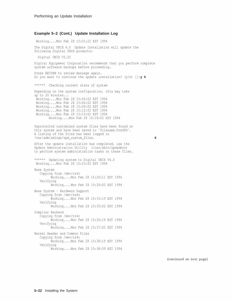
Performing an Update Installation
Example 5–2 (Cont.) Update Installation Log
Working....Mon Feb 28 15:01:22 EST 1994
The Digital UNIX 4.0 Update Installation will update thefollowing Digital UNIX products:
Digital UNIX V3.2C
Digital Equipment Corporation recommends that you perform completesystem software backups before proceeding.
Press RETURN to review message again.Do you want to continue the update installation? (y/n) []: y 5
****** Checking current state of system
Depending on the system configuration, this may takeup to 20 minutes...
Working....Mon Feb 28 15:04:02 EST 1994Working....Mon Feb 28 15:06:02 EST 1994Working....Mon Feb 28 15:08:02 EST 1994Working....Mon Feb 28 15:12:02 EST 1994Working....Mon Feb 28 15:15:02 EST 1994
Working....Mon Feb 28 15:18:02 EST 1994
Unprotected customized system files have been found onthis system and have been saved to ’filename.PreUPD’.A listing of the files has been logged in/var/adm/smlogs/upd_custom_files. 6
After the update installation has completed, use theUpdate Administration Utility (/usr/sbin/updadmin)to perform system administration tasks on these files.
****** Updating system to Digital UNIX V4.0Working....Mon Feb 28 15:23:02 EST 1994
Base SystemCopying from /dev/rz4c
Working....Mon Feb 28 15:26:11 EST 1994Verifying
Working....Mon Feb 28 15:28:02 EST 1994
Base System - Hardware SupportCopying from /dev/rz4c
Working....Mon Feb 28 15:33:19 EST 1994Verifying
Working....Mon Feb 28 15:35:02 EST 1994
Compiler BackendCopying from /dev/rz4c
Working....Mon Feb 28 15:36:19 EST 1994Verifying
Working....Mon Feb 28 15:37:02 EST 1994
Kernel Header and Common FilesCopying from /dev/rz4c
Working....Mon Feb 28 15:38:19 EST 1994Verifying
Working....Mon Feb 28 15:38:59 EST 1994
(continued on next page)
5–22 Installing the System

Performing an Update Installation
Example 5–2 (Cont.) Update Installation Log
Standard Kernel ObjectsCopying from /dev/rz4c
Working....Mon Feb 28 15:40:09 EST 1994Verifying
Working....Mon Feb 28 15:41:12 EST 1994
Hardware Kernel ObjectsCopying from /dev/rz4c
Working....Mon Feb 28 15:42:29 EST 1994Verifying
Working....Mon Feb 28 15:43:22 EST 1994
Basic Networking ServicesCopying from /dev/rz4c
Working....Mon Feb 28 15:44:23 EST 1994Verifying
Working....Mon Feb 28 15:46:11 EST 1994
X ServersCopying from /dev/rz4c
Working....Mon Feb 28 15:47:17 EST 1994Verifying
Working....Mon Feb 28 15:49:19 EST 1994
Basic X EnvironmentCopying from /dev/rz4c
Working....Mon Feb 28 15:51:33 EST 1994Verifying
Working....Mon Feb 28 15:55:24 EST 1994
.
. 7
.CDA(tm) for X/Motif Development
Copying from /dev/rz4cVerifying
*** Merging new file ./.new..DXsession intoexisting ./.proto..DXsession
Merge completed successfully
*** Merging new file ./etc/.new..gettydefs intoexisting ./etc/.proto..gettydefs
*** Merging new file ./etc/.new..securettys intoexisting ./etc/.proto..securettys
Merge completed successfully
*** Merging new file ./usr/share/lib/.new..termcap intoexisting ./usr/share/lib/.proto..termcap
.
.
.
Merge completed successfully.
Update Installation complete.rebooting system... 8
1 Shut the system down to single user mode.
Installing the System 5–23
Performing an Update Installation
2 Start system swapping.
3 Mount the local file systems. If you already have a mountinstruction in your /etc/fstab file, you can skip this step.
4 Invoke the installupdate utility. Two ways are shown in theprocedure; one using the CD–ROM device, and another usinga CD–ROM mount point. See the Digital UNIX InstallationGuide for additional instructions to install from a RIS server.
5 The utility displays a reminder to back up your system andasks you if you want to continue.
6 The utility notes unprotected customized system files(*.PreUPD files) and logs their names in the /var/adm/smlogs/upd_custom_files .
7 Partial listing to save paper.
8 The utility sends an Update Installation complete messageand reboots the system.
The installupdate program next runs the IT utility to upgradethe configuration as described in the /var/adm/smlogs/it.log .Review the /var/adm/smlogs/it.log sample in the Digital UNIXInstallation Guide. Because the system name, date and timehave been specified in a previous installation, the IT utility skipsthese configuration questions and begins configuring the softwareimmediately.
UpdateAdministrationUtility
The Update Administration utility enables you to manage:
• Protected system files
• Unprotected system files
• Obsolete files
You can save, delete, or view any of these file types.
If you choose to save files, the updadmin utility lets you save filesto a directory on disk, to a tar image on disk, or to a tape mediadevice. Review the updadmin utility in the Performing and UpdateInstallation chapter of the Digital UNIX Installation Guide.
Run the Update Administration utility after the updateinstallation configuration event has occurred. The command youenter is:
#/usr/sbin/updadmin
upadmin MainMenu
The utility displays a main menu:
Update Administration Utility Main Menu---------------------------------------c) Update Customized File Administrationo) Obsolete System File AdministrationP) PreMRG File Administrationx) Exit this utility:
5–24 Installing the System

Performing an Update Installation
You can save, delete, or view any of these three file types.
If you decide to save files, the utility lets you save files to adirectory on a disk, to a tar image on a disk, or to a tape mediadevice.
If you decide to delete files, the utility checks to see if you havesaved the files. If you have not saved the files, the utility givesyou the option to save the files before deleting them.
The view option displays information on each file based on thetype of file administration you are performing.
CustomizedSystem FileAdmin Menu
If you choose to manage Unprotected Customized System files,updadmin displays a short message and the menu:
Unprotected Customized System File Admin Menu---------------------------------------------s) Save filesd) Delete filesv) View list of filesx) Return to previous menu
Enter your choice:
The other file type choices yield a different message, but similarmenu items.
Saving, deleting, and viewing the various file types is discussedfurther.
Saving Files If you choose the Save Files menu option (s), updadmin displaysthe menu:
Select a method of archiving your files:---------------------------------------d) Save files to directory on diski) Save files to tar image on diskt) Save files to tape media device
Enter your choice from the menu above, or press RETURNto go back to the previous menu:
If you choose d, the updadmin utility prompts:
Enter the directory that you want to use to back up customizedfiles, or press RETURN to go back to the previousmenu:
If you choose i , the updadmin utility prompts:
Enter the name of the tar file that you want to use to back upcustomized files, or press RETURN to go back to the previousmenu:
Installing the System 5–25

Performing an Update Installation
If you choose t , the updadmin utility prompts:
Enter the name of the tape backup device (for example: /dev/nrmt0h)that you want to use to back up customized files, or press RETURNto go back to the previous menu:
Deleting Files If you choose d from the File Admin menu to delete files, updadminlooks to see if the files were backed up. If they were not, itdisplays a message similar to:
==================================================================Back up customized files not detected.
If you have not backed up the customized files yet, please do so atthis time by answering ’no’ to the question below and selecting the’s’ option from the previous menu:===================================================================
Please confirm your intent to delete customized system filesfrom the system. [y/n]:
Viewing Files The view option displays a list of files based on your updadminmain menu selection. If you choose to display UnprotectedCustomized files, updadmin lists files by Digital UNIX subset namesimilar to:
============================================== Unprotected Customized OSFBASE Files============================================./usr/sbin/setup.PreUPD (DELETED FROM SYSTEM)./etc/zoneinfo/Australia/South.PreUPD (DELETED FROM SYSTEM)
=============================================== Unprotected Customized OSFINET Files=============================================./usr/sbin/screend.PreUPD (DELETED FROM SYSTEM)./usr/named.PreUPD (DELETED FROM SYSTEM)
Enter ’r’ to review files again, or press RETURN to go backto the previous menu:
5–26 Installing the System

Summary
Summary
Preparing foran Installation
Depending upon your needs, you can perform a default, custom,or an update installation.
Digital UNIX Installation Guide, Planning Your Disk Spacechapter provides worksheets that help you:
• Identify available disks
• Plan the swap space
• Plan the var area
• Plan the /usr file system
• Decide whether to use the default disk partition layout or theexisting disk partition layout, and change the partition layoutif necessary
The default installation provides a default file system layoutand loads the mandatory software subsets. With the custominstallation you can select the disk partitions and you canchoose to install some or all of the optional subsets. The updateinstallation updates a previous version of the operating systemwithout having to restore system files.
InstallationSetup
A new installation environment (CDE) supports the initial phasesof an installation as well as system management activities suchas changing the disk partition layout prior to performing a custominstallation.
Performingan UpdateInstallation
With the update installation:
• You can update a Digital UNIX Version 3.2C or later systemto a V4.0 system without having to restore system files usingthe updateinstall utility.
• You can save, delete, and view system files using the updadminutility.
Installing the System 5–27

Exercises
Exercises
Installation Perform a custom installation with the following requirements:
1. Calculate the storage required for the mandatory subsets plus10% for optional subsets that may be required in the future.
2. Configure the root disk and partition and an alternate swaparea.
3. Place the /var and /usr file systems on different disks. All filesystems are to be UFS.
4. Install the reference pages.
5–28 Installing the System

Solutions
Solutions
Installation 1. Calculate the storage required for the mandatory subsets andoptional subsets that may be required in the future.Appendix E in the Installation Guide lists the storagerequirements.
Note
Refer to the Custom Installation section for the next threerequirements.
2. Configure the root disk and partition and an alternate swaparea.
3. Place the /var and /usr file systems on different disks.
4. All file systems are to be UFS.
Installing the System 5–29


6Connecting to the Network
Connecting to the Network 6–1

About This Chapter
About This Chapter
Introduction This chapter shows how to connect your system to a local areaTCP/IP network using CDE Network Configuration Manager.
Objectives To start a UNIX system network, you should be able to:
• Describe UNIX networking
• Describe how a gateway connects two networks
• Describe Internet addressing
• Describe subnetwork addresses
• Identify the purpose of the main files used by the TCP/IPnetwork
• Set up a TCP/IP network using CDE
Resources For more information on the topics in this chapter, see thefollowing:
• Request for Comment (RFCs) available by anonymous FTPfrom ftp.nisc.sri.com rfc/rfc #### .txt or by electronic mail [email protected]
RFC 1118, E. Krol, "The Hitchhikers Guide to theInternet," September 1989
RFC 1011, J. Reynolds and J. Postel, "Official InternetProtocols," May 1987
RFC 1206, G. Malkin and A. Marine, "FYI on Questionsand Answers: Answers to Commonly Asked New InternetUser Questions," February 1991
RFC 1208, O. Jacobsen and D. Lynch, "Glossary ofNetworking Terms," March 1991
• Digital UNIX Network Administration
• Internetworking with TCP/IP, Volume I
• UNIX System Administration Handbook, Chapter 14
• Digital UNIX Reference Pages
6–2 Connecting to the Network
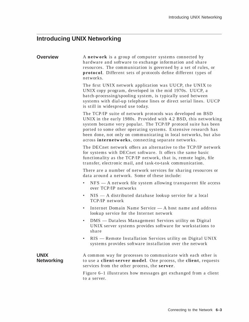
Introducing UNIX Networking
Introducing UNIX Networking
Overview A network is a group of computer systems connected byhardware and software to exchange information and shareresources. The communication is governed by a set of rules, orprotocol. Different sets of protocols define different types ofnetworks.
The first UNIX network application was UUCP, the UNIX toUNIX copy program, developed in the mid 1970s. UUCP, abatch-processing/spooling system, is typically used betweensystems with dial-up telephone lines or direct serial lines. UUCPis still in widespread use today.
The TCP/IP suite of network protocols was developed on BSDUNIX in the early 1980s. Provided with 4.2 BSD, this networkingsystem became very popular. The TCP/IP protocol suite has beenported to some other operating systems. Extensive research hasbeen done, not only on communicating in local networks, but alsoacross internetworks, connecting separate networks.
The DECnet network offers an alternative to the TCP/IP networkfor systems with DECnet software. It offers the same basicfunctionality as the TCP/IP network, that is, remote login, filetransfer, electronic mail, and task-to-task communication.
There are a number of network services for sharing resources ordata around a network. Some of these include:
• NFS — A network file system allowing transparent file accessover TCP/IP networks
• NIS — A distributed database lookup service for a localTCP/IP network
• Internet Domain Name Service — A host name and addresslookup service for the Internet network
• DMS — Dataless Management Services utility on DigitalUNIX server systems provides software for workstations toshare
• RIS — Remote Installation Services utility on Digital UNIXsystems provides software installation over the network
UNIXNetworking
A common way for processes to communicate with each other isto use a client-server model. One process, the client, requestsservices from the other process, the server.
Figure 6–1 illustrates how messages get exchanged from a clientto a server.
Connecting to the Network 6–3
Introducing UNIX Networking
Figure 6–1 Exchanging a Message on a UNIX Network
ClientProgram
ServerProgram
Message
Protocol
ZKOX−055000098−02−RGS
Host Host
Network
Each computer system on the network is called a host. Everyhost has a unique name and network address. Each host has aninterface, or controller, connecting it to the network.
There are two types of communication:
• Connection-oriented—Uses virtual circuits for transmission.Virtual circuits provide an apparent direct communication linebetween two processes. Connection-oriented services includeautomatic sequencing, error control, and flow control.
• Connectionless—Uses datagrams for transmission. Eachdatagram is an independent message. Connectionless serviceis transaction-oriented, and delivery and duplication protectionare not usually guaranteed.
For two processes to communicate there have to be rules coveringhow processes are supposed to interact, to send messages to eachother. A protocol is a set of rules defining how data is sent overa network.
Some of the tasks performed by protocols:
• Error detection—implemented by checksums, sequencenumbers, acknowledgments, and timers
• Error elimination (reliability)—implemented by retransmissionof packets or correction methods, for example, Hamming code
• Flow control—implemented by receive windows,acknowledgments
• Addressing—implemented by address fields, passed with thedata
Popular technologies for connecting computers include Ethernet,token ring, and Fiber Distributed Data Interface (FDDI).
6–4 Connecting to the Network

Introducing Internet Gateways
Introducing Internet Gateways
GatewayConnectsNetworks
Two distinct networks are connected by a gateway that isattached to both networks. The gateway passes information fromone network to the other.
The gateway may be a simple device to copy data from one sideto the other, such as a repeater or bridge. A repeater is ahardware device that connects Ethernet cable sections to extendthe local area network. It passes all data packets to the otherside. A bridge is a device that connects Ethernet cable sectionsto extend the local area network. It scans each data packet to seeif it should be forwarded to the other side. Bridges and repeatersextend a local network, rather than connecting separate networks.A bridge is an intelligent repeater; a bridge can decide whether topass packets to the other side.
The gateway may be more sophisticated and examine the datato decide if it should be forwarded, such as a router. A routerconnects two logical networks; a router can decide how to passpackets to a nonadjacent network. A router is what we usuallymean by a gateway on a UNIX network. Note that if a computersystem is a gateway, it must have more than one networkinterface.
The gateway may perform data format conversions if the twonetworks it connects use different protocols.
The figure shows host 3 as a gateway connecting two networks.
Figure 6–2 Gateway Connecting Two Networks
Host 1 Host 2
Host 4
Host 3
Host 5
Network 1
Network 2
Gateway
ZKOX−060000065−04−RGS
Connecting to the Network 6–5

Using Internet Addressing
Using Internet Addressing
Overview Every network interface must have a unique address. For oneprocess to contact another, it must know, or be able to find out,the other’s address.
There are several layers of addresses.
Lower layer protocols may use an address. For example, Ethernetuses a 48-bit address fixed in the hardware of each networkinterface. The IEEE assigns ranges of numbers to manufacturersof Ethernet controllers to control the uniqueness of the addresses.The IP protocol layer uses ARP to convert an Internet address toan Ethernet address.
InternetAddresses
The IP protocol defines a 32-bit address. This is normally writtenas four numbers separated by periods, with each representing 8bits of the address, for example, 128.30.0.99.
The address is divided logically in two parts, as shown in thefollowing table.
Table 6–1 Parts of an Internet Address
Part Description
Networknumber
Must be the same for all hosts connected to thesame network. No two networks can have thesame number if they are connected in any way, forexample, by a gateway or cable.
Host number No two hosts on the same network can have thesame number.
Network numbers are assigned by the Network InformationCenter (NIC) to control uniqueness. Host numbers are assignedby the local network manager.
To contact the NIC:
• Toll-free telephone number in the US: (800) 235-3155
• Electronic mail: [email protected]
The designers of the Internet wanted to limit the length of theaddress while allowing a maximum number of users. Therefore,the address space is partitioned for different types of networks:
• Class A networks use the first 8 bits for the network numberand the remaining 24 bits for the host number. This allows afew networks with a lot of hosts.
• Class B networks use the first 16 bits for the network numberand the remaining 16 bits for the host number.
6–6 Connecting to the Network

Using Internet Addressing
• Class C networks use the first 24 bits for the network numberand the remaining 8 bits host number. This allows a lot ofnetworks with up to 254 hosts.
• Class D is a special set of addresses used for multicasting.
Host numbers of all zeros or all ones are reserved for broadcastaddresses.
The IP header will contain the source and destination Internetaddresses.
Very few networks are large enough to require Class A addresses.Digital Equipment Corp. has a Class A address, and usessubnetworks to manage groups of hosts.
InternetAddressClasses
The following figure shows the Internet address classes.
Figure 6–3 Internet Address Classes
Type X . X . X . X
Reserved
Class A
Reserved
Class D
Class B
Class C
0
1−126
127
128−191 . 1−254
192−223 . 1−254 . 1−254
224−239
Host
HostHost
Reserved 240−255
ZKOX−060000065−06−RGS
Network number 127 is reserved for the local loopback address.
Address 255.255.255.255 is a global broadcast address
SampleInternetAddresses
The following table shows some sample addresses.
Internet Address Class Network Number Host Number
16.126.16.250 A 16 126.16.250
130.180.23.45 B 130.180 23.45
195.100.78.50 C 195.100.78 50
Users prefer to use a host name, such as tinker, rather thanremember the Internet address. Each host on the network hasaccess to a hosts database to convert host names to Internetaddresses. It may be a file, such as /etc/hosts , or a name service,such as the Internet Domain Name Service.
Connecting to the Network 6–7
Using Internet Addressing
EthernetAddresses
An Ethernet address can be determined on a local networkby using the ARP protocol. This checks an internal table orbroadcasts the Internet address to the local network and waits forthe host with that address or a local ARP server to reply with theEthernet address.
6–8 Connecting to the Network

Using Subnetwork Addresses
Using Subnetwork Addresses
Overview Subnetworks allow you to divide a large network into smallerlogical groups.
Part of the host address is designated as the subnet number.Figure 6–4 shows how an address is divided up.
Figure 6–4 Subnet Address
Network Address Subnet Address Host Address
InternetNetwork address Internet Host Address
ZKOX−060000065−07−RGS
The subnet number is usually the first octet of the host number.
Class C networks do not usually use subnets; they have only 8bits for the host number.
Routing from outside your network does not change; you are stillviewed as one network. It is only within your network that yousee separate networks.
Subnetworks Figure 6–5 shows the Class B network 128.12 with two subnets.Note in the figure that Host 3 is a gateway; it has one interfaceon each subnetwork.
Connecting to the Network 6–9

Using Subnetwork Addresses
Figure 6–5 Subnetworks
Host 1 Host 2
Host 4
Host 3
Host 5
ZKOX−060000065−08−RGS
Subnet 128.12.5
Subnet 128.12.7
128.12.5.1
128.12.7.1
128.12.5.2 128.12.5.3
128.12.7.2 128.12.7.3
A netmask is used to indicate the network and subnetworkaddress parts of the Internet address. The netmask is 32 bits,the same as the Internet address. Each bit in the netmask witha value 1 indicates the corresponding bit in the Internet addressis part of the network or subnetwork address; each 0 bit indicatesthe corresponding bit in the address is part of the host number.
Address 128.12.5.2 with netmask 255.255.255.0 indicates hostnumber 2 has a Class B address and an 8-bit subnet.
BroadcastAddresses
The Internet Protocol broadcast address allows messages to besent to all hosts on the network at the same time. This is called abroadcast.
All hosts on a network must have the same broadcast address.
The default format for a broadcast address is network address (ornetwork and subnet address) followed by all bits set to one.
• A Class B network with an 8-bit subnet 128.12.7 would have abroadcast address 128.12.7.255
• A Class B network (without subnetworks) 128.12 would havea broadcast address 128.12.255.255
6–10 Connecting to the Network

Using Subnetwork Addresses
Figure 6–6 Broadcast Addresses
ZKOX−060000065−09−RGS
Network Address 1111 . . . 1111
Network Address Subnet Address 1111 . . . 1111
Broadcast to all Hosts on the Network
Broadcast to all Hosts on the Subnetwork
Some older versions of UNIX used a broadcast address of thenetwork address followed by all 0 bits.
Connecting to the Network 6–11

TCP/IP Files
TCP/IP Files
Overview The Internet, or TCP/IP network, is configured using a number offiles, as described in the table.
Table 6–2 TCP/IP Network Files
File Function
/etc/hosts Lists known hosts and their addresses.
/etc/hosts.equiv Lists trusted hosts for login purposes.(Optional)
/etc/hosts.lpd Lists trusted hosts for remote printer use.(Optional)
/etc/inetd.conf Lists Internet services managed by theinetd (8) daemon.
/etc/networks Lists network and subnetwork names.
/etc/protocols Lists known Internet protocols.
/etc/services Lists known Internet services and portnumbers.
There are also a number of daemons used in TCP/IP networking:
inetd Internet service daemon. When it receives a servicerequest, it invokes a process to service the request.
rwhod Daemon maintains the database used by rwho (1) andruptime (1). It periodically queries the state of thesystem and broadcasts it to other systems; it receivesstatus broadcasts and stores status in the /var/rwhodirectory.
routed Daemon manages network routing tables.
Hosts File The /etc/hosts file contains a list of the known hosts on thenetwork.
Each host is listed on a separate line with fields separated byblanks. The format is:
address hostname [ alias . . . ]
## Host Database#127.0.0.1 localhost128.12.5.2 tinker128.12.5.1 TAILOR tailor taylor128.12.5.3 SOLDIER soldier128.12.7.2 SPY007 spy
6–12 Connecting to the Network

TCP/IP Files
The host file allows the system to look up the Internet address,given a host name. The system administrator can edit this fileand add or remove entries to add or remove a host system on thenetwork.
A system on a busy network might have an /etc/hosts filehundreds of lines long. It is not practical to keep this type oflist up to date. Many systems now use the Internet DomainName Service (implemented by BIND), where a name serverdynamically provides the host name to address lookups.
The UNIX term host is equivalent to node in DECnet terminology.
Trusted HostsFile
The /etc/hosts.equiv file specifies which hosts are trusted onyour system. This is a systemwide file maintained by the rootuser.
This file:
• Has impact on only the local host.
• Allows a user from a remote system to:
Log in to the same account on your system without apassword (using rlogin )
Copy a file from your system (using rcp )
Execute a command on your system (using rsh )
Enter one system name and optional user names per line.
# Trusted hoststailor joe samspy
The ~/.rhosts file allows an individual user to specify which hostsand accounts are trusted on your system in his account.
This file:
• Can exist in each user’s home directory
• Allows a user from a remote system to:
Log in to the same account on your system without apassword (using rlogin )
Copy a file from your system (using rcp )
Execute a command on your system (using rsh )
The file format is:
hostname [ username ]
Connecting to the Network 6–13

TCP/IP Files
LineprinterDaemon File
The /etc/hosts.lpd file specifies which hosts may send print jobsto your local printers.
• Enter one system name per line.
# Remote printer accesstailor
• A line starting with an asterisk (*) allows print jobs from allhosts to be accepted.
• The rs symbol in the /etc/printcap file will restrict use of aprinter to users on the local system.The syntax ~/ file means the file is in a user’s home directory.
InternetDaemonConfigurationFile
The /etc/inetd.conf file specifies the network services theinetd (8) daemon manages.
# Internet server configuration database# Syntax: ServiceName SocketType ProtocolName Wait/NoWait UserName \# ServerPath ServerArgsftp stream tcp nowait root /usr/sbin/ftpd ftpdtelnet stream tcp nowait root /usr/sbin/telnetd telnetdshell stream tcp nowait root /usr/sbin/rshd rshdlogin stream tcp nowait root /usr/sbin/rlogind rlogindexec stream tcp nowait root /usr/sbin/rexecd rexecd#tftp dgram udp wait root /usr/sbin/tftpd tftpd /tmp
.
.
.
• inetd waits for service requests, then activates the appropriateprogram to provide the service.
• Modify this file to add a nonstandard service or remove aservice from the system.
• Begin a line with a number sign (#) to comment it out andremove the service. Remove the comment and restart inetd toenable a service.
In earlier versions of UNIX, each of these network services had adaemon running all the time, consuming a lot of system resources.The 4.3 BSD version of UNIX introduced a manager daemoninetd (8) to wait for service requests and start the appropriatedaemon.
The configuration file is installed properly when set up for thestandard network services. However, you may add user-writtenservices or remove a service from your system.
6–14 Connecting to the Network

TCP/IP Files
Networks File The /etc/networks file allows file hosts on the same network orsubnetwork to be referred to as a group.
• Enter each network on a single line with fields separated byblanks.
• Format is:
netname netnumber [ alias . . . ]
The first field is the network name.
The second field is the network number (just the networkpart of the Internet address).
Any remaining fields are aliases.
• Example
# Internet networks#loop 127 loopbackengineering 128.12.5 engaccounting 128.12.7 act
Some commands, such as route (8) will accept a network name asan argument.
The netstat (1) command can display network names defined in/etc/networks .
The /etc/networks file is installed with the loop network name.Other entries are optional.
Protocols File The /etc/protocols file lists the known Internet protocols andtheir numbers.
• List each protocol on a separate line along with its protocolnumber and any aliases.
# Internet (IP) protocols#ip 0 IP # internet protocol, pseudo protocol numbericmp 1 ICMP # internet control message protocolggp 3 GGP # gateway-gateway protocoltcp 6 TCP # transmission control protocolpup 12 PUP # PARC universal packet protocoludp 17 UDP # user datagram protocol
• Modify this file to add a protocol to the network.
The protocols file is installed properly when set up for standardprotocols.
If a programmer writes his or her own protocol, it should beadded to /etc/protocols for inetd to manage daemons using it.
Connecting to the Network 6–15
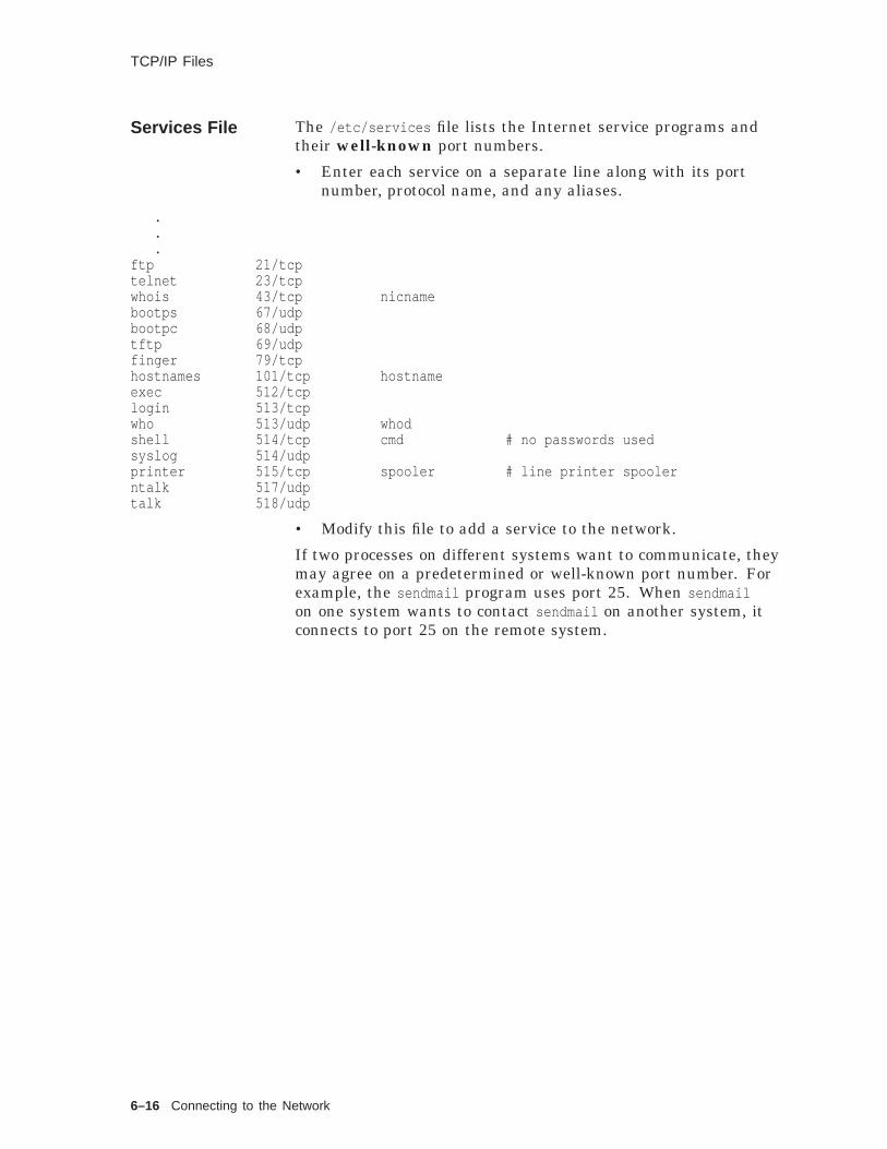
TCP/IP Files
Services File The /etc/services file lists the Internet service programs andtheir well-known port numbers.
• Enter each service on a separate line along with its portnumber, protocol name, and any aliases.
.
.
.ftp 21/tcptelnet 23/tcpwhois 43/tcp nicnamebootps 67/udpbootpc 68/udptftp 69/udpfinger 79/tcphostnames 101/tcp hostnameexec 512/tcplogin 513/tcpwho 513/udp whodshell 514/tcp cmd # no passwords usedsyslog 514/udpprinter 515/tcp spooler # line printer spoolerntalk 517/udptalk 518/udp
• Modify this file to add a service to the network.
If two processes on different systems want to communicate, theymay agree on a predetermined or well-known port number. Forexample, the sendmail program uses port 25. When sendmailon one system wants to contact sendmail on another system, itconnects to port 25 on the remote system.
6–16 Connecting to the Network

Setting Up and Managing a TCP/IP Network Using CDE
Setting Up and Managing a TCP/IP Network Using CDE
Overview The Network Configuration Manager or netconfig can be usedto configure network interfaces, enable and disable daemons,configure the system as an IP router, and modify and deleteentries in certain files.
• Use Network Configuration Manager to configure the followingnetwork interfaces:
Ethernet
FDDI
SLIP
Token Ring
• Enable or disable the following daemons:
gated
routed
rwhod
• Configure the system as an IP router
• Add, modify and delete entries in
/etc/routes
/etc/gateways
/etc/hosts
/etc/hosts.equiv
/etc/networks
StartingNetworkConfiguration
To start the Network Configuration application:
1. Click the Application Manager icon in the Front Panel.
2. Double-click the System_Admin icon.
3. Double-click the Configuration icon.
4. Double-click the Network icon.
In the first example, we will start the Network ConfigurationManager by double-clicking the Network Application icon in theConfiguration group shown in Figure 6–7.
Connecting to the Network 6–17

Setting Up and Managing a TCP/IP Network Using CDE
Figure 6–7 Invoking the Network Configuration Manager
SDI3-1A
Configuring anInterface
To configure an interface, in the Network Configuration mainwindow, select the interface from the Available NetworkComponents list box.
To modify an interface, select the interface from the ConfiguredNetwork Components list box.
In this example, we will modify the Ethernet interface.
1. We select Ethernet Interface-ln0 under Configured NetworkComponents, then click Modify Configuration...
6–18 Connecting to the Network

Setting Up and Managing a TCP/IP Network Using CDE
Figure 6–8 Network Configuration
SDI3-1B
2. The Configuring Ethernet Interface dialog box is displayed.
• The interface status in the example indicates that theprimary Ethernet is UP.
• The Interface Configuration indicates whether or not theinterface will be started on the next configuration reboot.
• The host name specifies the name for the interface whichin the example is vrroom.
• The IP address in the example is user supplied andthe network mask in the example is a class C mask255.255.255.0.
Connecting to the Network 6–19
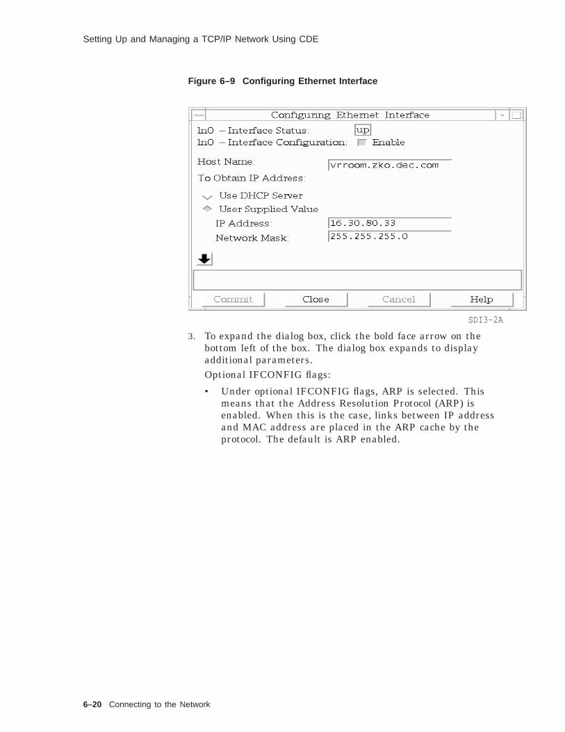
Setting Up and Managing a TCP/IP Network Using CDE
Figure 6–9 Configuring Ethernet Interface
SDI3-2A
3. To expand the dialog box, click the bold face arrow on thebottom left of the box. The dialog box expands to displayadditional parameters.Optional IFCONFIG flags:
• Under optional IFCONFIG flags, ARP is selected. Thismeans that the Address Resolution Protocol (ARP) isenabled. When this is the case, links between IP addressand MAC address are placed in the ARP cache by theprotocol. The default is ARP enabled.
6–20 Connecting to the Network

Setting Up and Managing a TCP/IP Network Using CDE
Figure 6–10 Optional IFCONFIG Flags
SDI3-2B
• Promiscuous directs the interface to receive all packetsrather than just those directed to the host. This feature isnormally disabled.
• The multicast feature allows the detection of multicastMAC packets such as ones with the LSB of the first byteequal to 1. Note, a broadcast address is one with all MACbits equal to 1. In special cases, special debug drivercode can be used. If this is the case, the Debug button isselected.
• Under optional IFCONFIG arguments in the example isthe standard MTU size for Ethernet of 1500 bytes (octets).
• Hop count is zero since the Ethernet card is zero hops fromanybody (if RIP happens to be on).
4. Click Commit to save any changes, then click Close after thechanges have been committed.
Adding orModifyingInformation in/etc/hosts
You can view and change entries in the /etc/hosts file throughthis application.
1. In the Network Configuration main window, click Host Filefrom the Configured Network Components list box.
Connecting to the Network 6–21

Setting Up and Managing a TCP/IP Network Using CDE
Figure 6–11 Host File
SDI3-3A
2. Click Modify Configuration. The Hosts dialog box is displayed.In the example, the contents of the /etc/hosts file is displayedin the text window. Five entries are displayed.
3. To modify an existing entry, select the entry (as in theexample), and the details are loaded into the four fields: HostName, Host Address, Aliases, and Comment. Any of thesefields can be edited. The four fields can be cleared by clickingon the clear button. After making the desired changes, clickCommit and then Close.
6–22 Connecting to the Network

Setting Up and Managing a TCP/IP Network Using CDE
Figure 6–12 Hosts Dialog Box
SDI3-3C
Connecting to the Network 6–23

Summary
Summary
IntroducingUNIXNetworking
A network consists of two or more computer systems linkedtogether for the purpose of exchanging information and sharingresources.
Each computer system on the network is called a host. Every hosthas a unique name and address.
For two processes to communicate, they have to agree on aprotocol, a set of rules covering how processes are supposed tointeract, to send messages to each other.
IntroducingInternetGateways
Two distinct physical networks are connected by a gateway that isattached to both networks. The gateway passes information fromone network to the other.
Using InternetAddressing
Every network interface must have a unique address. For oneprocess to contact another, it must know, or be able to find out theother’s address.
The IP protocol defines a 32-bit address, normally written as fournumbers separated by periods, with each representing 8 bits ofthe address, for example, 128.30.0.99.
The Internet address is logically divided in two parts: networknumber and host number. There are different classes ofaddresses, depending on the length of the parts.
Each host on the network has access to a hosts database toconvert host names to Internet addresses.
UsingSubnetworkAddresses
Subnetworks allow you to divide a large network into smallerlogical groups.
• Part of the host address is designated as the subnet number.
• A netmask is used to indicate the network and subnetworkaddress parts of the Internet address.
The Internet Protocol broadcast address allows messages to besent to all hosts on the network at the same time.
6–24 Connecting to the Network
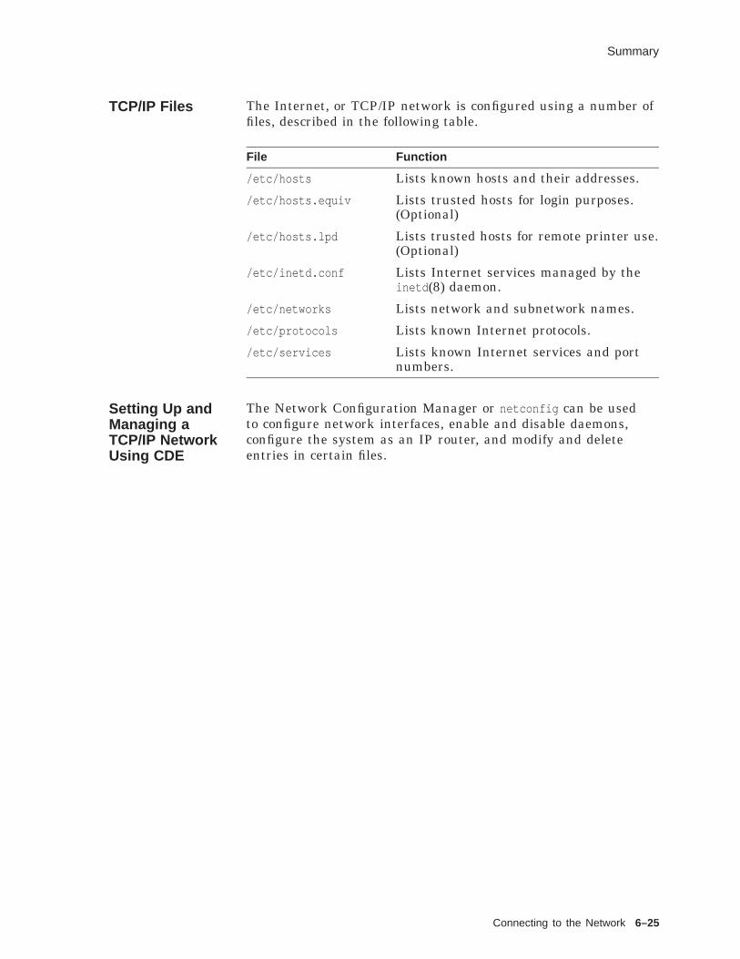
Summary
TCP/IP Files The Internet, or TCP/IP network is configured using a number offiles, described in the following table.
File Function
/etc/hosts Lists known hosts and their addresses.
/etc/hosts.equiv Lists trusted hosts for login purposes.(Optional)
/etc/hosts.lpd Lists trusted hosts for remote printer use.(Optional)
/etc/inetd.conf Lists Internet services managed by theinetd (8) daemon.
/etc/networks Lists network and subnetwork names.
/etc/protocols Lists known Internet protocols.
/etc/services Lists known Internet services and portnumbers.
Setting Up andManaging aTCP/IP NetworkUsing CDE
The Network Configuration Manager or netconfig can be usedto configure network interfaces, enable and disable daemons,configure the system as an IP router, and modify and deleteentries in certain files.
Connecting to the Network 6–25

Exercises
Exercises
Internet Files 1. Display each of the following files on your system.
a. /etc/hosts
b. /etc/hosts.equiv
c. /etc/inetd.conf
d. /etc/networks
e. /etc/protocols
f. /etc/services
2. Check the Reference Pages for more information on each ofthese files.
Setting Up andManaging aTCP/IP NetworkUsing CDE
1. Use the Network Configuration Manager to configure yournetwork interface. You must get your system IP address fromyour instructor or system administrator.
2. Use the Network Configuration Manager to add an entry tothe hosts files. You must get the name and address of anothersystem in the classroom or Lab area.
6–26 Connecting to the Network
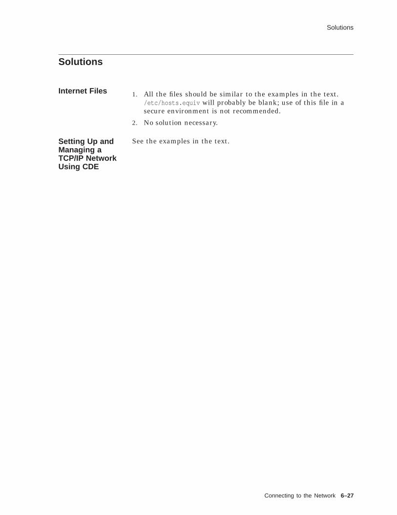
Solutions
Solutions
Internet Files 1. All the files should be similar to the examples in the text./etc/hosts.equiv will probably be blank; use of this file in asecure environment is not recommended.
2. No solution necessary.
Setting Up andManaging aTCP/IP NetworkUsing CDE
See the examples in the text.
Connecting to the Network 6–27


7Loading and Licensing Software
Loading and Licensing Software 7–1

About This Chapter
About This Chapter
Introduction Some system and optional software is organized into softwaresubsets, collections of executable and data files needed to performa specific function or provide a particular class of services.
Digital UNIX systems provide the setld (8) utility to manage thesesubsets:
• Load subsets onto the system
• Delete subsets from the system
• Inventory the subsets
• Verify the integrity of the subsets
• Configure subsets with node-specific information
Many software packages including the operating system arelicensed. Digital uses the License Management Facility and thenew CDE License Manager to manage software licenses online.
This chapter demonstrates the Digital UNIX software loadingutility setld to view the software subset inventory and load andunload software subsets. It also overviews the Digital LicenseManagement Facility (lmf ) utility and the CDE License Manager.Lab exercises provide practice with setld options and the CDELicense Manager.
Objectives To install optional software on a Digital UNIX system, you shouldbe able to:
• Add and remove software subsets
• Use the License Management Facility to manage onlinelicenses
• Describe the CDE environment
Resources • Digital UNIX Installation Guide, Chapter 8 shows the optionsto the setld command.
• Digital UNIX Software License Management
• Digital UNIX System Administration
7–2 Loading and Licensing Software

Loading and Unloading Software Subsets
Loading and Unloading Software Subsets
Preparing toLoad Software
Digital UNIX software is organized into subsets.
Use the setld (8) command to load and manage software subsetsfrom a distribution media after installation.
Before loading subsets, you may wish to check for sufficient diskspace:
• Use df to determine disk space.
• Consult the Release Notes for subset sizes and file systemsaffected.
Note
setld will automatically check that there is adequate filespace for the subset(s) requested to be installed.
Using the setldCommand
The format for the setld command is:
/usr/sbin/setld [-D dir ] - option [ location ][ subset ...]
• dir is an optional path specifying the destination.
• option includes:
l loads subset from distribution on location and updatesthe internal inventory.
d deletes subset from the system and updates the internalinventory.
i gives an inventory of all subsets known to the system, orall files for subset .
c configures subset by passing a message to the subsetcontrol program.
x extracts subset from distribution on dev into currentworking directory or dir (does not update internalinventory).
v verifies subset by checking its existence and by runningits installation verification procedure.
Except for the -i option, you must be superuser to runsetld .
• location specifies the distribution location. location can be:
A device special file name: /dev/rz4c —CD–ROM
The name of a directory: /mnt/ALPHA — disk distributiondirectory
Loading and Licensing Software 7–3

Loading and Unloading Software Subsets
The name of a remote installation server: tinker: —remote host
• subset specifies the name of the subset (see the Release Notes.)
To load software from a CD–ROM disk, mount the disk at aconvenient mount point and specify that mount point as thelocation for example:
# mount -r /dev/rz4c /mnt
# setld -l /mnt/ALPHA
The setld utility should not load or extract software if it wouldcause the percentage of free space on the file system to fall below10 percent (or minfree ).
DisplayingSoftwareSubsets
Use the setld -i command to display an inventory of softwaresubsets. This shows the status of each subset (installed, notinstalled, and so forth).
The status of a subset is determined by the existence of a lockfile or by the condition of its installation control file. If one ofthese two files does not exist, or if the control file is incomplete,the subset is considered to be incorrectly installed. Lock file,control file and inventory file for each subset are located in the/usr/.smdb. directory.
The inventory (-i ) option has two variations:
• List software subsets and their status
setld -i
Status field may be:
* blank - if the subset is not installed
* installed - if the subset is installed
* corrupt - if the subset failed to install correctly
* incomplete - if information in the subset control file isnot complete
• List files included in a particular subset
setld -i subset
SoftwareSubset DisplayExamples
Example 7–1 shows how to display software subsets with andwithout specifying a software subset name. When you invokesetld without a subset name, it lists all available subsets andidentifies which ones are currently installed. When you specify asubset name, setld lists all of the files for that subset.
7–4 Loading and Licensing Software

Loading and Unloading Software Subsets
Example 7–1 Listing Software Subsets with setld
$ /usr/sbin/setld -i
Subset Status Description------ ------ -----------BRXCKIT320 NetWorker Digital Client KitBRXSMAN320 NetWorker Server Reference PagesBRXSOAKIT320 installed NetWorker Server for Digital UNIXDIABASE210 installed DECevent Base kit (Translation / Analysis)EDXAXP200 installed Edex Alpha AXP Digital UNIX OutpostEDXHQ200 installed Edex Alpha AXP Digital UNIX HeadquartersEDXMAN200 installed Edex man pagesOSFACCT400 System Accounting Utilities (System Administration)OSFADVFS400 POLYCTR advfs (System Administration)OSFADVFSBIN400 POLYCTR advfs Kernel Modules (Kernel Build Environment)
.
.
.OSFXEXAMPLES400 X Window and X/Motif Programming Examples(Software Development)OSFXINCLUDE400 X Window and X/Motif Header Files (Software Development)OSFXLIBA400 X Window and X/Motif Static Libraries(Software Development)OSFXMAIL400 DECwindows Mail Interface (Mail Applications)OSFXMIT400 Additional X Applications (Windows Applications)OSFXNEST400 Nested X Server (Windows Applications)OSFXOEM400 X Customizations for OEM (Windowing Environment)OSFXPRINT400 installed Graphical Print Configuration Application(System Administration)OSFXSYSMAN400 installed Graphical Base System Management Utilities(System Administration)OSFXVFB400 Virtual X Frame Buffer (Windows Applications)
$ /usr/sbin/setld -i OSFPRINT400
./etc/.new..lprsetup.dat
./sbin/init.d/lpd
./sbin/rc0.d/K05lpd
./sbin/rc2.d/K00lpd
./sbin/rc3.d/S65lpd
./usr/bin/cancel
./usr/bin/lp
./usr/bin/lpq
./usr/bin/lpr
./usr/bin/lprm
./usr/bin/lpstat
./usr/lbin/ansi_2of...
./usr/lbin/vpsf
./usr/lbin/vsort
./usr/lbin/xf
./usr/lib/nls/msg/en_US.ISO8859-1/lprsetup.cat
./usr/lib/nls/msg/en_US.ISO8859-1/printer.cat
./usr/sbin/lpc
./usr/sbin/lprsetup
./usr/sbin/lptest
./usr/var/spool/lpd
LoadingSoftwareSubsets
Use the setld -l command to load a software subset.
The following table shows some of the possible source anddestination combinations.
Loading and Licensing Software 7–5
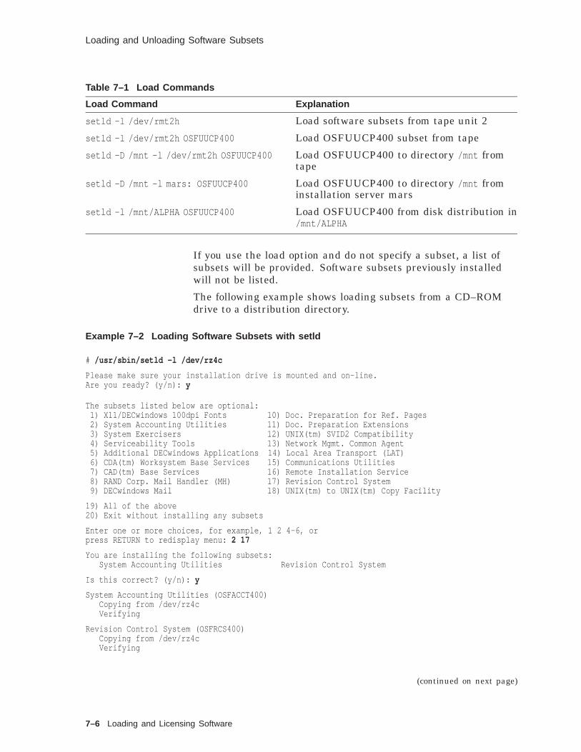
Loading and Unloading Software Subsets
Table 7–1 Load Commands
Load Command Explanation
setld -l /dev/rmt2h Load software subsets from tape unit 2
setld -l /dev/rmt2h OSFUUCP400 Load OSFUUCP400 subset from tape
setld -D /mnt -l /dev/rmt2h OSFUUCP400 Load OSFUUCP400 to directory /mnt fromtape
setld -D /mnt -l mars: OSFUUCP400 Load OSFUUCP400 to directory /mnt frominstallation server mars
setld -l /mnt/ALPHA OSFUUCP400 Load OSFUUCP400 from disk distribution in/mnt/ALPHA
If you use the load option and do not specify a subset, a list ofsubsets will be provided. Software subsets previously installedwill not be listed.
The following example shows loading subsets from a CD–ROMdrive to a distribution directory.
Example 7–2 Loading Software Subsets with setld
# /usr/sbin/setld -l /dev/rz4c
Please make sure your installation drive is mounted and on-line.Are you ready? (y/n): y
The subsets listed below are optional:1) X11/DECwindows 100dpi Fonts 10) Doc. Preparation for Ref. Pages2) System Accounting Utilities 11) Doc. Preparation Extensions3) System Exercisers 12) UNIX(tm) SVID2 Compatibility4) Serviceability Tools 13) Network Mgmt. Common Agent5) Additional DECwindows Applications 14) Local Area Transport (LAT)6) CDA(tm) Worksystem Base Services 15) Communications Utilities7) CAD(tm) Base Services 16) Remote Installation Service8) RAND Corp. Mail Handler (MH) 17) Revision Control System9) DECwindows Mail 18) UNIX(tm) to UNIX(tm) Copy Facility
19) All of the above20) Exit without installing any subsets
Enter one or more choices, for example, 1 2 4-6, orpress RETURN to redisplay menu: 2 17
You are installing the following subsets:System Accounting Utilities Revision Control System
Is this correct? (y/n): y
System Accounting Utilities (OSFACCT400)Copying from /dev/rz4cVerifying
Revision Control System (OSFRCS400)Copying from /dev/rz4cVerifying
(continued on next page)
7–6 Loading and Licensing Software

Loading and Unloading Software Subsets
Example 7–2 (Cont.) Loading Software Subsets with setld
## /usr/sbin/setld -D /usr/local -l /dev/rz4c OSFPRINT400
Please make sure your installation drive is mounted and on-line.Are you ready (y/n)? y
Printer Support Environment (OSFPRINT400)Copying from /dev/rz4cVerifying
#
Loading and Licensing Software 7–7

Loading and Unloading Software Subsets
Deleting aSoftwareSubset
Use the setld -d command to remove a software subset.
Do not remove software subsets by any command other thansetld because the system keeps a record of the software that isinstalled.
The setld utility checks and warns:
• If a subset has been marked during manufacture so it cannotbe deleted
• If a subset being deleted is required by other subsets installedon the system
Example 7–3 shows how to remove a software subset.
Example 7–3 Removing a Software Subset with setld
# /usr/sbin/setld -d OSFRCS400
Deleting Revision Control System (OSFRCS400).
# setld -d OSFBASE400setld: Sorry, You may not delete the Base System (OSFBASE400) subset
#
7–8 Loading and Licensing Software

Licensing Your Software
Licensing Your Software
Overview Digital UNIX systems use the Digital License ManagementFacility (LMF) to control access to software.
• Each licensed software package comes with a ProductAuthorization Key (PAK), a set of license information thatmay be hardcopy or an online file.
• The PAK is loaded into a system database.
• Software can query the database to see if it is licensed, or forhow much capacity.
One possible use of licensing is to allow vendors to provide a fullworking copy of software for a limited time demonstration. After60 days, the license can expire and the program will not run.
Types ofLicenses
There are several types of licenses:
• Availability or capacity licenses — Grants license unitsbased on the power of the hardware without restrictions forparticular processors.
Once a product has been licensed on a processor, usershave unlimited access to the product.
• Activity or per-user licenses — Restricts the number ofsimultaneous users of a product.
The number of licensed users can be increased bypurchasing additional license units.
The licenses for DEC OSF/1 Version 4.0 are:
• osf-usr A two-user license (basic license)
• osf-svr A license for a RIS server
• osf-dev A developer’s license (required to use dbx )dbx -k for kernel debugging does not require the developer’slicense; all other uses of dbx do.
A Sample PAK The following example shows a sample PAK for the RemoteInstallation Service.
Loading and Licensing Software 7–9

Licensing Your Software
Example 7–4 A Sample PAK
LICENSE PAK(PRODUCT AUTHORIZATION KEY)
*************************************************PAK ID:
Issuer: DEC 1Authorization Number: SQM021856 2
PRODUCT ID:Product Name: OSF-SVR 3
Producer: DEC 4
NUMBER OF UNITS:Number of units: 100 5
KEY LEVEL:Version: 1.0 6
Product Release Date: 1-MAR-1996 7
KEY TERMINATION DATE:Key Termination Date: 1-APR-1996 8
RATING:Availability Table Code: CONSTANT=100 9
Activity Table Code: 1 0
MISCELLANEOUS:Key Options: NO_SHARE 1 1
Product Token: 1 2
Hardware-Id: 1 3
Checksum: 1-POFE-IHOI-FHNH-KHDK 1 4
*************************************************
1 Issuer is the LMF name for the supplier of the PAK; usuallyDEC, may be DEC_EUROPE or other vendor
2 Authorization number uniquely identifies license
3 Product name is the LMF name for product - may be slightlydifferent than that in Software Product Description due toLMF internal restrictions
4 Producer is name of company producing the software product
5 Number of units is number of license units supplied with thisPAK; zero (0) means unlimited size (See also table code fields)
6 Version is software product version (optional); if present, LMFrestricts product use to versions up to and including thatversion
7 Product release date (optional); if present, LMF restrictsproduct use to versions released on or before that date
8 Key termination date (optional) is termination date of PAK.After this date the PAK is no longer valid. (Useful forproviding a demonstration version of product.)
9 Availability table code (for availability license) the number ofunits required to give unlimited use on a processor
7–10 Loading and Licensing Software
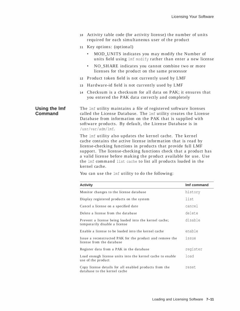
Licensing Your Software
1 0 Activity table code (for activity license) the number of unitsrequired for each simultaneous user of the product
1 1 Key options: (optional)
• MOD_UNITS indicates you may modify the Number ofunits field using lmf modify rather than enter a new license
• NO_SHARE indicates you cannot combine two or morelicenses for the product on the same processor
1 2 Product token field is not currently used by LMF
1 3 Hardware-id field is not currently used by LMF
1 4 Checksum is a checksum for all data on PAK; it ensures thatyou entered the PAK data correctly and completely
Using the lmfCommand
The lmf utility maintains a file of registered software licensescalled the License Database. The lmf utility creates the LicenseDatabase from information on the PAK that is supplied withsoftware products. By default, the License Database is in/usr/var/adm/lmf .
The lmf utility also updates the kernel cache. The kernelcache contains the active license information that is read bylicense-checking functions in products that provide full LMFsupport. The license-checking functions check that a product hasa valid license before making the product available for use. Usethe lmf command list cache to list all products loaded in thekernel cache.
You can use the lmf utility to do the following:
Activity lmf command
Monitor changes to the license database history
Display registered products on the system list
Cancel a license on a specified date cancel
Delete a license from the database delete
Prevent a license being loaded into the kernel cache;temporarily disable a license
disable
Enable a license to be loaded into the kernel cache enable
Issue a reconstructed PAK for the product and remove thelicense from the database
issue
Register data from a PAK in the database register
Load enough license units into the kernel cache to enableuse of the product
load
Copy license details for all enabled products from thedatabase to the kernel cache
reset
Loading and Licensing Software 7–11

Licensing Your Software
Activity lmf command
Unload enough license units from the kernel cache to reducethe use of the product by the number of users specified
unload
You can enter lmf commands on the command line.
# lmf register
Alternatively, you can enter the lmf utility and type thecommands after the prompt.
# lmflmf> register
You should register and load any license for your operatingsystem. For example:
# /usr/sbin/lmf register# /usr/sbin/lmf load 0 osf-svr
Using lmf toRegister aLicense
Use lmf register to edit an empty template and register thelicense details from the PAK. The editor used is defined by theEDITOR environment variable, or defaults to vi .
When you type in lmf register , the system invokes the editor anddisplays an empty template. You should use the editor commandsto type in the PAK data.
You can type the data in uppercase or lowercase letters; LMFconverts it to uppercase. Any fields which are blank on the PAKshould be left blank; any fields filled in on the PAK should betyped exactly as you see them. LMF may return a checksum errorif you omit or incorrectly enter any license data.
You can bypass the editor by registering a PAK from a file thatcontains valid license data by using the following command
# lmf register - < PAK_file
When you leave the editor, LMF scans the completed template tomake sure you entered the license data correctly.
If the license data is correct, LMF registers the license in thelicense database.
Using lmfsetupto Register aLicense
You can use the /usr/sbin/lmfsetup shell script to register datasupplied by a PAK.
• lmfsetup prompts you for the data associated with each fieldon a PAK.
• Once you enter all the data, LMF makes sure you havesupplied entries for all mandatory fields and that the value inthe Checksum field validates the license data.
If the data is correct, LMF registers the PAK in the licensedatabase.
7–12 Loading and Licensing Software

Licensing Your Software
If any data is incorrect, LMF displays the appropriateerror message and gives you an opportunity to reenter thedata.
Example 7–5 shows how to use the lmfsetup command.
Example 7–5 Using the lmfsetup Command
# lmfsetupRegister PAK (type q or quit to exit) [template] Return
Issuer : DECAuthorization Number : SQM021856
Product Name : OSF-SVRProducer : DEC
Number of units : 100Version : 1.0
Product Release Date : 1-MAR-1996Key Termination Date : 1-APR-1996
Availability Table Code : CONSTANT=100Activity Table Code :
Key Options : NO_SHAREProduct Token :
Hardware-Id :Checksum : 1-POFE-IHOI-FHNH-KHDK
Loading and Licensing Software 7–13

Using the CDE License Manager
Using the CDE License Manager
Overview Digital UNIX Version 4.0 workstations or graphic systems usethe CDE License Manager to control access to software. ThisCDE application presents a new user interface as part of theDailyAdmin tools for system administration. Note that the licensearchitecture and strategy remains consistent with that describedearlier for the lmf utility. The license actions with the CDELicense Manager are:
• File Open - to add a license from a file
• Edit New - to add a license with an editor
• Edit List - to list a specific license
• Edit Issue - to write a PAK to a file
• Edit Delete - to delete a license
Starting theCDE LicenseManager
As with the other system administration tools, the CDE LicenseManager is invoked through System_Management_Utilities. Thenext figure shows the CDE License Manager being selected fromthe DailyAdmin window.
Figure 7–1 CDE License Manager
Note that the system is protected from casual user input throughthe use of this Pop-up window which requires the root passwordto continue.
7–14 Loading and Licensing Software

Using the CDE License Manager
Using theLicenseManager
The License Manager window shows the current licenses loadedinto the system. This figure displays two licenses.
• OSF-BASE
• OSF-USR
Both are required for Digital UNIX Version 4.0. The baselicense grants the right to use the various services of the DigitalUNIX operating system on a single processor. This license alsoauthorizes two concurrent interactive users of the system. Theusr license allows multiple users on the system and requires thebase license. The actual number of users allowed is a functionalpiece of the license PAK as noted earlier.
The menu options for license operations are:
• File Open - to add a license from a file
• Edit New - to add a license with an editor
• Edit List - to list a specific license
• Edit Issue - to write a PAK to a file
• Edit Delete - to delete a license
Figure 7–2 Minimum Licenses
Note that the OSF-BASE license is highlighted, meaning that ithas been selected (MB1) by the user.
Loading and Licensing Software 7–15

Using the CDE License Manager
Using Edit List To view the details of a currently loaded license on the system:
1. Select Edit from the menu bar.
2. Choose List from the pull-down menu.
The List License window is displayed.
Figure 7–3 List a License
Using Edit New During the course of a system installation, the systemadministrator is required to enter a new license on the platform.From the License Manager window, select Edit and choose Newfrom the pull-down menu if you have a hardcopy of the licenseinformation and want to manually enter it into the system. TheNew License window is displayed and shown in the next figure.
7–16 Loading and Licensing Software

Using the CDE License Manager
Figure 7–4 Edit New Option
Enter the license details for the PAK using this window. Whenall information is complete, click OK to load the license into thelicense database. Alternately you could click Apply, which alsoloads the new license but does not exit the New License window,allowing you to enter another license after pressing the Clearbutton.
Using FileOpen
You can enter a new license from a file located on the systemrather than using the editing method. The default file location isshown in the next figure.
Loading and Licensing Software 7–17

Using the CDE License Manager
Figure 7–5 File Open option
Optionally you may select another folder which contains thelicense information as shown in the following figure.
7–18 Loading and Licensing Software

Using the CDE License Manager
Figure 7–6 PAK in User File
Loading and Licensing Software 7–19

Summary
Summary
Loading andUnloadingSoftwareSubsets
Digital UNIX software is organized into subsets. Use thesetld command to load and manage software subsets from adistribution media after installation.
setld -i Displays inventory of software subsets
setld -l Loads software subsets
setld -d Deletes software subsets
Licensing YourSoftware
Digital UNIX systems use the Digital License ManagementFacility (LMF) to control access to software.
• Each licensed software package comes with a ProductAuthorization Key (PAK), a set of license information whichmay be on paper or an online file.
• The PAK is loaded into a system database.
• You can use the /usr/sbin/lmf utility to register a license andmanage the license database.
• You can use the /usr/sbin/lmfsetup shell script to register alicense.
Using theCDE LicenseManager
You can use the CDE License Manager to administer licenses.
Table 7–2 CDE License Manager VS LMF Commands
CDE License Manager LMF
Edit List list
Edit Delete delete
Edit Issue issue
Edit New register
Edit New lmfsetup
File Open register - < file
7–20 Loading and Licensing Software

Exercises
Exercises
Instructor Note
The following exercises are designed to be bothinstructional and practical in that they support other labexercises to follow. Give priority to the CDE licensingexercise over the LMF setup exercise.
• Licensing - each platform must have at a minimum abase and a usr license. Have these available for thestudent team on each platform.
a. OSF-BASE on hardcopy - students use EDIT NEWoption
b. OSF_USR in a file - students use FILE OPEN
• SW loading notes
a. DECevent is used in Chapter 13 (DIABASE210)
b. NetWorker Save and Restore in Chapter 10(BRXCKIT320, BRXMAN320, BRXSOAKIT320)
c. DEC_Fortran_RTL (DFARTL364) is used only topractice deleting a subset loaded in error
*** The installation guide incorrectly lists some of thesoftware subsets.If CD–ROMs are not available in the classroom, andsubsets are available on a RIS server, students will have toset up the network.Also, the RIS server needs to have the appropriate subsetsloaded.
LoadingSoftwareSubsets
1. Determine the subsets required for these applications.
DEC_EVENT
NetWorker_SingleServer
DEC_Fortran_RTL
2. Display the inventory of software subsets.
3. Load the subsets required for class exercises.
CheckingSoftwareSubsets
1. Determine if the Printer Support Environment subset isloaded.
2. List the contents of the Printer Support Environment subset.
Loading and Licensing Software 7–21

Exercises
DeletingSoftwareSubsets
Oops ... we really do not need the DEC Fortran subset. Delete itfrom the system.
Licensing YourSoftware
1. Use the lmf list command to display registered products.
2. Use lmf register and enter the fields from the sample PAKin the text. When you leave the editor, the checksum will notvalidate (this is not a valid PAK). Abort the operation.
3. Use lmfsetup to enter the PAK data. If your instructor has avalid PAK, use that data.
Using CDELicenseManager
1. Check the system for existing licenses.
2. Enter the OSF-BASE license and the OSF-USR license.
7–22 Loading and Licensing Software

Solutions
Solutions
LoadingSoftwareSubsets
1. Consult the Installation Guide, Appendix C and record thesubset names below.
DEC_EVENT _______________________________
NetWorker_SingleServer _______________________________
DEC_Fortran_RTL _______________________________
2. Display the inventory of software subsets.
# /usr/sbin/setld -i
3. Load the subsets required for class exercises.
# /usr/sbin/setld -l DIABASE210
# /usr/sbin/setld -l BRXCKIT320 BRXMAN320 BRXSOAKIT320
# /usr/sbin/setld -l DFARTL364
CheckingSoftwareSubsets
1. Determine if the Printer Support Environment subset isloaded.
# setld -i | grep rint
OSFPRINT400 Printer Support Environment
2. List the contents of the Printer Support Environment subset.
# setld -i OSFPRINT400./sbin/init.d/lpd./sbin/rc0.d/K05lpd./sbin/rc2.d/K00lpd./sbin/rc3.d/S65lpd./usr/bin/lp./usr/bin/lpq./usr/bin/lpr./usr/bin/lprm./usr/bin/lpstat...
DeletingSoftwareSubsets
# /usr/sbin/setld -d DFARTL364
Loading and Licensing Software 7–23
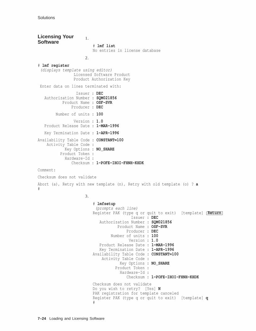
Solutions
Licensing YourSoftware
1.
# lmf listNo entries in license database
2.
# lmf register(displays template using editor)
Licensed Software ProductProduct Authorization Key
Enter data on lines terminated with:
Issuer : DECAuthorization Number : SQM021856
Product Name : OSF-SVRProducer : DEC
Number of units : 100
Version : 1.0Product Release Date : 1-MAR-1996
Key Termination Date : 1-APR-1996
Availability Table Code : CONSTANT=100Activity Table Code :
Key Options : NO_SHAREProduct Token :
Hardware-Id :Checksum : 1-POFE-IHOI-FHNH-KHDK
Comment:
Checksum does not validate
Abort (a), Retry with new template (n), Retry with old template (o) ? a#
3.
# lmfsetup(prompts each line)
Register PAK (type q or quit to exit) [template] ReturnIssuer : DEC
Authorization Number : SQM021856Product Name : OSF-SVR
Producer : DECNumber of units : 100
Version : 1.0Product Release Date : 1-MAR-1996Key Termination Date : 1-APR-1996
Availability Table Code : CONSTANT=100Activity Table Code :
Key Options : NO_SHAREProduct Token :
Hardware-Id :Checksum : 1-POFE-IHOI-FHNH-KHDK
Checksum does not validateDo you wish to retry? [Yes] NPAK registration for template canceledRegister PAK (type q or quit to exit) [template] q#
7–24 Loading and Licensing Software

Solutions
Using CDELicenseManager
1. Select the CDE License Manager from the DailyAdminwindow. In the CDE License Manager window, select Edit andchoose List from the pull-down menu.
No entries in license database
2. Select the CDE License Manager from the DailyAdminwindow. In the CDE License Manager window, select Edit andchoose New from the pull-down menu.
using the license PAK information supplied by your instructor
Loading and Licensing Software 7–25


8Configuring the Kernel
Configuring the Kernel 8–1
About This Chapter
About This Chapter
Introduction The kernel is the central program that manages the computersystem. It controls system scheduling, memory management,input and output services, device management, and organizationof the file systems. The kernel is set up, or configured, and builtfor each system at every site.
The system configuration file allows the system administratorto specify the devices and some system parameters that definethe system. The configuration software uses this file to build thekernel. Performing a system installation builds a static kernelconfigured for that system.
Digital UNIX 4.0 systems provide the capability to configure thesystem statically (as in past system releases) or use the newdynamic technique.
In a static configuration, you edit a configuration file, searchbuild a new kernel, and reboot the system.
Dynamic configuration allows you to configure and loadkernel subsystems without rebooting. You update the subsystemconfiguration database and the kernel will automatically configurethe subsystem.
Dynamic configuration is available only for drivers andsubsystems that are set up to be dynamically loadable. You canuse dynamic configuration to change certain system parameters,for example.
Objectives To configure the kernel for a Digital UNIX system, you should beable to:
• Identify when to build a new kernel
• Describe the system configuration file
• Use doconfig to build a kernel automatically
• Dynamically configure a kernel with sysconfig and sysconfigdb
• Reconfigure kernel attributes
Resources • System Tuning and Performance Management
• Digital UNIX System Administration, Chapters 4 and 5
• Nemeth, Snyder, & Seebass, UNIX System AdministrationHandbook, Chapter 8 describes BSD configuration file andbuilding a kernel
8–2 Configuring the Kernel
Building a New Kernel
Building a New Kernel
Overview You may need to build a new kernel to:
• Add a new device and its static driver to your configuration
• Remove a device and its static driver from your configuration
• Tune the operating system
• Add layered products
You can configure a kernel:
• Automatically with doconfig (8) for a static kernel
• Dynamically modify kernel attributes and subsets withsysconfig and sysconfigdb
With either method, the system configuration file is modified andkernel is reconfigured.
Some drivers can be dynamically loaded. To add one of these,you do not have to change the configuration file and rebuild thekernel.
If you remove a device and its driver from your configuration, itis not necessary to change the configuration file and rebuild thekernel, but doing so will reduce the size of the kernel.
An example of a system tuning operation is changing from oneswap area to two separate swap areas on two disks, to improveperformance. (This can be done using the /etc/fstab file, ratherthan building a new kernel.) Another example of system tuning isincreasing the percentage of memory allocated to the I/O buffercache.
Some layered products require building a new kernel; some donot. For example, Pathworks and LSM require changing systemparameters and building a new kernel.
A kernel can be modified using the sysconfig command toload/unload dynamic subsystems; as well as change systemattributes.
You must be logged in as root to perform either procedure.Building a kernel using doconfig -c can be done in multiusermode. But you must shut down and reboot the new kernel for thechanges to take effect.
Configuring the Kernel 8–3

System Configuration File
System Configuration File
Overview The system configuration file is a text file. It can be modified byusing an editor, such as vi , or the new CDE Personal ApplicationsEditor. In general, this file does not need to be edited.
The configuration file defines extensions to the kernel. Filesystems, network protocol families, physical and pseudodevicedrivers, and STREAMS drivers and modules are supported assubsystems, or extensions.
If you have enough disk space, you can build more than onekernel, and boot selectively among them, to turn various devicesor features on or off.
Many of the parameters in /sys/conf/param.c have equivalentconfiguration file keywords which would override the default valuein param.c . Whenever possible, use /usr/bin/X11/dxkerneltuner toalter the value of tunable system parameters.
The system configuration file and other files used to build thekernel are located in subdirectories of /sys :
/usr/sys/conf/ NAME The system configuration file.(NAME is the system namein uppercase letters.)
/usr/sys/conf/GENERIC A generic configuration fileused as a template; containsall possible software andhardware options.
/usr/sys/conf/param.c Contains default valuesfor a number of systemparameters.
/usr/sys/conf/files List of common files used tobuild the system.
/usr/sys/conf/files. NAME List of files specific to thissystem.
The system configuration file uses a number of keywordsdescribed in the following sections. See Digital UNIX SystemAdministration, Chapter 4, for a list of configuration keywordsand their values.
System Administration also describes an extension for statickernel configuration for layered products, using the /sys/conf/ NAME.list and config.file files.
The next several pages describe entries in the systemconfiguration file.
8–4 Configuring the Kernel

System Configuration File
GlobalKeywords
Global keyword values describe the system. The following tableprovides some examples.
Table 8–1 Global Keywords
Keyword Function Example
ident Identifies the kernel; generally thesystem name in uppercase letters
ident TINKER
maxdsiz Defines the maximum process datasegment size
maxdsiz 33554432
maxssiz Defines the maximum process stacksize
maxssiz 33554432
maxusers Sizes several system data structures,including the system process table
maxusers 32
maxthreads Defines the maximum number ofthreads per task
maxthreads 256
bufcache Defines the percentage of physicalmemory allocated for I/O buffer cache
bufcache 20
cpu Defines the specific architecturalmachine type
cpu "DEC3000_500"
Guidelines for setting maxusers:
System DescriptionmaxusersValue
Limited memory and a small number of users 8 or 16
Moderate hardware and moderate number of users 32
Large system with heavy work load 64
If you are not sure 32
Default 32
ChangingParameters forPerformance
Changing any of the tunable parameters has tradeoffs; you gainin one area and lose in another.
Use the maxusers parameter to restrict system usage. It controlsthe sizes of several important system resources including the totalnumber of files and processes that can be open/active at any onetime. This indirectly controls the number of simultaneous usersthe system can support providing no license restrictions apply.
You can increase the number of entries in the block and characterdevice switch tables to accommodate loadable drivers. If youreceive a message from the config command or from the loadabledriver configuration manager cfgmgr indicating a table is toosmall, edit the configuration file and specify values for the optionsMAX_BDEVSWor MAX_CDEVSW. For example:
Configuring the Kernel 8–5

System Configuration File
options MAX_BDEVSW=80options MAX_CDEVSW=130
SystemDefinitionKeyword
The system definition identifies the name of the kernel, thelocation of the root file system and dump and swap areas. It usesthe keyword configuration.
The recommended configuration entry is as follows:
config vmunix swap generic
This selects the a partition of the disk from which the kernelwas booted as the root file system and the swap areas from the/etc/fstab file. The crash dump area is the same as the firstswap area.
You can also specify the disk and partition for the root file systemand the swap and dump areas.
config vmunix root on rz4a swap on rz1b and rz2b dumps on rz1b
OptionsKeywordDefinitions
Options keyword definitions specify software to be compiled intothe system, including subsystems and additional functionality.Many are mandatory, not optional.
Some examples of options definitions:
options Machoptions OSFoptions CDFSoptions NFSoptions UFSoptions RT
MakeoptionsKeywordDefinitions
Makeoptions keyword definitions are passed to the compiler,assembler, and linker when building the kernel.
This example turns on debugging:
makeoptions CDEBUGOPTS="-g3"
PseudodeviceKeywordDefinitions
Pseudodevice definitions identify pseudodevice drivers forterminal services, the Logical Storage Manager, network services,and so forth.
Some examples of pseudodevice definitions:
pseudo-device rptypseudo-device xconspseudo-device etherpseudo-device lsm1
Pseudodevice definitions identify components for which there isno associated hardware; for example, a pseudoterminal.
Pseudoterminals are used for incoming network logins and forinteractive windows. The pty entry defines the maximum numberof pseudoterminals; it can be any value less than or equal to 3162.For example:
8–6 Configuring the Kernel

System Configuration File
pseudo-device rpty
For pseudoterminals, the system configuration file can includeeither options RPTY , or pseudo-device pty or pseudo-device rpty ,but not both.
Configuring the Kernel 8–7

System Configuration File
Example 8–1 Alpha AXP System Configuration File
ident "GERTIE"
options UERFoptions OSFoptions _LMF_options BIN_COMPAToptions COMPAT_43options MACHoptions MACH_IPC_TCACHEoptions MACH_IPC_WWAoptions MACH_IPC_XXXHACKoptions BUFCACHE_STATSoptions INOCACHE_STATSoptions STAT_TIME...
## Standard options.#options UNIX_LOCKSoptions SER_COMPAToptions RT_PREEMPToptions RT_SCHEDoptions RT_SCHED_RQoptions RT_PMLoptions RT_TIMERoptions RT_SEMoptions RT_SEMoptions RT_IPC#makeoptions CDEBUGOPTS="-g3"makeoptions COMPRESS="-compress"makeoptions PROFOPTS="-DPROFILING -DPROFTYPE=4"
## Max number of processors in the system (DO NOT CHANGE)#processors 16
## Special options (see configuring the kernel chapter# in the Guide to System Administration)#dfldsiz 134217728maxdsiz 1073741824dfldsiz 2097152maxssiz 33554432cpu "DEC3000_500"maxusers 32config vmunix swap generic
(continued on next page)
8–8 Configuring the Kernel

System Configuration File
Example 8–1 (Cont.) Alpha AXP System Configuration File
bus tc0 at nexus?callout after_c "../bin/mkdata tc"bus tcds0 at tc0 slot 6 vector tcdsintrcontroller scsi0 at tcds0 slot 0controller scsi1 at tcds0 slot 1bus tcds1 at tc0 slot 1 vector tcdsintrcontroller scsi2 at tcds1 slot 0controller scsi3 at tcds1 slot 1bus tza0 at tc0 slot 4 vector tzaintrcontroller scsi4 at tza0 slot 0controller scc0 at tc0 slot 7 vector sccintrcontroller fb0 at tc0 slot 8 vector faintcontroller bba0 at tc0 slot 7 vector bantercontroller ln0 at tc0 slot 7
pseudo-device sysv_habpseudo-device svid_three_habpseudo-device svr_four_habpseudo-device soe_two_habpseudo-device rt_habpseudo-device etherpseudo-device looppseudo-device prf 6pseudo-device lv 2pseudo-device lsm_ted 0pseudo-device lsm 1pseudo-device ws
Configuring the Kernel 8–9

Building a Static Kernel
Building a Static Kernel
Overview The doconfig program creates a new (or modifies an existing)system configuration file, creates the special device files forstatically configured drivers, and builds a new Digital UNIXsystem kernel.
You need the following Digital UNIX software subsets installed torebuild your kernel:
• OSFBINnnn
• OSFBINCOMnnn
nnn corresponds to the operating system version.
Use setld -i to verify that these subsets are installed.
Using thedoconfigProgram
The following example shows how to automatically build akernel.
Example 8–2 Building a Kernel with the doconfig Program
1 $ su2 # cp /vmunix /vmunix.old3 # cp /genvmunix /vmunix4 # /usr/sbin/shutdown -r now Boot generic kernel
5 # /usr/sbin/shutdown now To single-user mode
6 # /usr/sbin/doconfig
*** KERNEL CONFIGURATION AND BUILD PROCEDURE ***
*** FILE NAME SPECIFICATION ***
Enter a name for the kernel configuration file. [TINKER] Return
A configuration file with the name ’TINKER’ already exists.Do you want to replace it? (y/n) [n]: y
. . .
*** KERNEL OPTION SELECTION ***
Selection Kernel Option---------------------------------------------------------------
1 Streams Socket Coexistence (DLPI & STRIFNET)2 Data Link Interface (DLI)3 X/Open Transport Interface (XTISO)4 ISO 9660 Compact Disc File System (CDFS)5 All of the above6 None of the above
---------------------------------------------------------------
Enter the selection number for each kernel option you want.For example, 1 3 : 4
. . .
(continued on next page)
8–10 Configuring the Kernel

Building a Static Kernel
Example 8–2 (Cont.) Building a Kernel with the doconfig Program
Configuration file complete.
Do you want to edit the configuration file? (y/n) [n]: Return
*** CREATING SPECIAL FILES FOR DEVICES ***
A log file listing special device files is located in /dev/MAKEDEV.log
*** PERFORMING KERNEL BUILD ***. . .
The new kernel is /sys/TINKER/vmunix.7 # mv /sys/TINKER/vmunix /vmunix8 # /usr/sbin/shutdown -r now Boot new kernel
1 You must be the root user to run doconfig and shut down thesystem.
2 Optionally, save a copy of the running kernel. If there is notsufficient space in the root file system, save it elsewhere.
3 When creating a new configuration file or adding newhardware with doconfig , the system must be running thegeneric kernel so that it can recognize all devices.
4 Reboot the system using the generic kernel.
5 Log in as root and shut down the system to single-user mode.
6 Run the doconfig program.
• The script will ask questions about the configuration file(system) name and time zone and give you the option toedit the configuration file. (The prompts will be familiar toanyone who has run the installation script.)
• doconfig builds a new kernel and displays its pathname.
7 Move the new kernel to the root directory.
8 Reboot the system.
Note
If there are problems booting the new kernel, there maybe errors in the configuration file. You can boot the generickernel to single-user mode and copy the original kernelback to /vmunix .
You can build a new kernel from an existing configurationfile by using doconfig with the -c option and the name of theconfiguration file to bypass the questions, for example:
doconfig -c TINKER
You do not need to be running the generic kernel, and you needto reboot only once after moving the new kernel to /vmunix . Youshould still save the original kernel before creating a new one.
Configuring the Kernel 8–11

Configuring the System Dynamically
Configuring the System Dynamically
Overview Digital UNIX 4.0 supports a dynamic technique to configure akernel which differs significantly from the static method.
• Static method - edit configuration files, rebuild and reboot thekernel
• Dynamic technique - uses commands which modify a specialdatabase to configure the kernel
A related technique is bootstrap linking which is a method todefer the actual linking of a kernel until boot time. A bootstraplinked kernel is actually a set of directives in a sysconfig file thattell the bootstrap program how to build the kernel in memory.
Some kernel subsystems such as the decnet subsystem aredynamically loadable, meaning that you can add the subsystemto or remove the subsystem from the kernel without rebuildingthe kernel. The following subsystems provided by Digital aredynamically loadable:
• decnet for DECnet network software
• lat for Local Area Terminal
When you need to load, unload, or modify a dynamic subsystem,use the /sbin/sysconfig command. Note that you must havesuperuser privileges and also know the name of the subsystemyou want to manage. Subsystems are installed in either the/subsys directory or the /var/subsys directory. Once a subsetis installed, a file named subsystem-name.mod appears in one ofthe two directories. This name is used as input to the /etc/sbin/sysconfigtab command.
Loading aSubsystem
To load a subsystem use the following command
# /sbin/sysconfig -c decnet
This command would configure the kernel with DECnet networksoftware.
Unloading aSubsystem
To unload a subsystem use the following command
# /sbin/sysconfig -u decnet
This command would unconfigure and unload the subsystem fromthe kernel.
8–12 Configuring the Kernel

Configuring the System Dynamically
QueryingSubsystemState
Subsystems may be in three different states:
• Loaded and configured (available for use)
• Loaded and unconfigured (not available for use but stillloaded)
• Unloaded (not available)
To query the state of subsystems use the following command
# /sbin/sysconfig -s
This command would list all subsystems, for example:
cm: loaded and configuredgeneric: loaded and configuredio: loaded and configuredipc: loaded and configuredproc: loaded and configuredsec: loaded and configuredrt: loaded and configuredbsd_tty: loaded and configuredxpr: loaded and configureddli: loaded and configuredatm: loaded and configuredatmip: loaded and configuredlane: loaded and configureduni3x: loaded and configuredadvfs: loaded and configurednet: loaded and configuredppp: loaded and configuredsnmpinfo: loaded and configuredbufcall: loaded and configuredstreams: loaded and configureddlb: loaded and configuredkinfo: loaded and configuredstrstd: loaded and configuredtimod: loaded and configuredtirdwr: loaded and configuredldtty: loaded and configuredxtiso: loaded and configuredpts: loaded and configuredufs: loaded and configuredvfs: loaded and configuredvm: loaded and configuredcma_dd: loaded and configuredcam_disk: loaded and configuredcam_tape: loaded and configuredcam: loaded and configuredtc: loaded and configuredbba: loaded and configuredws: loaded and configuredsfbp: loaded and configuredlsm: loaded and configuredddr: loaded and configuredkio: loaded and configuredkds: loaded and configuredlat: loaded and configured
Configuring the Kernel 8–13

Configuring the System Dynamically
If the user wants to check the state of only one subsystem, simplylist the subsystem name.
# /sbin/sysconfig -s ufs
SubsystemType
Prior to deciding on the method to use when a subset needs to bemanaged, the administrator must understand if the subset is ofthe static or dynamic type. The -m parameter yields the following:
# /sbin/sysconfig -m kinfo decnet
kinfo: staticdecnet: dynamic
AutomaticallyConfiguredSubsystems
Up to this point the kernel has been modified with dynamicallyloaded subsets which are only valid until the next boot. Thisis OK for a test environment but what if the subset is to beused permanently and should be loaded on every system boot?The system determines which subsystems to configure into thekernel at system boot time by checking the list of automaticallyconfigured subsystems.
This list is maintained using the sbin/init.d/autosysconfigcommand. This command has three options: list, add, and delete.List provides the list of loadable subsystems that the systemautomatically configures at each reboot. Examples are:
# /sbin/init.d/autosysconfig list
# /sbin/init.d/autosysconfig add lat
# /sbin/init.d/autosysconfig delete lat
8–14 Configuring the Kernel

Modifying System Attributes
Modifying System Attributes
Overview Subsystem attributes may be modified for various reasons withsystem performance and general tuning being the most probable.There are two methods used:
• The sysconfig command allows attributes to be changed in thecurrent running system. Changes are not valid over a reboot.
• The sysconfigtab database stores modifications so that theyremain in effect or survive a system reboot. This is theprefered method for modifying system parameters.
Note
Refer to System Administration manual Chapter 4 for thelist of subsystems provided by Digital which support thistype of boot-time modification.
Note that the attributes stored in the database or those changedwith the sysconfig command will override those found in thesystem configuration file and the param.c file. The latter twofiles should be viewed as definitions of the default values forthe kernel. These commands can be accessed through the CDEinterface /usr/bin/X11/dxkernelturner .
SubsystemAttributeValues
Actual values for the parameter or attribute in question areidentified as the first step. Use the command parameter -q optionand specify the name of the subsystem.
# /sbin/sysconfig -q generic
generic:clock-frequency = 1024booted_kernel = vmunixbooted_args = vmunixlockmode = 0lockdebug = 0locktimeout = 15max-lock-per-thread = 16lockmaxcycles = 0rt_preempt_opt = 0rt-preempt-opt = 0cpu_enable_mask = 18446744073709551615cpu-enable-mask = 18446744073709551615msgbuf_size = 4096message-buffer-size = 4096dump-sp-threshold = 4096lite-system = 0physio_max_coalescing = 65536kmem-debug = 0old-obreak = 1user_cfg_pt = 40100
Configuring the Kernel 8–15

Modifying System Attributes
IdentifyingDynamicValues
Attributes that can be modified in the running system can beidentified by using the -Q option.
# /sbin/sysconfig -Q generic
generic:clock-frequency - type=INT op=CQ min_val=0 max_val=524288booted_kernel - type=STRING op=Q min_len=0 max_len=0booted_args - type=STRING op=Q min_len=0 max_len=0lockmode - type=LONG op=CQ min_val=0 max_val=4lockdebug - type=LONG op=CQ min_val=0 max_val=1locktimeout - type=LONG op=C min_val=0 max_val=9223372036854775807max-lock-per-thread - type=INT op=CQ min_val=0 max_val=1024lockmaxcycles - type=LONG op=CRQ min_val=0 max_val=9223372036854775807rt_preempt_opt - type=LONG op=CQ min_val=0 max_val=1rt-preempt-opt - type=LONG op=CQ min_val=0 max_val=1cpu_enable_mask - type=ULONG op=CQ min_val=0 max_val=18446744073709551615cpu-enable-mask - type=ULONG op=CQ min_val=0 max_val=18446744073709551615msgbuf_size - type=LONG op=CQ min_val=0 max_val=1048576message-buffer-size - type=LONG op=CQ min_val=0 max_val=1048576dump-sp-threshold - type=INT op=CRQ min_val=0 max_val=4096lite-system - type=INT op=CQ min_val=0 max_val=1physio_max_coalescing - type=INT op=CRQ min_val=0 max_val=262144kmem-debug - type=LONG op=CQ min_val=0 max_val=1old-obreak - type=LONG op=CQ min_val=0 max_val=1user_cfg_pt - type=INT op=RQ min_val=40000 max_val=50000
Minimum and maximum values are displayed along with the fieldop=CRQ.
• C - attribute may be modified when the subsystem is initiallyloaded
• R - attribute may be modified when the subsystem is running
• Q - attribute may be queried
ModifyingAttributes atRun Time
This option is particularly useful when the superuser wishes toexperiment with modifications or test the system. You can usethe /sbin/sysconfig -r command specifying the attribute, the newvalue, and subsystem name.
For example to change the lockmaxcycles value in the genericsubsystem:
sysconfig -r generic lockmaxcycles=100
Note that this new attribute value will be applied to the runningkernel, but will not be retained over the next reboot.
8–16 Configuring the Kernel

Modifying System Attributes
SubsystemAttributesDatabase
Assuming the previous experiment results in improved systembehavior, the system administrator must make the attributevalue change persistent, that is the new value is to be used withevery reboot. This is accomplished by using the /etc/sysconfigtabdatabase to store the changes. Note however that placing achange in the database will not cause the attribute to be modifiedin the running kernel. You must use the /sbin/sysconfig -rcommand or reboot.
To add, update or remove entries in the database, you must createa stanza -format file which contains the desired information.
generic:
lockmaxcycles=100
Next issue the command to add the new attribute value.
# /sbin/sysconfigdb -a -f filename
where filename is the name of the stanza-format file.
UpdatingAttributes
Use the -u option to update the entire definition of a subsystemthat is already in the /etc/sysconfigtab database.
# /sbin/sysconfigdb -u -f filename generic
This command would update the generic subsystem based on theparameters in the filename file.
RemovingAttributes
Use the -r option to remove one or attributes as defined in thestanza file.
# /sbin/sysconfigdb -r -f filename
List Attributes Use the -l option to list the entries in the /etc/sysconfigtabdatabase. Specify the subset name on the command line,otherwise all entries in the database are listed.
# /sbin/sysconfigdb -l ufs
DeletingAttributes
This command is used to delete the definition of a subsystementry from the database. In other words, the subsystem receivesdefault values the next time it is configured. In this example, thegeneric subsystem will be set to default values.
# /sbin/sysconfigdb -d generic
Configuring the Kernel 8–17

Summary
Summary
Building a NewKernel
You need to build a new kernel to:
• Add a new device and its static driver to your configuration
• Remove a device and its static driver from your configuration
• Tune the operating system
• Add layered products
SystemConfigurationFile
The system configuration file describes how you want theconfiguration software to build the kernel. It identifies some somesystem parameters that affect how the kernel operates. Kernelsubsystems are:
• File systems
• Network protocol families
• Physical and pseudodevice drivers
• STREAMS drivers and modules
Building aStatic Kernel
The doconfig (8) program creates a new or modifies an existingsystem configuration file, creates the special device files forstatically configured drivers, and builds a new Digital UNIXsystem kernel.
DynamicSystemConfiguration
Digital UNIX Version 4.0 supports a dynamic technique toconfigure a kernel that differs significantly from the staticmethod.
• Static method - edit configuration files, rebuild and reboot thekernel
• Dynamic technique - uses commands that modify a specialdatabase to configure the kernel
ModifyingSystemAttributes
Subsystem attributes that are dynamic in nature may be modifiedwith the sysconfig command. Persistent modifications (those thatremain across reboots) are handled in the sysconfigtab database.
8–18 Configuring the Kernel

Exercises
Exercises
SystemConfigurationFile
1. Locate and display the generic configuration file.
2. Locate and display the current configuration file.
3. Change the system configuration file to increase the ubc buffercache to 70%. Make a copy of the configuration file before youchange it. (Hint: Add the bufcache line with the other globalkeywords.)
4. Determine the maximum number of users (maxusers) in yourconfiguration file.
5. Determine which file systems are configured in your kernel.(Hint: See the options.)
Building aStatic Kernel
1. Use doconfig (8) to build a new kernel. Follow the steps inExample 8–2.
2. Edit the system configuration file to increase the buffer cacheby 5%. Use doconfig -c to build a new kernel.
DynamicallyConfigure theKernel
1. Dynamically configure the lat subsystem into the runningkernel.
2. Verify that it is successfully configured.
Modifying aRunning Kernel
1. Determine the value of the dynamic attribute lockmaxcycles inthe generic subset.
2. Is it possible to change the attribute value in the runningkernel?
3. If yes, change the value to 100.
PersistentChanges
Modify the value of the dynamic attribute lockmaxcycles in thegeneric subset so that it configures correctly across multiplereboots of the system.
Configuring the Kernel 8–19

Solutions
Solutions
SystemConfigurationFile
1. # more /sys/conf/GENERIC
2. For a system named tinker,
# more /sys/conf/TINKER
3. Add or change the line
ubc_maxpercent 70
4.
# grep maxusers /sys/conf/TINKERmaxusers 32
5. # grep FS /sys/conf/TINKERoptions NFSoptions CDFSoptions SYSV_FSoptions UFS
Building aStatic Kernel
1. See Example 8–2.2. # doconfig -c TINKER
*** KERNEL CONFIGURATION AND BUILD PROCEDURE ***...
The new kernel is /sys/TINKER/vmunix.
DynamicallyConfigure theKernel
1. To add the subsystem:
# /sbin/sysconfig -c lat
2. Verify the subsystem:
# /sbin/sysconfig -s lat
lat: loaded and configured
Modifying aRunning Kernel 1. Determine the value:
# /sbin/sysconfig -q generic lockmaxcycles
Record value here ___________
2. Change value possible:
8–20 Configuring the Kernel
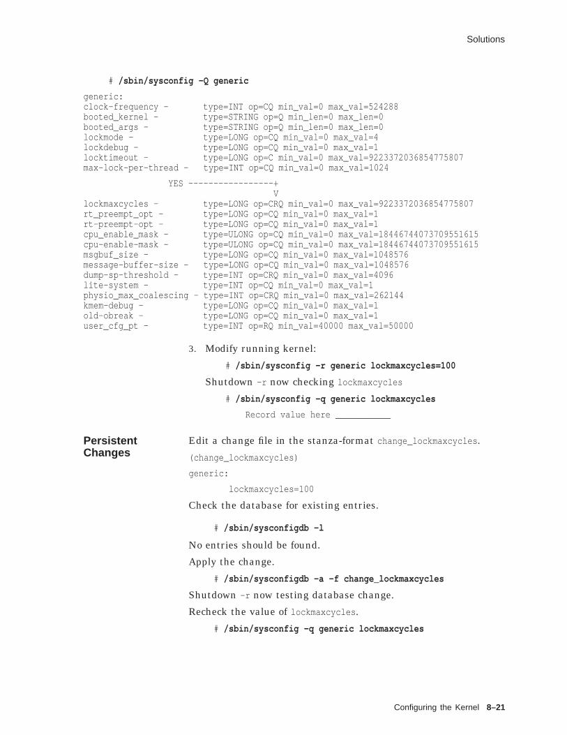
Solutions
# /sbin/sysconfig -Q generic
generic:clock-frequency - type=INT op=CQ min_val=0 max_val=524288booted_kernel - type=STRING op=Q min_len=0 max_len=0booted_args - type=STRING op=Q min_len=0 max_len=0lockmode - type=LONG op=CQ min_val=0 max_val=4lockdebug - type=LONG op=CQ min_val=0 max_val=1locktimeout - type=LONG op=C min_val=0 max_val=9223372036854775807max-lock-per-thread - type=INT op=CQ min_val=0 max_val=1024
YES -----------------+V
lockmaxcycles - type=LONG op=CRQ min_val=0 max_val=9223372036854775807rt_preempt_opt - type=LONG op=CQ min_val=0 max_val=1rt-preempt-opt - type=LONG op=CQ min_val=0 max_val=1cpu_enable_mask - type=ULONG op=CQ min_val=0 max_val=18446744073709551615cpu-enable-mask - type=ULONG op=CQ min_val=0 max_val=18446744073709551615msgbuf_size - type=LONG op=CQ min_val=0 max_val=1048576message-buffer-size - type=LONG op=CQ min_val=0 max_val=1048576dump-sp-threshold - type=INT op=CRQ min_val=0 max_val=4096lite-system - type=INT op=CQ min_val=0 max_val=1physio_max_coalescing - type=INT op=CRQ min_val=0 max_val=262144kmem-debug - type=LONG op=CQ min_val=0 max_val=1old-obreak - type=LONG op=CQ min_val=0 max_val=1user_cfg_pt - type=INT op=RQ min_val=40000 max_val=50000
3. Modify running kernel:
# /sbin/sysconfig -r generic lockmaxcycles=100
Shutdown -r now checking lockmaxcycles
# /sbin/sysconfig -q generic lockmaxcycles
Record value here ___________
PersistentChanges
Edit a change file in the stanza-format change_lockmaxcycles .
(change_lockmaxcycles)
generic:
lockmaxcycles=100
Check the database for existing entries.
# /sbin/sysconfigdb -l
No entries should be found.
Apply the change.
# /sbin/sysconfigdb -a -f change_lockmaxcycles
Shutdown -r now testing database change.
Recheck the value of lockmaxcycles .
# /sbin/sysconfig -q generic lockmaxcycles
Configuring the Kernel 8–21


9Configuring Peripherals
Configuring Peripherals 9–1

About This Chapter
About This Chapter
Introduction The system communicates with peripheral devices, such asterminals, printers, and disk drives through device drivers.These device drivers are accessed through special files. Specialfiles provide two interfaces:
• Block interface — all access is through the buffer cache
• Character interface — no kernel buffering
The Digital UNIX operating system supports two types ofconfigurable drivers:
• Traditional static drivers — configured into the system andcompiled into the kernel
• Dynamically loadable drivers — may be loaded or unloadedfrom a running system
Most devices are set up by the installation procedure. At boottime, autoconfiguration code determines which of the traditionaldevices are actually present.
To add a device to your system:
• Devices must be physically connected after the operatingsystem is shut down and the computer system is powereddown.
• When the operating system is running, you must make somechanges to system files so that the kernel will recognize thesenew devices.
A driver must be specifically designed to be dynamically loadable;it must link its interrupt handler into the interrupt table andit must create entries in the device switch tables for it to beaccessible. As vendors gain more experience with Digital UNIX,more dynamic drivers will be available. This chapter concentrateson the traditional drivers.
This chapter demonstrates how to add various peripheral devicesto the system using the MAKEDEVscript. This chapter assumes youknow how to build the kernel.
Objectives To configure peripheral devices into the system, you should beable to:
• Describe device files
• Configure terminals and pseudoterminals
• Describe the Digital UNIX LAT service
• Configure the LAT devices for a terminal server
• Describe dynamic device configuration for disk and tape drives
9–2 Configuring Peripherals

About This Chapter
• Configure printers on a Digital UNIX system using the CDEPrinter Configuration.
• Manage the print system
Resources For more information on the topics in this chapter, see thefollowing list of resources:
• Nemeth, Snyder, & Seebass, (c) 1989, UNIX SystemAdministration Handbook, Prentice-Hall, ISBN 0-13-933441-6,Chapters 7, 9, 10, 11 and 12
• Digital UNIX System Administration, Appendix A
• Digital UNIX Reference Pages, Section 7: Special Files
• Digital UNIX Network Administration, Chapters 4 and 13
Configuring Peripherals 9–3

Device Files
Device Files
Overview The special files in /dev provide access to the device drivers in thekernel.
Some devices, such as disks, have both character and block devicefiles; they prefix the character device name with an "r" for raw.
Each device is identified by a device number, which consists oftwo parts:
• Major number — identifies the driver or type of device
• Minor number — interpreted by the driver; usually identifiesthe particular device; often called the unit number
The major number is used as an index into the cdevsw table forcharacter devices or bdevsw table for block devices. Each entry inthese tables contains entry points for the associated driver code.
The minor number may set a particular characteristic of thedevice. For example, a tape drive may use minor numbers torepresent various recording densities.
Special files in /dev provide access to devices. Example 9–1 showssome special files in the /dev directory.
Example 9–1 The /dev Directory
# file /dev/*
/dev/MAKEDEV: /sbin/sh shell script -- commands text/dev/MAKEDEV.log: ascii text/dev/SYSV_PTY: /sbin/sh shell script -- commands text/dev/atm_cmm: character special (47/0)/dev/audit: character special (17/0)/dev/binlogdmb: socket/dev/cam: character special (30/0)/dev/console: character special (0/0) VS_SLU #0 GRAPHICS terminal #0/dev/kbinlog: character special (31/0)/dev/kcon: character special (3/1)/dev/keyboard0: character special (25/1) VS_SLU #0 LK401 terminal #1/dev/klog: character special (3/0)/dev/kmem: character special (2/1)/dev/lat: directory/dev/log: socket/dev/mem: character special (2/0)/dev/mouse0: character special (23/1) VS_SLU #0 VSXXXAA terminal #1/dev/nrmt0a: character special (9/5127) SCSI #0 TLZ06 tape #5 (SCSI ID #5)/dev/nrmt0h: character special (9/5123) SCSI #0 TLZ06 tape #5 (SCSI ID #5)/dev/nrmt0l: character special (9/5121) SCSI #0 TLZ06 tape #5 (SCSI ID #5)/dev/nrmt0m: character special (9/5125) SCSI #0 TLZ06 tape #5 (SCSI ID #5)/dev/null: character special (2/2)/dev/pfcntr: character special (26/0)/dev/pipe: character special (32/58)
(continued on next page)
9–4 Configuring Peripherals

Device Files
Example 9–1 (Cont.) The /dev Directory
/dev/prf: character special (37/0)/dev/printer: socket/dev/ptm: character special (32/7)/dev/ptmx: character special (32/63)/dev/ptmx_bsd: character special (32/7)/dev/pts: directory/dev/ptyp0: character special (7/0)/dev/ptyp1: character special (7/1)/dev/ptyp2: character special (7/2)/dev/ptyp3: character special (7/3).../dev/ptyqf: character special (7/31)/dev/rmt0a: character special (9/5126) SCSI #0 TLZ06 tape #5 (SCSI ID #5) (SCSI LUN #0)
offline/dev/rmt0h: character special (9/5122) SCSI #0 TLZ06 tape #5 (SCSI ID #5) (SCSI LUN #0)
offline/dev/rmt0l: character special (9/5120) SCSI #0 TLZ06 tape #5 (SCSI ID #5) (SCSI LUN #0)
offline/dev/rmt0m: character special (9/5124) SCSI #0 TLZ06 tape #5 (SCSI ID #5) (SCSI LUN #0)
offline
/dev/rrz0a: character special (8/0)/dev/rrz0b: character special (8/1)/dev/rrz0c: character special (8/2)/dev/rrz0d: character special (8/3)/dev/rrz0e: character special (8/4)/dev/rrz0f: character special (8/5)/dev/rrz0g: character special (8/6)/dev/rrz0h: character special (8/7)/dev/rrz1a: character special (8/1024)/dev/rrz1b: character special (8/1025)/dev/rrz1c: character special (8/1026)
(continued on next page)
Configuring Peripherals 9–5
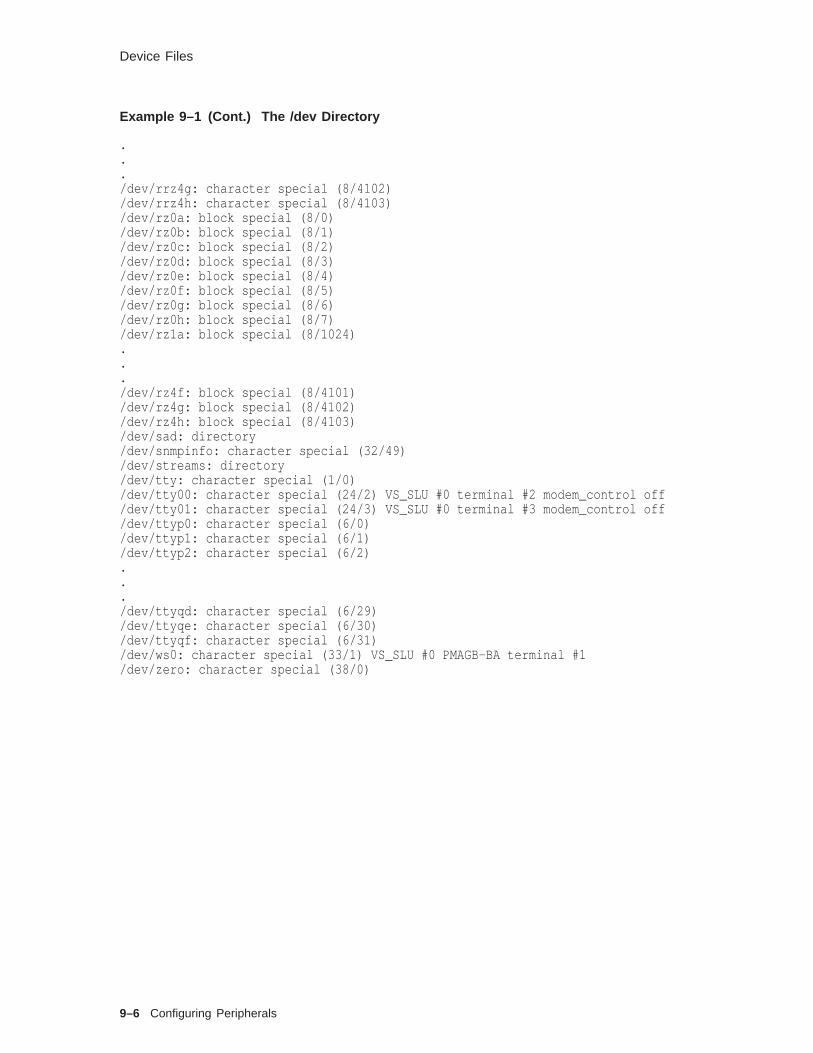
Device Files
Example 9–1 (Cont.) The /dev Directory
.
.
./dev/rrz4g: character special (8/4102)/dev/rrz4h: character special (8/4103)/dev/rz0a: block special (8/0)/dev/rz0b: block special (8/1)/dev/rz0c: block special (8/2)/dev/rz0d: block special (8/3)/dev/rz0e: block special (8/4)/dev/rz0f: block special (8/5)/dev/rz0g: block special (8/6)/dev/rz0h: block special (8/7)/dev/rz1a: block special (8/1024).../dev/rz4f: block special (8/4101)/dev/rz4g: block special (8/4102)/dev/rz4h: block special (8/4103)/dev/sad: directory/dev/snmpinfo: character special (32/49)/dev/streams: directory/dev/tty: character special (1/0)/dev/tty00: character special (24/2) VS_SLU #0 terminal #2 modem_control off/dev/tty01: character special (24/3) VS_SLU #0 terminal #3 modem_control off/dev/ttyp0: character special (6/0)/dev/ttyp1: character special (6/1)/dev/ttyp2: character special (6/2).../dev/ttyqd: character special (6/29)/dev/ttyqe: character special (6/30)/dev/ttyqf: character special (6/31)/dev/ws0: character special (33/1) VS_SLU #0 PMAGB-BA terminal #1/dev/zero: character special (38/0)
9–6 Configuring Peripherals

Configuring Terminals
Configuring Terminals
ConfiguringTerminals
This section describes how to configure terminals andpseudoterminals.
You should log in as root for this procedure. Look at the genericsystem configuration file for sample device definition lines.
To add terminals to your system, use the following procedure:
1. If the controller driver is not dynamically loadable, add thedevice definition to the system configuration file and rebuildthe kernel. See the Reference Pages for the device for a samplespecification.
2. Connect the controller:
a. Shut down and power off the system.
b. Install the controller.
c. Power up and boot the system.
3. Change to the /dev directory and create the special files usingthe MAKEDEV(8) command in the following format:
MAKEDEVdevice#
device is the device mnemonic name for the terminalmultiplexer you are adding. # is the device unit number.
4. Add the new tty lines to the /etc/inittab (4) file using thefollowing format:
tty : run-level : action : command
Enable the terminal line for run levels 2 and 3. The respawnaction causes init to restart the command if it does not exist;the off action causes init to terminate the command if it isrunning. The command for terminals is generally the getty (8)command. For example, the first line enables tty02 for runlevels 2 and 3, and the second line disables logins on tty03 .
tty02:23:respawn:/usr/sbin/getty /dev/tty02 9600 vt100tty03:23:off:/usr/sbin/getty /dev/tty03 9600 vt100
5. To allow root logins on a terminal, add the new tty line to the/etc/securettys file. For example:
/dev/tty08/dev/tty09/dev/tty10
6. Force init to reexamine the inittab file and initialize the ttylines:
# init q
The MAKEDEVshell script is a front-end to the mknod(8) command; itprovides default values.
Configuring Peripherals 9–7

Configuring Terminals
ConfiguringPseudoterminals
Pseudoterminals, unlike terminals, have no correspondingphysical terminal port on the system. Pseudoterminals use twofiles - pty (master) and tty (slave). Pseudoterminals are usedby remote login sessions, window-based software, and shells foraccess to a system.
Digital UNIX offers two implementations of pseudoterminals:BSD STREAMS amd BSD clist . See System Administration,Chapter 5 for more information.
To add pseudoterminals to your system, use the followingprocedure:
1. Use pty and nptys with sysconfigtab to increase the numberof pseudoterminals if needed. By default, the kernel supports255 pseudoterminals.
2. Boot the new kernel.
3. Change to the /dev directory and create the special files usingthe MAKEDEV(8) command in the following format:
MAKEDEV pty#
# represents the set of pseudoterminals you want to create.For example, if you already have pty sets 0 and 1, create pty2.MAKEDEVwill list the files it creates.
# MAKEDEV pty2MAKEDEV: special file(s) for pty2:ptyr0 ttyr0 ptyr1 ttyr1 ptyr2 ttyr2 ptyr3 ttyr3 ptyr4 ttyr4 ptyr5ttyr5 ptyr6 ttyr6 ptyr7 ttyr7 ptyr8 ttyr8 ptyr9 ttyr9 ptyra ttyraptyrb ttyrb ptyrc ttyrc ptyrd ttyrd ptyre ttyre ptyrf ttyrf
4. To allow root logins on all pseudoterminals, add an entry forptys to the /etc/securettys file.
9–8 Configuring Peripherals
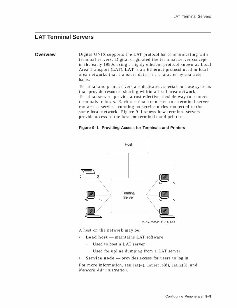
LAT Terminal Servers
LAT Terminal Servers
Overview Digital UNIX supports the LAT protocol for communicating withterminal servers. Digital originated the terminal server conceptin the early 1980s using a highly efficient protocol known as LocalArea Transport (LAT). LAT is an Ethernet protocol used in localarea networks that transfers data on a character-by-characterbasis.
Terminal and print servers are dedicated, special-purpose systemsthat provide resource sharing within a local area network.Terminal servers provide a cost-effective, flexible way to connectterminals to hosts. Each terminal connected to a terminal servercan access services running on service nodes connected to thesame local network. Figure 9–1 shows how terminal serversprovide access to the host for terminals and printers.
Figure 9–1 Providing Access for Terminals and Printers
Host
ZKOX−055000111−14−RGS
TerminalServer
A host on the network may be:
• Load host — maintains LAT software
Used to boot a LAT server
Used for upline dumping from a LAT server
• Service node — provides access for users to log in
For more information, see lat (4), latsetup (8), latcp (8), andNetwork Administration.
Configuring Peripherals 9–9

Adding Terminals on a Terminal Server
Adding Terminals on a Terminal Server
ConfiguringLAT Devices
Digital UNIX systems support terminal servers using the LATprotocol.
To configure the LAT devices, use the following procedure:
1. Verify that options LAT is in your system configuration file.If you use doconfig to build the kernel, the option should bethere as soon as the lat subsets are installed. If not, add it,rebuild, and boot the new kernel.
2. Use latsetup to create the LAT device special files and startthe LAT.
You should log in as root for this procedure.
The following table summarizes the latsetup versus manualmethod.
latsetup Manual Method
Creates sets of 16 LATdevice special files
MAKEDEV latn
Adds the new tty lines to/etc/inittab
For example, latty0a:234:respawn:/usr/sbin/getty /dev/tty0a then useinit q to make changes take effect
Creates the STREAMSspecial file /dev/streams/kinfo
strsetup -i
Sets the LAT_SETUPvariablein /etc/rc.config to 1 forautomatic startup
rcmgr set LAT_SETUP 1
Starts the LAT service latcp -s
Runninglatsetup
The latsetup command provides an interactive, menu-drivenfacility for administering LAT on your system. The following is anexample of a session to set up LAT. User selections are boldface.
Example 9–2 Using the latsetup Utility
# latsetup
LAT Setup Utility
The latsetup program provides assistance in setting up LAT on your system.If this is the first time running latsetup on this system, it is recommendedto select the Initial LAT Setup option.
(continued on next page)
9–10 Configuring Peripherals
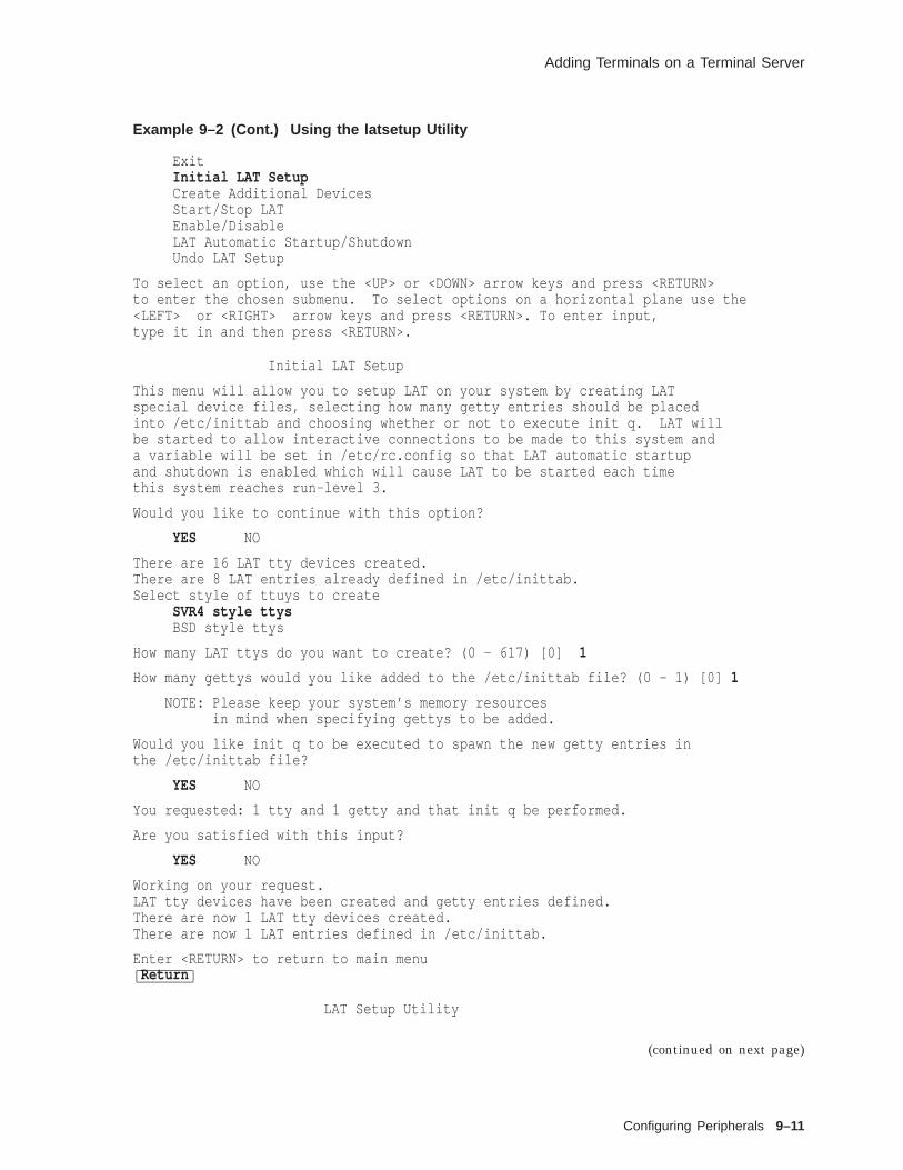
Adding Terminals on a Terminal Server
Example 9–2 (Cont.) Using the latsetup Utility
ExitInitial LAT SetupCreate Additional DevicesStart/Stop LATEnable/DisableLAT Automatic Startup/ShutdownUndo LAT Setup
To select an option, use the <UP> or <DOWN> arrow keys and press <RETURN>to enter the chosen submenu. To select options on a horizontal plane use the<LEFT> or <RIGHT> arrow keys and press <RETURN>. To enter input,type it in and then press <RETURN>.
Initial LAT Setup
This menu will allow you to setup LAT on your system by creating LATspecial device files, selecting how many getty entries should be placedinto /etc/inittab and choosing whether or not to execute init q. LAT willbe started to allow interactive connections to be made to this system anda variable will be set in /etc/rc.config so that LAT automatic startupand shutdown is enabled which will cause LAT to be started each timethis system reaches run-level 3.
Would you like to continue with this option?
YES NO
There are 16 LAT tty devices created.There are 8 LAT entries already defined in /etc/inittab.Select style of ttuys to create
SVR4 style ttysBSD style ttys
How many LAT ttys do you want to create? (0 - 617) [0] 1
How many gettys would you like added to the /etc/inittab file? (0 - 1) [0] 1
NOTE: Please keep your system’s memory resourcesin mind when specifying gettys to be added.
Would you like init q to be executed to spawn the new getty entries inthe /etc/inittab file?
YES NO
You requested: 1 tty and 1 getty and that init q be performed.
Are you satisfied with this input?
YES NO
Working on your request.LAT tty devices have been created and getty entries defined.There are now 1 LAT tty devices created.There are now 1 LAT entries defined in /etc/inittab.
Enter <RETURN> to return to main menuReturn
LAT Setup Utility
(continued on next page)
Configuring Peripherals 9–11

Adding Terminals on a Terminal Server
Example 9–2 (Cont.) Using the latsetup Utility
The latsetup program provides assistance in setting up LAT on your system.If this is the first time running latsetup on this system, it is recommendedto select the Initial LAT Setup option.
ExitInitial LAT SetupCreate Additional DevicesStart/Stop LATEnable/DisableLAT Automatic Startup/ShutdownUndo LAT Setup
#
Controlling theLAT Service
The latcp command controls and manages the LAT terminalservice. It allows you to start and stop LAT service and modifyand display configuration characteristics. Some latcp options:
-d Displays LAT host name and status information
-s Starts LAT service; enables connections from LATterminal servers to host
-h Halts LAT service
-g group ,... Adds group codes to the groups enabled for yourhost
-P tty ,... Sets a list of tty s as being available only forhost-initiated connections
For example, to set up a host-initiated connection for a printerconnected to a terminal server port:
latcp -A -P tty -H node -R port [-Q]
• tty is the tty device to associate with the printer
• node is the name of the terminal server where the printer isconnected
• port is the name of the port on the terminal server
• -Q does not queue requests if the port is busy
The latcp command on Digital UNIX is similar to lcp on ULTRIX.
An alternative to the example is to specify the node and port inthe /etc/printcap file. Do not specify them in both places.
9–12 Configuring Peripherals

Configuring Disk and Tape Drives
Configuring Disk and Tape Drives
Overview Dynamic Device Recognition (DDR) is a framework thatdescribes the operating parameters and characteristics of SCSIdevices to the SCSI CAM I/O subsystem.
Beginning with Digital UNIX V4.0 it is the preferred method forrecognizing SCSI devices over the static method for recognizingdevices. Using this new method, DDR will modify the SCSICAM system to extract as much information as possible from adevice rather than depending on statically compiled tables. Thisprovides the following benefits:
• Devices are automatically recognized
• Static configuration is not required
• The system does not require a reboot
• Enhanced user system availability occurs
DDROperations
The default text database file is initially populated on thesoftware distribution, and is used when the system is booted atinstallation to produce the binary database used by the kernel.Changes to the database might be required under the followingconditions:
• Devices are not compatible with the SCSI-2 standard, thusrequiring different characteristics to be placed in the database
• Optimization of device defaults
Modification steps:
1. Device characteristic changes are edited into the text databasefile /etc/ddr.dbase .
2. The ddr_config utility is invoked to read the text file.
3. Assuming no error in the format, the binary output is placedinto the binary database /etc/ddr.db .
4. The ddr_config utility notifies the kernel of the newmodification.
5. The kernel then synchronizes its in-memory device tables withthe definitions in the binary database file.
Since this mechanism is dynamic, devices may be automaticallyconfigured into the kernel. Special handling with the ddr_configutility is only required for nonstandard devices.
Modification Procedures
Refer to the System Administration Manual Chapter 5 forprocedural task details to modify the binary database.
Configuring Peripherals 9–13

Configuring a Printer with CDE Printer Configuration
Configuring a Printer with CDE Printer Configuration
Overview Digital UNIX Version 4.0 systems with graphics capability willload and configure the new Common Desktop Environment (CDE)automatically at boot time. This enables the user to invoke theCDE Printer Configuration system administration application.This application is used primarily to configure printers in thefollowing ways:
• Add a printer
• Modify a printer
• Select a printer for the system default printer
• Deconfigure a printer
This is the recommended way of configuring a printer in theDigital UNIX print system.
Note that the CDE Printer Configuration does not have theability to control printers other than for the initial configuration.These controls reside in the traditional utility lpc or CDE PrinterManager application to manage print jobs and queues.
Using theCDE PrinterConfiguration
The CDE Printer Configuration is invoked in the same manner asthe other applications in the Application Manager - Configurationwindow. Double-click the Print icon. At this point, the GetPassword Pop-up window is displayed and you must enter theroot password to continue.
Figure 9–2 Starting Printer Configuration
9–14 Configuring Peripherals
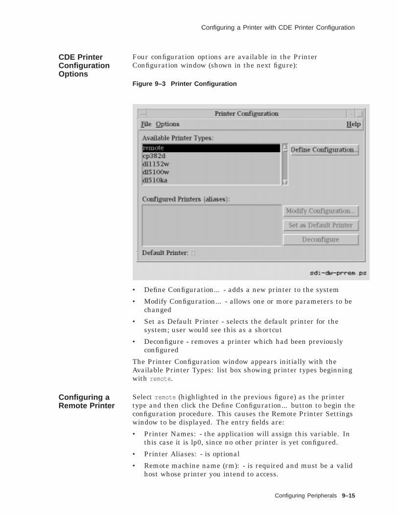
Configuring a Printer with CDE Printer Configuration
CDE PrinterConfigurationOptions
Four configuration options are available in the PrinterConfiguration window (shown in the next figure):
Figure 9–3 Printer Configuration
• Define Configuration... - adds a new printer to the system
• Modify Configuration... - allows one or more parameters to bechanged
• Set as Default Printer - selects the default printer for thesystem; user would see this as a shortcut
• Deconfigure - removes a printer which had been previouslyconfigured
The Printer Configuration window appears initially with theAvailable Printer Types: list box showing printer types beginningwith remote .
Configuring aRemote Printer
Select remote (highlighted in the previous figure) as the printertype and then click the Define Configuration... button to begin theconfiguration procedure. This causes the Remote Printer Settingswindow to be displayed. The entry fields are:
• Printer Names: - the application will assign this variable. Inthis case it is lp0, since no other printer is yet configured.
• Printer Aliases: - is optional
• Remote machine name (rm): - is required and must be a validhost whose printer you intend to access.
Configuring Peripherals 9–15

Configuring a Printer with CDE Printer Configuration
• Remote printer name (rp): - must be a valid printer configuredon the remote host.
Figure 9–4 Remote Printer Settings
You must click the Commit button to complete the configurationeven if you did not make changes. The CDE Printer Configurationwill set all required parameters based on the type of printerselected.
TheAdvanced...Button
The Advanced... button displays the Advanced Remote PrinterSettings window where the user can:
• Enter comments about the printer
• Change one or more default parameters
In this example the comment 2cents werth has already beenentered. The second comment testing is ready to be added byclicking the Add button.
9–16 Configuring Peripherals

Configuring a Printer with CDE Printer Configuration
Figure 9–5 Advanced Remote Printer Settings Window
There are five variables used for configuring this remote printer.The Error Log File Name (lf): entry field and the Spoolingdirectory (sd): entry field are filled in by the application.
The Max file size (mx): entry field is left empty by default. In thiscase, 0 was entered to indicate that there is no maximum file sizeimposed on any files sent to the remote printer.
Click OK when all option entries are correct. This will dismissthe Advanced Remote Printer Settings window and bring the userback to the Remote Printer Settings window. Click the Commitbutton to complete the configuration.
The/etc/printcapFile
When a file is scheduled to be printed the print daemon will scanthe /etc/printcap file to determine printer characteristics. Theentry in this file is created by the CDE Printer Configurationapplication when the user clicks on the Commit button of theRemote Printer Settings window. The contents of this file areshown below using the more /etc/printcap command.
Configuring Peripherals 9–17

Configuring a Printer with CDE Printer Configuration
$ more /etc/printcap# 2cents worthlp0|0|don:\
:lf=/usr/adm/lp0err:\:lp=:\:mx#0:\:rm=2cents:\:rp=worth:\:sd=/usr/spool/lpd0:
printcap: END
Configuring aLocal Printer
When the printer type selected is any other than remote (in thePrinter Configuration window), a local printer setup is assumedand the Local Printing Settings window is displayed. The PrinterNames: entry field is automatically filled with lp1,1 ; because thisis the second printer to be configured. It is given an alias whichhelps to identify it and make life simple for the user.
A new setting (not used when setting remote printer variables) isthe Connection type (ct):. This has a choice of two radio buttons.
First is the Direct connection implying either a serial or parallelconnection directly to this host. The other button is a local areatransport (LAT) connection which is chosen for this example.
Figure 9–6 Local Printer Settings Window
The LAT specification: toggle buttons allow you one of twochoices:
• by Port - this is the selection to use a singularly defined porton a LAT server.
9–18 Configuring Peripherals

Configuring a Printer with CDE Printer Configuration
• by Service - defines a service where more than one port isconfigured. This is used to construct a pool of printers wherea print job would be queued to an idle printer.
In this example the by Port toggle button is chosen and PrinterConfiguration assigns a default in the Device pathname (lp):entry field. The user must enter the LAT server nodename (Ts):and the Port name (Op):. In this case, 22prnt is the the Port namewhich is already defined and the single port on the chosen LATserver 3cents .
The Advanced... button is used to either examine the printercharacteristic settings or modify them. In the next figure, theAccounting file name (af): entry field is filled by the PrinterConfiguration as well as the Stty baud rate (br): entry field.Other characteristics are visible using the vertical scroll bar.
Figure 9–7 Advanced Local Printer Settings
Configuring Peripherals 9–19

Configuring a Printer with CDE Printer Configuration
Local Printer/etc/printcap
As with the remote printer configuration, the /etc/printcap fileneeds to be updated. Shown here are all the characteristics forthe printer lp1; an lno3r located at pole 2-2.
# ln03r# pole 2-2lp1|1|ln03:\
:af=/usr/adm/lp1acct:\:br#9600:\:ct=lat:\:fc#0177777:\:fs$03::if=/usr/lbin//n03rof:\:if=/usr/adm/lp1err:\:lp=/dev/lat/636:\:mc#20:\:mx#0:\:of=/usr/1bin/ln03rof:\:pl#66:\:pw#80:\:rw:\:sd=/usr/spool/lpd1:\:xc#0177777:\:xf=/usr/lbin/xf:\:xs#044000:\:Op=22prnt:\:Ts=3cents
printcap: END
The br parameter specifies the baud rate for the printer. Thebaud rate is dependent upon the printer hardware. Consultyour printer hardware manual for the correct baud rate. The brparameter is only applicable for tty devices, that is, serial. Thisparameter has no effect on printers connected to the console portor to printers connected on a parallel port.
9–20 Configuring Peripherals
Managing the Print System
Managing the Print System
How PrintingWorks
The print system on Digital UNIX is a combination of theUNIX System V print system and the BSD UNIX print system.Some commands from UNIX System V : lp (1), lpstat (1). Somecommands from BSD UNIX: lpr (1), lpq (1), lprm (1), lpc (8).
On Digital UNIX systems, printing is controlled by the lpd (8)printer daemon.
• lpd manages a printer spooling system, where a file is placedin a queue or spooling directory until the printer can print it.
• lpd is usually started when the system goes into multiusermode.
It prints any files that were not printed before shutdown.
It then waits for print requests.
• When you use lpr (1) to print a file, it activates the lpddaemon, and it copies the file to the printer’s spoolingdirectory.
Control (cf ) file specifies the name of the user file to beprinted and printing instructions.
Data (df ) file contains the formatted text to be printed.
• lpd forks a copy of itself to handle the request.
Even though lpd is running on the system, there is nodaemon present on the queue until a print request issubmitted and lpd forks.
lpd reads the /etc/printcap file to determine printercharacteristics.
If the printer is remote, lpd communicates with the lpdon the remote system, transfers the data and control filesthere, then deletes the local copies.
lpd scans the spooling directory for a lock file.
* Contains the process identification number of thedaemon currently printing a file and the control filename.
* If there is no lock file, lpd can create the lock file andprint the first file in the queue.
* The lock file prevents two daemons from working onthe same printer queue.
lpd also maintains a status file describing the currentprinter status.
After a file has been printed, lpd removes the control anddata files and updates the status file.
Configuring Peripherals 9–21

Managing the Print System
This lpd exists as long as there are files in this queue.
Print SystemControlCommands
The following table lists the main commands to control the printsystem.
Table 9–1 Print System Commands
Command Function
lp (1) Creates a print request
lpr (1) Creates a print request
lpq (1) Displays a printer queue
lprm (1) Removes print requests from a queue
lpstat (1) Displays printer status
lpc (8) Enables or disables a printer or printer queue;rearranges the order of jobs in a queue; checks thestatus of a printer, a queue and the printer daemon
lptest (8) Generates a test pattern
CDE PrintManager
Displays print job status, finds a print job (amongknown printers), and allows user to select printersto be displayed in the Print Manager window
See the Reference Pages for more information.
Note
PrintServer printers require special software.
Usingthe lptestCommand
The lptest (8) command generates a ripple test pattern ofprintable ASCII characters to standard output. It can be used byanyone to test terminals and printers.
The format for the lptest command is:
lptest [ length [ count ]]
• length specifies the length of the output line; default is 79characters.
• count specifies the number of output lines; default is 200 lines.
When count is specified, length must also be specified.
To send the test pattern to a printer, you can redirect standardoutput
# lptest > /dev/tty02# lptest | lpr - -P2
The following is an example of the lptest command.
9–22 Configuring Peripherals

Managing the Print System
Example 9–3 Using the lptest Command
# lptest 45 10!"#$%&’()*+,-./0123456789:;<=>?@ABCDEFGHIJKLM"#$%&’()*+,-./0123456789:;<=>?@ABCDEFGHIJKLMN#$%&’()*+,-./0123456789:;<=>?@ABCDEFGHIJKLMNO$%&’()*+,-./0123456789:;<=>?@ABCDEFGHIJKLMNOP%&’()*+,-./0123456789:;<=>?@ABCDEFGHIJKLMNOPQ&’()*+,-./0123456789:;<=>?@ABCDEFGHIJKLMNOPQR’()*+,-./0123456789:;<=>?@ABCDEFGHIJKLMNOPQRS()*+,-./0123456789:;<=>?@ABCDEFGHIJKLMNOPQRST)*+,-./0123456789:;<=>?@ABCDEFGHIJKLMNOPQRSTU*+,-./0123456789:;<=>?@ABCDEFGHIJKLMNOPQRSTUV#
Using the lpcCommand
lpc (8) is the line printer control program.
Configuring Peripherals 9–23

Managing the Print System
Table 9–2 Line Printer Control Commands
lpc Command Function
abort {all | printer } Terminates an active spooling daemon on the local host,then disables printing (preventing new daemons fromstarting). This is usually used with start to restart ahung printer daemon (that is, lpq reports daemon present,but nothing is printing).
disable {all | printer } Turns off the queue(s). (Sets group execute permission onthe lock file.)
enable {all | printer } Allows spooling on the queue(s). (Removes group executepermission on the lock file.)
stop {all | printer } Stops the daemon after the current job completes anddisables printing. (Sets owner execute permission on thelock file.)
start {all | printer } Enables printing and starts a daemon for the printer(s).(Removes owner execute permission on the lock file.)
restart {all | printer } Attempts to start a new daemon. This is useful when thedaemon fails unexpectedly, leaving jobs in the queue (andlpq reports "No daemon present").
status [ printer ] Displays the status of daemons and queues.
up [all | printer ] Enables queuing and printing and starts a new daemon.
topq printer [ job ] [ user ] Moves jobs to the top of the printer queue.
You need queuing enabled and printing enabled in order to print.
The following example shows some typical lpc commands and theresulting lpc response.
9–24 Configuring Peripherals

Managing the Print System
Example 9–4 Using the lpc Command
# lpc statlp:
printer is on device ’/dev/tty00’ speed 4800queuing is enabledprinting is enabledno entriesno daemon present
# lpclpc> disable lplp:
queuing disabledlpc> statlp:
printer is on device ’/dev/tty00’ speed 4800queuing is disabledprinting is enabledno entriesno daemon present
lpc> q#
Configuring Peripherals 9–25

Summary
Summary
Device Files Special files in /dev provide access to devices.
Each device is identified by a device number, which consists oftwo parts:
• Major number — identifies the driver or type of device
• Minor number — interpreted by the driver; usually identifiesthe particular device; often called the unit number
ConfiguringTerminals
To add terminals to your system on a statically configured driver:
• Add the device definition to the system configuration file andrebuild the kernel.
• Shutdown the system and connect the controller.
• Create the special files using MAKEDEV(8).
• Add the new tty lines to the /etc/inittab (4) file.
• Add the new tty lines to the /etc/ttys (4) file.
To add a set of 16 pseudoterminals to your system:
• Increase the value in the pseudo-device pty entry in thesystem configuration file and rebuild the kernel.
• Create the special files using MAKEDEV(8).
• Add the new tty lines to the /etc/ttys (4) file.
LAT TerminalServers
Digital UNIX supports the LAT protocol for communicating withterminal servers.
AddingTerminals ona TerminalServer
To configure the LAT devices, use the following procedure.
1. Verify that options LAT is in your system configuration file. Ifnot, add it, rebuild and boot the new kernel.
2. Use latsetup to create the LAT device special files and startthe LAT.
The latcp command is used to control and manage the LATterminal service. It allows you to start and stop LAT service,modify and display configuration characteristics.
ConfiguringDisks and TapeDrives
To add a disk or tape drive with a statically configured driver:
• Shut down the system and connect the device.
• Boot the generic kernel /genvmunix .
• Add the device definition to the system configuration file andrebuild the kernel.
• Create the special files using the MAKEDEV(8) command.
9–26 Configuring Peripherals

Summary
Configuring aPrinter with theCDE PrinterConfiguration
Digital UNIX Version 4.0 systems with graphics capability willload and configure the new Common Desktop Environment (CDE)automatically at boot time. This enables the user to invoke theCDE Print Manager system administration application. Thisapplication is used primarily to configure printers in the followingways:
• Add a printer
• Modify a printer
• Select a printer for the system default printer
• Deconfigure a printer
Managing thePrint System
On Digital UNIX systems, printing is controlled by the lpd (8)printer daemon, which manages a spooling system.
There are a number of commands to control the print system:
Command Function
lp (1) Creates a print request
lpr (1) Creates a print request
lpq (1) Displays a printer queue
lprm (1) Removes print requests from a queue
lpstat (1) Displays printer status
lpc (8) Enables or disables a printer or printer queue;rearranges the order of jobs in a queue; checksthe status of a printer, a queue, and the printerdaemon
lptest (8) Generates a test pattern
Configuring Peripherals 9–27

Exercises
Exercises
Device Files 1. Bring your system to console level and invoke the helpcommand.
2. Issue the command(s) to show the devices on the system andboot the system.
ConfiguringTerminals
1. Check the ttys (4) man page.
a. What are the possible values for the third field?
b. What would be the entry for ttyq5 allowing root to log in?
2. If your system allows a terminal controller option, useMAKEDEV(8) to create the device files and add the new entries tothe inittab (4) file.
3. Create the next set of pseudoterminals.
4. Change the status of the following terminal lines:
a. Enable root logins on tty02
b. Disable logins on tty03
AddingTerminals ona TerminalServer
1. Verify that Options LAT is in your system configuration file.
2. Run latsetup and create a set of LAT devices.
DynamicDeviceRecognition
Disk and tape devices are automatically configured. Check thedrives configured in your system configuration file.
1. Check the drives found in your /etc/ddr.dbase file.
2. Check the drives configured in your system configuration file.
Adding aPrinter withCDE PrinterConfiguration
1. Add a remote printer and remove the size restriction.
2. Add a local printer configured on a LAT server.
Note
Your instructor will give you the host names, print queuenames, and baud rates to use for the available classroomprinters.
9–28 Configuring Peripherals

Exercises
Managing thePrint System
1. Use the lptest (8) command.
a. Try lptest without options.
b. Generate a test pattern 65 characters wide and 25 lineslong.
c. Generate a test pattern 10 lines long.
d. If a printer is available on your system, redirect outputfrom the test to the printer.
2. Use the lpc (8) command.
a. Check the status.
b. Disable queuing on one printer.
c. Disable printing on that printer.
d. Enable queuing.
e. Enable printing.
f. Enable everything and restart the daemon (up command).
Configuring Peripherals 9–29

Solutions
Solutions
Device Files 1. Power up the system or shut down and halt the system. Youshould see the prompt >>>. Type help .
2. On an Alpha AXP system, use the commands:
show configshow device
ConfiguringTerminals
1.
a. none for terminal lines and network for pseudoterminallines
b.
ttyq5 none network secure
ttyq5 is a pseudoterminal line
2.
# cd /dev# MAKEDEV mdc0MAKEDEV: special file(s) for mdc0:tty02 tty03 tty04 tty05 tty06 tty07 tty08 tty09 tty10 tty11# vi /etc/inittab
.
.
.tty02:23:respawn:/usr/sbin/getty /dev/tty02 9600 vt100tty03:23:respawn:/usr/sbin/getty /dev/tty03 9600 vt100
.
.
.tty11:23:respawn:/usr/sbin/getty /dev/tty11 9600 vt100
3.
# cd /dev# MAKEDEV pty2MAKEDEV: special file(s) for pty2:ptyr0 ttyr0 ptyr1 ttyr1 ptyr2 ttyr2 ptyr3 ttyr3 ptyr4 ttyr4 ptyr5ttyr5 ptyr6 ttyr6 ptyr7 ttyr7 ptyr8 ttyr8 ptyr9 ttyr9 ptyra ttyraptyrb ptyrb ptyrc ttyrc ptyrd ttyrd ptyre ttyre ptyrf ttyrf
4.
a. Edit /etc/securettys for the entry tty02 none none secure
b. Edit /etc/inittab for the entry tty03:23:off:/usr/sbin/getty /dev/tty03 9300 vt100
9–30 Configuring Peripherals

Solutions
AddingTerminals ona TerminalServer
1.
# grep LAT /sys/conf/TINKERoptions LAT
2. See the example in the text.
DynamicDeviceRecognition
1. # more /etc/ddr.dbase
2. # grep drive /sys/conf/yourhostname
Adding aPrinter withCDE PrinterConfiguration
1. Similar to the "remote" example in the text.
2. See the local printer example in the text.
Managing thePrint System
1. Use lptest
a.
# lptest!"#$%&’()*+,-./0123456789:;<=>?@ABCDEFGHIJKLMNOPQRSTUVWXYZ[\]^_‘abcdefghijklmno"#$%&’()*+,-./0123456789:;<=>?@ABCDEFGHIJKLMNOPQRSTUVWXYZ[\]^_‘abcdefghijklmnop#$%&’()*+,-./0123456789:;<=>?@ABCDEFGHIJKLMNOPQRSTUVWXYZ[\]^_‘abcdefghijklmnopq$%&’()*+,-./0123456789:;<=>?@ABCDEFGHIJKLMNOPQRSTUVWXYZ[\]^_‘abcdefghijklmnopqr%&’()*+,-./0123456789:;<=>?@ABCDEFGHIJKLMNOPQRSTUVWXYZ[\]^_‘abcdefghijklmnopqrs&’()*+,-./0123456789:;<=>?@ABCDEFGHIJKLMNOPQRSTUVWXYZ[\]^_‘abcdefghijklmnopqrst’()*+,-./0123456789:;<=>?@ABCDEFGHIJKLMNOPQRSTUVWXYZ[\]^_‘abcdefghijklmnopqrstu()*+,-./0123456789:;<=>?@ABCDEFGHIJKLMNOPQRSTUVWXYZ[\]^_‘abcdefghijklmnopqrstuv)*+,-./0123456789:;<=>?@ABCDEFGHIJKLMNOPQRSTUVWXYZ[\]^_‘abcdefghijklmnopqrstuvw
.
.
.
b.
# lptest 65 25
c.
# lptest 79 10
d.
# lptest 79 10 >/dev/lp0
2. Use lpc
Configuring Peripherals 9–31

Solutions
# lpclpc> statlp:
printer is on device ’/dev/lp’ speed -1queuing is enabledprinting is enabledno entriesno daemon is present
lpc> disable lplp:
queuing disabledlpc> stop lplp:
printing disabledlpc> enable lplp:
queuing enabledlpc> start lplp:
printing enableddaemon started
lpc> up alllp:
queuing enabledprinting enableddaemon started
lpc> q#
9–32 Configuring Peripherals

Index
Aaddress
Ethernet, 6–6Internet, 6–6
Advanced File SystemSee AdvFS
AdvFS, 2–25, 2–34ARC, 4–2ARC console, 4–7ARC Multiboot, 4–7ARP
Address Resolution Protocol, 6–6
Bbackup, 2–19, 2–24Berkeley fast file system, 2–27booting, 3–16
initializing the kernel, 3–17bootstrapping process
See bootingbroadcast message, 6–10Broadcast Message, 3–12BSD, 1–8bufcache, 8–5buffer cache, 2–26
CCDE, 1–17CDE License Manager, 7–14CDE Print Manager, 9–14CDE Shutdown, 3–11CDFS, 2–25client-server model, 6–4config, 8–6connection-oriented mode, 6–4connectionless mode, 6–4console commands, 4–6Console firmware services, 4–4cylinder, 2–5
DDailyAdmin window, 3–11DDR, 9–13device drivers, 9–2df, 7–3df(1), 2–21, 2–22disk drive
Figure, 2–4disklabel(8), 2–21, 2–22doconfig(8), 8–10dynamic configuration, 8–2, 9–2
EEdit List, 7–16Edit New, 7–16/etc/hosts, 6–7, 6–12/etc/hosts.equiv, 6–12, 6–13/etc/hosts.lpd, 6–12, 6–13/etc/inetd.conf, 6–12, 6–14/etc/inittab, 9–7/etc/networks, 6–12, 6–15/etc/printcap, 6–14, 9–21/etc/protocols, 6–12, 6–15/etc/securettys, 1–16/etc/services, 6–12, 6–16
Ffasthalt(8), 3–8FFM, 2–25File domain, 2–38File Open, 7–17Fileset, 2–39firmware update, 4–9fsck(8), 2–21, 2–22
Ggateway, 6–5getty(8), 9–7
Index–1

Hhalt(8), 3–7head, 2–5
Iinit(8), 3–8, 9–7initdefault, 3–22initialization files, 3–18
/sbin/rc*.d, 3–24Initialization files
/sbin/rc*.d, 3–26Internet Domain Name Service, 6–7IP
Internet Protocol, 6–6ISO 9660-1988, 2–25
Kkernel, 1–6, 1–7, 8–2
Mach, 1–8
LLAT, 9–9latcp(8), 9–12latsetup(8), 9–10
example, 9–10licenses required, 7–15lmf, 7–11LMF, 7–9lmfsetup, 7–12Logical Storage Manager
See LSMlp(1), 9–22lpc(8), 9–22, 9–23lpd(8), 9–21lpq(1), 9–22lpr(1), 9–22lprm(1), 9–22lpstat(1), 9–22lptest(8), 9–22LSM, 2–38
MMAKEDEV, 9–8MAKEDEV(8), 9–7maxusers, 8–5MFS, 2–25
Nnetmask, 6–10newfs(8), 2–10, 2–21, 2–22NFS, 2–25No Disk Sync, 3–13
OOSF/1, 1–8
PPAK, 7–9, 7–14partition
size change, 2–21performance
improve by dividing swap space, 2–19,2–24
improve by separating file systems, 2–19,2–24
platter, 2–4Preshutdown Script, 3–12protocol, 6–4pseudodevice, 8–6
Rreboot
methods, 3–4reboot(8), 3–9rebooting, 3–9remote installation service, 7–4.rhosts, 6–13root login, 1–15run level, 9–7
S/sbin/rc*.d, 3–24, 3–26sector, 2–5setld(8), 7–3shutdown
methods, 3–4Shutdown Manager window, 3–12shutdown(8), 3–4, 8–10software subset, 7–3special files, 9–2spooling, 9–21SRM, 4–2SRM console command list, 4–6stanza -format, 8–17static configuration, 8–2, 9–2su(1), 1–15subnetwork, 6–9
Index–2

superuser, 1–15surface, 2–4Switching from ARC to SRM, 4–8/sys/conf/GENERIC, 8–4/sys/conf/NAME, 8–4
LAT, 9–10/sys/conf/param.c, 8–4
Ttimezone, 8–5track, 2–5
UUFS, 2–25, 2–27, 2–36UNIX, 1–6user ID, 1–15
V/var/adm/sialog, 1–16VFS, 2–25vmunix, 8–10/vmunix, 1–7vnode, 2–26Volume, 2–38
Index–3


![[Stuart E. Madnick, John J. Donovan] Operating Sys(BookZa.org)](https://static.fdocuments.us/doc/165x107/55cf9801550346d03394f6e4/stuart-e-madnick-john-j-donovan-operating-sysbookzaorg.jpg)