
DTC [IL JUBY
68
DTC [IL JUBY WSRL-TR-4/89 AR005-937 a._ SIMULATING LOCAL AREA NETWORK PROTOCOLS WITH THE GENERAL PURPOSE SIMULATION SYSTEM (GPSS) N In M.L. SCHOLZ (N NCOMBAT SYSTEMS DIVISION WEAPONS SYSTEMS RESEARCH LABORATORY IDTIC ELECTE OCT2 63 Approved for Public Release. MARCH 1990 DSlOV DEPARTMENT OF DEFENCE DEFENCE SCIENCE AND TECHNOLOGY ORGANISATION 4 "90 l) 25 092
Transcript of DTC [IL JUBY

DTC [IL JUBY
WSRL-TR-4/89 AR005-937
a._SIMULATING LOCAL AREA NETWORK PROTOCOLS WITHTHE GENERAL PURPOSE SIMULATION SYSTEM (GPSS)
NIn
M.L. SCHOLZ
(NNCOMBAT SYSTEMS DIVISION
WEAPONS SYSTEMS RESEARCH LABORATORYIDTIC
ELECTE
OCT2 63
Approved for Public Release.
MARCH 1990
DSlOV DEPARTMENT OF DEFENCEDEFENCE SCIENCE AND TECHNOLOGY ORGANISATION
4 "90 l) 25 092

7£
CONDITIONS OF RELEASE AND DISPOSAL
This document is the property of the Australian Government. The informationit contains is released for defence purposes only and must not be disseminatedbeyond the stated distribution without prior approval.
Delimitation is only with the specific approval of the Releasing Authority asgiven in the Secondary Distribution statement.
This information may be subject to privately owned rights.
The officer in possession of this document is responsible for its safe custody.When no longer required the document should NOT BE DESTROYED butreturned to the Main Library, DSTO, Salisbury, South Australia.
V""

UNCLASSIFIED
DSTi I
TEC-NICAL REPORTWSRL-TR45/89
SIMULATING LOCAL AREA NETWORK PROTOCOLS WITHTHE GENERAL PURPOSE SIMULATION SYSTEM (GPSS)
M.L Scholz
SUMMARY(U)
Simulation models of ANSI 8023 (Ethernet) and ANSI 802.5 (Token Ring)transmission control protocols have been constructed to assess the usefulnessof the General Purpose Simulation System (GPSS) simulation language formodelling the performance of local area networks. The models are describedin detail and the data obtained from them are compared with analytic results.Model verification and other problems associated with analysing simulationoutput are discussed. / - ,. / 11, ~4~
© Commonwealth of Australia
Author's address:Combat Systems DivisionWeapons Systems Research LaboratoryPO Box 1700, SalisburySouth Australia
V
Requests to: Chief, Combat Systems Division
UNCLASSIFIED

WSRL-.TR-45/89
TABLE OF CONTENTS
Page
1. INTRODUCTION 1
2. ETHERNET SIMULATION MODEL 1
2.1 Model structure 2
2.1.1 Frame generation 32.1.2 Frame transmission 42.1.3 Jam and collision recovery 52.1.4 Collision sensing 62.1.5 Frame reception 7
2.2 Model artifices 8
2.3 Model variables 9
2.4 Simulation results 11
3. TOKEN RING SIMULATION MODEL 14
3.1 Model structure 15
3.1.1 Frame generation 153.1.2 Frame delivery . 15
3.2 Model artifices 16
3.3 Model variables 17
3.4 Simulation results 18
4. EXTERNAL PROCEDURES USED IN SIMULATION 19
5. MODEL VERIFICATION 20
6. SIMULATION OUTPUT ANALYSIS 21
6.1 Bias and variance reduction 21
6.2 Model execution times 22
7. DISCUSSION AND CONCLUSIONS Aoseomlon Frp 24
8. ACKNOWLEDGEMENTS IT18 W Z 25I)TIC TAB (3
ABBREVIATIONS _____________26
REFERENCES D 27
n it *"lI- Okail~~ee
WSRL-TR-45/89
Page
LIST OF FIGURES
1. Topology of a single segment Ethernet LAN 31
2. Relationship of Ethernet LAN to OSI Reference Model 32
3. Architecture of the Ethernet model 33
4. Ethernet: Frame generation process 34
5. Ethernet: Frame transmission process 35
6. Ethernet: Jam and collision recovery process 36
7. Ethernet: Collision sensing process 39
8. Ethernet: Frame reception process 40
9. Ethernet: Mean transfer delay vs mean throughput 41
10. Ethernet: Probability of zero channel assignment delay vs meanthroughput 42
11. Ethernet: Probability of buffer overflow vs mean throughput 43
12. Ethernet: Transmitter and receiver utilisations vs mean throughput 44
13. Topology of a Token Ring LAN 45
14. Relationship of Token Ring LAN to OSI Reference Model 46
15. Token Ring: Frame generation process 47
16. Token Ring: Frame delivery process 48
17. Token Ring: Mean transfer delay vs mean throughput 49
LIST OF APPENDICES
I THE ETHERNET PROTOCOL 51
Figure I.1 State diagram of Ethernet MAC transmit protocol 53
Figure 1.2 State diagram of Ethernet MAC receive protocol 54
II ANALYTIC RESULTS FOR ETHERNET PERFORMANCE 55
III THE TOKEN RING PROTOCOL 57
Figure III.1 State diagram of Token Ring MAC prntocol 58
IV ANALYTIC RESULTS FOR TOKEN RING PERFORMANCE 594,

- I - WSRL-TR-45/89
1. INTRODUCTION
The suitability of the General Purpose Simulation (GPSS) language as a toolfor modelling transmission control protocols in complex local area networks(LAN) is examined. GPSS is one of several tools under consideration forevaluating the performance of high-speed LANs that are likely to be offered inthe next generation of distributed naval combat systems. This investigationwas prompted because GPSS appears to be an ideal language for LAN protocolmodelling and because the usage of GPSS in this field has seldom been reportedin the literature.
In order to assess the potential of GPSS, two LAN protocol simulation modelswere developed with the intention of exposing the strengths and weaknesses ofthe language in this particular application. The protocols chosen were ANSI802.3(ref.14), which is very similar to the commercial "Ethernet", and ANSI802.5(ref.13), or "Token Ring" protocol. They were chosen for three reasons.Firstly, they are international (ISO and ANSI) standards and are arguably themost popular asynchronous time-division multiplexed schemes in use today fortransmitting high speed serial data in geographically distributed computersystems. Secondly, they are highly relevant to military applications.Ethernet has been adopted by many navies around the world for use in ship-board combat systems (eg Canadian Patrol Frigate, Dutch M-Frigate, West GermanMeko 200) and will be fitted to the Australian Anzac Ship. The Token Ring isimportant because it is the design upon which the current development of FDDI(Fiber Distributed Data Interface)(ref.29), a very high speed LAN, is based.FDDI will assume major importance in future military systems. Thirdly, theEthernet and Token Ring protocols have been extensively studied and thepublished performance data are adequate for the purpose of validatingsimulation models.
The GPSS simulation language has been widely employed in modelling computersystem performance(refs.10,36,37) and in manufacturing. The processinteraction approach of GPSS facilitates the efficient modelling of complexsystems that can be represented by queuing networks. This contrasts with theevent-scheduling approach of some other simulation languages, such as thepopular SIMSCRIPT II.5(ref.21), which involve much greater programming effort.Several dialects have been developed from the original IBM GPSS/Vproduct(ref.15). GPSS/H(ref.12) was chosen on the strength of its extendedprogramming features, computational efficiency, ease of understanding, andpopularity. The reader is assumed to have a basic knowledge of the language.
The remainder of this report is organised as follows. An exact GPSS/H model ofthe Ethernet protocol and an approximate model of the Token Ring protocol aredescribed in Sections 2 and 3. In Section 4, the external routines used in thesimulations are described. The facilities provided by GPSS/H for verifying theoperation of a model are described in Section 5. The major problems associatedwith simulation output analysis are addressed in Section 6. The principalconclusions regarding the suitability of GPSS/H for LAN protocol modelling arethen summarised in Section 7.
This research was undertaken with the sponsorship of the Director, NavalCombat Systems Engineering, Royal Australian Navy (Task No. NAV 87/226).
2. ETHERNET SIMULATION MODEL
Ethernet (ANSI 802.3) is a CSMA/CD (carrier sense multiple access, collisiondetection) protocol designed to operate in a LAN bus topology(ref.14). Themodel described below assumes a simple single segment topology as depicted infigure 1. More complex multiple segment topologies may also be modelled byincluding repeater delays in the inter-station propagation delays. The results
U- -
WSRL-TR-45/89 - 2 =
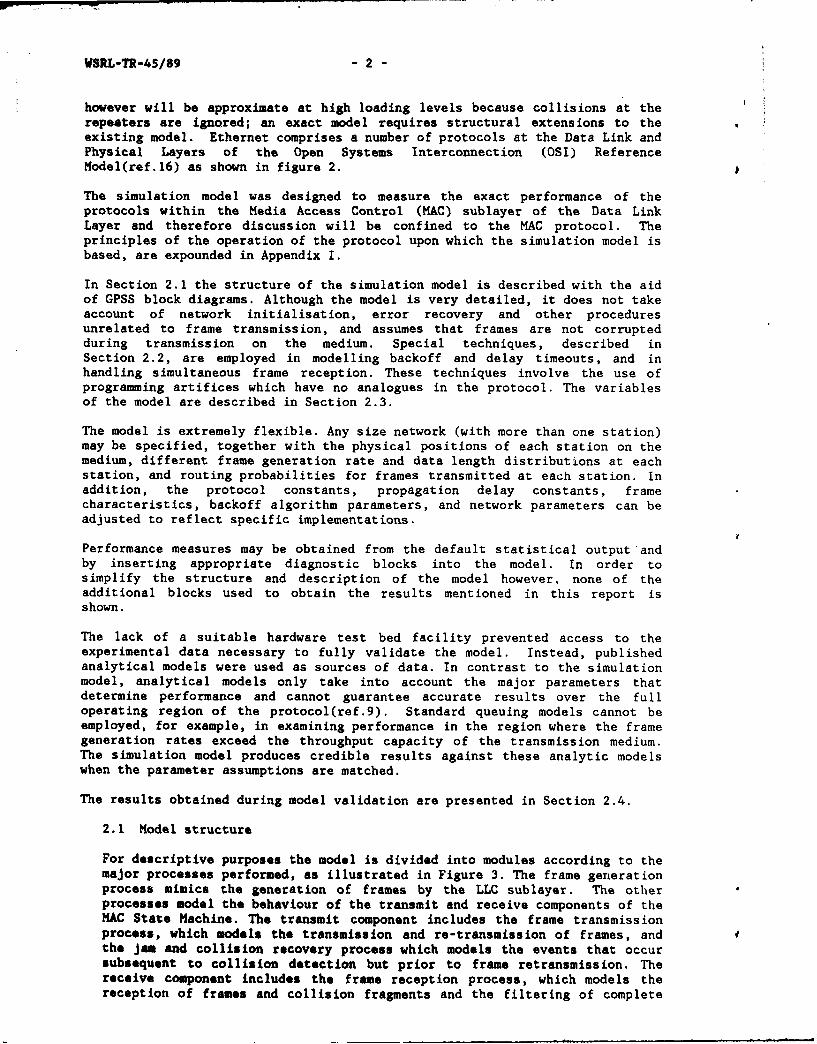
however will be approximate at high loading levels because collisions at therepeaters are ignored; an exact model requires structural extensions to theexisting model. Ethernet comprises a number of protocols at the Data Link andPhysical Layers of the Open Systems Interconnection (OSI) ReferenceModel(ref.16) as shown in figure 2.
The simulation model was designed to measure the exact performance of theprotocols within the Media Access Control (MAC) sublayer of the Data LinkLayer and therefore discussion will be confined to the MAC protocol. Theprinciples of the operation of the protocol upon which the simulation model isbased, are expounded in Appendix I.
In Section 2.1 the structure of the simulation model is described with the aidof GPSS block diagrams. Although the model is very detailed, it does not takeaccount of network initialisation, error recovery and other proceduresunrelated to frame transmission, and assumes that frames are not corruptedduring transmission on the medium. Special techniques, described inSection 2.2, are employed in modelling backoff and delay timeouts, and inhandling simultaneous frame reception. These techniques involve the use ofprogramming artifices which have no analogues in the protocol. The variablesof the model are described in Section 2.3.
The model is extremely flexible. Any size network (with more than one station)may be specified, together with the physical positions of each station on themedium, different frame generation rate and data length distributions at eachstation, and routing probabilities for frames transmitted at each station. Inaddition, the protocol constants, propagation delay constants, framecharacteristics, backoff algorithm parameters, and network parameters can beadjusted to reflect specific implementations.
Performance measures may be obtained from the default statistical output andby inserting appropriate diagnostic blocks into the model. In order tosimplify the structure and description of the model however, none of theadditional blocks used to obtain the results mentioned in this report isshown.
The lack of a suitable hardware test bed facility prevented access to theexperimental data necessary to fully validate the model. Instead, publishedanalytical models were used as sources of data. In contrast to the simulationmodel, analytical models only take into account the major parameters thatdetermine performance and cannot guarantee accurate results over the fulloperating region of the protocol(ref.9). Standard queuing models cannot beemployed, for example, in examining performance in the region where the framegeneration rates exceed the throughput capacity of the transmission medium.The simulation model produces credible results against these analytic modelswhen the parameter assumptions are matched.
The results obtained during model validation are presented in Section 2.4.
2.1 Model structure
For descriptive purposes the model is divided into modules according to themajor processes performed, as illustrated in Figure 3. The frame generationprocess mimics the generation of frames by the LLC sublayer. The otherprocesses model the behaviour of the transmit and receive components of theMAC State Machine. The transmit component includes the frame transmissionprocess, which models the transmission and re-transmission of frames, andthe jam and collision recovery process which models the events that occursubsequent to collision detection but prior to frame retransmission. Thereceive component includes the frame reception process, which models thereception of frames and collision fragments and the filtering of complete

- 3 - WSRL-TR-45/89
and correctly addressed frames, and the collision sensing process whichmodels the detection of collisions on the medium and the setting ofinternal flags that control the behaviour of the transmitter.
Because the above processes must be replicated for each station in thenetwork, structural "folding" is applied to reduce the number of blocks inthe model. A penalty must be paid however in the additional complexity ofthe logic. To facilitate folding, GPSS transaction parameters are used toassociate transactions controlling transitions in the MAC State Machinewith a particular station, and to store the MAC state variables of thatstation. In addition, transaction parameters are used to store frame-specific information, such as source and destination addresses, event times(eg frame generation time), and message length in transactions whichsimulate frames. The reference numbers of GPSS blocks (eg SEIZE, LINK,LOGIC, GATE blocks etc) which model station queues, flags, decision gates,and other station entities, are either indexed by GPSS variables (eg V$FAC)or by transaction parameters.
2.1.1 Frame generation
The frame generation process (figure 4) simulates the generation offixed length frames with Poisson distributions by the LLC sublayer. ThePoisson distribution was chosen because it frequently fits observedarrival rate statistics in operational systems and because it is almostuniversally employed in analytic LAN models. Frames arriving at the MACsublayer in conformance with this distribution are uniformly distributedthroughout a finite time interval (viz simulation run) and areindependent of previous arrivals.
The flexibility of the model permits other frame length or generationrate distributions to be employed by calling external routines toproduce random numbers at the appropriate ASSIGN blocks. Frames arerepresented by transactions in the model.
One transaction per station is generated by the first SPLIT block from asingle initial transaction arriving at zero time from the GENERATEblock. Parameter PHl associated with each of these transactions isassigned a unique value <PHl>t(1,2,. ,&N) corresponding to a stationaddress, where the ampervariable &N is the total number of stations inthe network. (Note the symbol <x> represents the numerical valueassigned to parameter "x"). Each transaction then enters an ADVANCEblock and experiences an exponentially-distributed random delay(computed by the external routine &REXPON) with a mean value equal tothe reciprocal of the station's mean frame generation rate, &MAR(PH1),before entering the second SPLIT block. Daughter transactions from thesecond SPLIT block are transferred to the previous ADVANCE block toenable the generation of subsequent frames.
Three items of frame-specific information are attached to the parenttransactions after they leave the second SPLIT block and before theyenter the frame transmission process. The random frame destinationaddress (computed by the external routine &IDEST), which is uniformlydistributed over the range of (integer) station addresses is assigned toPH2. The length of the data field contained in the frame, which isspecified as a constant, is assigned to PH4. The random frametransmission delay assigned to PLI is given by the sum of the datalength and the data length dependent frame overhead, VSOVERHEAD(multiplied by eight to convert octets to bits), divided by the datatransmission rate, &DATARATE.
WSRL-TR-45/89 - 4 -
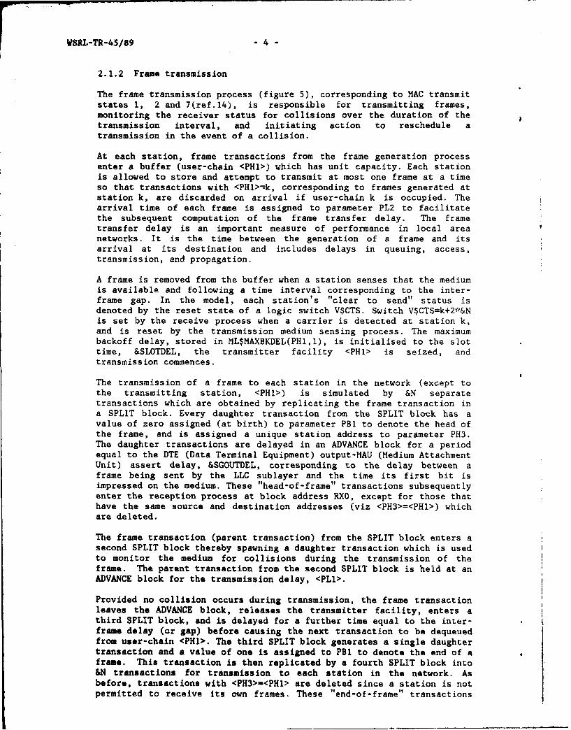
2.1.2 Frame transmission
The frame transmission process (figure 5), corresponding to MAC transmitstates 1, 2 and 7(ref.14), is responsible for transmitting frames,monitoring the receiver status for collisions over the duration of thetransmission interval, and initiating action to reschedule atransmission in the event of a collision.
At each station, frame transactions from the frame generation processenter a buffer (user-chain <PHl>) which has unit capacity. Each stationis allowed to store and attempt to transmit at most one frame at a timeso that transactions with <PHl>-k, corresponding to frames generated atstation k, are discarded on arrival if user-chain k is occupied. Thearrival time of each frame is assigned to parameter PL2 to facilitatethe subsequent computation of the frame transfer delay. The frametransfer delay is an important measure of performance in local areanetworks. It is the time between the generation of a frame and itsarrival at its destination and includes delays in queuing, access,transmission, and propagation.
A frame is removed from the buffer when a station senses that the mediumis available and following a time interval corresponding to the inter-frame gap. In the model, each station's "clear to send" status isdenoted by the reset state of a logic switch V$CTS. Switch V$CTS=k+2*&Nis set by the receive process when a carrier is detected at station k,and is reset by the transmission medium sensing process. The maximumbackoff delay, stored in ML$MAXBKDEL(PH1,1), is initialised to the slottime, &SLOTDEL, the transmitter facility <PHI> is seized, andtransmission commences.
The transmission of a frame to each station in the network (except tothe transmitting station, <PHI>) is simulated by &N separatetransactions which are obtained by replicating the frame transaction ina SPLIT block. Every daughter transaction from the SPLIT block has avalue of zero assigned (at birth) to parameter PBl to denote the head ofthe frame, and is assigned a unique station address to parameter PH3.The daughter transactions are delayed in an ADVANCE block for a periodequal to the DTE (Data Terminal Equipment) output-MAU (Medium AttachmentUnit) assert delay, &SGOUTDEL, corresponding to the delay between aframe being sent by the LLC sublayer and the time its first bit isimpressed on the medium. These "head-of-frame" transactions subsequentlyenter the reception process at block address RXO, except for those thathave the same source and destination addresses (viz <PH3>=<PH>) whichare deleted.
The frame transaction (parent transaction) from the SPLIT block enters asecond SPLIT block thereby spawning a daughter transaction which is usedto monitor the medium for collisions during the transmission of theframe. The parent transaction from the second SPLIT block is held at anADVANCE block for the transmission delay, <PLl>.
Provided no collision occurs during transmission, the frame transactionleaves the ADVANCE block, releases the transmitter facility, enters athird SPLIT block, and is delayed for a further time equal to the inter-frame delay (or gap) before causing the next transaction to be dequeuedfrom user-chain <PH1>. The third SPLIT block generates a single daughtertransaction and a value of one is assigned to PBl to denote the end of aframe. This transaction is then replicated by a fourth SPLIT block into&N transactions for transmission to each station in the network. Asbefore, transactions with <PH3>=<PHI> are deleted since a station is notpermitted to receive its own frames. These "end-of-frame" transactions

- 5 - WSRL-TR-45/89
then enter the reception process at block address RXO.
A collision occuring during or after transmission of the preambleaffects the transmission of the frame in the following manner. Thedaughter transaction from the second SPLIT block is "marked" (viz thecurrent simulator absolute clock time, ACI, is stored in thetransaction's transit delay attribute, Ml, by a MARK block) at thecommencement of transmission. It then waits at a conditional TEST blockuntil either a collision occurs (logic switch <PHI> set) or frametransmission is finished (transmitter facility <PHI> not in use). Whentransmission is complete, the transaction is deleted. If a collisionoccurs, the transaction is delayed until the preamble is finished. Themaximum delay is equal to the preamble transmission delay, &PREAMDEL.The transmit facility <PHI> is then pre-empted resulting in thetransaction located in the ADVANCE block at address TX3+4 being sent tothe jam and collision recovery process (block address TXl2).
2.1.3 Jam and collision recovery
The jam and collision recovery process (figure 6), corresponding to MACtransmit states 3 to 6, and 8 to 10(ref.14), is responsible forterminating a frame transmission in the event of a collision,transmitting a jam, and rescheduling or aborting a transmission.
A transaction enters this process from the frame transmission processfollowing a collision. It seizes the transmitter facility <PHI> and isdelayed in an ADVANCE block for a period equal to &JAMDEL whilst the jamis being transmitted, before it releases the transmitter facility. Itthen enters a SPLIT block, increments the attempt count in PH5, andtests whether the attempt count exceeds the attempt limit, &MAXATTMP.If the limit has been exceeded, the frame is aborted by returning thetransaction to the transmit frame process (at block address TX4) whereit dequeues the next frame from the buffer (viz transaction on user-chain <PHI>) before being deleted. Otherwise the attempt count iscompared with the backoff threshold, &THRESCNT. If the attempt count isless than the backoff threshold, the mean backoff delay stored inMLSMAXBKDEL(PH1,1) is doubled at each attempt in accordance with thebinary exponential backoff algorithm.
The initial and subsequent backoff delays are randomly sampled (by theexternal procedure &RUNIF) from a continuous range of values in theclosed interval [O,ML$MAXBAKDEL(PHI,I)1 and assigned to parameter PL3.The inter-frame delay is initialised to its maximum value, &IFDEL, andassigned to parameter PL4. The operation of the backoff timer and thedelay timer, which rely upon these parameters, is described inSection 2.2. The transaction then enters the backoff-delay state. Thetime of entry to this state is marked before the transaction enters aSPLIT block at address TXl4+2. If the inter-frame delay remainingexceeds the backoff delay remaining, the transaction is dispatched tothe ADVANCE block at address TXI7+I where it remains until the delaytimer expires. Otherwise, the transaction waits in the ADVANCE block ataddress TXl4+5 until the backoff timer expires, after which theremaining inter-frame delay is adjusted and the delay-wait state isentered. The station remains in the delay-wait state until thetransaction leaves the ADVANCE block at address TXi5 upon expiry of thedelay timer. The transaction re-enters the transmit process (at blockaddress TX3) to simulate the re-transmission of the frame. Upon leavingthe ADVANCE block at address TX17+l, the backoff delay remaining isadjusted and the transaction is marked before it enters the backoffstate.

WSRL-TR-45/89 - 6 -
The daughter transaction leaving the SPLIT block at address TX14+2 waitsat a conditional TEST block at address TX21 until either a carrier isdetected (logic switch <PHI> set) or the backoff timer expires(transaction leaves the ADVANCE block at address TX14+5). The firstcondition is tested in a GATE block. If the backoff delay timer hasexpired, the transaction is deleted. If a carrier is present, theparent transaction presently delayed in the ADVANCE block at addressTXl4+5 is pre-empted and deleted. Thus, only one transaction, namely theparent or the daughter of the SPLIT block at address TXl4+2, survives toenter the next state.
Two artifices are employed in conjunction with transaction parametersPL3 and PL4, to model the operation of the backoff and delay timers ateach station: an ADVANCE block at address TX17+4, and a facilityreferred to as the "dummy" facility (V$FAC). Their usage is described inSection 2.2.
In the backoff state, a transaction enters the SPLIT block at addressTXI7+6 and is delayed in an ADVANCE block pending the expiry of thebackoff timer. The daughter transaction incurs ident'cal processing toits counterpart in the backoff-delay state, as previously described,except that after it has adjusted the backoff delay it enters thebackoff-defer state at block address TXl9. After leaving the ADVANCEblock at address TX17+8, the parent transaction releases the dummyfacility and then enters the transmit process at block address TX3 tosimulate the re-transmission of a frame.
Upon entering the backoff-defer state MARK block at address TXl9, atransaction enters a SPLIT block and is delayed in an ADVANCE blockpending the expiry of the backoff timer. The daughter transactionincurs identical processing to its counterpart in the backoff state,except that the conditional TEST block at address TX20 causes thetransaction to wait until either the end of carrier is sensed or thebackoff timer expires. After adjusting the backoff delay remaining, thetransaction enters the backoff-delay state at block address TXl4. Afterleaving the ADVANCE block at address TX19+3, the parent transactionreleases the dummy facility and waits at a conditional GATE block,pending entry to the defer-wait state. When the end of the carrier issensed (viz carrier sense logic switch <PHI> is reset), this transactionreinitialises the delay timer and enters the delay-wait state at blockaddress TXl5.
2.1.4 Collision sensing
The collision sensing process (figure 7) models the detection ofcollisions and the setting of a status flag to interrupt a transmissionin progress.
A single control transaction is generated at zero time and replicated bya SPLIT block into &N transactions. Each transaction has a parameter,PHI, which is assigned a unique station address and waits at the firstGATE block pending the detection of a carrier by the reception process(logic switch 1,2,...,&N set). If a carrier is detected at station k,only the control transaction with <PHfI>=k proceeds through the GATEblock. It subsequently sets the clear-to-send logic switch (V$CTS) toinhibit frame transmission at station k and waits at the second GATEblock pending the end of the carrier. When the carrier sense logicswitch k is reset by the reception process at station k the transactionproceeds to an ADVANCE block where it is dalayed by the inter-frame gap(&IFDEL) before resetting the clear-to-send logic switch. Permission isthereby given for station k to transmit frames. The control transaction

- 7 WSRL-TR-45/89
finally returns to the first GATE block and the collision sensing cycle
re-commences at station k.
2.1.5 Frame reception
The frame reception process (figure 8), corresponding to MAC receivestates 1 and 2(ref.14), receives frames from the medium, discrimii 3tesbetween collision fragments and complete frames, discards incorrectlyaddressed frames, and passes the correctly addressed frames to the LLCsublayer. In addition, it monitors the medium for collisions andinitiates action to cease the transmission of a frame in progress.
Head-of-frame and end-of-frame transactions enter the reception processdirectly from the transmit frame process. They are delayed in an ADVANCEblock for a time equal to the propagation delay, ML$PROPDEL(PH1,PH3),between the transmitting station <PHl> and the receiving station <PH3>.A TEST block sends an end-of-frame transaction to block address RX4. Astart-of-frame transaction that arrives at station k=<PH3> whosereceiver is currently processing a frame (receiver faci ity V$RX=k+2*&Nbusy) is sent by the first GATE block to an ASSIGN block at address RX5where it increments the concurrency count, MX$SIMR(k,l), and is deleted.The concurrency count is employed in an artifice to prevent theresetting of the carrier detect logic switch k at station k(k=l,2,...,&N) and is described in Section 2.2.
If a frame is received whilst station k is transmitting, a collision isdetected. A start-of-frame transaction is diverted by the second GATEblock to block address RX2 if the transmitter facility k is in use.Otherwise, the transaction sets the carrier sense logic switch k after adelay &SGDETDEL, corresponding to the delay in detecting data input atthe LLC sublayer. The transaction then marks the time at the start ofreception, seizes the receiver facility (V$RX), and waits at the thirdGATE block until the carrier sense logic switch k is reset.
The carrier sense logic switch k is reset as follows when the end of acarrier is sensed by station k. An end-of-frame transaction arriving atblock address RX4 is delayed in an ADVANCE block for a period equal to&SGENDDEL, the delay in the LLC sublayer in detecting the trailing edgeof the signal. If there are no simultaneous receptions at station k(viz the concurrency count MX$SIMR(k,l)=O), the transaction resets logicswitch k, otherwise it decrements the concurrency count. Finally, thetransaction is deleted.
When a carrier sense logic switch is reset, a start-of-frame transactionleaves the third GATE block, releases the receiver facility and enters aTEST block. The mark time of the transaction is deducted from its timeof arrival at this TEST block to determine the length of time that acarrier is detected (viz the duration of frame reception). If this timeis less than the time of transmission of the minimum length frame,&MINFMDEL, the received frame is a collision fragment and is terminated.Otherwise, the transaction enters the next TEST block where it isdiverted to the TERMINATE block at address RXl if the receiving stationis not the correct destination station (ie <PH2>#<PH3>). The transferdelay time of a correctly received frame can be computed by subtractingthe transmit buffer entry time, saved in transaction pa.ameter PL2, fromthe simulator clock time, AC1. Additional blocks were inserted betweenthe TEST block and the TERMINATE block at address RXlA to computetransfer delay statistics. However, the blocks will not be describedbecause they are not strictly relevant to the operation of the Ethernetprotocol.

WSRL-TR-45/89 - 8 -
When a collision is detected at station k, the station ceasestransmission immediately after it has issued a jam. The transactionwhich enters block address RX2 is delayed in an ADVANCE block for aperiod &COLSNDEL equal to the delay in the LLC sublayer in detecting acollision. It then sets carrier sense logic switch k, seizes thereceiver facility (V$RX) and then waits at a GATE block until thecarrier sense logic switch is reset. When the carrier sense logic switchis reset, the receiver facility is released and the transaction isterminated.
2.2 Model artifices
Special programming techniques are employed in modelling timeout and statetransition mechanisms, and simultaneous frame reception within eachstation. The GPSS blocks and variables associated with these mechanismshave no equivalents in the protocol itself.
(1) Backoff and delay timers
The operation of the backoff and delay timers is simulated by reducingthe values of the parameters PL3 and PL4 associated with thetransactions that enter the jam and collision recovery process. Tnevalues of these parameters are adjusted at the times of particular statetransitions and represent the amounts of time remaining before thetimers expire (ie when the parameter values are zero).
(2) State transitions
In the current version of GPSS/H there is no mechanism for directlyremoving a transaction from an ADVANCE block (viz future-events chain);therefore a "dummy" facility (V$FAC) is used. One dummy facility isallocated per station. The dummy facility at station k (viz V$FAC=k+&N)is seized by those transactions entering the backoff-delay, backoff andbackoff-defer states with <PHl>=k. It is released when transactionsleave these states prior to entering the delay-wait, transmit and delay-wait states respectively. It is pre-empted and released to enabletransactions to subsequently enter the backoff-defer, backoff-defer andbackoff-delay states respectively.
An ADVANCE block with an insignificant delay (I ns) is inserted ataddress TXl7+4 to prevent two transactions from leaving the backoff-delay state in the event that the delay timer expires before a carrieris detected (viz logic switch <PHl> set).
This artifice is necessary because of the way that GPSS movestransactions through a model. During a GPSS scan, an "active"transaction is always moved through as many blocks as possible until oneis encountered that impedes forward progress. Therefore, unless thisADVANCE block is provided, the transaction leaving the ADVANCE block ataddress TX17+1 would enter the backoff state and immediately re-capturethe dummy facility (V$FAC). The transaction poised at the TEST block ataddress TX21 would then be moved when either the transaction in thebackoff-delay state releases the dummy facility upon the expiry of thebackoff timer or the carrier is detected. In the latter case, thetransaction would not be deleted as required.
The same scheduling situation arises when transactions exit the backoff-defer and backoff-delay states. However, in each case an additionalADVANCE block is not inserted because an ADVANCE block is alreadypresent (for the purpose of delaying a transaction until the backofftimer expires).
- 9 - WSRL-TR-45/89
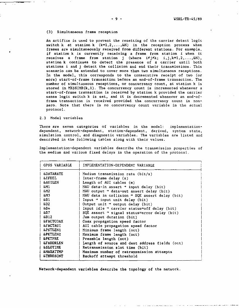
(3) Simultaneous frame reception
An artifice is used to prevent the resetting of the carrier detect logicswitch k at station k (k=l,2,...,&N) in the reception process whenframes are simultaneously received from different stations. For example,if station k is currently receiving a frame from station i when itreceives a frame from station j (where iij~k; i,j,k=1,2,...,&N),station k continues to detect the presence of a carrier until bothstations i and j detect the collision and end their transmissions. Thisscenario can be extended to cover more than two simultaneous receptions.In the model, this corresponds to the consecutive receipt of two (ormore) start-of-frame transaction before an end-of-frame transaction. Thenumber of simultaneous receptions, or concurrency count, at station k isstored in MX$SIMR(k,l). The concurrency count is incremented whenever astart-of-frame transaction is received by station k provided the carriersense logic switch k is set, and it is decremented whenever an end-of-frame transaction is received provided the concurrency count is non-zero. Note that there is no concurrency count variable in the actualprotocol.
2.3 Model variables
There are seven categories of variables in the model: implementation-dependent, network-dependent, station-dependent, derived, system state,simulation control, and diagnostic variables. The variables are listed anddescribed in the following tables along with their values.
Implementation-dependent variables describe the transmission properties ofthe medium and various fixed delays in the operation of the protocol.
GPSS VARIABLE IMPLEMENTATION-DEPENDENT VARIABLE
&DATARATE Medium transmission rate (bit/s)&IFDEL Inter-frame delay (s)&AUILEN Length of AUI cables m)&Ml MAU data-in assert - input delay (bit)&M2 MAU output - data-out assert delay (bit)&M3 MAU data in collision 4 SQE assert delay (bit)&D1 Input - input unit delay (bit)&D2 Output unit output delay (bit)&D4 Input idle carrier status=off delay (bit)&D7 SQE assert + signal status=error delay (bit)&D12 Jam output duration (bit)&FACTCOAX Coax propagation speed factor&FACTAUI AUI cable propagation speed factor&PKTLEN1 Minimum frame length (oct)&PKTLEN2 Maximum frame length (oct)&PKTPRE Preamble length (oct)&FADDRLEN Length of source and dest address fields (oct)&SLOTIME Retransmission slot time (bit)&MAXATTMP Maximum number of retransmission attempts&THRESCNT Backoff attempt threshold
Network-dependent variables describe the topology of the network.

WSRL-TR-45/89 10 -
r rGPSS VARIABLE I NETWORK-DEPENDENT VARIABLEI I
I &N I Number of stations in the networkI ML$PROPDEL(j,k) I Propagation delay (s) from station j to kI &POSN(k) Distance of station k=1,2,...,&N from end of coaxI __ _ _ _ _ _I _ _ _ _ _ _ __ _ _ _ _ _ _ _ _ _ _ _ _
Station-dependent variables describe the properties of the trafficgenerated at each station.
I I
GPSS VARIABLE I STATION-DEPENDENT VARIABLE
I &MAR(k) Mean frame generation rate at stationI ML$PROB(j,k) Probability station j sends frame to station k
Derived variables are functions of protocol, network and station-dependentvariables.
GPSS VARIABLE DERIVED VARIABLE
&Al= &AUILEN/(3.0E8*&FACTAUI) AUI propagation delay (s)&SLOTDEL = &SLOTIME/&DATARATE Retransmission slot delay (s)&MINFMDEL= 8*&PKTLENI/&DATARATE Minimum frame transmission
delay (s)&JAMDEL= &D12/&DATARATE Jam transmission delay (s)&PREAMDEL= 8*&PKTPRE/&DATARATE Preamble transmission delay (s)&MAXDATA= &PKTLEN2-2*&FADDRLEN-6 Maximum data field length (oct)&DATT= &PKTLENl-2*&iADDRLEN-6 Minimum data field length without
pad (oct)&MAXOVRHD= 8+&PKTLENI Maximum overhead (oct)&MINOVRHD= 14+2*&FADDRLEN Minimum overhead (oct)&SGOUTDEL= &Al+(&D2+&DM2/&DATARATE DTE output - MAU data assert
delay (s)&SGDETDEL= &Al+(&M1+&Dl)/&DATARATE Data input LLC detect delay (s)&COLSNDEL= &Al+(&M3+&D7)/&DATARATE Collision LLC detect delay (s)&SGENDDEL= &Al+&D4/&DATARATE End signal- LLC detect delay (s)BV$PAD= 0 if <PH4>S&DATT, else=l Zero if pad not requiredV$FAC= <PH1>+&N Index of dummy facilityV$RX= <PH3>+2*&N Index of receiver facilityV$CTS= <PHI>+2*&N Index of CTS logic switchV$OVERHEAD= (&MAXOVRHD-PH4)* Frame overhead (oct)
BV$PAD+&MINOVRHD*(1-BV$PAD)ML$CUMP(j,k) Cumulative probability of
transmission from station j to k
System state variables describe the dynamic state of the model.

- 11 - WSRL-TR-45/89
GPSS VARIABLE SYSTEM STATE VARIABLE
PBl Frame status (O=head-of-frame, l=end-of-frame)PHI Address of transmitting stationPH2 Address of destination stationPH3 Address of receiving stationPH4 Length of data field in frame (oct)PLI Frame transmission delay (incl preamble) (s)PL2 Frame transfer delay (s)PL3 Backoff delay remaining (s)PL4 Inter-frame delay remaining (s)
I XF$DEV,..,XF$DEV+21 Savevalues used by external random no. generatorsMX$UNOD Array of size &Nx&N used by ext routine &SRANDINIML$MAXBKDEL(k,1) Maximum backoff delay (s) at station'kACl Simulator absolute clock time (s)M1 Transaction transit delay (s)CH(i) Current contents of user-chain iLR(i) =1 if logic switch i reset, else=OLS(i) =i1 if logic switch i set, else=OFNU(i) =1 if facility i not in use, else=O
In order to simplify the description of the model, variables that are notstrictly relevant to the protocol will not be described. These variablesare used in controlling the simulation (eg model warm-up time, run time,sample intervals, random number streams etc) and in the measurement ofperformance.
2.4 Simulation results
Two simulation experiments were conducted. The first experiment wasdesigned to compare the output from the simulation model, referred to asModel "A", with data from an analytic model. This activity validated theoperation of the model. In the second experiment, the protocol delays thatwere assumed to be zero in the analysis of Model "A" (viz &M, &M2, &M3,&D1, &D2, &D4, &D7, and &D12) were assigned finite values-to assess theireffect upon the performance of the protocol. This simulation model isreferred to as Model "B".
Several analytical models of Ethernet have been reported in theliterature(refs.5,23,28,35). Lam's semi-Markov model is considered to beone of the most accurate analytic representations of the Ethernet MACprotocol(ref.9). The analytic formulae are expressed in convenient form inAppendix II.
Listed below are the parameter values assumed in Model "A".
(1) Single segment LAN topology
(2) Network of 5 stations equally spaced over a distance of 2 km
(3) Unit capacity buffer at each station
(4) 10 M bit/s data transmission rate
(5) Identical, independent Poisson-distributed frame generation rates
(6) 300 oct fixed length frames (irfcluding 26 oct overhead)
(7) Propagation delay linearly proportional to distance (5 ps/km)

WSRL-TR-45/89 - 12 -
(8) Inter-frame gap equal to the maximum propagation delay (10 Us)
(9) Standard backoff attempt threshold (10)
(10) Standard re-transmission attempt limit (16)
(11) Other delays neglected (including jam)
Law and Carson's sequential analysis method(ref.25) was employed toestimate the steady-state value of the transfer delay. For each run of themodel several hundred initial observations were discarded to avoid biasingthe results. Kimbler's algorithm(ref.20) was used to determine the numberof observations to be discarded (viz the model "warm-up" period). Theresults are depicted in figure 9 by a graph of the 95% confidence intervalof the normalised mean transfer delay verses normalised mean throughput.The value of the normalised maximum mean throughput asymptote shown isderived in Appendix II.
The simulated and analytic mean delays are generally in excellent agreementsince most of the confidence intervals include the analytic values. Thisresult confirms that the error in approximating normal (un-slotted)operation by a discrete imbedded Markov chain model is minimal.
In figure 10, the probability of zero channel assignment delay is plottedagainst normalised mean throughput. The agreement with analysis is againexcellent despite the fact that the simulation model, which replicates theoperation of the backoff algorithm in the protocol, does not satisfy theanalytic assumption that the probability of a successful transmissionwithin any one of the slots subsequent to a collision is constant (equal to1/e=0.368). Discrepancies are attributed mainly to sampling error but thiscould not be verified because interval estimates were not available fromthe simulation.
Other results obtained from the simulation model include the (unit) bufferoverflow probability (viz probability that a frame is rejected because ofinsufficient buffer capacity), and the mean transmitter and receiverutilisations. Figure 11 shows that the buffer overflow probability isapproximately logarithmically dependent on the normalised mean throughputover the range of throughputs considered. This is emphasised by a line ofregression which is fitted to the data and constrained to pass through thecoordinate whose normalised mean throughput is the theoretical maximum andwhose probability value is unity.
The transmitter and receiver utilisations represent the fractions of timethat the transmitter and receiver facilities (1,...,&N and l+2*&N,...,3*&Nrespectively) are busy transmitting (complete and partial) frames onto, andreceiving those frames from, the transmission medium. Since the specifiedframe arrival rates at the MAC sublayer of each station are identicallydistributed, the utilisations are taken as weighted averages of theindividual station utilisations in order to improve statistical accuracy.The linear dependence of the utilisations on mean throughput is illustratedin Figure 12. The lines of regression fitted to the data are constrained topass through zero utilisation at zero throughput. A useful check toconfirm correct model operation is to compare the slopes of the lines ofregression with the theoretical values. The weighted transmitterutilisation should be equal to E[X]/100, the ratio of the aggregate meanframe arrival rate (X) to the maximum throughput rate (l/(E[T p]+T )) (see
Appendix II for symbol definitions). The slope of the regression line forthe transmitter should therefore be 0.008214. The measured slope is0.00803. The ratio of the slopes of the lines of regression should be

- 13 - WSRL-TR-45/89
(&N-1)=4, the theoretical ratio of the transmitter utilisation to thereceiver utilisation for a network of &N=5 stations. The reason for theratio being one less than the number of stations is that transmittingstations are inhibited from receiving their own frames. The measured ratioof the slopes of the regression lines is 3.91. Both measurements aresufficiently close to the corresponding theoretical values to confirmproper model operation.
In the second part of the experiment, the protocol delays previouslyassumed to be zero were replaced by the maximum values specified in theANSI 802.3 standard (viz &MI=6, &M2=3, &M3=17, &D1=18, &D2=3, &D4=4, &D7=3,and &D12=32 bits). In addition, the inter-frame delay, &IFDEL, wasslightly reduced from the previous value of 10 Us to the "10BASES"implementation value of 9.6 Us. Pilot runs were conducted for Model "B"and also analysed using Kimbler's algorithm and Law and Carson's sequentialprocedure. The difference in performance between the two protocols, one
with zero delays and the other with maximal delays, was then measured atseveral throughput values by comparing the outputs from Model "A" and Model"B". Since at each throughput level the point estimator of the meantransfer delay was less for Model "A" than Model "B", the paired sample,one-tailed Stud t "t" test was employed to ascertain the statistical levelof significance of the differences.
Pairs of fixed-length runs were made using common random variates(ref.26,pp 319 to 322) to reduce the variance of the population differenceestimator. The number of observations discarded in the warm-up period andthe number of observations required for steady-state analysis were chosenat each throughput level to be the maximum of the corresponding valuesobtained from Model "A" validation and the pilot run of Model "B". One pairof runs was made at each throughput level. In each pair of runs, the firstrun was of Model "A", and the second was of Model "B". The pairing ofobservations was accomplished by assigning a serial number to a transactionparameter in each frame transaction as it entered the model. Upon leavingthe model at the point of successful reception at the destination station,the calculated transfer delay was stored in an element of a 2-row matrixindexed by the transaction serial number. One row of the matrix containedobservations from the first run and the other row contained observationsfrom the second run. The averages of the paired differences required forstatistical analysis were obtained by subtracting the paired observations(viz the elements in each column of the matrix), grouping them seriallyinto 40 equal-sized batches (neglecting any observations left over), andcomputing the batch means. Note that only paired observations were used.Unpaired observations, indicated by zero-valued elements in the observationmatrix, were ignored. Batching was employed to minimise the effect ofserial correlation inherent in the observed differences.
The results of the "t" test are tabled below. The estimated values of thenormalised mean transfer delay, E[DA] for Model "A" and E[DB] for Model
"B", are shown as functions of both the mean aggregate frame generationrate (X), and the normalised mean throughputs, E[XA] and E[XB]. The latter
are dependent on PbA(k) and PbB(X), the load-dependent buffer overflow
probabilities for the respective models. In addition, the statisticalconfidence levels are shown which represent the probability of E[DA]<E[DBI.

WSRL-TR-45/89 - 14 -
Mean frame I Normalised Mean Normalised Mean I Probgeneration Throughput (%) Transfer Delay (E[DA)]<E[DB])
rate
X(s') E[XA] E[XB] E[DA) E[DB]
500 12.0 12.0 1.096 1.100 >0.995875 21.0 21.0 1.183 1.191 0.951500 35.8 35.8 1.404 1.417 0.952000 47.2 47.3 1.674 1.781 >0.995
1 2500 1 56.9 J 57.3 1 2.242 1 2.455 1 >0.9953000 63.5 64.9 3.086 3.534 >0.953500 67.4 69.1 4.164 4.535 >0.95
The results indicate that the mean transfer delay for Model "B" has a veryhigh probability of being greater than that of Model "A". The relativedifference between the normalised transfer delays increases monotonicallywith respect to Model "A" delays, from about 0.3% at 12.0% normalised meanthroughput to 14.5% at 63..5% normalised mean throughput, but drops to 8.9%at the highest throughput level. Whether or not the inconsistency in thistrend is due to a statistical fluctuation or is real cannot be ascertainedwithout significantly increasing the sample size. This action was notundertaken due to the considerable expense involved.
The 95% confidence intervals for the normalised mean transfer delay aredepicted in figure 9 as a function of the normalised mean throughput tofacilitate the visual comparison of the performance predicted by Models "A"and "B" and the analytic model.
3. TOKEN RING SIMULATION MODEL
ANSI 802.5 is a token-passing protocol designed to transmit data in a closedring network as shown in figure 13. The relationship of the Token Ringprotocols to the OSI Reference Model is depicted in figure 14. The principlesof operation of the MAC protocol relevant to the simulation model aredescribed in Appendix III.
In Section 3.1 the structure of the simulation model is described with the aidof GPSS block diagrams. As in the case of the Ethernet simulation model, theToken Ring simulation model does not take account of network initialisation,error recovery and other procedures not directly involved in frametransmission. Neither does it allow for the corruption of frames duringtransmission over the medium. The structure of the model is much simpler thanthe Ethernet model, reflecting the fact that it is only an approximation ofthe protocol. Special techniques are described in Section 3.2 to model thetoken holding timer and to improve the run-time efficiency of the model. Thevariables of the simulation model are described in Section 3.3.
Despite the approximations, the model is very flexible. Any number of stationsgreater than one may be specified, the stations may be positioned anywhere onthe ring, and different frame generation rate and frame length distributionsmay be specified. The major limitation is that only one level of framepriority is allowed because the states and transitions in the MAC protocolresponsible for servicing multiple priorities are not modelled. Modificationscan be easily made to include priorities, but this was not done since, unlikeEthernet, there was no customer requirement for an exact model of the TokenRing protocol.

- 15 - WSRL-TR-45/89
Methods similar to those described in Section 2 for Ethernet were employed inanalysing simulation output. Analytic results were also used to validate thesimulation model since a Token Ring test bed facility was unavailable. Theresults obtained during model validation are presented in Section 3.4.
3.1 Model structure
The simulation model mimics the frame generation process in the LLCsublayer and the frame delivery process in the MAC sublayer. Only MACstates 0 to 3(ref.13) are modelled. To avoid the repication of GPSS blockswhen modelling the processes in each station, structural folding isemployed as described in Section 2.1.
3.1.1 Frame generation
The first four blocks in the frame generation process, depicted infigure 15, are identical to those employed in the Ethernet model (seeSection 2.1.1). The mean frame generation rate at station k isspecified in ML$STAT(k,3). The blocks generate the sequences of frametransactions and assign a transmitting station address to eachtransaction parameter PHI.
A random transmission duration is assigned to PLl. It is computed bysumming an exponentially-distributed data field length whose mean isspecified in ML$STAT(PHI,4) to the frame overhead, &OVRHEAD, anddividing the resultant frame length (multiplied by eight to convertoctets to bits) by the data transmission rate, &DRATE. The value of PLlis then tested to see whether it is less than the maximum token holdingtime, &THTMAX. If it is not, the transaction returns to the ASSIGN blockat address GENi to enable a new value to be assigned to PLi. If this isnot done, a long frame would never be serviced since there would beinsufficient time available for a station to transmit it. Furthermore,because frames are buffered in first-in first-out (FIFO) order, stationswould be prevented from retaining the token which would eventually causethe model to shut down.
The transaction is then marked with its generation time, which issubsequently used to compute the frame transfer delay, and it isdeposited in the station's buffer (user-chain <PHI>). Notice that priorto entering the user-chain, frame transactions pass through a QUEUEblock and a LOGIC block which are part of a special mechanism, describedin Section 3.2, designed to improve the run-time efficiency of themodel.
3.1.2 Frame delivery
The frame delivery process, illustrated in figure 16, is responsible fortransmitting frames from station to station and controlling the order inwhich stations transmit. Control is exerted by passing a (single)permission token around the ring. A station holding frames in its bufferis only given access to the transmission medium when it captures thetoken. The frames and the token are represented in the model bytransactions.
A token transaction is generated at time zero and waits at a GATE blockpending the arrival of a frame. This block is used in an artifice toimprove the run-time efficiency of the model and is described inSection 3.2. Ignoring the effect of the GATE block for the moment, theaddress of the next station to be visited by the token is assigned toparameter PHI. The address is efficiently computed by modulo division(using the GPSS arithmetic operator "@"). Initially <PHI> is zero. The
WSRL-TR-45/89 - 16 -
next station address is equal to <PHl>+l if <PHI> < &N, or 1 if <PH>=&N(viz (<PHI> mod &N)+l). The token transaction then experiences a delayin an ADVANCE block equal to the station latency, MLSSTAT(PH1,2), whichis the sum of the minimum token holding time, &THTMIN, and thepropagation delay between the stations (equal to the distance betweenthe stations, ML$STAT(PH1,1), divided by the propagation speed).
Upon arrival of the token at a station, the station's token holdingtimer is reset. In the model the reset time is stored in XL$THT andinitialised to the simulator clock time, Cl. A TEST block at addressTOK1 checks whether the station's buffer (viz user-chain <PHl>) isempty. If it is, the token transaction returns to the GATE block ataddress TOKO, where it is passed onto the following station. Otherwise,the frame transaction is removed from the user-chain by an UNLINK blockand sent to block address TOK2. A frame transaction is uncoupled fromthe user-chain in FIFO order by the token transaction, and the tokentransaction is deleted.
Before the uncoupled frame transaction is processed, the amount of timeavailable to the station to transmit the frame is compared at a TESTblock with the time required to transmit the frame (which is stored intransaction parameter PLl). If there is insufficient time available totransmit, the token holding flag is set (viz the value of the booleanvariable BV$THTXPRD is set to unity), so that the transaction is routedto a SPLIT block and returned to user-chain <PHl> where it is positionedin front of the other transactions present. This is achieved byspecifying last-in first-out (LIFO) order in the LINK block andguarantees that the transaction will the first one uncoupled when thetoken transaction subsequently returns to the station. The daughtertransaction from the SPLIT block then becomes the new token transactionand is sent to block address TOKO so that it can be passed to the nextstation.
If there is sufficient time to transmit the uncoupled frame transaction,the frame transaction is delayed in an ADVANCE block for the fulltransmission period. It then passes through a series of blocks whichform part of a mechanism for reducing the run time of the model beforebeing routed to the TEST block at address TOKI (see Section 3.2). Ifthere is another frame transaction in user-chain <PHl>. awaitingtransmission, it then proceeds to uncouple the frame transaction whichhas been waiting the longest and the transmission cycle, previouslydescribed, recommences. Otherwise, the transaction becomes a new tokentransaction and is sent to the GATE block at address TOKO to be passedonto the next station.
3.2 Model artifices
Special techniques are employed to model the token holding timer at eachstation and to improve the run-time efficiency of the model. The GPSSblocks and variables associated with these mechanisms have no equivalentsin the protocol itself.
(1) Token holding timer
The token holding timer in each station is implemented by a savevalue,XL$THT. Only one savevalue is required because only one station at atime ever needs to interrogate the timer. The savevalue is initialisedto the simulator clock time, Cl, when the timer is reset. The tokenholding time remaining is computed by the variableV$THTREHMXL$THT+&THTMAX-Cl, where &THTMAX is the maximum token holdingtime.

- 17 - WSRL-TR-45/89
(2) Token activity monitor
The token activity monitor is a mechanism used to stop the continuouscirculation of the token transaction in the model when the ring is idle(viz no frames on the ring and no station with a frame to transmit).The monitor greatly improves the run-time efficiency of the model at lowframe generation rates.
Several blocks are included in the model to sense ring idleness and tostop and restart the motion of the token transaction. In the framegeneration process, a QUEUE block is used to measure the aggregate queuelength thereby avoiding the complexity of having to sum the individualstation buffer sizes, viz CH(1)+CH(2)+...+CH(&N). Whenever a new frameis generated at a station the aggregate queue length, Q(QAGG), isautomatically incremented, and a logic switch (LOOP) is set to denotethe presence of a new frame.
In the frame delivery process, the GATE block at address TOKO preventsthe circulation of the token transaction on the simulated ring if theLOOP logic switch is reset. Four other blocks are also included in thisprocess. On leaving the ADVANCE block responsible for imparting thetransmission delay, a frame transaction enters a DEPART block whichdecrements the aggregate queue length Q(QAGG). If the queue length isthen zero, logic switch LOOP is reset and the transaction is routed tothe GATE block at address TOKO, via the TEST block at address TOKl, andbecomes the new token transaction. This transaction is then stopped atthe GATE block pending the generation of a frame. However, if the queuelength is non-zero, the frame transaction returns to the TEST block ataddress TOKl without resetting logic switch LOOP and uncouples the nextframe transaction from user-chain <PHl>.
3.3 Model variables
The seven categories of model variables defined in Section 2.3, exist inthe Token Ring model. For the same reasons stated in that section, thesimulation control and performance variables will not be described.
I GPSS VARIABLE I IMPLEMENTATION-DEPENDENT VARIABLE
& &DRATE Medium transmission rate (bit/s)I &OVRHD I Frame overhead (oct)I &THTMIN I Minimum token holding time (s)I &THTMAX I Maximum token holding time (s)&FACTOR I Propagation speed factor
I __ _ __ _ _ i _ _ _ _ _ _ _ _ _ __ _ _ _ _ _ _ _ _ _
I GPSS VARIABLE I NETWORK-DEPENDENT VARIABLE
I &N Number of stations in the networkI ML$STAT(k,l) Distance (m) between stations k and (k mod &N)+lL _ _ __ _ _ I __ _ _ _ _ _ _ _ _ _ __ _ _ _ _ _ _ _ _
I GPSS VARIABLE I STATION-DEPENDENT VARIABLE
I ML$STAT(k,3) I Mean frame generation rate at station k (s,')I ML$STAT(k,4) I Mean length of frames (excluding overheads)
I transmitted by station k (oct)

WSRL-TR-45/89 - 18 -
I GPSS VARIABLE DERIVED VARIABLE
I ML$STAT(k,2)=(&THTMIN+ML$STAT(k,1)/I (&FACTOR*3.0E8) Station latency (s)V$THTREM=XL$THT+&THTMAX-Cl Token holding time remaining(s)
I BV$THTXPRD=O if V$THTREM<<PL>, Token holding flagI else=l
GPSS VARIABLE SYSTEM STATE VARIABLE
PHI Address of transmitting stationPLI Frame transmission delay (incl preamble) (s)XL$THT Time token holding timer is reset (s)Cl Simulator relative clock time (s)CH(i) Current contents of user-chain iQ(QAGG) Current length of aggregate queue, QAGGMl Transaction mark-time (s)XF$DEV,XF$DEV+I Savevalues used by external random no. generators
3.4 Simulation results
The correct operation of the simulation model was confirmed by comparingthe mean frame transfer delay derived from the simulation with the meantransfer delay obtained from Bux's analytic formula in Appendix IV.
Ik, order to effect a proper comparison, the following assumptions were
made.
(1) Infinite buffer capacity at each station
(2) 1 M bit/s data rate
(3) Network of 50 stations equally spaced over a 2000 m length ring
(4) Identical, independent Poisson-distributed frame generation rates
(5) Length of data field in frames exponentially-distributed with meanof 125 oct
(6) 3 oct fixed frame overhead
(7) Medium propagation speed factor=0.66
(8) 1 Us minimum token holding time
(9) 1 s maximum token holding time (chosen to ensure that at thehighest throughput levels a station does not release the token beforeits buffer is fully depleted)
The steady-state mean frame transfer delay was computed in identicalfashion to the Ethernet model, using Law and Carson's sequential method ofBatch Means following a warm-up period determined by Kimbler's algorithm.
Variance reduction was effected using the method of AntitheticVariates(ref.l, chap.2). Two runs were employed and the paired observationsaveraged to produce a single sequence of data for analysis. Varioustreatments were examined to determine which was the most effective in

- 19 - WSRL-TR-45/89
reducing the variance of the data. Greater variance reduction was achievedusing antithetic variates for both frame inter-arrival times and framelengths (the only exogenous random variables in the model) compared tousing antithetic variates for one variable and independent variates for theother.
To obtain a 95% confidence interval with 5% relative precision atthroughput levels less than 50%, about the same amount of computationaleffort was expended on the two antithetic runs as on a single run. Howeverat higher throughputs, antithetic variates were superior. For example, atthe 80% throughput level, a total of 102400 observations (viz 51200observations in each run) were needed using antithetic variates compared to204800 observations for a single run.
Figure 17 illustrates the dependence of the normalised mean frame transferdelay on the normalised mean throughput. The 95% confidence intervals ofthe delay obtained by simulation overlap the data values generated by theanalytic model. The mean delay was found to be insensitive to the maximumtoken holding time provided it was greater than the nominal 10 ms value.
4. EXTERNAL PROCEDURES USED IN SIMULATION
GPSS/H is limited in its ability to perform mathematical operations (onlyaddition, subtraction, multiplication, division and modulo division arepossible) and to generate random numbers from continuous distributions.However, it does have a very efficient and easy to use high-level languageinterface which permits Fortran, C, and Pascal procedures to be called to dothese tasks.
Several Fortran procedures were called by the Ethernet and Token Ringsimulation models to perform mathematical operations and to generate randomnumbers. The mathematical routines are not described because they were onlyused in post-run data analysis. The procedures called to generate randomnumbers are described below and are based on an external uniform (0,1) randomnumber generator(ref.30). Note the GPSS/H convention of referring to anexternal procedure named "XXXX" by an external ampervariable "&XXXX". Inaddition, if the procedure is a Fortran function, the first letter of its nameidentifies the type of function (viz I-N integer; A-H and O-Z real).
&SRANDEF(M,IV)
This subroutine must be called to initialise the integer vector IV priorto calling any of the external random number generators (viz &REXPON,&RUNIF and &IDEST). M>0 (integer) specifies the number of random numberstreams to be initialised. It initialises each stream with a common seedvalue of 266301881 (similar to the GPSS/H built-in generators). Theoffset of each stream j (j=1,2,.... ,M) is internally generated by theroutine according to the formula 1000000*j. (The same formula is usedby GPSS/H for default streams).
&REXPON(N,IV,A)
Generates an exponentially distributed real number with mean andstandard deviation A>0 (real). N is the (integer) stream number and IVis an integer vector (see routine &SRANDEF).
&RUNIF(N,IV,A,B)
Generates a uniformly distributed real number in the open interval (AB)
WSRL-TR-45/89 - 20 -
where A and B are real. The mean and variance are (A+B)/2 and(B-A)*(B-A)/12 respectively. N is the (integer) stream number and IV isan integer vector (see routine &SRANDEF).
&SDESTINI(M,RP,RC,ID)
This routine is used to initialise the real array RC and the integerarray ID prior to calling the routine &IDEST. It computes thecumulative routing probabilities (viz the elements of RC) from theprobability matrix RP. Each (real) element of RP must be specified.RP(i,j) represents the probability of a message being sent by node i(i=l,2, .. ,M) to node j (j=l,2,...,M) where M is the (integer) number ofnetwork nodes. The row elements of RP must lie in the closed interval
[0,1] and sum to 1.0 ±10-'. (It is permissible for diagonal elements ofRP to be non-zero.) The routine also computes the elements of ID, amatrix of node addresses ordered such that if i>j, the probability ofnode ID(k,i) being the recipient of a message from node k#i,j is greaterthan, or equal to, the probability of node ID(k,j) being the recipient.
&IDEST(N,IV,L,M,RC,ID)
Generates the (integer) number of the node to which a message will berandomly directed in a network of M (integer) nodes from the sendingnode L (integer) where L=1,2,...,M. RC is a real matrix and ID is aninteger matrix (see routine &SDESTINI). N is the (integer) streamnumber and IV is an integer vector (see routine &SRANDEF).
5. MODEL VERIFICATION
Confidence in a model is ultimately established by comparing model predictionswith the actual data obtained from the system under investigation. But first,the operation of the model must be scrutinised to eliminate programming andconceptual isation errors. All of the possible events, logical conditions and
transaction paths in the model, corresponding to the true states andtransitions in system, should be exercised to ascertain correct operation.
The interactive debugging facility of GPSS/H is particularly useful forverifying the operation of a model. Model execution can be interrupted at anystage to enable the current values of state variables (eg transactionparameters, logical conditions, statistics associated with static entities,etc) to be observed. Single stepping, and stopping at user-specified break-points (viz blocks) and pre-defined trap conditions (viz model states) aresupported. In addition, the current state of the model may be checkpointed(saved) and restored at a later time after further execution of the model.Unless a trap or break-point is encountered, the model executes untilcompletion or until a fatal run-time error occurs. When tracing a fatal run-time error, the state of the model must be saved periodically to avoid havingto re-run it from the start. The checkpoint/restore facility can saveconsiderable time and effort when run lengths are large.
Most features of the interactive debugger were utilised in verifying theoperation of the Ethernet and Token Ring models. The debugger is efficient andthe output is presented in a format similar to the standard printed output andis easy to read provided it is directed to a 132 column visual display.
- 21 - WSRL-TR-45/89
6. SIMULATION OUTPUT ANALYSIS
In Section 6.1 the problems associated with analysing simulation output dataare briefly discussed and several methods of achieving variance reduction inLAN protocol models are described. The measured execution times of theEthernet and Token Ring models are presented in Section 6.2.
6.1 Bias and variance reduction
The accuracy of the performance estimates derived from a simulation modelis critically dependent upon the length of the simulation run. Practicalconsiderations of cost and time often prevail so that runs are shorter thandesired. The challenge in analysing simulation output is to concurrentlyminimise the statistical bias due to model start up, and the variance ofmean estimators, given a limited number of samples and a significant degreeof serial correlation in the samples.
Provided the underlying distribution of the output random variables isnormal and stationary, and the variables are independent, the statisticalaccuracy of an estimator of a mean value, measured by the relativeprecision of its confidence interval, is a simple function of samplevariance. A sample variance can be easily obtained from GPSS/H defaultstatistics or by using a TABULATE block and an associated TABE statement.However, simulation output variables seldom satisfy these stipulations andstandard GPSS/H statistics, particularly sample variances, consequentlyprovide little assistance in estimating the accuracy of mean estimators.
The problem of obtaining steady-state measures of performance is compoundedby the need to ascertain how long a simulation model must be warmed up toachieve steady-state conditions. The duration of the warm-up period, or the"initial transient" as it is sometimes called, depends upon the choice ofinitial conditions. Unless the samples acquired during this period arediscarded, the steady-state statistics will be biased. Several heuristicprocedures are available to estimate the number of samples that should bediscarded(refs.7,11,18,20,25,30,32). Most of the procedures have beentested on models of M/M/l queues which are amenable to mathematicalanalysis and considered difficult to analyse since they exhibit a verygradual transition from transient to steady-state behaviour. Whether theseprocedures are as effective in more complex simulation models is a topic ofcurrent research.
In the analysis of the Ethernet and Token Ring models, Kimbler's doubleexponential tracking filter(ref.20) was employed because it has been shownto discard fewer samples and is computationally more efficient compared toother methods. It also performs as well as the more complex methods. Atrend toward shorter warm-up periods at higher throughput levels wasobserved in all of the models. Warm-up periods varied between 0.05 s and1.76 s for Ethernet Model "A", and between 0.16 s and 5.4 s for the TokenRing model.
An effective method of reducing the sample variance, and reducing the runlengths required for a given statistical accuracy, is to use a variancereduction technique. Several techniques(refs.l,17,26) are available foranalysing single systems and for comparing several systems. Amongst theeasiest methods to use for single systems are Antithetic Variates andConcomitant Variates. Both methods work best if the input random variablesare highly correlated with the variables under analysis. Selecting inputrandom variables is usually very difficult without first conducting pilotruns, especially when there are many from which to choose. Poor choices ofvariables will produce little variance reduction or may indeed lead to anincrease in variance. The key to success in using both of these techniques

WSRL-TR,-4./89 - 22 -
is to properly synchronise the input variates in repeated runs. This isachieved by generating identical random number streams(ref.30). Despitethat fact that in some models only partial synchronisation can be achieved,the amount of variance reduction may still justify the programming effort.
The method of Common Random Numbers is employed when comparing theperformance of several similar systems. In the case of only two systems,runs are made in pairs using identical streams of random numbers. The two-sample Student "t" test is then applied on the paired output variates. Thecorrelation between the variates is usually very effective in reducing thevariance of the estimator of the mean difference between performancemeasures compared to using independent random number streams. Additionalvariance reduction techniques are rarely used concurrently with CommonRandom Numbers due to programming difficulties and because the combinationof techniques is frequently ineffectual.
The method of Common Random Numbers was used to investigate the effect ofvarying Ethernet parameters, whilst Antithetic Variates was used inanalysing the performance of the Token Ring model.
Other variance reduction methods assessed to be of potential in LANprotocol modelling include External Control Variates(ref.34), ConditionalExpectations(ref.19) and Indirect Estimation(ref.26, pp 361-363 and ref.8).Whether these methods are employable depends entirely upon the individualcharacter of the model. They are generally limited to Markovian queuingmodels.
An alternative, albeit indirect, approach to achieving variance reduction,is to replace computationally intensive portions of a simulation model byanalytic procedures. For example, instead of simulating a process delay bypassing a GPSS transaction through a sub-model (viz a series of GPSSblocks), a transaction may be delayed by a single ADVANCE block whose(deterministic or random) delay value is computed numerically by anexternal procedure. The values of the independent variables in the formulaare copied from the global and local variables in the model when thetransaction enters the ADVANCE block. Such hybrid simulation techniques areanalogous to analytic network "decomposition" techniques (eg Norton'stheorem in electrical circuit theory) and are only applicable if thesubstituted portions of a model are "weakly" interactive with each otherand the remaining (viz simulated) portion of the model(ref.4). Hybridmodels of general queuing networks(ref.19) and computer communicationnetworks (refs.3,33) are in wide use and significant improvements incomputational efficiency have been claimed for them. Hybrid models holdconsiderable promise for LAN protocol modelling(ref.24).
The serial correlation present in most simulation output variables leads tothe under-estimation of variances and confidence interval widths whenclassical statistical methods are used. Better methods are based on theanalysis of a staneardised time series(ref.31), the spectral estimation ofof a time series(ref.6) and modified classical methods(ref.27). Thesimplest modified classical method, that of Batch Means, seeks to reducethe effects of serial correlation by grouping, or "batching", the data sothat the batch means are less correlated than the individual sample values.Law and Carson's sequential batch method(ref.25) was used in computingconfidence intervals for the mean frame transfer delay times derived fromthe Ethernet and Token Ring models.
6.2 Model execution times
The Zthernet and Token Ring simulation models are expensive to run.Average execution times per GPSS/H block, measured on a dedicated (viz

- 23 - WSRL-TR-45/89
single user) DEC-VAX 8200 computer running the VMS 5.1 operating system,varied between 100 Us and 114 Us for the Token Ring model, and between149 Vs and 192 Us for the Ethernet model. The differences are primarily dueto the different types of blocks used and amount of processing involved inthe management of transactions. The Ethernet model, for example, has manymore transactions and transaction parameters which impose greater overhead.
More CPU time was needed on the host computer to execute the same intervalof simulated time at higher throughputs because the number of activetransactions in the models increases with the simulated load level. The CPUtimes to execute each model were measured. The results, tabled below,include a slight amount of overhead for the collection and analysis ofobservations and apply to simulation without the use of variance reductiontechniques.
ETHERNET MODEL
Normalised mean Simulated time CPU time Executionthroughput (%) (s) (s) I time ratio
12 3.3 44 I 1321 1.4 34 I 2436 2.7 120 4447 3.6 250 6957 10.7 1095 I 10264 9.7 1403 14567 18.0 3323 185
TOKEN RING MODEL
Normalised mean Simulated time CPU time Executionthroughput ( ) (s) (s) time ratio
10 261 440 1.6820 o 5 210 3.2330 43 182 4.2340 32 180 5.6350 51 334 6.5560 43 321 7.4770 293 2146 7.3280 256 2121 8.2990 455 3104 6.82
Note the difference in the execution time ratios between the two models.The execution time ratio is the ratio of the CPU time to the simulated timeinterval. The figures indicate that the Token Ring model is considerablymore efficient than the Ethernet model and reflect the additionalcomplexity and transaction activity in the Ethernet model.
The execution time ratio for the Ethernet model increases very rapidly, dueto the increased frequency of collisions, as the normalised mean throughputapproaches the theoretical saturation limit of 82.141. This contrasts withthe Token Ring model which demonstrates more linear behaviour up to thesaturation limit of 1001. The execution efficiency of the Token Ring modelwas greatly enhanced at low throughputs by the token activity monitormechanism described in Section 3.2.

WSRL-TR-45/89 - 24 -
7. DISCUSSION AND CONCLUSIONS
Two LAN protocol simulation models, an Ethernet (ANSI 002.3) and a Token Ring(ANSI 802.5) model, were built to assess the potential of the GPSS/Hsimulation language for modelling the performance of LAN protocols. TheEthernet and Token Ring protocols were selected because they are relevant tomilitary LAN applications and because well-documented analytic models existwhich can be used to validate simulation models.
It was found that the process interaction approach of GPSS/H leads to anatural representation of frames and tokens as dynamic entities (transactions)which incur delays as they move through static elements (blocks) in the model.The GPSS blocks represent incremental units of processing associated with thetransmission and reception of the frames and tokens. For example, the commonlyused SEIZE and ADVANCE blocks, and conditional GATE and TEST blocks imposetransaction delays; PREEMPT blocks and unconditional GATE and TEST blocksmodify processing sequences; LOGIC, SAVEVALUE, MSAVEVELAUE and BLET blocksalter the global state of the model; ASSIGN blocks change the values ofparameters associated with individual transactions; GENERATE and SPLIT blocksinject transactions into a model; and TERMINATE blocks remove transactionsfrom a model. There are many additional block types that have not beenmentioned above.
In the Ethernet model, separate transactions are used to denote the head andthe end of each frame sent to each station, whereas in the Token Ring model asingle transaction is used to model a frame and a token circulating around thering. Some of the parameters associated with these transactions include framelength, and source and destination station addresses.
State diagrams of the LAN protocols were found to be very useful aids indesigning simulation models. The states and transitions associated with theerror-free operation of the protocols were mapped into GPSS block diagrams,representing the logical conditions, transactions paths, and synchronisationof events in the models, prior to program coding.
Programming artifices were employed to model timers. In the Ethernet model adummy facility is used to permit timer transactions to be removed from theGPSS future events chain prior to time-out because no direct method exists inthe language for removing a transaction from this chain. In the Token Ringmodel, a separate timer transaction is not employed to model the token holdingtimer because no change of state results from the expiry of the timer.Instead, the timer is implemented by a global variable (a savevalue) which isinitialised to the simulated time at the receipt of a token and subsequentlyadjusted at the start of each frame transmission when the amount of timeremaining prior to timer expiry is computed.
The only criticisms of GPSS/H are its inability to accurately sample randomnumbers having continuous distributions and its inability to performmathematical operations other than basic arithmetic. These problems are beingaddressed by the manufacturer. Fortunately, GPSS/H includes a simple andefficient mechanism for calling external routines to accomplish these tasks sothat these omissions only cause inconvenience and are not major deficienciesin the language.
The GPSS/H interactive debugging facility was found to be an excellent toolfor verifying correct model operation, and locating and identifying the causesof run-time errors.
Difficulties associated with the statistical analysis of non-normal andserially correlated simulation output data were outlined. The implications arethat standard GPSS/H statistics, particularly sample variances, are of little

- 25 - WSRL-TR-45/89
assistance in estimating the accuracy of steady-state measures of performance.In addition, bias may be introduced unless samples acquired during a model'sinitial transient, or "warm-up" period, are excluded from the analysis.Methods of improving the efficiency of statistical estimators, includingvariance reduction techniques and hybrid simulation, were described.
In both the Ethernet and Token Ring models, Kimbler's algorithm was used toestimate the number of samples to be discarded during the warm-up period, andLaw and Carson's sequential method of Batch Means was employed to determineconfidence intervals for steady-state mean values. Two variance reductiontechniques were employed. The Common Random Variates technique was used forcomparing two models of Ethernet, and Antithetic Variates for analysing theToken Ring model.
Experience gained from simulating the steady-state operation of the Ethernetand Token Ring MAC protocols suggests that GPSS/H is a very flexible, user-friendly and efficient language. GPSS/H should be equally suited to modellingother LAN protocols.
8. ACKNOWLEDGEMENTS
The author wishes to acknowledge with gratitude the encouragement andscholarly advice provided by Mr J.G. Schapel (WSRL) and Dr D.M. Panton (MathsDept, SA Institute of Technology), and the assistance of Messrs M.J. Colemanand R. Currie (WSRL) in the preparation of the diagrams for this report.

WSRL-TR-45/89 - 26 -
ABBREVIATIONS
ANSI American National Standards InstituteAUI Access Unit Interfacec.i. confidence intervalCSMA/CD Collision Sense Multiple Access (with) Collision DetectionCTS clear to sendDEC Digital Equipment CorporationDTE Data Terminal EquipmentFDDI Fiber Distributed Data InterfaceFIFO first in, first outGPSS General Purpose Simulation SystemIBM International Business Machines Corporationkm kilometreLAN Local Area NetworkLIFO last in, first outLLC Logical Link Controlm metremod moduloms milli-secondns nano-secondMAC Media Access ControlMAU Medium Attachment UnitM bit/s mega-bits/ secondoct octetOSI Open Systems InterconnectionSQE Signal Quality ErrorTHT Token Holding Time(r)TRR Return to repeat (state) TimerXAC transaction11s micro-second

-27- WSRL-TR-45/89
REFERENCES
No. Author Title
1 Bratley, P. "A Guide to Simulation".Fox, B.L. and 2nd Ed. Springer-Verlag New York NY,Schrage, L.E. 1987
2 Bux, W. "Local Area Subnetworks: A PerformanceComparison".Advances in Local Area Networks. Ed.Kuemmerle, K., Limb, J.O., and Tobagi,F.A. pp 363-382.IEEE Press New York NY., 1987
3 Chiarowongse, J., "A Simulation Model for LargePark, J.T., Interconnected Local Area Networks bySrinivasan, M.M., and Decomposition Techniques".Teorey, J.J. IEEE Proc. Simulation of Computer
Networks, pp 64-72, 1987
4 Courtois, P. "Decomposability, Instabilities, andSaturation in MultiprogrammingSystems".Comms. ACM. Vol. 18, No. 7, pp 371-377,July 1975
5 Fapojuwo, A.O., "An Iterative Approximation forChan, W.C. and Modelling Buffered CSMA-CD LANs".Irvine-Halliday, D. J. Electrical and Electronic
Engineering IE Aust & IREE Aust. Vol 8,No. 2, pp 102-111, June 1988
6 Fishman, G.S. and "The Analysis of Simulation-GeneratedKiviat, P.J. Time Series".
Management Science Vol. 13, No. 7,pp 525-557, March 1967
7 Fishman, G.S. "Bias Considerations in SimulationExperiments".Ops. Res. Vol. 20 pp 785-790, 1972
8 Glynn, P.W. and "Indirect Estimation via L=XW".Whitt, W. Oper. Res. Vol. 37 No. 1,
January/February 1989
9 Gonsalves, T.A. "Measured Performance of Ethernet".Advances in Local Area Networks Ed.Kuemmerle, K., Limb, J.O., and Tobagi,F.A. pp 383-410.IEEE Press New York NY., 1987
10 Haigh, P.L. "A Methodology for Simulating ComputerSystems".IEEE Ann. Simulation Symposiumpp 277-313, 1982

WSRL-TR-45/89 - 28 -
No. Author Title
11 Heidelberger, P. and "Simulation Run Length Control in theWelch, P.D. Presence of an Initial Transient".
Ops. Res. Vol. 31, No. 6 pp 1109-1144,November/December 1983
12 Hendriksen, J.O. and "GPSS/H User's Manual".Crain, R.C. 2nd Edition.
Wolverine Software Corp., AnnandaleVA., 1983
13 Institute of Electrical "Token Ring Access Method and Physicaland Electronic Layer Specifications".Engineers Inc. ANSI/IEEE Standard 802.5, March 1985
14 Institute of Electrical "Carrier Sense Multiple Access withand Electronic Collision Detection (CSMA/CD) AccessEngineers Inc. Method and Physical Layer
Specifications".ANSI/IEEE Standard 802.3, June 1985
15 International Business "General Purpose Simulation System VMachines Corp. User's Manual".
3rd Edition.Technical Publications, IBM Corp.,White Plains NY, 1977
16 International "Data Processing - Open SystemsOrganization for Interconnection - Basic ReferenceStandardization Model".
Draft Proposal ISO/DP 7498, 1982
17 James, B.A.P. "Variance Reduction Techniques".J. Opl. Res. Soc., Vol. 36, No. 6pp 525-530, 1985
18 Kelton, W.D. "The Startup Problem in Discrete-EventSimulation".PhD Thesis. Univ. of Wisconsin-Madison,1980
19 Keuhn P.J. "Approximate Analysis of GeneralQueuing Networks by Decomposition".IEEE Trans. Comput. Vol. 27 No. 1pp 113-126, January 1979
20 Kimbler, D.L. "A Survey of Current Methods for theElimination of Initialization Bias inDigital Simulation".IEEE Ann. Simulation Symposiumpp 133-152, 1987
21 Kiviat, P., "The SIMSCRIPT II ProgrammingVillaneua, R. and Language".Markowitz, H. Prentice-Hall, Englewood Cliffs, N.J.,
1969.

-29- WSRL-TR-45/89
No. Author Tit le
22 Konheim, A.G. and "Waiting Lines and Times in a SystemMeister, B. with Polling".
J. Ass Comput. Mach., Vol. 21,pp 470-490, 1974
23 Lam, S.S. "A Carrier Sense Multiple AccessProtocol for Local Area Networks".Comput. Networks, Vol. 4 pp 21-32, 1980
24 LaRue, W.W., "Some New Efficient Techniques for theFrost, V.S., and Simulation of Computer CommunicationsShanmugan, K.S. Networks".
IEEE Proc. Simulation and ComputerNetworks, pp 152-158, 1987
25 Law, A.M. and "A Sequential Procedure for DeterminingCarson, J.S. the Length of a Steady-State
Simulation".Ops. Res. Vol. 27., No. 5pp 1011-1025, September/October 1979
26 Law, A.M. and "Simulation Modeling and Analysis".Kelton, W.D. Mc Graw-Hill Inc., 1982
27 Law, A.M. "Statistical Analysis of SimulationOutput Data".Ops. Res. Vol. 31, No. 6 pp 983-1029,November/December 1983
28 Metcalfe, R.M. and "Ethernet: Distributed packet switchingBoggs, D.R. for Local Computer Networks".
Comm Ass. Comput. Mach. Vol. 19,pp 395-404, July 1976
29 Ross, F.E. "FDDI- A Tutorial".IEEE Comms. Vol. 24, No. 5 pp 10-17,May 1986
30 Scholz, M.L. "An Algorithm for Generating DisjointStreams of Pseudo-random Numbers forUse in Simulation".WSRL-TN-46/89, 1989
31 3chruben, L. "Confidence Interval Estimation UsingStandardized Time Series".Ops Res. Vol. 31, No. 6, pp 1090-1108,November/December 1983
32 Schruben, L. and "Optimal Tests for Initialization BiasSingh, H. in Simulation Output".
Ops. Res. Vol. 31, No. 6. pp 1167-1178,November/December 1983
33 Schwetman, H.D. "Hybrid Simulation Models of ComputerSystems".Comms. ACM Vol. 21, No. 9 pp 718-723,September 1987.

WSRL-TR-45/89 - 30 -
No. Author Title
34 Sharon, A.P. and "Analytic and External Control VariatesNelson, B.L. for Queueing Network Simulation".
J. Opl. Res. Soc., Vol. 39, No. 6,pp 595-602, 1988
35 Tobagi, F.A. and "Performance Analysis of Carrier SenseHunt, V.B. Multiple Access with Collision
Detection".Comput. Networks Vol. 4, pp 245-259,October/November 1980
36 Traub, A.C. Jr and "A GPSS Model of a Complex On-lineZachmann, W.F. Computer System".
SIGSIM/ACM pp 17-37, 1973
37 Wnek, R.M. "Simulation of a Distributed DatabaseSystem incorporating a RoutingOptimizer".IEEE Ann. Simulation Symposiumpp 139-169, 1985
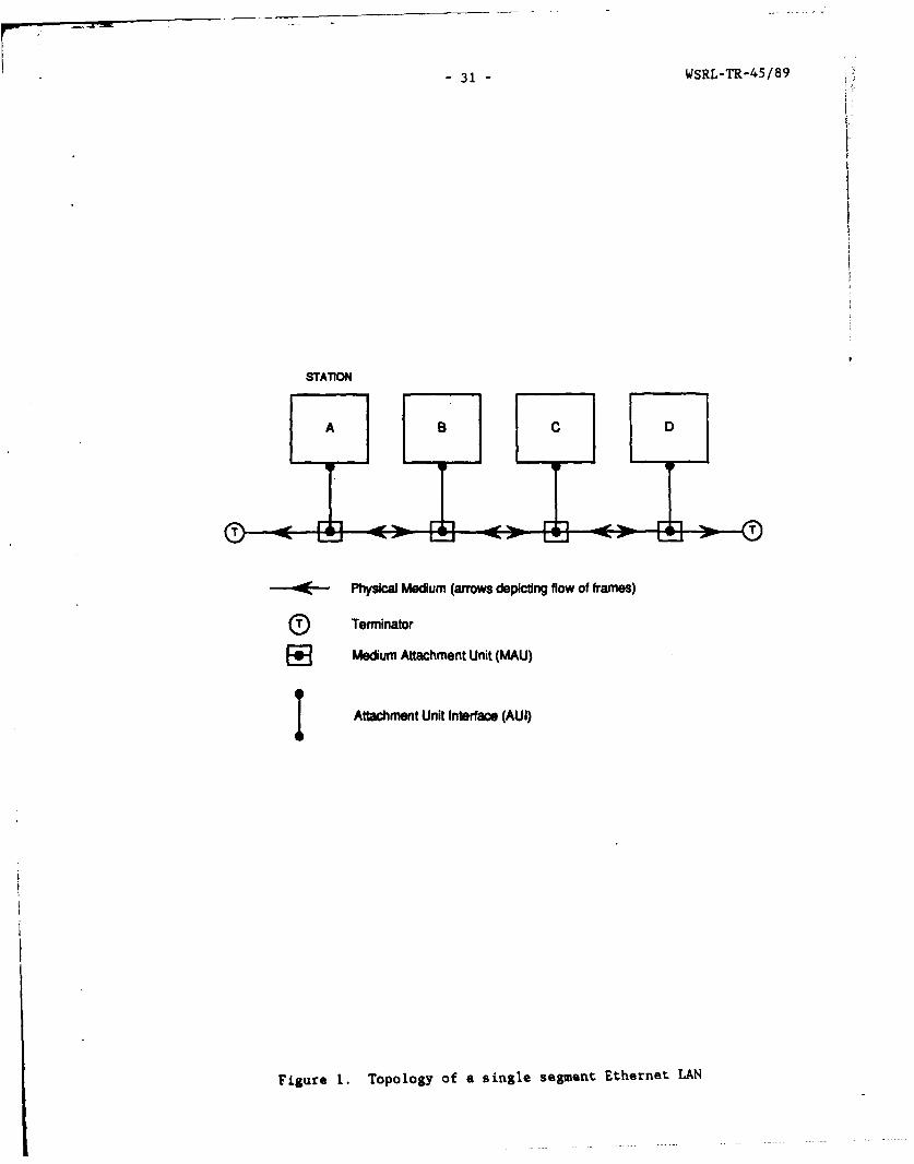
31 -WSRL-TR-45/89
STATION
A BC D
-~--- Physical Medium (arrows depicting flow of frames)
Terminator
EE Medium Attachment Unit (MAU)
I Attachment Unit Interface (AUI)
Figure 1. Topology of a single segment Ethernet LAN

WSRL-TR-45/89 -32-
051REFERENCE MODEL LAN
LAYERS
HIGHER LAYERS
APPLICATION______________LLC
PRESENTATION LOIA IKCNRLDATA TERMINAL.__._._.._._..._........... EQUIPMENT (DTE)
SESSION
TRANSPORT /
NETWORK '/ATTACHMENT UNITINTERFACE (AUI)
DATA LINK
MEDIUM ATTACHMENTPHYSICAL 1 UNIT(MAU)
- Ethernet
Figure 2. Relationship of Ethernet LAN to OSI Reference MIodel

33 -WSRL-TR-45/89
Frame GenerationProcess(Fig 4)
Figure 3.Trchsiiecur ofliio thStereoe sn
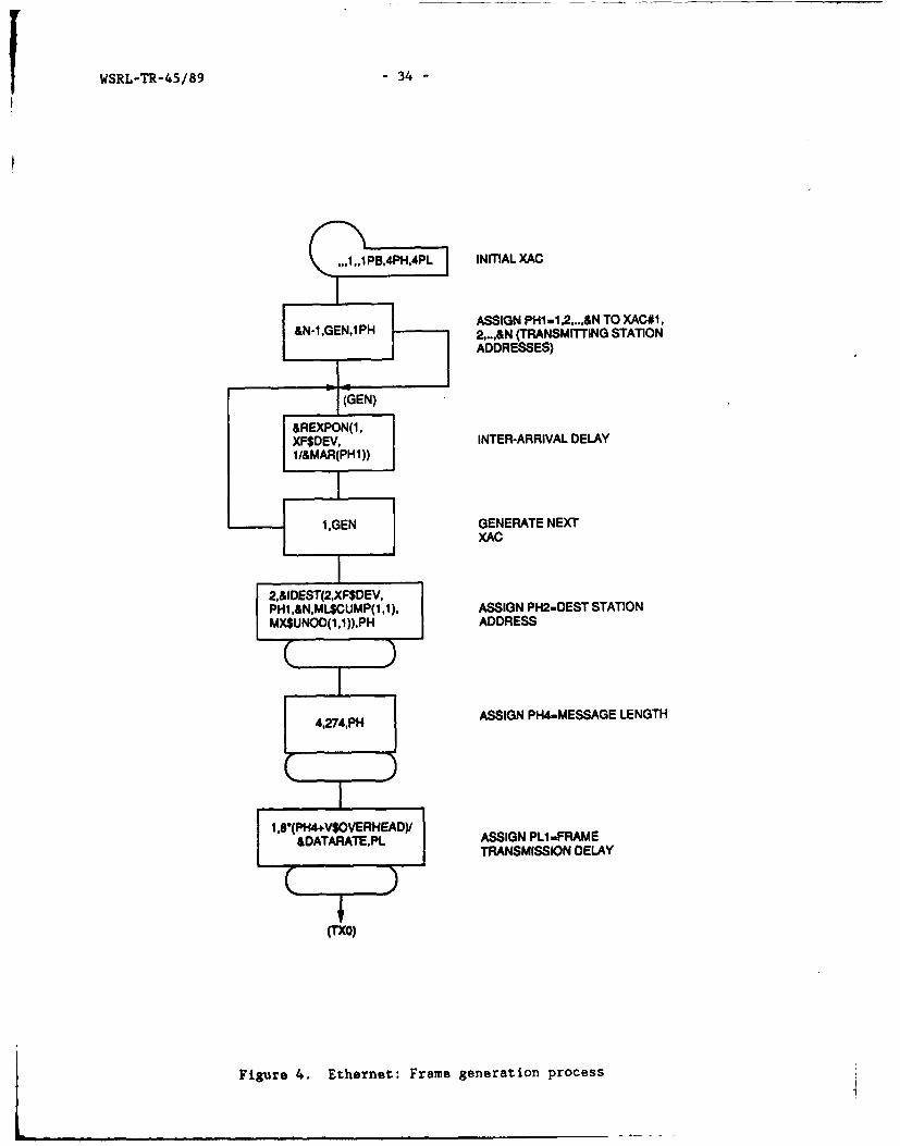
WSRL-TR-45/89 -34-
1 ,,1 PB,4PH,4PL INITIAL XAC
ASSIGN PHI -1 .2,..,&N TO XAC#1,&N-1,GEN,lPH 2,..,&N (TRANSMITTING STATION
ADDRESSES)
XF$DEVINTER-ARRIVAL DELAY
1,GENGENERATE NEXTL-L I IXAC
2,&IDEST(2,XF$DEV,PHI .&N,ML$CUMP(1 .1), ASSIGN PH2wDEST STATIONMX$UNOD(1 ,1)),PH ADDRESS
4.274,PH ASSIGN PH44.MESSAGE LENGTH
1,8(PH4+V$OVERHEAD)I SINPi-RM
&DATARTEPLTRANSMISSION DELAY
(TXO)
Figure 4. Ethernet: Frame generation process

-35- WSRL-TR-45/89
DENOTE END OFTRANSMISSION
(TXGIBRNHI NT CNPHI) L I 3..I.PH
BUFFER IS FULL (TIM)
ASSIGN PL2.TlME MAC TOR SEACD ENOFRERECEIVES REQUEST T
ENOUEJE PHIREQUEST
(ThI) MARK TIME TRANSMISSIONCOMMENCES
WAIT FOR CLEARR LS(PHI W
TO SEND *T
NPH
TO SENO WAIT UNTIL COLLISION
OR TX COMPLETE
iNTIALISE MAX
BACKFF ELAY MA=ELPI.I.OTD~h&S PHI (TXM BRANCH IF TRANSMISSIONSETETC) COMPLETE
SEIZE TXMi &PREMOEJ.
L BRANCH IF PREAMBLE
COMMWENCE 3.-i PH COMLETETRANSMISSION
&PREAMDE. WAIT UNTIL PREAMBLESEJN0 START OF A.X03H-ICMLTFRAME TO EACH S.hB3H-tCMLTNODE IIRDL
INITIATE O.LISION ITI -, (TXIP TTRAP POCESS PRESS
TRANSMISSION DELAY PUI PHIA
RELEASE TX PHI
SEND END OF FRAME IT" USOTO EACH NODEEO
FigureASSERT DELAY
SiTENFRAME DEAYML TV1
RECEPTIONDEOUEUE NEXTi (TCS) PROCESSREOUESTT
DELETEECHOES
Figure 5. Ethernet: Frame transmission process

WSRL-TR-45/89 -36-
(TX1 2)
IXH\ SEIZE TX (COMMENCEH JAMMING)
&JAMDEL JAM DELAY
Hi RELEASE TX
1 .TX5 (T5) END OF JAM
5+,1,PHINCREMENT ATTEMPT COUNT
H5 LE WMXTM BRANCH IF LIMIT EXCEEDED
(TX4)(I.E., ABORT)
PH5 L(E OTRNT BRANCH IF ATTEMPT CNT
(TX13)EXCEEDS THRESHOLD
MAXBKEL+,PI~lMAX BACKOFF DELAY X2
ML$MAXBKDEL(PHI ,1).ML
(TXI 3)
Figure 6. Ethernet: Jam and collision recovery process

- 37 - WSRL-TR-4S/89
(TX13)
3ARUNIF(.XFOEV,.0, ACOMPUTE MLSMAXBKDEL(Pt.I.)).PLRANDOMBACKOFF DELAY Pt.4 INTERFRAME ELAY
INTERRAME DELAY INTERFRAME TIMEOUr
3.PU-I.PI. COMPUTE
OELAY> BACOFFDELAY .ACKOF18
MARK TIME OF ENTRY TOEACKOF DELAY STATE EA M I
Fi rTX21 TO PROCEED
1,X21 M1MARK TIME OF ENTRYTO BACKOFF STATE
BRANCH IF INTERFRAME LDELAY 3. BACKOFF DELAY 1 s (XB
BACKOFF TIMEDUT 1BACKOFF TIMEOUT
COMPUTE .L-.PINTERPRAME RETRANSMIT FRAMEDELAY REMAINN
ENTER DELAY WAIT STATE PU4
RETRANSMIT FRAME L T3
Figure 6 (Contd.)

WSRL-TR-45/89 - 38-
MIXS) (H) C0WAIT UNTIL LS(PHI). UVFC E IWI NICARRIER ON. FNU(V$FAC) E 1 NVIA) EAIUTIOR SACKOFF CARRIER OFF,TIMEOUT TMOI
BRNHFPI(X2 H MBRANCH IF1BACKOFF TIMEOUT CRIRO
*.TX22..RE AC)22.E F
VSFAC SA
COMPUTE 3*Pt.3-,JI*PI.,L-MLCOPTBACKOFF 1BACKOFF DELAYDELAY REMAININGREANG
19)MARK TIME OF ENTRYTO B3ACKOFF DEFER (X4 OTSTATE AKF
LS(P141)+FNU(VIFAC) E IWAIT UNTIL
CARRIER ON OR~A TIMEOUT
BACKFF ELAYPL3BRANCH IFS PHIDELAY TIMERS PHIEXPIRED
BACKOFF TIMEOUT $
ENTER DEFER WAITSTATE (WAIT UNTILCARRIER OFF) PIT2RE AC
VSFAC
REINTALISE 4lDLPINTERFRAME DELAY AMIPCOUT
BACKOFFDELAYREMAINING
GO TO DELAY MSWAIT STATE
GO TOBACKOFF
DEFER STATE
Figure 6 (Contd.)

-39 - WSRL-TR-45/89
GENERATE CONTROL1,1,~~PH XAC
&N-l TX23,IPH GENERATE &N XACS
WITH PHI-i1,2,..&N
< WAIT UNTIL CARRIER ON
S ~DENrjYrE TRANSMIT INHIBIT
R PHIWAIT UNTIL CARRIER OFF
&IFDELINTERFRAME DELAY
R DENOTE CLEAR TOSEND
Figure 7. Ethernet: Collision sensing process

WSRL-TR-45/89 -40-
MAU-MAU PROPAGATIONDEL.AY
pell INCRMETBRANCHIF ENDCONCURFRENCY
OF RNMISO (RIX4) SIMR+.P l..lMX COUNT
ALREADY~(IX4 HEN3.SIRP13l
TECECEN
DETECTDDEAA
DENTE CANOIER
MARE TIMEEATESTAROBRENCHPI ONUINDNT OCRE
SEIZE RECRERIVCOUR
CAREEROOF
DENOTRECERVER
O.M~ CORPONENTD
MA TIMENATRSTART
SEIZERRECEIEE
BRANCHIZ RERECIVERR
CIR OFORCTDF
RELEASERXIRECEIVEDREEIE
BY ACORUSE MORELEASEs
Figure 8. Et er et Fram reception pR oCE ssE

41 -WSRL-TR-45/89
10
9
Mod*A imbon9- .
Mod -B d 1ato 195%C.
60 2040608010Iomlie mIa Ihoghu I(%) IIII
Figur 9. Itent Mea V nse dea I s iea throghpu

WSRL-TR-45/89 -42-
Model "A" simulation
-- ThJory
0. . -~
004
0
Nomalised nmn thrughput()
Figure 10. Ethernet: Probability of zero channel assignment delay vs meanthroughput

43 -WSRL-TR-45/89
* Model "A" simulsm
ti-ii
00
.001
0 20 40 60 t0o10
Normalised mean throughput(%
Figure 11. Ethernet: Probability of buffer overflow vs mean throughput

WSRL-TR-45/89 -44-
Model "A" simulation---
0.0.
Figure12. Eternet Trnsite and resive tlstin smantruhu

-45- WSRL-TR-45/89
STATION
A C D
Physicai Medum (arrows depicting flow of frames and token)
Al stations are active except B (which Is In bypass mode)
Figure 13. Topology of a Token Ring LAN

WSRL-TR-45/89 -46-
Os'REFERENCE MODEL LAN
LAYERS
APPLICATION
PRESENTATION
SESSION
TRANSPORT
NTOKLOGICAL UINK CONTROL R:, E,
DATA LINK
PHYSICAL
SToken Ring
Figure 14. Relationship of Token Ring LAN to OSI Reference Model

-47 - WSRL-TR-45/89
,*,i,1 14,1Pt.INTAL XAC
AN-I.ENOREPLICATE XAC AND
&NI.G NO ASIGN PHI -1,2,..,&Nl TOiPH XACI1.2...,&N
(TRANSMITTING STATION ADDRESSES)
(GENO)
&REXPON(1 ,XF$OEV,INEARVADLY1 .0/ML$STAT(PH1 .3))INE-RVADLY
GENERATE NEXTI .GEN AC
XF$DEV.ML$STAT(PH1 .4))) ASSIGN PLI - FRAME/&DRATE.PL TRANSMISSION DELAY
Tkn RESAMPLE IF TX DELAYTOO LARGE
GAGG INCREMENTAGGREGRATEQUEUE LENGTH
S LOP DENOTE FRAME ARRIVAL
PHI ENOUEUEFIFO FRAME
Figure 15. Token Ring: Frame generation process

WSRL-TR-43/89 -48-
.. 1jP14 EA1ITOKEN
S LOOP WAIT PW RAMEANWIAL
II~teN.IIWASSM4PNi.NSC STATIONAOOWUS
.SSTATPHI.4 STATION LATENCY
~OUEII
FRAME
P-Pam
Figure~BYT1O 160oe ig rmedlvr rcs

49 -WSRL-TR-45/89
SSimawzian 95% ca.
-Theory
10
9
8
7
6.
I -
0 20 40 60 s0 100
Normalised mean throughput()
Figure 17. Taken Ring: Mean transfer delay vs mean throughput

WSRL-TR-45/89 - 50-
THIS IS A BLANK PAGE
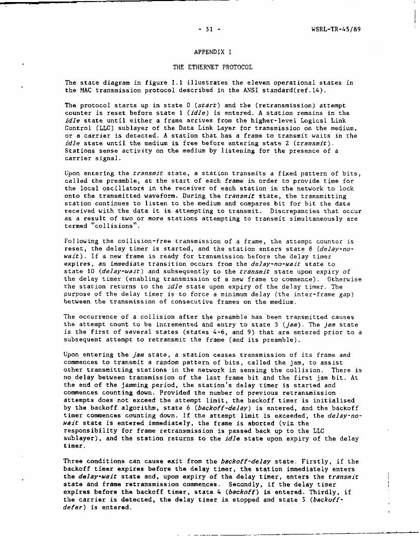
- 51 - WSRL-TR-45/89
APPENDIX I
THE ETHERNET PROTOCOL
The state diagram in figure I.1 illustrates the eleven operational states inthe MAC transmission protocol described in the ANSI standard(ref.14).
The protocol starts up in state 0 (start) and the (retransmission) attemptcounter is reset before state 1 (idle) is entered. A station remains in theidle state until either a frame arrives from the higher-level Logical LinkControl (LLC) sublayer of the Data Link Layer for transmission on the medium,or a carrier is detected. A station that has a frame to transmit waits in theidle state until the medium is free before entering state 2 (transmit).Stations sense activity on the medium by listening for the presence of acarrier signal.
Upon entering the transmit state, a station transmits a fixed pattern of bits,called the preamble, at the start of each frame in order to provide time forthe local oscillators in the receiver of each station in the network to lockonto the transmitted waveform. During the transmit state, the transmittingstation continues to listen to the medium and compares bit for bit the datareceived with the data it is attempting to transmit. Discrepancies that occuras a result of two or more stations attempting to transmit simultaneously aretermed "collisions".
Following the collision-free transmission of a frame, the attempt counter isreset, the delay timer is started, and the station enters state 8 (delay-no-wait). If a new frame is ready for transmission before the delay timerexpires, an immediate transition occurs from the delay-no-wait state tostate 10 (delay-wait) and subsequently to the transmit state upon expiry ofthe delay timer (enabling transmission of a new frame to commence). Otherwisethe station returns to the idle state upon expiry of the delay timer. Thepurpose of the delay timer is to force a minimum delay (the inter-frame gap)between the transmission of consecutive frames on the medium.
The occurrence of a collision after the preamble has been transmitted causesthe attempt count to be incremented and entry to state 3 (jam). The jam stateis the first of several states (states 4-6, and 9) that are entered prior to asubsequent attempt to retransmit the frame (and its preamble).
Upon entering the jam state, a station ceases transmission of its frame andcommences to transmit a random pattern of bits, called the jam, to assistother transmitting stations in the network in sensing the collision. There isno delay between transmission of the last frame bit and the first jam bit. Atthe end of the jamming period, the station's delay timer is started andcommences counting down. Provided the number of previous retransmissionattempts does not exceed the attempt limit, the backoff timer is initialisedby the backoff algorithm, state 6 (backoff-delay) is entered, and the backofftimer commences counting down. If the attempt limit is exceeded, the delay-no-wait state is entered immediately, the frame is aborted (viz theresponsibility for frame retransmission is passed back up to the LLCsublayer), and the station returns to the idle state upon expiry of the delaytimer.
Three conditions can cause exit from the backoff-delay state. Firstly, if thebackoff timer expires before the delay timer, the station immediately entersthe delay-wait state and, upon expiry of the delay timer, enters the transmitstate and frame retransmission commences. Secondly, if the delay timerexpires before the backoff timer, state 4 (backoff) is entered. Thirdly, ifthe carrier is detected, the delay timer is stopped and state 5 (backoff-
defer) is entered.

WSRL-TR-45/89 - 52 -
In the backoff state, the reception of a carrier causes entry to the backoff-defer state. Expiry of the backoff timer, on the other hand, causes transitionto the transmit state and frame retransmission commences.
In the backoff-defer state, the sensing of the end of the carrier starts thedelay timer and causes entry to the backoff-delay state. Expiry of the backofftimer, on the other hand, causes transition to state 9 (defer-wait).Subsequent sensing of the end of the carrier whilst a station is in the defer-wait state starts the delay timer and causes entry to the delay-wait state.
State 7 (defer-no-wait) is entered from the idle state if a station with noframe to transmit detects a carrier. The station remains in this state untileither the end of carrier is sensed or a frame becomes ready to transmit. Ifthe end of carrier is sensed, the delay timer is started and the delay-no-waitstate is entered. If a frame is ready for transmission, the defer-wait stateis entered.
The state diagram of the MAC operational receiving protocol is illustrated infigure 1.2. It consists of only three states. The protocol starts up instate 0 (start) and immediately enters state 1 (idle). Upon detection of acarrier, a station enters state 2 (receive) and returns to the idle state atthe end of reception of a frame (ie., when the end of carrier is sensed).Received frames which are correctly addressed are passed up to the LLCsublayer. On the other hand, collision fragments (viz partially transmittedframes with jams appended) are ignored. Collision fragments are recognised bythe fact that their lengths are always shorter than the minimum frame length.

53 -WSRL-TR-45/89
CAMEM DO
ON DONE DONAE
To * OLY1UCTO
Figue 11 Stte iagrm o Ethrne MACtrasmitproo To

WSRL-TR-45/89 -54-
CARRIER ON
CARRIER OFF
Figure 1.2 State diagram of Ethernet MAC receive protocol
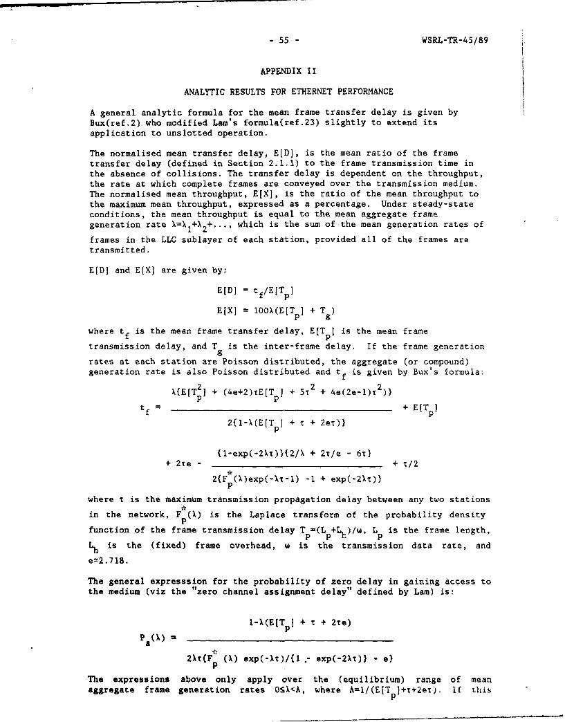
- 55 - WSRL-TR-45/89
APPENDIX II
ANALYTIC RESULTS FOR ETHERNET PERFORMANCE
A general analytic formula for the mean frame transfer delay is given byBux(ref.2) who modified Lam's formula(ref.23) slightly to extend itsapplication to unslotted operation.
The normalised mean transfer delay, E[D], is the mean ratio of the frametransfer delay (defined in Section 2.1.1) to the frame transmission time inthe absence of collisions. The transfer delay is dependent on the throughput,the rate at which complete frames are conveyed over the transmission medium.The normalised mean throughput, E[XJ, is the ratio of the mean throughput tothe maximum mean throughput, expressed as a percentage. Under steady-stateconditions, the mean throughput is equal to the mean aggregate framegeneration rate X=X I+ 2+ ..., which is the sum of the mean generation rates of
frames in the LLC sublayer of each station, provided all of the frames aretransmitted.
E[D] and E[X] are given by:
E[D] = tf/E[Tp]
E[X] = O0OX(E[T p] + T )
where tf is the mean frame transfer delay, E[T ] is the mean frame
transmission delay, and T is the inter-frame delay. If the frame generationgrates at each station are Poisson distributed, the aggregate (or compound)generation rate is also Poisson distributed and tf is given by Bux's formula:
X{E[T 2] + (4e+2)TE[T + 5T2 + 4e(2e-l)T2)}p p
tf = + E[T p
2{I-X(E[Tp] + T + 2eT)}
(l-exp(-2X))(2/X + 2r/e - 6T)+ 2re - + T/2
2{F ()exp(-X'-l) -1 + exp(-2Xi)}
where i is the maximum transmission propagation delay between any two stations
in the network, Fp (X) is the Laplace transform of the probability density
function of the frame transmission delay Tp=(Lp+L)/w, Lp is the frame length,
Lh is the (fixed) frame overhead, w is the transmission data rate, and
e=2.718.
The general expresssion for the probability of zero delay in gaining access tothe medium (viz the "zero channel assignment delay" defined by Lam) is:
1-X(E[Tp] + r + 2%e)P ( ) = _ _ _ _ _ _ _ _ _ _ _ _ _ _ _ _ _ _ _
2kt{Fp (X) exp(-XT)/(l .- exp(-2Xt)) - e)
The expressions above only apply over the (equilibrium) range of mean
aggregate frame generation rates O:X<A, where A=I/(EIT p+t+2ei). If this

WSRL-TR-45/89 - 56 -
condition is satisfied, individual frame transfer delays are bounded. Themaximum mean throughput depends upon three factors: the mean frame length,(E[Lp]+Lh), the physical dimensions of the network (which govern T), and the
bandwidth of the transmission medium (w). In practice, propagation delays canonly be ignored in highly localised networks or when mean frame lengths arelarge.
For the constant frame lengths assumed in the simulation experiments, thefirst two moments and the Laplace transform of the frame transmission delaydistribution are given by:
E[T] = (Lp+Lh)/W,
E[T ] = E 2[Tp*p p
and F (X) exp(-X[L- 41h]/w).
The maximum value of the normalised mean throughput is given by:
lO0(Lp + Lh + wT )
E[X max =L + h + (1 + 2e)rw
In the previous analysis it was assumed that all of the frames generated bythe LLC sublayer are accepted for transmission by the MAC sublayer. Thisimplies the presence of a buffer which is sufficiently large to store framesgenerated whilst transmissions are in progress. However, in practice, eachstation incorporates only a unit-capacity MAC buffer, so that there is afinite probability that the buffer will be full (viz "overflow") at the time aframe is offered to the MAC sublayer. In this case, the frame is eitherrescheduled by the LLC sublayer for later transmission, or aborted. Thenormalised mean throughput is related to the mean aggregate frame generationrate by:
E[X] = 10OX(E[T p] + T ).(l-Pb()
No closed-form expression exists for the buffer overflow probability, Pb(X),
but numerical solutions may be obtained by iteratively solving the Markovbalance equations(ref.5).
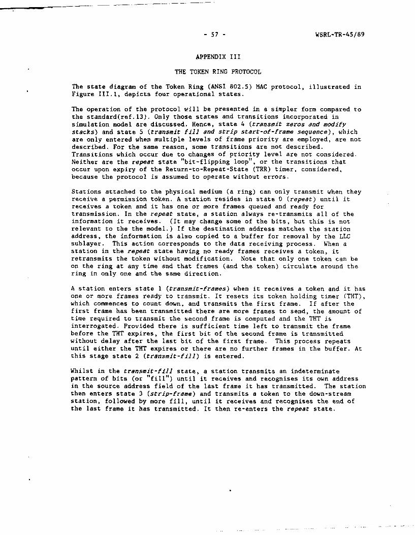
- 57 - WSRL-TR-45/89
APPENDIX III
THE TOKEN RING PROTOCOL
The state diagram of the Token Ring (ANSI 802.5) MAC protocol, illustrated inFigure III.1, depicts four operational states.
The operation of the protocol will be presented in a simpler form compared tothe standard(ref.13). Only those states and transitions incorporated insimulation model are discussed. Hence, state 4 (transmit zeros and modifystacks) and state 5 (transmit fill and strip start-of-frame sequence), whichare only entered when multiple levels of frame priority are employed, are notdescribed. For the same reason, some transitions are not described.Transitions which occur due to changes of priority level are not considered.Neither are the repeat state "bit-flipping loop", or the transitions thatoccur upon expiry of the Return-to-Repeat-State (TRR) timer, considered,because the protocol is assumed to operate without errors.
Stations attached to the physical medium (a ring) can only transmit when theyreceive a permission token. A station resides in state 0 (repeat) until itreceives a token and it has one or more frames queued and ready fortransmission. In the repeat state, a station always re-transmits all of theinformation it receives. (It may change some of the bits, but this is notrelevant to the the model.) If the destination address matches the stationaddress, the information is also copied to a buffer for removal by the LLCsublayer. This action corresponds to the data receiving process. When astation in the repeat state having no ready frames receives a token, itretransmits the token without modification. Note that only one token can beon the ring at any time and that frames (and the token) circulate around thering in only one and the same direction.
A station enters state 1 (transmit-frames) when it receives a token and it hasone or more frames ready to transmit. It resets its token holding timer (THT),which commences to count down, and transmits the first frame. If after thefirst frame has been transmitted there are more frames to send, the amount oftime required to transmit the second frame is computed and the THT isinterrogated. Provided there is sufficient time left to transmit the framebefore the THT expires, the first bit of the second frame is transmittedwithout delay after the last bit of the first frame. This process repeatsuntil either the TnT expires or there are no further frames in the buffer. Atthis stage state 2 (transmit-fill) is entered.
Whilst in the transmit-fill state, a station transmits an indeterminatepattern of bits (or "fill") until it receives and recognises its own addressin the source address field of the last frame it has transmitted. The stationthen enters state 3 (strip-frame) and transmits a token to the down-streamstation, followed by more fill, until it receives and recognises the end ofthe last frame it has transmitted. It then re-enters the repeat state.

WSRL-TR-45/89 - 58-
TOKEN RECEIVED a
TOKENLAST FRAME& OR
FILL ThT EXPIRED
Figure 11I.1 State diagram of Token Ring MAC protocol

- 59 WSRL-TR-45/89
APPENDIX IV
ANALYTIC RESULTS FOR TOKEN RING PERFORMANCE
A general analytic formula for the mean frame transfer delay is given byBux(ref.2) who modified Konheim and Meister's discrete-time formula(ref.23) toobtain a continuous-time approximation.
Under steady-state conditions the mean throughput is equal to the meanaggregate frame generation rate, X, and the normalised mean throughput isgiven by
E[X] = lOOXE[T ].
Expressions for the the mean frame transmission delay, E[T p], and the
normalised mean transfer delay, E[D], appear in Appendix II.
Analytic results exist only for the restricted case in which all stationsgenerate the same amount of traffic, viz the frame generation ratedistributions are identical. A simplified solution is obtained by assumingthat all of the frames generated by the LLC sublayer are accepted fortransmission by the MAC sublayer. This implies that the buffer in the MACsublayer of each station is large enough to store all of the frames prior totransmission. The normalised mean throughput can achieve a maximum of 100%.
Bux's simplified solution for the mean transfer delay, tf, additionally
assumes Poisson distributed frame generation rates and equal station
latencies:
XE[T ]E[T 2(I-XE[Tp]/N)
tf = + E[T pJ + + T/22-g[p)[p] 2(l-XE[Tp])
2C1-XE[T pJ)E[T ] (-ETP1
where N is the number of stations, T is the station latency (X=T+q, where q isthe minimum token holding time) and the other symbols have the same meaningsas in Appendix II. This formula only applies over the equilibrium range offrame generation rates OSX<1/E[Tp J. Within this range, individual frame
transfer delays are bounded.
In the simulation experiment the values of L are assumed to be exponentiallypdistributed with a mean of E[Lp J, hence the first two moments of the frame
transmission delay distribution are given by:
E[T p] = (E[Lp] + Lh)/w, and
E(T = E 2[T + E 2 Lp 11 2.p p p

WSRL-TR-45/89
DISTRIBUTION
Number of copies
Defence Science and Technology Organisation
Chief Defence Scientist ))
First Assistant Secretary, Science Policy ) 1)Director General Science and Technology Programs )
)
Counsellor Defence Science London Cnt Sht Only
Counsellor Defence Science Washington Cnt Sht Only
DSR - Bangkok Cnt Sht Only
SA to DRC - Kuala Lumpur Cnt Sht Only
Weapons Systems Research Laboratory
Director 1
Chief, Combat Systems Division 1
Head, Combat Systems Integration 1
Head, Combat Systems Effectiveness 1
J.G. Schapel, Combat Systems Integration 1
S.J. Miller, Combat Systems Integration 1
M.L. Scholz, Combat Systems Integration 3
Electronics Research Laboratory
Director 1
Head, Switching Signalling and Networks 1
Manager, Information Systems Branch i
Head, Networks 1
Libraries and Information Services
Defence Central Library, Campbell Park 1
Document Exchange Centre,Defence Information Services and Science Liaison Branch for:
Microfilming 1
National Library of Australia 1
United Kingdom, Defence Research Information Centre 2
Canada, Director Scientific Information Services 1

WSRL-TR-45/89
New Zealand, Ministry of Defence 1
United States, Defense Technical Information Center 12
Main Library, Defence Science and TechnologyOrganisation, Salisbury 2
Library, DSD, Melbourne 1
Library, DSTO, Sydney 1
Library, Aeronautical Research Laboratory 1
Library, Materials Research Laboratory 1
Australian Defence Force Academy Library 1
Department of Defence
Director of Departmental Publications 1
Joint Intelligence Organisation (DSTI) 1
Navy Office
Navy Scientific Adviser Cnt Sht Only
Director, Naval Combat Systems Engineering 1
Director, Submarine Warfare Systems Centre Cnt Sht Only
Deputy Director, Development, SWSC 1
Other Departments and Organisations
SA Institute of Technology
Head, School of Mathematics and Computer Studies 1
Dr D.M. Panton, Maths and Computer Studies 1
Director, Digital Communications Group I
Dr J. Asenstorfer, Digital Communications Group 1
Director, Teletraffic Research Centre, Univ of Adelaide 1
Manager, LAN Products Group,AWA Defence and Aerospace, North Ryde NSW 1
UNITED KINGDOM
British Library, Document Supply Centre (UK) 1
Institution of Electrical Engineers (UK) 1
Spares 3
Total number of copies 55

DOCUMENT CONTROL DATA SHEET
Security classification of this page : UNCLASSIFIED
1 DOCUMENT NUMBERS 2 [ SECURITY CLASSIFICATIONa. Complete Unclassified
AR AR-005-937 Document :Number: b. Tle in Unclassified
Isolation:
Series WSRL-TR-45/89 c. Summary in UnclassifiedNumber: Isolation:
Other [DOWNGRADING / DELIMITING INSTRUCTIONS
Numbers:
4TITLE ISIMULATING LOCAL AREA NETWORK PROTOCOLS WITH THE GENERALPURPOSE SIMULATION SYSTEM (GPSS)
5 PERSONAL AUTHOR (S) 6 DOCUMENT DATEMarch 1990
M.L. Scholz
OF PAGES 59
7.2 NUMBER OF 3REFERENCES 3
8 FS. 1 CORPORATE AUTHOR (S) 9 REFERENCE NUMBERS
a. Task : NAY 87/226.2
Weapons Systems Research Laboratory
b. Sponsoring Agency: NAVY
8. 2 DOCUMENT SERIES 10 COST CODEand NUMBER
Technical Report 77923545/89
IMPRINT (Publishing organisation) 12 COMPUTER PROGRAM (S)
Defence Science and Technology
Organisation
13 RELEASE LIMITATIONS (of the document)
Approved for Public Release
Security classification of this page: UNCLASSIFIED
Security classification of this page: UNCLASSIFIED
14 ANNOUNCEMENT LIMITATIONS (of the information on these pages)
No limitation
15 [ DESCRIPTORS 16 FCOSATI CODES
a. EJC Thesaurus GPSS (programming language)Terms Simulation languages 1207
Local area networks
b. Non - ThesaurusTerms Ethernet protocol (computers)
Token Ring protocol (computers)
17 SUMMARY OR ABSTRACT
(if this is security classified, the announcement of this report will be similarly classified)
(U) Simulation models of ANSI 802.3 (Ethernet) and ANSI 802.5 (Token Ring) transmission controlprotocols have been constructed to assess the usefulness of the General Purpose Simulation System(GPSS) simulation language for modelling the performance of local area networks. The models aredescribed in detail and the data obtained from them are compared with analytic results. Modelverification and other problems associated with analysing simulation output are discussed.
Security classification of this page: UNCLASSIFIED