DSL Based on SDR Using FPGA Dr. Hadi T. Ziboon … · Design and Implementation of OFDM ... wave...
5
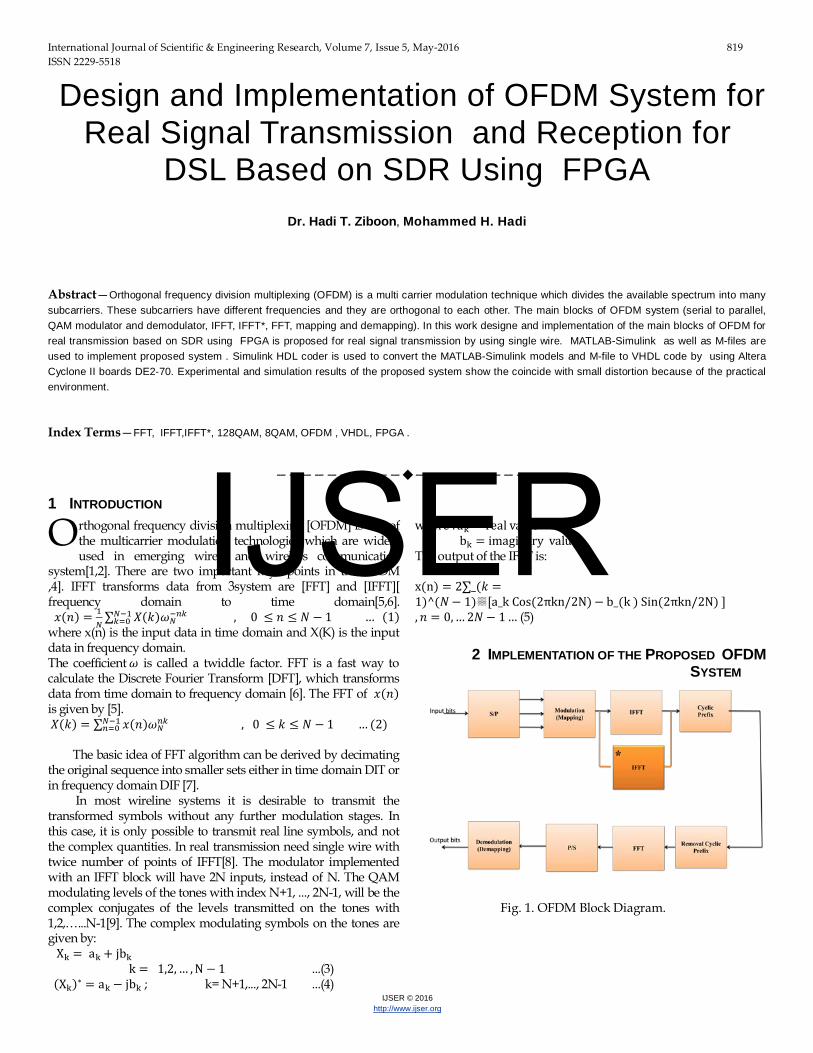
International Journal of Scientific & Engineering Research, Volume 7, Issue 5, May-2016 819 ISSN 2229-5518 IJSER © 2016 http://www.ijser.org Design and Implementation of OFDM System for Real Signal Transmission and Reception for DSL Based on SDR Using FPGA Dr. Hadi T. Ziboon, Mohammed H. Hadi Abstract—Orthogonal frequency division multiplexing (OFDM) is a multi carrier modulation technique which divides the available spectrum into many subcarriers. These subcarriers have different frequencies and they are orthogonal to each other. The main blocks of OFDM system (serial to parallel, QAM modulator and demodulator, IFFT, IFFT*, FFT, mapping and demapping). In this work designe and implementation of the main blocks of OFDM for real transmission based on SDR using FPGA is proposed for real signal transmission by using single wire. MATLAB-Simulink as well as M-files are used to implement proposed system . Simulink HDL coder is used to convert the MATLAB-Simulink models and M-file to VHDL code by using Altera Cyclone II boards DE2-70. Experimental and simulation results of the proposed system show the coincide with small distortion because of the practical environment. Index Terms—FFT, IFFT,IFFT*, 128QAM, 8QAM, OFDM , VHDL, FPGA . ———————————————————— 1 INTRODUCTION rthogonal frequency division multiplexing [OFDM] is one of the multicarrier modulation technologies which are widely used in emerging wired and wireless communication system[1,2]. There are two important key points in the OFDM system are [FFT] and [IFFT][ 3 ,4]. IFFT transforms data from frequency domain to time domain[5,6]. ()= 1 ∑ () − −1 =0 , 0 ≤≤− 1 … (1) where x(n) is the input data in time domain and X(K) is the input data in frequency domain. The coefficient is called a twiddle factor. FFT is a fast way to calculate the Discrete Fourier Transform [DFT], which transforms data from time domain to frequency domain [6]. The FFT of () is given by [5]. ()= ∑ () −1 =0 , 0 ≤≤− 1 … (2) The basic idea of FFT algorithm can be derived by decimating the original sequence into smaller sets either in time domain DIT or in frequency domain DIF [7]. In most wireline systems it is desirable to transmit the transformed symbols without any further modulation stages. In this case, it is only possible to transmit real line symbols, and not the complex quantities. In real transmission need single wire with twice number of points of IFFT[8]. The modulator implemented with an IFFT block will have 2N inputs, instead of N. The QAM modulating levels of the tones with index N+1, ..., 2N-1, will be the complex conjugates of the levels transmitted on the tones with 1,2,…...N-1[9]. The complex modulating symbols on the tones are given by: X k = a k + jb k k= 1,2, … , N − 1 ...(3) (X k ) ∗ =a k − jb k ; k= N+1,..., 2N-1 ...(4) where : a k = real value b k = imaginary value The output of the IFFT is: x(n) = 2∑_( = 1)^(− 1)▒[a_k Cos(2πkn/2N) − b_(k ) Sin(2πkn/2N) ] , = 0, … 2− 1… (5) 2 I MPLEMENTATION OF THE PROPOSED OFDM SYSTEM Fig. 1. OFDM Block Diagram. O IJSER
Transcript of DSL Based on SDR Using FPGA Dr. Hadi T. Ziboon … · Design and Implementation of OFDM ... wave...
International Journal of Scientific & Engineering Research, Volume 7, Issue 5, May-2016 819 ISSN 2229-5518
IJSER © 2016 http://www.ijser.org
Design and Implementation of OFDM System for Real Signal Transmission and Reception for
DSL Based on SDR Using FPGA
Dr. Hadi T. Ziboon, Mohammed H. Hadi
Abstract—Orthogonal frequency division multiplexing (OFDM) is a multi carrier modulation technique which divides the available spectrum into many subcarriers. These subcarriers have different frequencies and they are orthogonal to each other. The main blocks of OFDM system (serial to parallel, QAM modulator and demodulator, IFFT, IFFT*, FFT, mapping and demapping). In this work designe and implementation of the main blocks of OFDM for real transmission based on SDR using FPGA is proposed for real signal transmission by using single wire. MATLAB-Simulink as well as M-files are used to implement proposed system . Simulink HDL coder is used to convert the MATLAB-Simulink models and M-file to VHDL code by using Altera Cyclone II boards DE2-70. Experimental and simulation results of the proposed system show the coincide with small distortion because of the practical environment.
Index Terms—FFT, IFFT,IFFT*, 128QAM, 8QAM, OFDM , VHDL, FPGA .
————————————————————
1 INTRODUCTION rthogonal frequency division multiplexing [OFDM] is one of the multicarrier modulation technologies which are widely used in emerging wired and wireless communication
system[1,2]. There are two important key points in the OFDM system are [FFT] and [IFFT][3,4]. IFFT transforms data from
frequency domain to time domain[5,6]. 𝑥(𝑛) = 1
𝑁∑ 𝑋(𝑘)𝜔𝑁
−𝑛𝑘𝑁−1𝑘=0 , 0 ≤ 𝑛 ≤ 𝑁 − 1 … (1)
where x(n) is the input data in time domain and X(K) is the input data in frequency domain. The coefficient 𝜔 is called a twiddle factor. FFT is a fast way to calculate the Discrete Fourier Transform [DFT], which transforms data from time domain to frequency domain [6]. The FFT of 𝑥(𝑛) is given by [5]. 𝑋(𝑘) = ∑ 𝑥(𝑛)𝜔𝑁
𝑛𝑘𝑁−1𝑛=0 , 0 ≤ 𝑘 ≤ 𝑁 − 1 … (2)
The basic idea of FFT algorithm can be derived by decimating the original sequence into smaller sets either in time domain DIT or in frequency domain DIF [7]. In most wireline systems it is desirable to transmit the transformed symbols without any further modulation stages. In this case, it is only possible to transmit real line symbols, and not the complex quantities. In real transmission need single wire with twice number of points of IFFT[8]. The modulator implemented with an IFFT block will have 2N inputs, instead of N. The QAM modulating levels of the tones with index N+1, ..., 2N-1, will be the complex conjugates of the levels transmitted on the tones with 1,2,…...N-1[9]. The complex modulating symbols on the tones are given by: Xk = ak + jbk k = 1,2, … , N − 1 ...(3) (Xk)∗ = ak − jbk ; k= N+1,..., 2N-1 ...(4)
where : ak = real value bk = imaginary value The output of the IFFT is: x(n) = 2∑_(𝑘 =1)^(𝑁− 1)▒[a_k Cos(2πkn/2N)− b_(k ) Sin(2πkn/2N) ] ,𝑛 = 0, … 2𝑁− 1 … (5)
2 IMPLEMENTATION OF THE PROPOSED OFDM SYSTEM
Fig. 1. OFDM Block Diagram.
O
IJSER

International Journal of Scientific & Engineering Research, Volume 7, Issue 5, May-2016 820 ISSN 2229-5518
IJSER © 2016 http://www.ijser.org
FIG. 2. DESIGN PROCEDURE OF THE PROROSED SDR SYSTEM. Table (1): Design system parameters for ADSL
Fig.1 shows the proposed system design for OFDM
transceiver. In OFDM, serial to parallel conversion is needed to convert the input data to be transmitted in each OFDM symbol. These parallel output are given to QAM modulation. The amount of data transmitted on each subcarrier depends on the constellation. IFFT converts the frequency. After IFFT the cyclic prefix is added in order to reduce the inter carrier interference (ICI). At receiver side the first step is to remove the cyclic prefix. The FFT convert the signal to frequency domain. The FFT output is fed to parallel to serial convertor, these serial output is fed to demapper. The function of demapper is to convert constellation points to the data bit. 3. Simulation Results for Proposed System computational There are two techniques of simulation to simulate the proposed system. The first simulation technique based on MATLAB (MATLAB-Simulink and M-file). The second simulation technique is based on ModelSim. Using VHDL and synthesized using modelsim tools based on using FPGA Altera-
Cyclone II. Simulation results for MATLAB (MATLAB-Simulink and M-file) are shown in fig.3,4,5,6.
Fig. 3.The output signal for 128QAM.
Fig. 4.Output signal for 256 IFFT.
Fig. 5.The output signal for 128FFT.
Parameter Selected types for real
system
Modulation type
8QAM, 128QAM
Number of
subchannels
8 , 128
IFFT size 16 , 256
FFT size 8 , 128
Cyclic Prefix Length 64
Data rate 552 Kbit/sec
Sampling Frequency 1.104 MHz
IJSER

International Journal of Scientific & Engineering Research, Volume 7, Issue 5, May-2016 821 ISSN 2229-5518
IJSER © 2016 http://www.ijser.org
Fig. 6.The output signal for demapper.
The simulated wave form of OFDM transmitter and receiver are shown in:- Figure (7) describe the output signal for 128 QAM. Figure (8) describe the output signal for IFFT. Figure (9) describe the output signal after a cyclic. Figure (10) describe the output signal for serial 128 FFT. Figure (11) describe the output signal for demapper.
Fig. 7.The output signal for 128 QAM.
Fig. 8.The output signal for IFFT.
Fig. 9.The output signal after cyclic prefix (cp).
Fig. 10.The output signal for 128 FFT.
Fig. 11.The output signal for demapper.
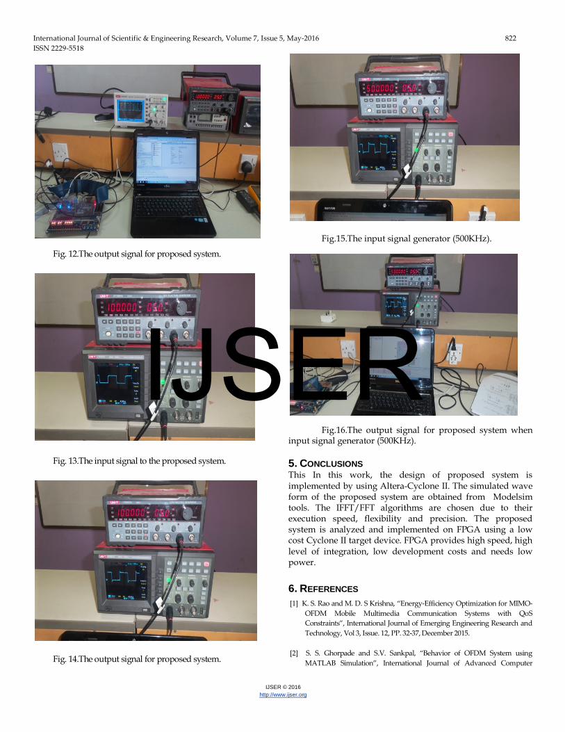
4. EXPERIMENTAL RESULTS Figure (12) describe the output signal from proposed
system when input signal generator is (10KHz). Figure (13) describe the input signal generator (100KHz) to the proposed system. Figure (14) describe the output signal for proposed system when input signal is (100KHz). Figure (15) describe the input signal generator (500KHz) to the proposed system. Figure (16) describe the output signal for proposed system when input signal generator is (500KHz).
IJSER
International Journal of Scientific & Engineering Research, Volume 7, Issue 5, May-2016 822 ISSN 2229-5518
IJSER © 2016 http://www.ijser.org
Fig. 12.The output signal for proposed system.
Fig. 13.The input signal to the proposed system.
Fig. 14.The output signal for proposed system.
Fig.15.The input signal generator (500KHz).
Fig.16.The output signal for proposed system when
input signal generator (500KHz).
5. CONCLUSIONS This In this work, the design of proposed system is implemented by using Altera-Cyclone II. The simulated wave form of the proposed system are obtained from Modelsim tools. The IFFT/FFT algorithms are chosen due to their execution speed, flexibility and precision. The proposed system is analyzed and implemented on FPGA using a low cost Cyclone II target device. FPGA provides high speed, high level of integration, low development costs and needs low power.
6. REFERENCES [1] K. S. Rao and M. D. S Krishna, “Energy-Efficiency Optimization for MIMO-
OFDM Mobile Multimedia Communication Systems with QoS Constraints”, International Journal of Emerging Engineering Research and Technology, Vol 3, Issue. 12, PP. 32-37, December 2015.
[2] S. S. Ghorpade and S.V. Sankpal, “Behavior of OFDM System using
MATLAB Simulation”, International Journal of Advanced Computer
IJSER

International Journal of Scientific & Engineering Research, Volume 7, Issue 5, May-2016 823 ISSN 2229-5518
IJSER © 2016 http://www.ijser.org
Research (ISSN (print):2249-7277 ISSN (online):2277-7970) Vol. 3, Number-2 Issue-10, pp. 1-5, June-2013.
[3] A. Amrutha, S. Jacob, V. V. Gopal, “Implementation of Orthogonal
Frequency Division Multiplexing Transceiver on FPGA”, International Journal of VLSI and Embedded Systems-IJVES, Vol. 05, Article 08393, November 2014.
[4] S. M. Nejakar, P. G. Benakop, and R. R. Sharanabasappa,“Orthogonal Frequency Division Multiplexing Modulation Schemefor 4G/5G Cellular Network”, European Journal of Advances in Engineering and Technology, 2(3): 46-50, 2015.
[5] Sh. Chen, C. Yu, C. Tsai and J. Tang, “A New IFFT/FFT Hardware
Implementation Structure for OFDM Applications”, IEEE Asia-Pacific Conference on Circuits and Systems, pp. 1093-1096, December 2004.
[6] N. A. Galande, A. M. Shah, “Concepts and Brief Survey of Conventional and Wavelet OFDM: Review”, International Journal of Science, Engineering and Technology Research (IJSETR), Vol. 5, Issue 1, January 2016.
[7] A. Saini, V. Bhandari, “OFDM Transmission and Reception: Review”, International Research Journal of Engineering and Technology (IRJET), Vol. 02, Issue. 02, May-2015.
[8] A. R. S. Bahai and B. R. Saltzberg, “Multi-Carrier Digital Communications Theory and Applications of OFDM”, Kluwer Academic Publishers, 2002.
[9] H. T. Ziboon and I. M. Farhan, “Design and Implementation of Discrete Multitone Modulator for Digital Subscriber Line Using FPGA ”, Eng. & Tech. Journal , Vol. 32, Part(A), No 7, 2014.
IJSER