DSA interface protocol & command set - search...
36
Premium 10501 23-04-01 P10501A08.DOC draft DSA Interface Description; Premium10501 Philips components ª2000 Philips Electronics. All rights reserved Page 1 PHILIPS OPTICAL STORAGE Philips Components DSA INTERFACE BUS PROTOCOL & DSA COMMAND SET PREMIUM 10501
Transcript of DSA interface protocol & command set - search...

Premium 10501 23-04-01P10501A08.DOC draft DSA Interface Description; Premium10501
Philips components ã2000 Philips Electronics. All rights reserved Page 1
PHILIPS OPTICAL STORAGE
Philips Components
DSA INTERFACE BUS PROTOCOL&
DSA COMMAND SET
PREMIUM 10501

Premium 10501 23-04-01P10501A08.DOC draft DSA Interface Description; Premium10501
Philips components ã2000 Philips Electronics. All rights reserved Page 2
Revision history
Version Date Remarks
Release 0.1 12-09-97 Derived from Premium 6000 DSA command description and adaptedfor Premium 7000
Release 0.2 24-11-97 Chapter 3.20. Added, Note: This command .........03-03-00 Update from Premium 10500
Preface
This document describes the DSA (Data Strobe Acknowledge) interface bus protocol and DSA commandset of the Premium 10501.
The Premium 10501is the reference tool for the VAU1254/ 1255 which can be used for High-end audio,Jukebox and Video-CD applications.
The DSA-interface is an interface used for communication between two processors. One is called theservo processor and the other the user processor.
The servo processor in the CD-Module controls all servo activities, like play, pause, jumping, readingsubcode, etc.
The user processor controls the servo processor via the DSA-interface.
This document gives information to users who want to control the CD-Module, and for those who want towrite the user processor control SW to make their own High-end Audio, Jukebox and Video-CDapplications.

Premium 10501 23-04-01P10501A08.DOC draft DSA Interface Description; Premium10501
Philips components ã2000 Philips Electronics. All rights reserved Page 3
PHILIPS OPTICAL STORAGE
DSA INTERFACE BUS PROTOCOL&
DSA COMMAND SET
PREMIUM 10501
Author(s)
Alice You
Philips ComponentsOptical Storage
Development A/V Shanghai
Keywords:High-end Audio
JukeboxDSACD10
VAU1254/1255Premium 10501
Philips Components
Premium 10501 23-04-01P10501A08.DOC draft DSA Interface Description; Premium10501
Philips components ã2000 Philips Electronics. All rights reserved Page 4
Table of Contents
INTRODUCTION..................................................................................................................................................5
1.1 PURPOSE.................................................................................................................................................... 51.2 SCOPE........................................................................................................................................................ 51.3 UPDATE INFORMATION ........................................................................................................................... 5
2. DSA-INTERFACE.........................................................................................................................................6
2.1 GENERAL DESCRIPTION .......................................................................................................................... 62.2 DSA-INTERFACE SPECIFICATION........................................................................................................... 62.3 DESCRIPTION OF COMMUNICATION....................................................................................................... 6
2.3.1 Starting synchronisation ............................................................................................................... 72.3.2 Data Transmission ......................................................................................................................... 72.3.3 Communication acknowledge...................................................................................................... 8
3. DSA COMMAND SET...............................................................................................................................12
3.1 VENDOR UNIQUE DSA COMMANDS................................................................................................... 123.2 COMMAND RULES.................................................................................................................................. 133.3 COMMAND RECOVERY.......................................................................................................................... 133.4 COMMAND SET SUMMARY.................................................................................................................... 133.5 PLAY TITLE ............................................................................................................................................. 183.6 STOP ........................................................................................................................................................ 193.7 READ TOC .............................................................................................................................................. 203.8 READ LONG TOC................................................................................................................................... 203.9 SET MODE............................................................................................................................................... 223.10 GET LAST ERROR.................................................................................................................................... 233.11 CLEAR ERROR......................................................................................................................................... 233.12 SPIN UP .................................................................................................................................................... 233.13 PAUSE ...................................................................................................................................................... 233.14 PAUSE RELEASE ..................................................................................................................................... 243.15 SEARCH FORWARD/BACKWARD ......................................................................................................... 243.16 SEARCH RELEASE .................................................................................................................................. 243.17 GET TITLE LENGTH ................................................................................................................................ 253.18 GET COMPLETE TIME ............................................................................................................................. 253.19 GOTO TIME .............................................................................................................................................. 253.20 GET DISC IDENTIFIERS.......................................................................................................................... 263.21 PLAY A-TIME TILL B-TIME ................................................................................................................... 273.22 RELEASE A->B TIME ............................................................................................................................. 293.23 GET DISC STATUS.................................................................................................................................. 293.24 SET VOLUME .......................................................................................................................................... 293.25 CLEAR TOC ............................................................................................................................................ 313.26 SET DAC MODE (I2S OUTPUT FORMAT )............................................................................................ 313.27 SERVICE CONTROL COMMANDS........................................................................................................... 323.28 ERROR HANDING.................................................................................................................................... 343.29 ERROR CODE TABLE .............................................................................................................................. 35
4. EMERGENCY STOP.................................................................................................................................35
5. TEST LOOPS COMMAND SET ............................................................................................................36

Premium 10501 23-04-01P10501A08.DOC draft DSA Interface Description; Premium10501
Philips components ã2000 Philips Electronics. All rights reserved Page 5
Introduction
1.1 Purpose
This document is the first release that describes the Data Strobe Acknowledge (DSA) interface of thePremium 10501 which can be used for High-end audio, Jukebox and Video-CD applications.
The DSA-interface is an interface used for communication between two processors. One is called theservo processor and the other the user processor.
The servo processor in the CD-Module controls all servo activities, like play, pause, jumping, readingsubcode, etc.
The user processor controls the servo processor via the DSA-interface.
1.2 Scope
This document gives information to users who want to control the CD-Module, and for those who want towrite user processor control SW to make their own High-en audio, Jukebox and Video-CD applications.
1.3 Update information
First document release:Derived from DSA Command set for PREMIUM 6000 document, Release 1.1 from 25 October 1994.Added: Search release in chapter 3.4 Command set summary
Laser on/of in chapter 3.4 Command set summaryOpcode 81, 82 in “Set Dac mode”
Changed: Some editorial improvements implemented

Premium 10501 23-04-01P10501A08.DOC draft DSA Interface Description; Premium10501
Philips components ã2000 Philips Electronics. All rights reserved Page 6
2. DSA-Interface
2.1 General description
For the DSA-interface implementation in the CD-module, it is practical to use a 16-bit structure. The 16bits contain a COMMAND- and a DATA-byte are transmitted in one string, first the COMMAND-byte,then the DATA byte. The meaning of the DATA-byte is determined by the COMMAND-byte. If theCOMMAND needs no DATA-byte, a dummy value will be transmitted.The COMMAND and DATA byte will be sent with MSB first. All the DATA-bytes will be transmitted inHEX-format.
Both processors can send COMMANDS to the other without asking for request. This means for example,that the CD-module sends the new values to the User-processor every time the CD-time changes.
2.2 DSA-interface specification
The DSA-bus is an asynchronous, bi-directional, internal bus designed for communication between twomicro processors in one set. It consists of three bi-directional lines:
• DATA - for starting synchronisation and data transfer• STB - for data strobe (DATA is valid while STB is low)• ACK - for starting synchronisation, data transfer-acknowledge and
communication-acknowledge
DATASTBACK
DATASTBACK
User Processor Servo Processor
2.3 Description of communication
Each data communication consists of three phases:
• starting synchronisation synchronises the transmitter and the receiver for a data transmission • data transmission the transmission of all data bits with the help of strobe and
acknowledge signals
• communication acknowledge the receiver lets the transmitter know whether the communication was error free or not. If the communication was not error free, there is a possibility to repeat it until it is OK
A processor is called a transmitter when it wants to transfer data, it starts with a synchronisation phase,transfers the data and on request it receives finally the communication acknowledge.The other processor becomes automatically the receiver.
Premium 10501 23-04-01P10501A08.DOC draft DSA Interface Description; Premium10501
Philips components ã2000 Philips Electronics. All rights reserved Page 7
2.3.1 Starting synchronisation
DATA
STB
ACK
The transmitter clears the data line to let the other side know it wants to transmit some data. Then it iswaiting until low level on the ACK line is received as an answer from the receiver which recognised thedata transfer request and is ready for it.
Then the transmitter sets the DATA line high and waits for a high level on the ACK line a high level onthe ACK line means the end of the starting synchronisation and both transmitter and receiver are ready forthe data transfer.
It is possible that both processors want to send their data at the same time. Both clear the DATA line andwait for an acknowledge on the ACK line. Therefor, it is necessary to start a software time-out for thetransmitter at the beginning of the synchronisation. After the time-out period (Tsyn), the servo processorsets the DATA line inactive (high) and checks if the user processor is generating the synchronisationsignal (the DATA line stays low). If yes, it first receives the data. Then the servo processor can try totransmit again by clearing the data line.
If the servo processor can't pass the synchronisation phase while it has already new data to send, then theold data will be 'overwritten'.
2.3.2 Data Transmission
DATA
STB
ACK
In this part of the communication all data bits will be transferred from the transmitter to the receiver. Thetransmitter sets the DATA line according to the bit to be send. When the DATA line becomes stable, thetransmitter clears the STB line to tell the receiver, that the information on the DATA line is valid. Thereceiver reads the DATA line after the STB line low status is recognised. Then the receiver clears theACK line to let the transmitter know the data was read. The transmitter sets the STB line and waits for theACK line high status. When the ACK line becomes high, one data bit is completely transferred. Thenumber of bits transferred within one Data transmission phase is sixteen
If the servo processor can not transfer the 16 data bits within (Ttrf), it sets the DATA and STB lines highand clears the ACK line to enter the communication phase.

Premium 10501 23-04-01P10501A08.DOC draft DSA Interface Description; Premium10501
Philips components ã2000 Philips Electronics. All rights reserved Page 8
2.3.3 Communication acknowledge
DATA
STB
ACK
Spikes on the bus can cause the transmitter and the receiver to come out of synchronisation. Therefor, it isnecessary to check the synchronisation status after each data transfer. This process is started by thetransmitter.When all bits from the transmitter are sent, the transmitter clears the ACK line. At this time the receivershould have received the specified bit count accurately. If the receiver's bit counter is not equal to thisspecified count, the receiver clears the DATA line, otherwise this line remains high. After this, thereceiver clears the STB line. This means for the transmitter, that the result of the comparison is valid onthe DATA line. The transmitter reads the DATA line and then sets the ACK line high. This means for thereceiver the DATA line was read by the transmitter. When the receiver recognises that the ACK line ishigh, it sets both the DATA and STB lines high. Now all communication is completed and the DSA-busis free again.
If the communication was not error free, the transmitter should repeat (only once) the last communicationstarting with the synchronisation phase.
If the receiver doesn't react properly in the communication acknowledge phase within Tcom, the servoprocessor (= transmitter) interprets this as a communication error and sets all lines high.
Timing diagrams for DSA communication are shown in next two pages.

Premium 10501 23-04-01P10501A08.DOC draft DSA Interface Description; Premium10501
Philips components ã2000 Philips Electronics. All rights reserved Page 9
Transmitter ReceiverACK
STB
DATA
DATA
ACK
STB not usedSTB = high
Tsyn
Synchronisation phase
Transmitter ReceiverACK
STB
DATA
DATA
ACK
Data transfer phase
STB
Next bit
Tdsl Tdnb
Single bit transfer
Valid data
Invalid data

Premium 10501 23-04-01P10501A08.DOC draft DSA Interface Description; Premium10501
Philips components ã2000 Philips Electronics. All rights reserved Page 10
Transmitter ReceiverACK
STB
DATA
DATA
ACK
Communication acknowledge phase
STB
Tdsl TcdhData stable
DATA
ACK
Timeout definitions
STB
Data transfer
first bit last bit Comm acknowledgeSynchronisation
Tsync Ttrf Tcom

Premium 10501 23-04-01P10501A08.DOC draft DSA Interface Description; Premium10501
Philips components ã2000 Philips Electronics. All rights reserved Page 11
Timing requirements table.
Phase Symbol Parameter Min Max Unit
Synchronisation Tsyn synchronisation time out - 250 msec
Tdsl data stable before STB low 50 - nsec
Data transfer Tdnb STB low after ACK high 50 - nsec
Ttrf Data transfer time-out - 250 msec
Tcsl data stable before STB low 50 - nsec
Communication Tcdh data high before STB high - 0 nsec
Acknowledge Tcom communication acknowledge time-out - 250 msec
Premium 10501 23-04-01P10501A08.DOC draft DSA Interface Description; Premium10501
Philips components ã2000 Philips Electronics. All rights reserved Page 12
3. DSA Command Set
Commands for the servo processor are divided into three groups:• servo commands (servo state changes in these commands)• info commands• mode setting commands
A DSA command consists of one or more DSA command parameters. Each DSA command parameterhas one unique opcode followed by the parameter itself.When a DSA command consists of multiple command parameters then the DSA command will beexecuted after the last (= highest opcode) command parameter is received. The order of entering thecommand parameters is not fixed, except for the last command parameter because it triggers thecommand execution.
3.1 Vendor Unique DSA Commands
Some DSA commands are marked as vendor unique. Also some of the command opcodes (A0h - AFh)are reserved for vendor unique commands.
Only vendor unique commands may have different command specifications in a DSA implementation.
The VENDOR UNIQUE DSA commands are free to specify on customer request.
For the DSA implementation for Premium 10501 (this document), the vendor commands are specified inthis document.
Vendor Unique commands are:
Command Name Command opcode
Reserved A0h - AFh

Premium 10501 23-04-01P10501A08.DOC draft DSA Interface Description; Premium10501
Philips components ã2000 Philips Electronics. All rights reserved Page 13
3.2 Command rules
Rule 1: Commands within a group overrule each other (without notice). This means that thecurrent command will be aborted and the just received command starts execution.
Rule 2: If an info- or mode command is received during execution of a servo command theServo processor starts processing the info- or mode and continues with the servocommand.
Rule 3: Servo commands overrule info- and mode commands. All actions needed will be doneimplicitly.
Rule 4: When two commands are already accepted and in execution, for example a servocommand (= first) and an info- or mode command (= second) and the third is an info-or mode command the current info/mode command will be terminated, if the thirdcommand is a servo command then both commands in execution will be aborted.
In principle there is no fixed command sequence to do an action with the CD-Module. All actions neededwill be done implicitly. For example, Play track 10 while stopped, just invoke PLAY-TITLE commandwith value 10 (0Ah).
3.3 Command recovery
When a (valid) command fails in execution it must be recovered by retrying the same command forat least two times.
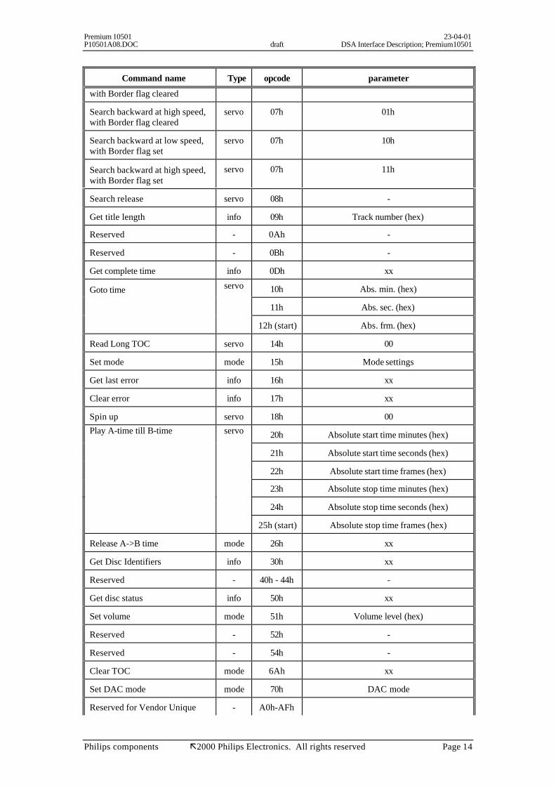
3.4 Command set summary
DSA Command table summary
Command name Type opcode parameter
COMMANDS TO SERVO PROCESSOR
Play title servo 01h Title number (hex)
Stop servo 02h xx
Read TOC servo 03h 00
Pause mode 04h xx
Pause Release mode 05h xx
Search forward at low speed,with Border flag cleared
servo 06h 00h
Search forward at high speed,with Border flag cleared
servo 06h 01h
Search forward at low speed,with Border flag set
servo 06h 10h
Search forward at high speed,with Border flag set
servo 06h 11h
Search backward at low speed, servo 07h 00h
Premium 10501 23-04-01P10501A08.DOC draft DSA Interface Description; Premium10501
Philips components ã2000 Philips Electronics. All rights reserved Page 14
Command name Type opcode parameter
with Border flag cleared
Search backward at high speed,with Border flag cleared
servo 07h 01h
Search backward at low speed,with Border flag set
servo 07h 10h
Search backward at high speed,with Border flag set
servo 07h 11h
Search release servo 08h -
Get title length info 09h Track number (hex)
Reserved - 0Ah -
Reserved - 0Bh -
Get complete time info 0Dh xx
Goto time servo 10h Abs. min. (hex)
11h Abs. sec. (hex)
12h (start) Abs. frm. (hex)
Read Long TOC servo 14h 00
Set mode mode 15h Mode settings
Get last error info 16h xx
Clear error info 17h xx
Spin up servo 18h 00Play A-time till B-time servo 20h Absolute start time minutes (hex)
21h Absolute start time seconds (hex)
22h Absolute start time frames (hex)
23h Absolute stop time minutes (hex)
24h Absolute stop time seconds (hex)
25h (start) Absolute stop time frames (hex)
Release A->B time mode 26h xx
Get Disc Identifiers info 30h xx
Reserved - 40h - 44h -
Get disc status info 50h xx
Set volume mode 51h Volume level (hex)
Reserved - 52h -
Reserved - 54h -
Clear TOC mode 6Ah xx
Set DAC mode mode 70h DAC mode
Reserved for Vendor Unique - A0h-AFh

Premium 10501 23-04-01P10501A08.DOC draft DSA Interface Description; Premium10501
Philips components ã2000 Philips Electronics. All rights reserved Page 15
Command name Type opcode parameter
commands
Reserved - 80h - 83h -
Reserved - C0h - C2h -SERVICE COMMANDS
Service Mode Off servo F0h 00h
Request Servo Version Numberand activate Service Mode
F0h01h
Sledge off F1h 00h
Sledge outside for 300msec F1h 01h
Focus off F2h 00h
Focus on F2h 01h
Turntable motor off F3h 00h
Turntable motor on F3h 01h
Radial off F4h 00h
Radial on F4h 01h
Laser on F5h 00h
Laser off F5h 01h
Diagnostics F6h XX
High gain / Low gain F7h XX
F8h MSB number of groovesJump grooves
F9h(start) LSB number of grooves
RESPONSE COMMANDS FROM SERVO PROCESSOR
Found servo 01h Goto time Found/Paused/Paused Released/Spinned Up/Play A-B Start Found
/Play A-B End Found
Stopped servo 02h xx
Disc status info 03h No disc present / disc presentDisc size 8cm / 12 cm
High/low reflectance discFinalised/unfinalised disc
Error values info 04h Error value
Length of title info09h Lsb byte of seconds of requested title (hex)
0Ah Msb byte of seconds of requested title (hex)Reserved servo 0Bh -
-
Reserved servo 0Ch -
Premium 10501 23-04-01P10501A08.DOC draft DSA Interface Description; Premium10501
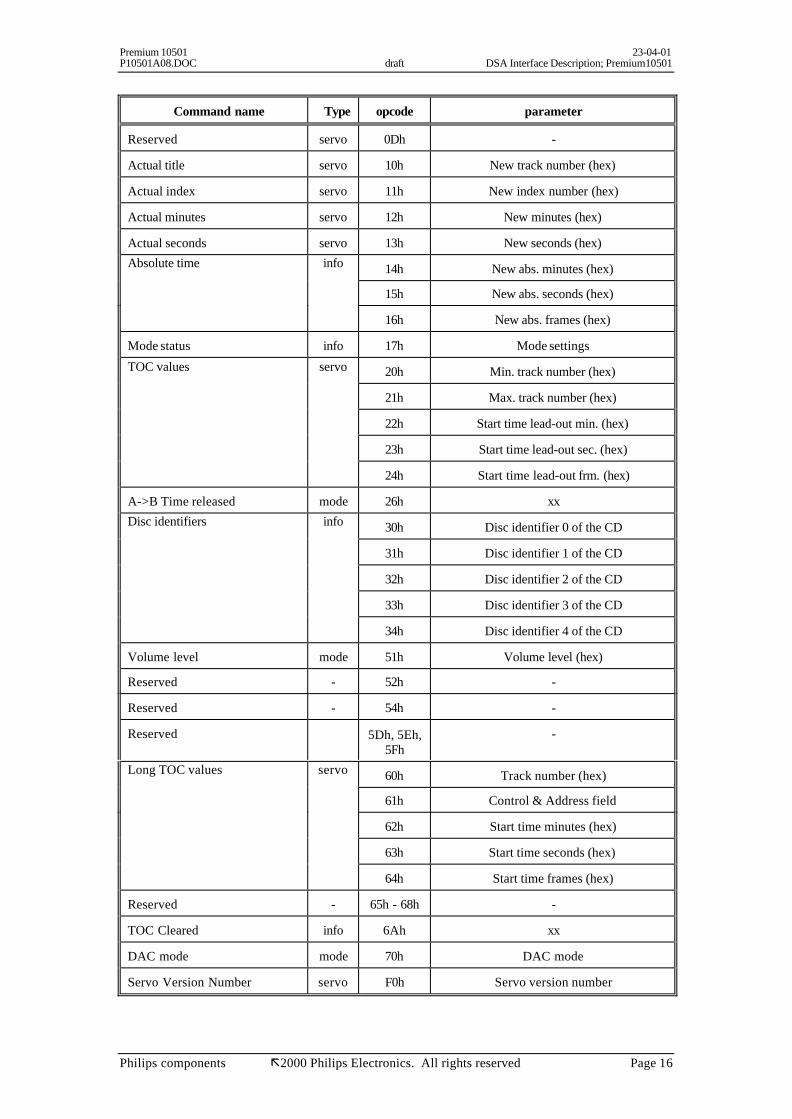
Philips components ã2000 Philips Electronics. All rights reserved Page 16
Command name Type opcode parameter
Reserved servo 0Dh -
Actual title servo 10h New track number (hex)
Actual index servo 11h New index number (hex)
Actual minutes servo 12h New minutes (hex)
Actual seconds servo 13h New seconds (hex)Absolute time info 14h New abs. minutes (hex)
15h New abs. seconds (hex)
16h New abs. frames (hex)
Mode status info 17h Mode settings
TOC values servo 20h Min. track number (hex)
21h Max. track number (hex)
22h Start time lead-out min. (hex)
23h Start time lead-out sec. (hex)
24h Start time lead-out frm. (hex)
A->B Time released mode 26h xxDisc identifiers info 30h Disc identifier 0 of the CD
31h Disc identifier 1 of the CD
32h Disc identifier 2 of the CD
33h Disc identifier 3 of the CD
34h Disc identifier 4 of the CD
Volume level mode 51h Volume level (hex)
Reserved - 52h -
Reserved - 54h -
Reserved 5Dh, 5Eh,5Fh
-
Long TOC values servo 60h Track number (hex)
61h Control & Address field
62h Start time minutes (hex)
63h Start time seconds (hex)
64h Start time frames (hex)
Reserved - 65h - 68h -
TOC Cleared info 6Ah xx
DAC mode mode 70h DAC mode
Servo Version Number servo F0h Servo version number

Premium 10501 23-04-01P10501A08.DOC draft DSA Interface Description; Premium10501
Philips components ã2000 Philips Electronics. All rights reserved Page 17
xx = don't care.

Premium 10501 23-04-01P10501A08.DOC draft DSA Interface Description; Premium10501
Philips components ã2000 Philips Electronics. All rights reserved Page 18
3.5 Play title
This command forces the CD-module to jump to the beginning of the requested track, indicated by 'titlenumber'. If now the internal 'pause mode indicator' is cleared, the CD-module will start tracking,otherwise it goes in pause mode. If the CD-module is in STOP-mode, it starts up first and jump to therequested title.
Remark: The 'pause mode indicator' is an internal flag that indicates weather pause mode hasto be entered after a PLAY-TITLE , GOTO TIME OR PLAY AB command. Thisflag can be set/cleared by PAUSE/PAUSE RELEASE command.
command: Play title 01h / <title number (hex)>
response:
When the start of a title (track) is reached, the CD-module will respond conform the setting ofATTI.
ATTI = 00 The CD-module sends the FOUND command.
ATTI = 10 The CD-module sends the new Title and the actual index, relative time tothe User-processor and afterwards the FOUND command.
ATTI = 01 The CD-module sends the new Title and the actual index, absolute Time tothe User-processor and afterwards the FOUND command.
The ATTI (Actual, Title, Time, Index) value can be set by the SET MODE command, the default valueis 10b (binary).
During Play, the CD-module sends, if selected by ATTI, and when the item changes (TITLE,INDEX, TIME minutes, TIME seconds), the new values to the User-processor.
ATTI = 00 No new Title, Index or Time will be sent if they change.
ATTI = 10 New Title, Index or relative Time (min. or sec) will be sent if they change(only the item that change will be send)
ATTI = 01 New Title, Index or absolute Time (min. or sec) will be sent if they change(only the item that changes will be sent)
When the CD-module runs into the lead-out area, it goes into pause mode and sends the ACTUALTITLE command with value AAh, which indicates lead-out.

Premium 10501 23-04-01P10501A08.DOC draft DSA Interface Description; Premium10501
Philips components ã2000 Philips Electronics. All rights reserved Page 19
response commands:
During play (only when the item changes)
ATTI = 00Found 01h / XX
ATTI = 01Actual title 10h / <new track number>Actual index 11h / <new index number>Actual abs. minutes 14h / <new minutes>Actual abs. seconds 15h / <new seconds>Found 01h / XX
ATTI = 10Actual title 10h / <new track number>Actual index 11h / <new index number>Actual rel. minutes 12h / <new minutes>Actual rel. seconds 13h / <new seconds>Found 01h / XX
The ATTI (Actual, Title, Time, Index) value can be set by the SET MODE command, the default valueis 10b (binary).
Note: Illegal track values while the disc not mounted yet, results that the CD-Module (servo) startstracking from the lead-in area.
3.6 Stop
This command stops playing the disc and brakes. After the STOP-procedure is finished, the CD-module answers with the STOPPED command to the User-processor.This command also clears the internal 'pause mode indicator'.
command: Stop 02h / XX
response command: Stopped 02h / XX

Premium 10501 23-04-01P10501A08.DOC draft DSA Interface Description; Premium10501
Philips components ã2000 Philips Electronics. All rights reserved Page 20
3.7 Read TOC
This command forces the CD-module to read the TOC. After finishing this, the CD-module sends the 5values TITLE MINIMUM, TITLE MAXIMUM and DISC-TIME MIN/SEC/FRM to the User-processor. After reading the TOC, the CD-module goes in pause mode at the beginning of the firsttrack.
Note: This command does not alter the internal 'pause mode indicator'.
command: Read TOC 03h / <00>
response commands: TITLE MINIMUM 20h / <minimum Track number of the CD>TITLE MAXIMUM 21h / <maximum Track number of the CD>DISC-TIME MIN 22h / <maximum time minutes of the CD>DISC-TIME SEC 23h / <maximum time seconds of the CD>DISC-TIME FRM 24h / <maximum time frames of the CD>
3.8 Read Long TOC
This command forces the CD-module to read the TOC. The CD-module passes all track info. Thistrack info consist of TRACK NUMBER, CONTROL & ADDRESS, ABSOLUTE START TIME(min,sec,frm). The CD-module keeps tracking in the TOC (it will jump back into the lead-in if itreaches the program area) until a new servo command is received.
command: Read Long TOC 14h / <00>
response commands: Interpretation of return code depends on <Track number> value
When: 0 <= Track number <= 63h
Track number 60h / <track number>Control & address 61h / <control & address field>Start time minutes 62h / <start time minutes>Start time seconds 63h / <start time seconds>Start time frames 64h / <start time frames>
When: Track number = B0h and address = 5
Track number 60h / < B0h>Control & address 61h / <control & address field ( = y5h)>Start time minutes 62h / <start time minutes next possible program area >Start time seconds 63h / <start time seconds next possible program area >Start time frames 64h / <start time frames next possible program area >
(y = control)
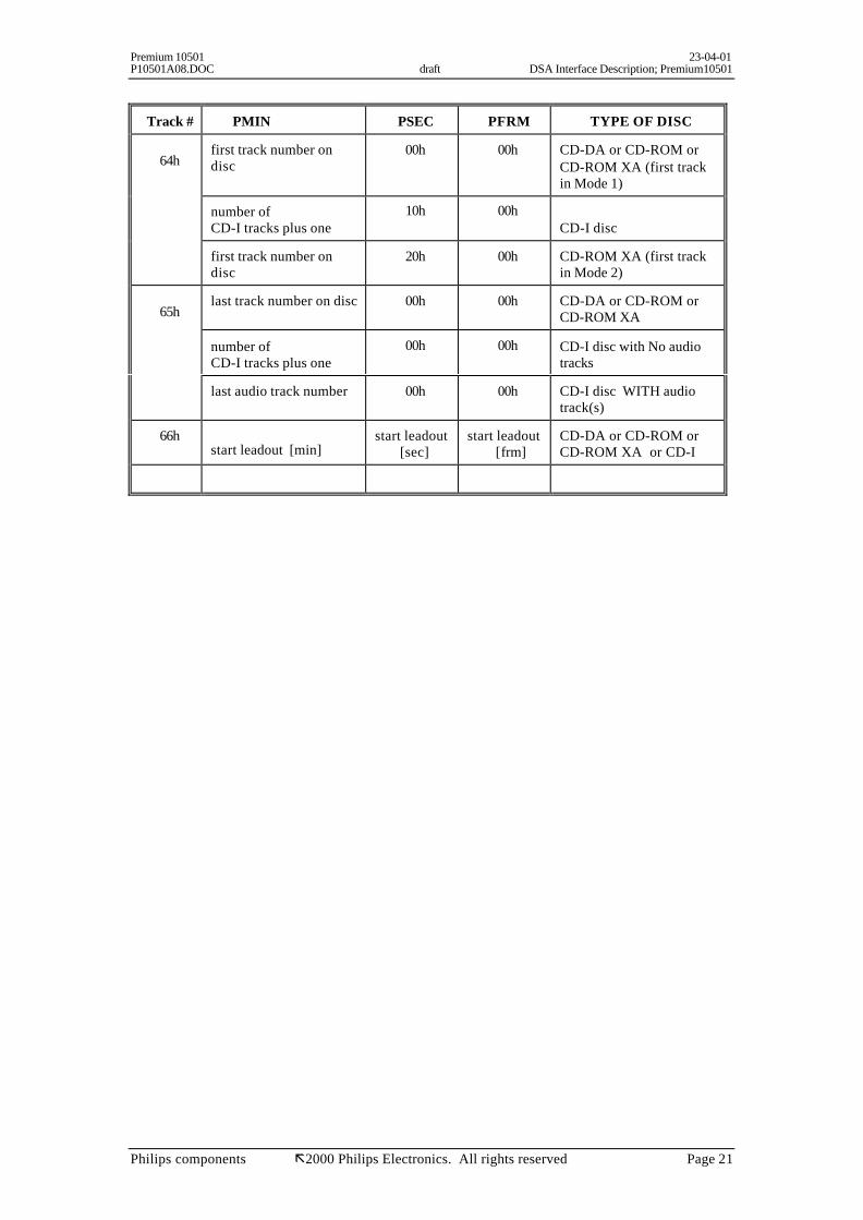
When: Track number = 64h or 65h or 65h and address = 1
Track number 60h / < 64h or 65h or 66h >Control & address 61h / <control & address field ( = y1h)>PMIN 62h / <pmin >PSEC 63h / < psec>PFRAM 64h / < pfrm>
(y = control)
Premium 10501 23-04-01P10501A08.DOC draft DSA Interface Description; Premium10501
Philips components ã2000 Philips Electronics. All rights reserved Page 21
Track # PMIN PSEC PFRM TYPE OF DISC
64hfirst track number ondisc
00h 00h CD-DA or CD-ROM orCD-ROM XA (first trackin Mode 1)
number ofCD-I tracks plus one
10h 00hCD-I disc
first track number ondisc
20h 00h CD-ROM XA (first trackin Mode 2)
65hlast track number on disc 00h 00h CD-DA or CD-ROM or
CD-ROM XA
number ofCD-I tracks plus one
00h 00h CD-I disc with No audiotracks
last audio track number 00h 00h CD-I disc WITH audiotrack(s)
66hstart leadout [min]
start leadout [sec]
start leadout [frm]
CD-DA or CD-ROM orCD-ROM XA or CD-I

Premium 10501 23-04-01P10501A08.DOC draft DSA Interface Description; Premium10501
Philips components ã2000 Philips Electronics. All rights reserved Page 22
3.9 Set Mode
With this command, the CD-module can be set in different modes.After accepting the mode settings, the CD-Module responds with sending the MODE STATUScommand, which reflects the current setting.
When mode = 00h then the current mode setting will be returned.
The default mode values after power up or reset are: speed = 1, mode = Audio (I2S 1 FS), ATTI = 10b(binary).
When the Audio mode is selected the last selected “I2S DAC mode” format will be installed.When the CD-ROM mode is selected the last selected “I2S ROM mode” format will be installed.
The “I2S format” can be set by the 'Set DAC mode” command.
command: Set mode 15h / <mode>
mode bit Mode
2 - 0 this sets the speed001 = normal CD-DA speed, 010 = double speedOther values are reserved.
3 0 = Audio mode, 1 = CD-ROM mode5 - 4 Actual Title, Time, Index (ATTI) setting
00 = no title, index or time send during play modes01 = sending title, index and absolute time (min/sec)10 = sending title, index and relative time (min/sec)11 = reserved
6 'pause at track-end' feature'0: enter pause mode at end of track disabled1: enter pause mode at end of track enabled
7 reserved
command response: Mode status 17h / <mode>
A complete update of track, index, minutes and seconds will follow when ATTI changes from 1 to 2 orvice versa.
The bit definitions for <mode> are the same as for the SET MODE command.
When the 'pause at track-end' feature is enabled (bit 6 = '1') the CD-Module will enters pause mo de atthe end of each track. Also during PLAY A-B TIME. Therefore it's recommended that during play A-Btime the 'pause at track-end' is disabled.The 'pause at track-end' feature is not valid for the search function, this means; when searching withborder flag cleared while 'pause at track end' is enabled, the search will NOT stop at track-end!The 'pause at track-end' feature can be used to play just one track.The response, when reaching track-end (when 'stop at track-end' feature (bit 6 = '1') is enabled) will bethe ACTUAL TRACK update with the next track value, so;
Actual title 10h / <next track number>
Note: When the 'pause at track end' feature (bit 6 = '1') is enabled, the 'Actual title' response isalways send, even when ATTI = 0.

Premium 10501 23-04-01P10501A08.DOC draft DSA Interface Description; Premium10501
Philips components ã2000 Philips Electronics. All rights reserved Page 23
3.10 Get last error.
This command request the last encountered error. The CD-module responds with sending the ERRORVALUE command. The 'last error' will only be cleared by the CLEAR ERROR command.
command: Get last error 16h / XX
response command: Error value 04h / <error value>
3.11 Clear error.
This command clears the latest error code. The CD-module respond with sending the ERRORVALUES command with error code set to zero.
command: Clear error 17h / XX
response command: Error value 04h / <00>
3.12 Spin up
This command is used to spin up (mount the disc) it reads the TOC and seeks to the beginning (= thestart time) of the first track in that program area and goes in 'pause mode'. If the disc is already spunup, the CD-module will treat this command as a seek to the start time of first track.When the SPIN UP command is ready, the CD-module sends the FOUND command.
Note: This command does not alter the internal 'pause mode indicator'.
command: Spin up 18h / <00>
response command: Found 01h / 43h
3.13 Pause
This command forces the CD-module to go into PAUSE mode (if tracking) and sets the internal 'pausemode indicator'. Setting the 'pause mode indicator' is always possible.This command responds always with 'FOUND'.Pause is released by the PAUSE RELEASE or STOP commands.When the 'pause mode indicator' is set, the CD-module will always enter the pause mode after a jump(PLAY TRACK, GOTO TIME, PLAY A->B TIME).
command: Pause 04h / XX
response command: Found 01h /41h

Premium 10501 23-04-01P10501A08.DOC draft DSA Interface Description; Premium10501
Philips components ã2000 Philips Electronics. All rights reserved Page 24
3.14 Pause Release
This command releases the PAUSE mode (if pausing) and clears the 'pause mode indicator'. Duringtracking any change in actual title, time, index (if selected by ATTI) will be sent by their correspondingcommands.
command: Pause release 05h / XX
response command: Found 01h/ 42h
3.15 Search Forward/Backward
When the CD-module is in play mode, these commands start the Search Forward/Backward.At low speed the music is attenuated by -12dB, at high speed the music is muted.
The Border flag controls the behaviour of SEARCH on the end of a title: If the Border flag is set, it isnot possible to leave the actual title with SEARCH, the CD-module stops searching ±5 seconds beforethe end of the title or at the beginning of the title.If the Border flag is not set then the whole Disc can be SEARCHED.
The Search function is released by the SEARCH RELEASE command.
command: Search forward at low speed, with Border flag cleared 06h / 00Search forward at high speed, with Border flag cleared 06h / 01Search forward at low speed, with Border flag set 06h / 10Search forward at high speed, with Border flag set 06h / 11Search backward at low speed, with Border flag cleared 07h / 00Search backward at high speed, with Border flag cleared 07h / 01Search backward at low speed, with Border flag set 07h / 10Search backward at high speed, with Border flag set 07h / 11
response command: no command
Note:It’s recommended when searching with border flag set, that the 'pause at track-end' feature(selectable in SET MODE) is disabled.
3.16 Search Release
This command simply releases SEARCH.
command: Search Release 08h / XX
response command: no command

Premium 10501 23-04-01P10501A08.DOC draft DSA Interface Description; Premium10501
Philips components ã2000 Philips Electronics. All rights reserved Page 25
3.17 Get title length
This command is used to get the time of a specified title (1 - 20) only from the first PROGRAM AREAon the disc (used for EDIT, PROGRAM, ...). The CD-module sends the time in seconds (high and lowbyte) back to the User-processor (which must recognise the last requested title number).
command: Get title length 09h / <track number>
response command: Length of title (lsb) 09h / <Low byte of seconds of requested title>Length of title (msb) 0Ah / <High byte of seconds of requested title>
3.18 Get complete time
This command forces the CD-module to send the next ABSOLUTE DISC TIME to the User-processorwhen the disc is turning.
command: Get complete time 0Dh / XX
response commands:
Absolute time minutes 14h / <new minutes>Absolute time seconds 15h / <new seconds>Absolute time frames 16h / <new frames>
3.19 Goto time
This command forces the CD-module to jump to the requested absolute time location. If now theinternal 'pause mode indicator' is cleared, the CD-module will start tracking, otherwise it goes in pausemode.
The jump to the desired time position starts after receiving the FRAMES. When the requested timeposition is reached, ' Found ' is sent.
command: Goto time min. 10h / <absolute minutes> [ 0- 63h ]Goto time sec. 11h / <absolute seconds> [ 0-3Bh ]Goto time frm. 12h / <absolute frames > (starts execution) [ 0-4Ah ]
response command: Found 01h/40h
If the absolute time is invalid, the CD-module can respond with the ERROR VALUE command witherror value set to 'illegal command'.
The absolute time must be greater than or equal to 0 : 02 : 00 (min, sec, frm) and less than or equal tolast the leadout starting time.
Premium 10501 23-04-01P10501A08.DOC draft DSA Interface Description; Premium10501
Philips components ã2000 Philips Electronics. All rights reserved Page 26
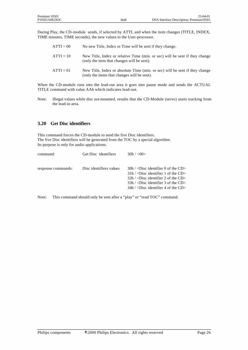
During Play, the CD-module sends, if selected by ATTI, and when the item changes (TITLE, INDEX,TIME minutes, TIME seconds), the new values to the User-processor.
ATTI = 00 No new Title, Index or Time will be sent if they change.
ATTI = 10 New Title, Index or relative Time (min. or sec) will be sent if they change(only the item that changes will be sent).
ATTI = 01 New Title, Index or absolute Time (min. or sec) will be sent if they change(only the items that changes will be sent).
When the CD-module runs into the lead-out area it goes into pause mode and sends the ACTUALTITLE command with value AAh which indicates lead-out.
Note: Illegal values while disc not mounted, results that the CD-Module (servo) starts tracking fromthe lead-in area.
3.20 Get Disc identifiers
This command forces the CD-module to send the five Disc identifiers.The five Disc identifiers will be generated from the TOC by a special algorithm.Its purpose is only for audio applications.
command: Get Disc identifiers 30h / <00>
response commands: Disc identifiers values 30h / <Disc identifier 0 of the CD>31h / <Disc identifier 1 of the CD>32h / <Disc identifier 2 of the CD>
33h / <Disc identifier 3 of the CD> 34h / <Disc identifier 4 of the CD>
Note: This command should only be sent after a “play” or “read TOC” command.

Premium 10501 23-04-01P10501A08.DOC draft DSA Interface Description; Premium10501
Philips components ã2000 Philips Electronics. All rights reserved Page 27
3.21 Play A-time till B-time
This command forces the CD-module to play from the requested absolute start time (A-time) till endtime (B-time). If the internal 'pause mode indicator' is cleared, the CD-module will start tracking fromA-time, otherwise it goes in pause mode at A-time.
The jump to the desired A-time starts after receiving the STOP FRAMES. When reached, the CD-module sends ACTUAL TITLE, ACTUAL TIME = the A-time (min/sec), if selected by ATTI, andACTUAL INDEX, then it terminates always with the FOUND.When the end time (B-time) is reached, the CD-module enters pause mode and sends the actual Title,index, minutes and seconds to the User processor.
A-time and B-time must be in one program area and B-time must be greater than or equal to A-time.
During Play A-time to B-time, the CD-module can send, if selected by ATTI, when something changes(TITLE, INDEX, TIME minutes, TIME seconds), the new values to the User-processor.
ATTI = 00 No new Title, Index or Time will be sent if they change.
ATTI = 10 New Title, Index or relative Time (min. or sec) will be sent if it changes(only the item that changes will be sent)
ATTI = 01 New Title, Index or absolute Time (min. or sec) will be sent if it changes(only the item that changes will be sent)
If any error is encountered, the command ERROR VALUES is sent from the CD-module and thePLAY A-TIME TILL B-TIME command is terminated (pause mode).
command: 20h / <absolute start time minutes>` 21h / <absolute start time seconds>
22h / <absolute start time frames>23h / <absolute stop time minutes>24h / <absolute stop time seconds>25h / <absolute stop time frames> (start execution)
Premium 10501 23-04-01P10501A08.DOC draft DSA Interface Description; Premium10501
Philips components ã2000 Philips Electronics. All rights reserved Page 28
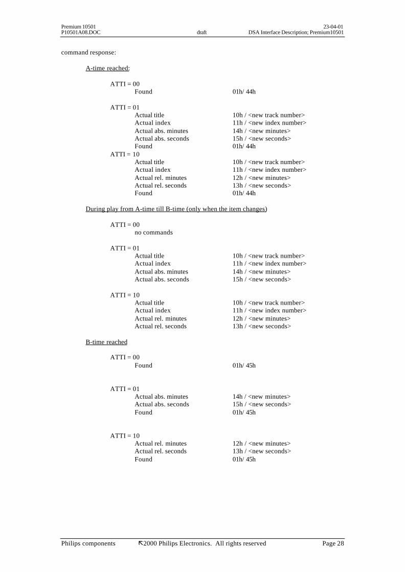
command response:
A-time reached:
ATTI = 00Found 01h/ 44h
ATTI = 01Actual title 10h / <new track number>Actual index 11h / <new index number>Actual abs. minutes 14h / <new minutes>Actual abs. seconds 15h / <new seconds>Found 01h/ 44h
ATTI = 10Actual title 10h / <new track number>Actual index 11h / <new index number>Actual rel. minutes 12h / <new minutes>Actual rel. seconds 13h / <new seconds>Found 01h/ 44h
During play from A-time till B-time (only when the item changes)
ATTI = 00no commands
ATTI = 01Actual title 10h / <new track number>Actual index 11h / <new index number>Actual abs. minutes 14h / <new minutes>Actual abs. seconds 15h / <new seconds>
ATTI = 10Actual title 10h / <new track number>Actual index 11h / <new index number>Actual rel. minutes 12h / <new minutes>Actual rel. seconds 13h / <new seconds>
B-time reached
ATTI = 00Found 01h/ 45h
ATTI = 01Actual abs. minutes 14h / <new minutes>Actual abs. seconds 15h / <new seconds>Found 01h/ 45h
ATTI = 10Actual rel. minutes 12h / <new minutes>Actual rel. seconds 13h / <new seconds>Found 01h/ 45h

Premium 10501 23-04-01P10501A08.DOC draft DSA Interface Description; Premium10501
Philips components ã2000 Philips Electronics. All rights reserved Page 29
The ATTI (Actual Title, Time and Index) value can be set by the SET MODE command, the defaultvalue is 10b (binary).
Note: Illegal values while disc not mounted, results that the CD-Module (servo) starts tracking fromthe lead-in area.
3.22 Release A->B time
This command releases the A time till B time feature. Only checking on B-time will be disabled.When the CD-Module was tracking, it keeps tracking.
command: Release A->B time 26h / XX
command response: A->B time released 26h / XX
3.23 Get Disc Status
This command forces the CD-module to send the current disc status.The CD-module responds with sending the DISC STATUS command.
command: Get disc status 50h / XX
command response: disc status 03h / <disc status>
bit disc status 0 0 = no disc present or TOC('s) not read.
1 = disc present and TOC('s) read. 1 for Jukebox application always zero 0 2 this bit is only valid when bit 0 is set
0 = disc size is 8 cm1 = disc size is 12 cm
3 this bit is only valid when bit 0 is set0 = high reflectance disc ( CD-DA / CD-R )1 = low reflectance disc ( CD-RW )
4 this bit is only valid when bit 0 is set0 = non-finalised disc1 = finalised disc
5-7 reserved
3.24 Set Volume
With this command the audio volume can be controlled (only in audio mode).The volume level is determined by the value (linear scale) with a range from 0 (= mute) till 255 (fullscale) with a resolution of 2.
command: Set volume 51h / <volu me value>
volume value meaning0 mute1 - 254 fade255 full scale
Premium 10501 23-04-01P10501A08.DOC draft DSA Interface Description; Premium10501
Philips components ã2000 Philips Electronics. All rights reserved Page 30
response command: Volume value 51h / <volume value>

Premium 10501 23-04-01P10501A08.DOC draft DSA Interface Description; Premium10501
Philips components ã2000 Philips Electronics. All rights reserved Page 31
3.25 Clear TOC
This command clears the TOC info stored in ram. This command is only allowed in stop mode.This command must be given by each disc change.
command: Clear TOC 6Ah / <xx >
response commands: TOC cleared 6Ah / <xx>
3.26 Set DAC mode (I2S output format)
This command sets the I2S output format. The command will be executed directly for the modeselected previously by 'SET MODE' command, otherwise it will be saved internally.
command: Set DAC mode 70h / <I2S mode>
response command: DAC mode 70h / <I2S mode>
<I2Smode>
I2S format mode
see SET MODE command
0 reserved
1 I2S - FS mode (default) DAC mode
2 I2S - 2 FS mode DAC mode
3 I2S - 4 FS mode DAC mode
4 Sony 16 bit FS DAC mode
5 Sony 16 bit 2 FS DAC mode
6 Sony 16 bit 4 FS DAC mode
7 Sony 18 bit FS DAC mode
8 Sony 18 bit 2 FS DAC mode
9 Sony 18 bit 4 FS DAC mode
81 I2S - CD-ROM mode CD-ROM mode
82 EIAJ CD-ROM mode CD-ROM mode

Premium 10501 23-04-01P10501A08.DOC draft DSA Interface Description; Premium10501
Philips components ã2000 Philips Electronics. All rights reserved Page 32
3.27 Service control commands
These commands control the Service mode of the CD-module. The service mode is entered byrequesting the servo version number. Only in the service mode, it is possible to give additionalcommands such as radial, sledge, focus or turntable motor on/off. The other commands such as playtrack are not valid. The Service Mode is deactivated by the Service Mode Off command.However there is no check on the correct usage of these service commands. The set should be in stopmode before trying any service commands. Also the order in which the commands are given, is notprotected. For example, the radial should not be activated when the focus is off. A safe order would be:first put the focus on, then the disc motor and then the close radial loop.
commands:Service Mode Off F0h / 00Request Servo Version Number and activate Service Mode* F0h / 01Sledge off F1h / 00Sledge outside for 300msec F1h / 01Focus off F2h / 00Focus on F2h / 01Turntable motor off F3h / 00Turntable motor on F3h / 01Radial off F4h / 00Radial on F4h / 01Laser off F5h / 00Laser on F5h / 01Diagnostics command F6h / xxHigh gain (Trigenta) F7h / 00Low gain (Trigenta) F7h / 01
* only these commands give the response command(s), listed below
response commands:
Response on the REQUEST SERVO VERSION NUMBER command
Servo Version Number F0h / <Servo VersionNumber>
Every service command will be explained below.
- Service Mode Off
This command switches the service mode off. If the service mode was activated, all servos areswitched off.
- Request Servo Version Number and activate Service Mode
With this command the CD-module will enter the 'service mode'. It will respond with returning theServo Version Number.The sledge will be positioned at the inner most position.

Premium 10501 23-04-01P10501A08.DOC draft DSA Interface Description; Premium10501
Philips components ã2000 Philips Electronics. All rights reserved Page 33
- Sledge off
This command will stop moving the sledge. If it is stopped, the sledge will be positioned at the innermost position.
- Sledge outside for 300msec
This command forces the sledge to move outside for 300msec. After the 300msec, the sledge will bepositioned back at the inner most position.
- Focus off
This command will switch off the focus loop. Because the focus loop has to be switched off also theradial loop, the spindle motor and the laser will be switched off.
- Focus on
This command puts the laser in focus. If the laser was off, it will be switched on.
- Turntable motor off
This command switches the spindle motor off. Because the spindle motor has to be switched off, alsothe radial loop will be switched off.
- Turntable motor on
This command will switch the spindle motor on. To achieve this, the laser will be switched on, alsofocus has to be found (disc present!).
- Radial off
This command will switch off the radial loop.
- Radial on
This command will switch on the radial loop. To achieve this, the laser will be switched on, focus hasto be found (disc present!) and the spindle motor has to be turned on.
- Laser off
This command switches the laser off. Also the radial loop, the spindle motor, and the focus loop will beswitched off.
- Laser on
This command will switch on the laser.
- Diagnostics command

Premium 10501 23-04-01P10501A08.DOC draft DSA Interface Description; Premium10501
Philips components ã2000 Philips Electronics. All rights reserved Page 34
This is a very dangerous command to use. It is possible to alter every CD10 setting, resulting in afailure of the CDM. You can always reset to the initial values via the calibrate switch on the PCB, orby power down of the CDM. Always use this command or the calibrate swicth during STOP mode,not during PLAY !
DSA command : 0F6HDSA value : xy
Where x is the address nibble and y the data nibble of the decoder register.
Purpose : To write the CD10 decoder registers 0 to F.
Examples :
• EBU output mode change (register A) :
1. Goto service mode.2. 0F6H 0AAH EBU mode - flags on3. 0F6H 0A2H EBU mode - flags off4. Goto normal mode.
• Iref change (shadow registers A and C) :
1. Goto service mode.2. 0F6H 0FDH Enable shadow registers3. 0F6H 0AxH Set Iref D1D44. 0F6H 0CxH Set Iref R1R25. 0F6H 0FCH Disable shadow registers6. Goto normal mode.
• Switch internal DAC on/off (shadow register 7) :
1. Goto service mode2. 0F6H 0FDH Enable shadow registers3. 0F6H 74H Disable internal DAC4. 0F6H 77H Enable internal DAC5. 0F6H 0FCH Disable shadow registers6. Goto normal mode.
- High/Low gain command
DSA command : 0F7HDSA value : 0 Gain switched for reading CD-RW
1 Gain switched for reading CD-DA and CD-R
Purpose : To be able to read also CD-RW discs.
- Jump grooves command
DSA command : 0F8H + 0F9HDSA value : MSB most significant byte for the number of grooves
LSB least significant byte for the number of grooves
Purpose : To be able to move the sledge for a number of grooves
3.28 Error handing
Premium 10501 23-04-01P10501A08.DOC draft DSA Interface Description; Premium10501
Philips components ã2000 Philips Electronics. All rights reserved Page 35
Whenever an error is detected during the execution of a command, the CD-module sends aftercommand execution the ERROR VALUE command to the User-processor.If an error is encountered, the command in execution will be terminated.
Remark:Because error codes are given only after command execution, an error will not be stated during “play”
To control errors during “play”, send regularly:
>: GET Complete time, command 0Dh/00<: wait for the DSA command containing the minutes, seconds, frameThis time-code received must be higher than the previous one (logical during play).
It is also possible to use the “actual updates” for this false detection.When the updates of the seconds are not appearing (for more than 1 second) or the new timecode is notsuccessive, then an unrecoverable error situation has been detected.
The recovery could be handled by the DSA-command “Goto Time” to the last received timecode.
3.29 Error code table
Error code(dec, hex)
Meaning
0 No error
2 Focus error, or no disc
7 Subcode error, no valid subcode
8 TOC error, out of lead-in area while reading TOC
10, 0Ah Radial error
12, 0Ch Fatal sledge error
13, 0Dh Turn table motor error
48, 30h Emergency Stop
31, 1Fh Search time out
32, 20h Search binary error
33, 21h Search index error
34, 22h Search time error
40, 28h Illegal command
41, 29h Illegal value
42, 2Ah Illegal time value
43, 2Bh Communication error
44, 2Ch Reserved
45, 2Dh HF Detector Error
4. Emergency stop
With the LASER OFF hardware line an emergency stop can be achieved.

Premium 10501 23-04-01P10501A08.DOC draft DSA Interface Description; Premium10501
Philips components ã2000 Philips Electronics. All rights reserved Page 36
When making the LASER OFF line is grounded, the laser will be switched off immediate. Also, allservo's wills become inactive.
When the emergency stop becomes active, the DSA command ERROR-VALUE with error-value'EMERGENCY STOP' will be sent from CD-Module to User Processor.
5. Test Loops command set
Following test loops are available :
1. Play Track 1 & 24 for 10 seconds per track2. Play Track random for 5 seconds per track3. Play disc for until lead-out4. Goto Time random
Enter following DSA commands :
Starting a test loop :
A6h x Start testloop number xA7h yyh number of loops MSBA8h zzh number of loops LSB
Testloop x is started for yyzzh times.If yy and zz are 00, the number of testloops is infinite.
Stopping a test loop :
Give the DSA command STOP.When an error occurred during a test loop, the loop is stopped automatically.
Asking for the number of loops done :
A5h xx


![Original Article TTwo cases of disseminated superfiwo ... superficial actinic porokeratosis (DSAP) was first described by Chernosky and Freeman [1]. Clinically, DSAP is characterized](https://static.fdocuments.us/doc/165x107/5e97bf9da930ec75a20081e0/original-article-ttwo-cases-of-disseminated-superfiwo-superficial-actinic-porokeratosis.jpg)