DS7400Xi (version 3+) Security System User’s...
48
DS7400Xi (version 3+) Security System User’s Guide An instruction guide for your alarm system when used with a DS7447/DS7447E or DS7445/DS7445i keypad Alpha “English Display” Keypad LED Keypad DS7447/DS7447E 1 2 3 4 5 6 7 8 9 0 * # On No Entry System Reset Bypass Only Perimeter Off TEST WEEKLY 1 2 3 4 5 6 7 8 9 10 11 1213 14 15 16 Armed Status Power Fire Perimeter Supervisory Bell Silenced Trouble 1 2 3 4 5 6 7 8 9 0 * # On No Entry System Reset Bypass Only Perimeter Off TEST WEEKLY Armed Status Power Fire DS7445/DS7445i
Transcript of DS7400Xi (version 3+) Security System User’s...

DS7400Xi (version 3+) Security SystemUser’s Guide
An instruction guide for your alarm systemwhen used with a DS7447/DS7447E or DS7445/DS7445i keypad
Alpha “English Display” KeypadLED KeypadDS7447/DS7447E
1 2 3
4 5 6
7 8 9
0* #
On
NoEntry
SystemReset
Bypass
OnlyPerimeter
Off
TEST WEEKLY
1 2 3 4 5 6 7 8
9 10 11 12 13 14 15 16
Armed
Status
Power
Fire
Perimeter
Supervisory
Bell Silenced
Trouble
1 2 3
4 5 6
7 8 9
0* #
On
NoEntry
SystemReset
Bypass
OnlyPerimeter
Off
TEST WEEKLY
Armed
Status
Power
Fire
DS7445/DS7445i

- 2 -
Congratulations on the installation of your new security system. No other investment can provide such peace of mind. Welcometo the DS7400Xi intrusion/fire control system. Since each installation is unique, yours will contain some, but not necessarily all ofthe features mentioned in this guide.
A security system usually consists of:
• A Control Panel: The control panel is the center of your intrusion/fire alarm system. It supports such vital functionsas receiving trouble and alarm signals from detectors, the sounding of bells and/or sirens, andcommunicating with your alarm monitoring company.
• Command Control Stations (Keypads): The keypad is where you interact with the system. The keypad displayscritical information concerning the operation of your alarm system, plus it allows you to initiatecommands such as arming and disarming.
• Protected Zones: Your security system may contain protected windows and doors (perimeter zones), plus variousinternal sensors. Your control panel separates perimeter zones from interior protection zones.Specific protection devices may include:
• Glass Breakage sensors: Devices that detect the sound of breaking glass.
• Interior Motion sensors: Electronic sensors (i.e. passive infrared) that detectmovement within an interior zone.
• Magnetic Contacts: Switches used to detect the opening of doors or windows.
• Smoke Detectors: Devices that detect products of combustion.
This system includes a telephone line seizure feature. The system may be programmed to communicate with a centralmonitoring station to report system events. You will not be able to use your phone while the system is communicating withthe central monitoring station. In the unlikely event that the central station is not able to receive the report, your phone maybe unavailable for up to 20 minutes while the panel makes additional communication attempts.
System Overview

- 3 -
System Overview ................................................................. 2Table of Contents ................................................................. 3Important .............................................................................. 3Day to Day Operations ......................................................... 4
Understanding the DS7447/DS7447E and DS7445/DS7445i Keypads ..................................................... 4
Turning ON (arming) your System....................................... 6Quick Arming your System ................................................. 8Turning OFF (disarming) your System / Silencing Alarms 9Force Arming your System ............................................... 10Zone Bypass ...................................................................... 11Automatic Arming .............................................................. 12Automatic Disarming ......................................................... 13Delaying Automatic Arming ............................................... 14Delayed Arming .................................................................. 15Chime Mode ....................................................................... 16Access Control ................................................................... 17Changing the Date ............................................................. 18Changing the Expiration Date (for Temporary PINs) ........ 19Changing the Time ............................................................. 20
Emergency Procedures ...................................................... 21Identifying Alarm Sounds .................................................. 21Fire Alarms ......................................................................... 21Turning OFF (disarming) your System under Duress ...... 22Emergency Keypad Alarms / Silencing Alarms ............... 23Fire Reset / Fire Trouble .................................................... 24
Fire Safety ........................................................................... 25If Installed in Family Residences ...................................... 25
Installation Considerations ................................................ 26Personal Identification Numbers ...................................... 27
General Information ........................................................... 27Change a PIN. .................................................................... 28PIN Authority Levels .......................................................... 29
Error Displays ..................................................................... 30System Faults .................................................................... 31
Testing your System .......................................................... 32Zone Test. ........................................................................... 32Battery Test. ....................................................................... 33Communicator Test. ........................................................... 34Fire WalkTest. ..................................................................... 35
Event History Readback ..................................................... 36The Master Keypad
General Information ............................................................ 37Master Keypad Displays ..................................................... 38Arming from the Master Keypad ......................................... 39Disarming from the Master Keypad .................................... 40Single Partition Mode ......................................................... 41
Glossary .............................................................................. 42Index .................................................................................... 44Quick Reference Guide ..................................................... 45System Features Reference Guide................................... 47
Table of Contents
Your system may or may not be monitored by an alarm monitoringservice. If it is not monitored, it is vital to understand the following:
• Alarms sound only at your location.• When an alarm is sounded, no signals are sent out.• Duress and other silent alarms are disabled.• Emergency alarms sound only at your location.
Important

- 4 -
This chart will help you understand what each Light/LEDon a Standard keypad represents.
(For Master keypad operation, see page 37.)
The DS7447/DS7447E is an alpha-numeric LCD keypad.The DS7445/DS7445i is an LED keypad; its LEDs 1-8 repre-
sent the first 8 zones of the system.
Both display information on various control panel functions.A built-in sounder is used to annunciate keystroke entries and
functions as an interior warning device.
Day to Day Operations
Understanding the DS7447/DS7447E and DS7445/DS7445i Keypads
continued on next page
Light Off Flashing On
Armed(red)
Status(green)
Power(green)
Fire(red)
The control panel is disarmed.
One or more zones arenot ready to arm.
The control panel has lost allpower. There is no AC or
battery.
There are no fire alarms.
An exit delay is in progress oran alarm has occurred.
One or more zones arebypassed.
Control panel problems exist.See Error Displays.
A fire zone is in alarm.
The control panel is armed,and no alarms have occurred.
All zones are ready to arm.
The control panel is in normal operation.It is running on AC power with no problems.
A fire trouble condition exists.
DS7447/DS7447E
1 2 3
4 5 6
7 8 9
0* #
On
NoEntry
SystemReset
Bypass
OnlyPerimeter
Off
TEST WEEKLY
1 2 3 4 5 6 7 8
9 10 11 12 13 14 15 16
Armed
Status
Power
Fire
Perimeter
Supervisory
Bell Silenced
Trouble
1 2 3
4 5 6
7 8 9
0* #
On
NoEntry
SystemReset
Bypass
OnlyPerimeter
Off
TEST WEEKLY
Armed
Status
Power
Fire
DS7445/DS7445E

- 5 -
Volume Control: The keypad sounder volume can be adjusted using the [1] and [4] keys along with the [*] key.- Hold the [*] key while pressing the [1] key to increase the volume or the [4] key to decrease the volume.
Backlight Control (DS7447/DS7447E Only): The display backlight intensity can be adjusted using the [3] and [6] keys along withthe [*] key.- Hold the [*] key while pressing the [3] key to increase the brightness or the [6] key to decrease the brightness.
Note: After the backlight and volume are adjusted you must arm and disarm the system once to store this information in thecontrol panel. If power is disconnected before the panel is armed, the backlight and volume levels will return to thedefault settings.
Understanding the DS7447/DS7447E and DS7445/DS7445i Keypads (continued)
These Lights Present on the DS7445/DS7445E Only:
Light Off Flashing On
Perimeter(yellow)
Supervisory(yellow)
BellSilenced
(red)
Trouble(yellow)
Panel is disarmed oris not armed Perimeter.
There are no supervisoryalarms present.
The bells do not need to beor have not been silenced.
There are no troubleconditions.
This Light will not flash.
A supervisory condition exists.
This Light will not flash.
This Light will not flash.
The perimeter is armed.
This Light will not turn on steady.
There has been a Fire alarm and the bellshave been silenced. To clear, enter the
Fire Reset command: [PIN] + [System Reset].
A trouble condition exists.
LEDs 1-8(red)
There are no zone alarms. A zone (1-8) has beenalarmed.
A zone (1-8) is Not Ready to Arm, orif a fire zone, a trouble condition exists.

- 6 -
This chart explains the five normal ways to arm the system from a Standard keypad. (For a Master keypad see page 37.)
The green Status Light must be on steady and the display* must read “Ready to Arm” in order to arm the system with one ofthese commands. If the green Status Light is not on, or if the display* is reading “Not Ready,”
see Force Arming or Zone Bypass for other ways to arm the system.
Note: In commercial burglar alarm applications for U.L. Listed systems, a ring-back indication and belltest should be heard after arming (closing). If not heard, call for service.
Turning ON (arming) your System
continued on next page
* = DS7447/DS7447E only** = DS7445/DS7445i only
Type of Arming Desired CommandSequence What will Happen What to Do
Normal Arming
No one left on thepremises.
An entry/exit delayis in effect.
[PIN] + [On]
The red Armed Light will begin to flash.“Armed” will be displayed.*“Exit Now” will be displayed during the exit delayinterval.*A single beep will sound.The red Armed Light will turn on steady after the exitdelay expires.
Exit during the exitdelay interval.
Perimeter Arming
Someone still on thepremises.
There is NO entry delayin effect.
[PIN] +[No Entry] +
[Perimeter Only]
The red Armed Light will begin to flash.“Perimeter Inst.” will be displayed.*“Exit Now” will be displayed during the exit delayinterval.*The green Status Light will turn on steady.A single beep will sound.Only exterior protection zones will be armed.The red Armed Light will turn on steady after the exitdelay expires.The yellow Perimeter Light will turn on steady.**
Move freely aroundthe interior.

- 7 -
Note: In commercial burglar alarm applications for U.L. Listed systems, a ring-back indicationand bell test should be heard after arming (closing). If not heard, call for service.
* = DS7447/DS7447E only** = DS7445/DS7445i only
Type of Arming Desired CommandSequence What will Happen What to Do
Move freelyaround the
interior.
Perimeter Arming
Someone still on thepremises.
The entry/exit delayis in effect.
[PIN] +[Perimeter Only]
Exit during theexit delayinterval.
The red Armed Light will begin to flash.“Perimeter On” will be displayed.*“Exit Now” will be displayed during the exit delay interval.*The green Status Light will turn on steady.A single beep will sound.Only exterior protection zones will be armed.The red Armed Light will turn on steady after the exit delayexpires.The yellow Perimeter Light will turn on steady .**
Exit during theexit delay interval.
CAUTION:Violating any zoneafter the exit delay
will cause aninstant alarm.
[PIN] + [#] + [4]
[PIN] + [No Entry]
+ [On]
Custom Arming(If programmed)
Ask your installing companyto explain the type of armingthat occurs when using this
command.
Maximum SecurityArming
No one left on the premises.
There is NO entry delayin effect. An alarm WILL occur
upon entry.
The red Armed Light will begin to flash.“On Partial” will be displayed.*“Exit Now” will be displayed during the exit delay interval.*The green Status Light will turn on steady.A single beep will sound.The red Armed Light will turn on steady after the exit delayexpires.
The red Armed Light will begin to flash.“Armed Instant” will be displayed.*“Exit Now” will be displayed during the exit delay interval.*A single beep will sound.The red Armed Light will turn on steady after the exit delayexpires.

- 8 -
This chart explains four ways to quick arm the system from a Standard keypad.
If Quick Arming is not used, a PIN must be entered at the beginning of all arming command sequences.
When Quick Arming is used, the following short-cuts are available:
Note: Quick Arming is not available from a Master keypad.
Quick Arming your System
Type of ArmingQuick Arming Command Sequence
[#] + [On] Normal Arming
[#] + [No Entry] + [Perimeter Only] Perimeter Arming - no entry delay
[#] + [Perimeter Only] Perimeter Arming - entry/exit delay
[#] + [No Entry] + [On] Maximum Security Arming

- 9 -
This chart explains proper procedures for disarming and/or silencing alarms from a Standard keypad.(To disarm from a Master keypad, see page 40.)
Please read the section about Emergency Procedures prior to being confronted with an emergency event.
If you have entered the building through a perimeter door, you may hear a steady pre-alert tone from the keypads.If so, disarm according to the chart below.
WARNING: If the bells and sirens are on and/or the red Armed Light is flashing with the DS7447/DS7447E display reading“Zone Alarm,” then the keypad is signaling that an alarm has occurred sometime before your arrival. The keypad will also issuea pulsed tone during the entry delay instead of the usual steady tone. If the alarm has not been previously investigated, do not
enter the building unless accompanied by the appropriate Emergency Services’ personnel.
Action Desired Command Sequence What Will Happen
Disarming the System [PIN] + [Off] The red Armed Light will turn off. Pre-alert sounders will silence.
Silencing Alarms [PIN] + [Off]
Alarms in progress will silence. When silencing a fire alarm, the
DS7447/DS7447E will display “Sounder Silenced” and the DS7445/DS7445i will
light the Bell Silenced LED until the system has been reset.
When in Commercial Fire Mode,entering your [PIN] followed by the [#] key a second time
allows you to locate the fire zone number(s) that is (are) in alarm.
Turning OFF (disarming) your System / Silencing Alarms

- 10 -
This chart explains the procedure for Force Arming yoursystem if one or more zones are faulted.
When one or more zones are faulted, the system may be ForceArmed (if programmed) by bypassing the faulted zones. TheDS7447/DS7447E display will read “Not Ready” and theDS7445/DS7445i's zone LEDs (1-8) will be on when Force Armingis required to arm the system.
Force Arming during an AC power failure: Regular armingof the control panel is not permitted during an AC power failure.Having to Force Arm serves as a warning that the control panelis operating under backup battery.
WARNINGBypassing or Force Arming removes some of your building’sprotection because it excludes the faulted zones from arming.Therefore, an intrusion may not be detected or the detectionmay be delayed. Always attempt to correct any zone problems(close doors and windows, etc.) before using these features. Ifthe problem can not be corrected, contact your installingcompany.
Note: See Zone Bypass for an alternate method of armingthe system when faults exist. Force arming is notavailable in U.L. Listed systems.
Force Arming your System
What to DoType of Arming What to Do What will HappenWhat will Happen
ForceArming
Enter anyarming command
Press[Bypass]
during the 5second beep.
Exit during theexit delayinterval ifleaving.
A five second beep occurs,indicating the control panelhas faulted zones and needsto be Force Armed, or athree-beep error tone occursindicating Force Arming hasnot been accepted or allowed.
The red Armed Light will flashduring the exit delay.
The control panel will arm with thefaulted zones bypassed, or athree-beep error tone occursindicating Force Arming has notbeen accepted or allowed.

- 11 -
This chart explains the procedure for bypassing a faulted zone prior to arming the system.
There may be occasions when it is desirable or necessary to temporarily bypass one or more zones prior to arming the system.Bypass commands only work when the control panel is disarmed. For instance, an open window may cause the DS7447/
DS7447E display to read “Not Ready” followed by the zone number. The DS7445/DS7445i may have one of its zone 1-16 LEDson steady.
If more than one zone requires bypassing, simply enter the additional zone numbers.
Note: See Force Arming for another method of zone bypassing.
The zone number must be entered as a three digit number. Example: 001, 062, 125, etc.
Note: All bypasses are cleared when the system is disarmed, unless they are 24-hour zones.To clear a bypass on a 24-hour zone, use one of the two methods above.
If bypassing is performed from a Master keypad, you must be in Single Partition Mode.
Zone Bypass
Type of Bypassing Desired
Command Sequence What will Happen What to Do
Bypass Faulted Zones
[PIN] + [Bypass] [XXX] [XXX] [XXX]
(zone numbers)
The Status light will begin to flash if no other zones are violated.
Arm control panel, if desired, after bypassing.
Read Bypassed Zones [PIN] + [Bypass]
“Bypass” will be displayed on the DS7447/DS7447E followed by the
zone number of any bypassed zones. The DS7445/DS7445i will flash the zone LED (1-16) of any
zone being bypassed.
Clear Individual Bypassed Zone(s)
[PIN] + [Bypass] [XXX] (zone numbers)
Individual zone bypasses will be cleared.
Clear All Bypasses [PIN] + [Bypass] [*] All bypasses will be cleared.

- 12 -
Each partition can be programmed to automatically arm once per day. To program the Automatic Arming time, perform the following:
Automatic Arming
NotesSetting the Automatic Arming Time
Enter a [Master PIN] + [#] + [0] Setting the Automatic Arming Time can only be performed in the MasterProgramming Mode.
Enter a [1]to enter the Automatic Arm Setup programming
Enter the partition number.Press [#] to exit.
Enter a time for each day.Enter in [0] [1] [0] [0] [#] format.
If programming is done from a Master Keypad that is not in single partitionmode, the user will be prompted to enter the partition they wish to program.
The user will only be allowed to program the partitions to which they areassigned. If programming from a standard keypad, or from a Master Keypadin single partition mode, this step will be skipped.
The display will start with Sunday. It will read, “Sunday - nn : nn”
Enter the time in 24 hour format then press the [#] key. If you make amistake, press the [*] key twice to move back to your last entry.
Samples of times: 12 midnight = 2400# 12 noon = 1200#12:01am = 0001# 12:01pm = 1201#
1:00am = 0100# 1:00pm = 1300#Disabled = 0000#

- 13 -
Automatic Disarming
Each partition can be programmed to automatically disarm once per day. To program the Automatic Disarming time, perform thefollowing:
NotesSetting the Automatic Disarming Time
Enter a [Master PIN] + [#] + [0] Setting the Automatic Disarming Time can only be performed in the MasterProgramming Mode.
Enter a [4]to enter the Automatic Disarm Setup programming
Enter the partition number.Press [#] to exit.
Enter a time for each day.Enter in [0] [1] [0] [0] [#] format.
If programming is done from a Master Keypad that is not in single partitionmode, the user will be prompted to enter the partition they wish to program.
The user will only be allowed to program the partitions to which they areassigned. If programming from a standard keypad, or from a Master Keypadin single partition mode, this step will be skipped.
The display will start with Sunday. It will read, “Sunday - nn : nn”
Enter the time in 24 hour format then press the [#] key. If you make amistake, press the [*] key twice to move back to your last entry.
Samples of times: 12 midnight = 2400# 12 noon = 1200#12:01am = 0001# 12:01pm = 1201#1:00am = 0100# 1:00pm = 1300#
Disabled = 0000#

- 14 -
This section explains how to delay the Automatic Arming Time.
To inform occupants that the system is about to arm, a pre-arming period will begin 15 minutes before the system arms auto-matically. The keypad sounders, and any outputs programmed to follow the keypad sounders, will pulse five times every minute.
During the last five minutes before arming, these sounders will be on steady.Once per minute the keypad (DS7447/DS7447E only) will read, “Arm in nn min./PIN + OFF - extend.”
If automatic arming is used in Master Keypad mode, it will affect all partitions you have access to.If used in single partition mode, or from a single partition keypad, it will affect only the partition you are working in.
To extend the Automatic Arming of the system during the automatic arming pre-arming period, perform the following steps:
Note: The keypad volume setting also applies to the Auto Arm tone.
Delaying Automatic Arming
What will HappenExtending Automatic Arming*
Enter a [PIN]
Press [OFF]
The arming time will be extended 30minutes from when you press [OFF].A new pre-arming period willbegin 15 minutes prior to the newautomatic arming time.
* = To extend the Automatic Arming at any time, use the Delayed Arming feature on page 15.

- 15 -
This section explains how to cause the system to arm after a specified number of hours.
Delayed arming is simply causing the system to arm after a specified number of hours.To program the system for delayed arming, perform the following steps:
Additional Notes: Delayed arming can be used even if there are no automatic arming times programmed.
If delayed arming is used in Master Keypad mode, it will affect all partitions you have access to. If delayed arming is used in singlepartition mode, or from a single partition keypad, it will affect only the partition you are working in.
Delayed arming will override automatic arming. Delayed arming will also provide a 15 minute pre-arm period like the one providedwith automatic arming.
Delayed Arming
NotesDelaying Arming
Enter a [PIN]
Enter [9] [9]to enter the Delayed Arming programming
Enter the number of hours from now that youwould like the system to arm.
For example: If it is 3:30 now, and you would likethe system to arm at 9:30, enter [0] [6] [#].
Enter number of hours to delay arming.
Enter in [0] [1] [#] format
The keypad will display the following:
Arm in nn Hours# to accept

- 16 -
This chart explains the procedure for turning ON and turning OFF Chime Mode.
Chime Mode causes the keypad sounders to beep each time a Perimeter or Entry/Exit zone is violatedwhile the control panel is off (disarmed). The [#] [7] command is used to turn Chime Mode both off and on.
This will only activate or de-activate the keypad(s) in the partition you are entering from.
If this is performed from a Master keypad, you must be in Single Partition Mode.
Chime Mode
Action Desired Command Sequence What will Happen
Turn ON Chimemode [PIN] + [#] [7]
The keypad sounders will beep for two secondseach time a Perimeter or Entry/Exit zone is
violated.
The DS7447/DS7447E display will read “ChimeMode On” for 5 seconds.
Turn OFF Chimemode [PIN] + [#] [7]
The DS7447/DS7447E display will read “ChimeMode Off” for 5 seconds.

- 17 -
This chart explains the procedure for activating devices that require an Access Control PIN.
Your system may use a keypad key sequence to activate other electrical devices.The special PIN required to perform this function is known as an Access Control PIN.
This feature can be used in armed or disarmed modes.
Access PIN activations are recorded at the History Buffer.The PIN may control devices that activate for a short period of time (i.e. electric locking mechanisms on a door).
This feature must be disabled on U.L. Listed systems.The control is not a listed access control unit (UL294).
Access Control
[Access Control PIN] + [Off]Momentary Access
Control PanelActivation
The Access device will be activated for 10 seconds.

- 18 -
This chart will guide you through the steps necessary to Change the System Date.
You should write down your entries before you enter the Master Code Programming Modeand have them with you as you begin programming. Make your entries promptly.
If a delay of 15 seconds or more occurs between your entries, the 3-beep error tone occurs and exits you from theprogramming mode.
Note: Entering the command sequence [Master Code] [#] [0] [2] [#] will cause the DS7447/DS7447E keypad to read back thedate.
Changing the Date
It is recommended that this procedure be performed at a DS7447/DS7447E keypad. No visual clues will be given from a DS7445/DS7445i keypad.
Steps to Change the Date Command Sequence If Accepted, DS7447/DS7447E DisplayReads
#1. Enter the Master CodeProgramming Mode.
[Master Code] + [#] [0] “2 Change Date”(display will scroll to this)
#2. Enter a 2. [2] “Enter Month”(01 … 12)
#3. Enter the Month. [0] [1] through [1] [2]January December
“Enter Day”(01 … 31)
#4. Enter the Day. [0] [1] through [3] [1] “Enter Year”(XX) End with #
#5. Enter the Year. The last two digitis ofthe year followed by
the [#] key.
“Month, Day, Year”A long beep signifies acceptance.

- 19 -
This chart will guide you through the steps necessary to Change the Expiration Date for Temporary PINs.
You should write down your entries before you enter the Master Code Programming Modeand have them with you as you begin programming. Make your entries promptly.
If a delay of 15 seconds or more occurs between your entries, the 3-beep error tone occurs and exits you from theprogramming mode.
Note: Entering the command sequence [Master Code] [#] [0] [3] [#] will cause the DS7447/DS7447E keypad to readback the temporary code expiration date.
Changing the Expiration Date (for Temporary PINs)
It is recommended that this procedure be performed at a DS7447/DS7447E keypad. No visual clues will be given from aDS7445/DS7445i keypad.
Steps to Change the Date Command Sequence If Accepted, DS7447/DS7447E DisplayReads
#1. Enter the Master CodeProgramming Mode.
[Master Code] + [#] [0] “2 Change Date”(display will scroll to this)
#2. Enter a 3. [3] “Enter Month”(01 … 12)
#3. Enter the expirationMonth.
[0] [1] through [1] [2]January December
“Enter Day”(01 … 31)
#4. Enter the expirationDay.The temporary PIN willexpire at Midnight onthe day selected.
[0] [1] through [3] [1] “Enter Year”(XX) End with #
#5. Enter the Year. The last two digitis ofthe year followed by
the [#] key.
“Month, Day, Year”A long beep signifies acceptance.

- 20 -
This chart will guide you through the steps necessary to change the Time displayed at the keypads.
You should write down your entries before you enter the Master Code Programming Modeand have them with you as you begin programming. Make your entries promptly.
If a delay of 15 seconds or more occurs between your entries, the 3-beep error tone occurs and exits you from theprogramming mode.
Note: Entering the command sequence [Master Code] [#] [0] [6] [#] will cause the DS7447/DS7447E keypad to display thetime.
Changing the Time
It is recommended that this procedure be performed at a DS7447/DS7447E keypad. No visual clues will be given from aDS7445/DS7445i keypad.
Steps to Change the Date Command Sequence If Accepted, DS7447/DS7447E DisplayReads
#1. Enter the Master CodeProgramming Mode.
[Master Code] + [#] [0] “2 Change Date”(display will scroll to this)
#2. Enter a 6. [6] “Enter Month”(01 … 12)
#3. Enter the Day. [1] through [7]Sunday Saturday
“Enter Time”(0100 … 1259)
#4. Enter the Time.(Hour and minute)
[0] [1] [0] [0] through[1] [2] [5] [9]
“Enter AM\PM”(4/6) End with #
#5. Enter AM or PM. [4] [#] or [6] [#](4 = AM, 6 = PM)
“Day - Time”A long beep signifies acceptance.

- 21 -
Identifying Alarm SoundsYour alarm system may be programmed for a steady alarm soundor a pulsed alarm sound. It is important to learn the differencebetween a fire alarm sound and an intrusion alarm sound beforeyou are confronted with an actual emergency.
Silencing Alarms
All alarms can be silenced with any PIN that has disarmprivileges. Entering your [PIN] + [Off] will silence the alarm andturn off (disarm) the control.
A Cautionary Note
How you respond to an alarm will depend, mostly, on the typeand time of the alarm. You should seek the advice of yourinstalling company as they install your system, not later (i.e.after an alarm) to develop a response plan.
Above all else, common sense should prevail.
If there is any threat or hint of danger to yourself or others onthe premises, such as in the event of a fire alarm, everyoneshould be instructed to leave the premises immediately. Do notenter the premises unless accompanied by the appropriateEmergency Services' personnel, or after they have given theOK to enter.
Caution When Entering A Building
An alarm has occurred if:• The bells and sirens are on, and/or• The red Armed Light is flashing with the DS7447/DS7447E
display reading “Zone Alarm”• The DS7445/DS7445i zone LEDs 1-8 are flashing.
The keypad will also issue a pulsed tone during the entry delayinstead of the usual steady tone.
If the alarm has not been previously investigated, do not enterthe building unless accompanied by the appropriateEmergency Services’ personnel.
Fire AlarmsFire Alarms are silenced using the same procedure as intrusionalarms: a [PIN] (with disarm privileges) + the [Off] key.
The Fire Alarm system is not reset until alarms at smokedetectors are cleared by using the [System Reset] command.The Fire Alarm system will not be functional until this procedurehas been followed. See Fire Reset .
Emergency Procedures

- 22 -
This chart explains the proper procedure for disarming under Duress.
Ask your installer if the Duress feature has been activated.
A Duress code is used when someone demands, by threatening your life or well-being, that the system be turned off.When used, the code will both turn off the system and report a silent Duress alarm if connected to a monitoring service.
Extreme care should be used when entering your PIN to turn off the system, so a Duress code is not inadvertently entered.
Turning OFF (disarming) your System under Duress
What will HappenCommand Sequence
[Duress Code] + [Off]
Type of Disarming
The system will appear to disarm normally.
A Duress code will be sent to yourmonitoring service.
Disarming theSystem with the
Duress code

- 23 -
The Emergency Alarm Keys [A], [B], and [C] may generate Fire, Special Emergency and Panic Alarms ifprogrammed by the installer. Ask your installing company to explain the function of these keys.
When using the Emergency Keys, they must be pressed for two seconds to generate an alarm.
Note: If the Emergency Alarm Keys are to be used, they should be labeled to signify their functions.The A key should be labeled as the Fire key. This is the only key that may be designated asthe Fire key.The B key should be labeled as the Special Emergency key.The C key should be labeled as the Panic key.
Use the Disarming Command Sequence to cancel or silence these alarms.
Emergency Keypad Alarms / Silencing Alarms
Armed
Status
Power
Fire
1 2 3
4 5 6
7 8 9
0* #
On
NoEntry
SystemReset
Bypass
OnlyPerimeter
Off
A B C A B C
1 2 3
4 5 6
7 8 9
0* #
On
NoEntry
SystemReset
Bypass
OnlyPerimeter
Off
TEST WEEKLY
1 2 3 4 5 6 7 8
9 10 11 12 13 14 15 16
Armed
Status
Power
Fire
Perimeter
Supervisory
Bell Silenced
Trouble

- 24 -
Fire ResetDuring a fire alarm, exit the premises immediately. When youhave determined there is no fire, you must silence the bells/sirens before you can initiate the System Reset command.
[PIN] + [System Reset]
Before the System Reset command is used, determinewhich smoke detector has alarmed so the monitoringcompany may verify its operation.
A [PIN] followed by the [System Reset] key will reset any smokedetectors after a fire alarm has occurred.
Note: To use the System Reset command sequence, yourPIN must have disarm privileges.
The System Reset command will perform a fire reset, a batterytest and will clear all system troubles.
Fire TroubleA Fire Trouble message with a zone number signifies a problemwith the fire system, such as a break in the wiring that monitorssmoke detectors. A Fire Trouble message with no zone numberindicates a ground fault if the unit is in the Commercial Fire Mode.
A Fire Trouble will be indicated by a short beep from the keypadsounders every 10 seconds. The DS7447/DS7447E will display“Fire Trouble” followed by the zones in a trouble condition. TheDS7445/DS7445i will turn the Fire and Trouble Lights on steadyand will light the corresponding zone LEDs.
Notify your installing company immediately if the Fire Troublemessage is displayed.
The Fire Trouble beep can be silenced with any [PIN] followedby the [Off] key. After problems have been remedied, a [PIN]followed by the [Off] key should again be entered to clear the“Fire Trouble” display.
Fire Reset / Fire Trouble

- 25 -
WARNING: No fire detection device or system should be considered 100 percent foolproof.
This fire alarm system can provide early warning of a developingfire. Such a system, however, does not ensure protection againstproperty damage or loss of life resulting from a fire. Any firealarm system may fail to warn for any number of reasons (i.e.smoke not reaching a detector that is behind a closed door).
When considering detectors for residential applications, refer toNFPA Standard 72, "The National Fire Alarm Code.” Thisstandard is available at a nominal cost from: The National FireProtection Association, Batterymarch Park, Quincy, MA 02269.
If Installed in Family Residences
Adherence to the NFPA Standard 72 can lead to reasonable firesafety when the following items are practiced:
• Minimize hazards: Avoid the three traditional fire killers:smoking in bed, leaving children home alone, and cleaningwith flammable liquids.
• Providing a fire warning system: Most fire deaths occur inthe home with the majority during sleeping hours. The minimumlevel of protection requires smoke detectors to be installedoutside of each separate sleeping area and on each additionalstory of the dwelling.
For added early warning protection, it is recommended thatdetectors be installed in all separated areas including thebasement, bedrooms, dining room, utility room, furnace roomand hallways.
Having and Practicing an Escape Plan
A fire warning may be wastedunless the family has planned inadvance for a rapid and safe exitfrom the building.
• Draw a floor plan of the entirehouse showing two exits fromeach bedroom and two fromthe house. Since stairwells andhallways may be blocked duringa fire, the plan should provideexits from bedroom windows.
Make copies of the plan and practice it with all family members.
• Pre-arrange a meeting place outside and away from theresidence. Once out of the building, all occupants shouldimmediately go to the pre-selected location to be accountedfor.
Fire Safety
continued on next page
*story including basements, but excluding crawlA smoke detector should be located on each
spaces and unfinished attics.
Bedroom BedroomHall
LivingRoom
DiningRoom
Basement
**
* = Smoke Detector

- 26 -
• Provide a barricade between family members and fire, smokeand toxic gases (i.e. close all bedroom doors before retiring).
• Children should be instructed on opening their bedroom win-dows and exiting safely from the building. If exiting is not pos-sible, they should be taught to stay at the open window andshout for help until it arrives.
• In the event of a fire alarm after retiring, wake the children byshouting to them from behind your closed door. Tell them tokeep their bedroom doors closed.
• If the top of your bedroom door is uncomfortably hot, donot open it. There is most likely fire, intolerable heat or smokeon the other side. Shout to all family members to keep theirbedroom doors closed and to exit the building via alternateroutes.
• If the top of the door is not uncomfortably hot, brace the bot-tom of the door with your foot, and the top with one hand, thenopen the door about one inch. Be prepared to slam the doorshut if there is any pressure against the door or if any hot airrushes in.
• If there is no evidence of excessive heat or pressure, leavethe room and close the door behind you. Shout appropri-ate instructions to all family members and immediately leavethe building via the pre-planned routes. If heavy smoke ispresent, drop to your hands and knees, or crawl to remainbelow the smoke level.
Installation Considerations
Proper location of detection devices is one of the most criticalfactors in a fire alarm system.
The following are some general considerations:
• Smoke detectors shouldnot be installed in "deadair" spaces or close toventilating or air-condi-tioning outlets becausesmoke may be circulatedaway from the detector.Locations near air inletsshould be favored.
• Avoid areas subject to normal smoke concentrations such askitchens, garages, or near fireplaces.
• Do not install smoke detectors where normal area tempera-tures are above 100 degrees F (38 degrees C) or below 32degrees F (0 degrees C).
• Areas of high humidity and dust concentrations should beavoided.
• The edge of ceiling mounted detectors should be no closerthan 4 inches (10 cm) from any wall.
• Place the top edge of wall mounted detectors between 4 and12 inches (10 to 30 cm) from the ceiling.
Fire Safety (continued)
Rec Room
DiningRoom
Kitchen Bedroom
BedroomLiving Room
Bedroom
Locate smoke detectors betweensleeping areas and family livingareas.
* = Smoke Detector**

- 27 -
General Information
When programming Personal Identification Numbers, it is help-ful to know the following terms:
• PIN: Personal Identification Number. This is the 4 digit codeusers must enter at the keypad to gain access to the system.A PIN may be assigned to each User Number 001 through090.
• User Number: This is the number that identifies each personusing the system. There are 90 possible User Numbers avail-able for use (001 through 090).
• Authority Level: This number determines which functionseach user will be able to perform (see page 29).
Your system has the capability to assign up to 90 PINs, eachfour digits long. Each User Number can have only one PINassigned to it. Attempting to assign the same PIN to multipleUser Numbers will result in the three-beep error tone, and theentry will not be made.
User Number 001 is designated as a Master code. It can beused to add, delete, or change other PINs. It will always haveaccess to all partitions regardless of how it is programmed.
User Number 001 is shipped from the factory with the PIN of1 2 3 4. This PIN should be changed to one of your personalpreference and must be programmed as a Master code.
PINs should never be programmed with common sequencessuch as 1 2 3 4, 1 1 1 1, or 2 4 6 8 because they are easilyviolated.
Removing a PINTo disable (remove) a PIN, enter:
• A [Master code] followed by [#] [0].
• [0]
• User number of the PIN to be cancelled, followed by [#]
User Number 001 can not be disabled in this manner.
Personal Identification Numbers
continued on next page

- 28 -
This chart will guide you through the steps necessary to change a PIN.You should write down your entries before you enter the Master Code Programming Mode
and have them with you as you begin programming. Make your entries promptly.If a delay of 15 seconds or more occurs between your entries, the 3-beep error tone occurs
and exits you from the programming mode.
Personal Identification Numbers (continued)
It is recommended that this procedure be performed at a DS7447/DS7447E keypad. No visual clues will be given from aDS7445/DS7445i keypad.
Note: If a Master PIN is not assigned to at least all the areasthat the PIN being changed is assigned to, the MasterPIN will not be allowed to alter that PIN.
continued on next page
Steps to Change a PIN Command Sequence If Accepted, DS7447/DS7447E Display Reads:
1. Enter Master Programming Mode. [Master PIN] + [#] [0] “0 User Change” (display will scroll to this)
2. Enter a 0 for PIN Setup programming.
[0] “Enter User No” (001 … 200)
3. Enter the User Number. [0] [0] [1] through [2] [0] [0] “Enter Authority Level” Level (0-6)
4. Enter the Authority Level. [0] through [6] “Enter Area(s) or # for all” 5. Enter the Area(s) (Partitions) to which this user will have access.
[1], [2], [3], [4], [5], [6], [7], and/or [8] followed by [#]
“Enter Next Area, End with #” or “Enter PIN”
6. Enter the PIN. Any 4 or 6 digits.
Do not press [#]. “Enter PIN Again. End with #”
A long beep signifies acceptance of the PIN. 7. Enter the PIN again followed by [#]. [PIN] (same 4 or 6 digits as previous step)
then [#]

- 29 -
PIN Authority Levels
0 = Master:Can enter all commands, add or change PINs in assignedpartitions, change the time and date, bypass, arm, disarm,perform system tests, system reset and view history. UserNumber 001 must have the Master authority level. Any or allPINs can behave as a Master code.
1 = Unlimited:Can enter all commands, bypass, arm, disarm, system resetand perform system tests. It can not change PINs.
2 = General:Can bypass, arm and disarm. It can not change PINs, systemreset, enter [#] [7] or any of the [#] [8] functions.
3 = Arm Only:Can arm the system with [#] [1] arming sequence only. Itcan not perform any other functions, including disarming.
4 = Temporary:Valid only for a specified time (the PIN will disappear uponexpiration date). It can arm and disarm the system, but cannot perform any other functions. If this is done from a Masterkeypad, you must be in Single Partition Mode.
5 = Duress:When the system is disarmed using the duress code, a silentreport is sent to your monitoring service. The Duress codeis intended to be used when the user is forced to disarm thesystem.
6 = Access Code:When a PIN with an Access Code is entered, any outputprogrammed for Access Output (i.e. door strikes) will pulseon for 10 seconds (works when the system is armed ordisarmed).
Personal Identification Numbers (continued)

- 30 -
Error DisplaysThis chart explains the procedure for reading Error messages when the green Power Light is flashing.
Note: System faults may be read from any keypad because they are system-wide. All other Error Displays are limited to thepartition the standard keypad is in. If you are on a Master keypad, you may read Error Displays one partition at a time.
To Clear a display, enter [PIN] + [System Reset]. Clear the Error Display only on the advice of your installing companyor if you are certain the problem has been remedied.
MeaningDS7447/DS7447E
DS7445/DS7445i
There is an Error Message. To display the message, enter [PIN] + [#][8][7].
Error Message
Power Light(green) flashing
Control TroubleEnter #87
LED 1 on
LED 2 on
AC PowerFailureBatteryTrouble
There is a power failure and the panel is operating on backup battery.
If the system has just been through a power failure, wait at least two hours for thebattery to recharge, then enter [PIN] + [System Reset] to perform a battery test.
The communicator failed to communicate with the central station.LED 3 on CommunicatorErr
KeypadTamper
One of the keypads is not responding to the control panel.
LED 6 on One of the keypad housings has been opened.
KeypadFault
LED 5 on
Internal error in the control circuitry or optional circuitry. See next page.SystemFault
LED 4 on
The auxilliary power has been shorted.
ZoneTrouble
The multiplex bus is defective or has been shorted.
One of the zones is not responding to the control panel. Thismay also be displayed during power-up. (If so, ignore it.)
Aux. PowerFault
LED 8 on
LED 7 on MultiplexBus

- 31 -
System Faults
System faults are designated as follows:System Faults are designated as follows:[#] [8] [7] will display [#] [8] [9] will display
RAM Fault
ROM Fault
EEPROM Fault
Ground Fault
2Ph/Bell Fault = loss of communication to DS7420i
Line 1 Fault = DS7420i phone line 1 fault
Line 2 Fault = DS7420i phone line 2 fault
Bell Fault = DS7420i bell circuit fault
Aux. Relay Fault = DS7420i aux. relay fault
Oct. Relay Fault = loss of communication to DS7488
Reserved for older panels
AR IB Queue Full = modem buffer full
AR Host Down = network data switch down
AR Unreg. Modem = modem not registered
AR Power Fail = power source below defined threshold
AR Network Lost = loss of network
AR Modem HW Err = modem hardware error
AR Modem SW Err = modem software error
AR Opt. Bus Err = loss of communication to ARDIS module
AR Corrupt MSG = message error
System fault 01
System fault 02
System fault 03
System fault 04
System fault 10
System fault 11
System fault 12
System fault 13
System fault 14
System fault 53
System fault 20
System fault 50
System fault 51
System fault 52
System fault 54
System fault 55
System fault 56
System fault 57
System fault 58
System fault 59

- 32 -
This chart explains the procedure for performing a Zone Test.
It is recommended that the system be tested weekly.
The Zone Test is used to confirm that detectors will report alarms to the keypad.
A Zone Test works on all zones, except 24-hour zones and fire zones.
While the keypad is in a Zone Test, no control panel alarms will activate an alarm, except 24-hour zone alarms and fire alarms;
these will override the Zone Test function.
* = If this test is performed from a Master keypad, it must be in Single Partition Mode.
Testing your System
Type of Test Command Sequence
What will Happen What to Do
Zone Test [PIN] + [#] [8] [1]
“Test Zone” will display on the DS7447/DS7447E followed by the zone number of any zones that have not been tested. The DS7445/DS7445i will flash the zone LEDs of any untested zones.
“Now Testing” will display on the DS7447/DS7447E followed by the zone number that is currently being violated (tested). It returns to “Test Zone” after the violation. The DS7445/DS7445i will turn the zone LED on steady for the zone that is currently being violated (tested).
Test each detector one at a time as instructed by the
installing company.
To exit the Zone Test mode, enter you [PIN] followed by the [#] key.

- 33 -
This chart explains the procedure for performing a Battery Test.
If a power failure occurs, your control panel has a built-in battery that will continue to power the control panel for many hours.The control panel automatically recharges the battery when power is restored.
In addition to an automatic battery test performed every 2 minutes, the battery may also be tested manually.
This test also uses the battery to manually activate all the system sounders for 2 seconds ([PIN] [#] [8] [5] only).If the battery voltage is low, a battery fault will occur (see Error Displays).
Testing your System (continued)
* = If this test is performed from a Master keypad, it must be in Single Partition Mode.
What will HappenCommandSequence
[PIN] + [#] [8] [5]
Type ofTest
LocalBattery/
Sounder Test*
What to Do
If test fails, the control panel will indicatea control problem. See Error Displays.
If power in your building has been offrecently, wait 2 hours for the batteryto recharge and then try again.
[PIN] + [System Reset]BatteryTest
• All keypad Lights will turn on.
• The keypad sounder and all alarmsounding devices will operate for 2seconds.
• The control will perform a Battery Test.
• The control will report a Low Battery ora Low Battery Restoral if necessary.

- 34 -
This chart explains the procedure for performing a Communicator Test.
This test is available only if your system transmits alarms and system information to a monitoring service, and has beenprogrammed by the security installing company to permit communicator tests.
This test can be performed from a Master Keypad. The account code for partition #1 will be used.
A long beep will initially sound to acknowledge the start of the test.
If the test is successful, the sounder will again issue one long beep.
If the test fails, the keypad sounder will turn ON continuously.
To silence the sounder, enter your [PIN] followed by the [#] key or press the [*] key.
Testing your System (continued)
What will HappenCommandSequence
[PIN] + [#] [8] [2]
Type ofTest
CommunicatorTest
What to Do
If test fails, the keypad sounder will sound continuously.To silence the sounder, press the [System Reset] key.
Note: This test may take several minutes to completebecause the control will try 10 attempts before it failsthis test.
A long beep will sound.
A “Test” report is sent tothe monitoring service.

- 35 -
Testing your System (continued)
This chart explains the procedure for performing a Fire Walk Test.
This test is used to confirm that Smoke detectors will report alarms to the keypads.The Fire Walk Test tests all fire zones, including verified fire and waterflow.
At the start of the Fire Walk Test a Fire Walk Test report, if programmed, is sent to the central station.
Fire alarm reports are not sent to the central station during the Fire Walk Test.
A Fire Walk Test restoral is sent upon completion of the Fire Walk Test.
The Fire Walk Test is enabled for 20 minutes once it is started.The test time is extended to 20 minutes every time another zone is tested.
When a fire zone is tested, any output programmed to follow that zone will activate for 5 seconds.
A Fire Walk Test will prevent the system from sending any Fire Reports during the test.
Type of Test Command Sequence
What will Happen What to Do
Fire Walk Test
[PIN] + [#] [9] [1]
DS7447/DS7447E: “Fire Test” will display followed by the zone number of any zones that have not been tested.
DS7445/DS7445i: The Zone LEDs will flash for any zones that have not been tested. **
DS7447/DS7447E: “Fire Testing” will display followed by the zone number of any zones that is currently being violated (being tested). It returns to “Fire Test” after the violation.
DS7445/DS7445i: The Zone LEDs will turn on steady for the zone that is currently being violated (tested).
Test each detector one at a time as instructed by the installing company.
To exit the Zone Test mode, enter you [PIN] followed by the [#] key.

- 36 -
This chart explains the procedure for performing an Event History Readback.
The History Buffer stores the last 400 events in memory. The DS7447/DS7447E can display all of these events. The DS7445/DS7445i will only display those zones (1-8) that have alarmed since the last Event History Readback.
DS7447/DS7447E Only: Scrolling through the History Events.
To begin scrolling back through the events, press the [#] key. The [#] key will scroll you back through the history line by line. The [9]key will scroll you back in reverse chronological order by event. A [6] will scroll you back up through the events (toward the mostrecent) by event.
Each event consists of two or three lines or display screens. The first line/screen will be the event title and user. The second line/screen will be the date of the event or the change being made. If there is a third line/screen, it will be the date of the change.
To exit the Event History Mode, press the [*] key or wait 20 seconds and the keypad will exit automatically.
When performing this from a Master keypad, each partition will display its own history.
Event History Readback
* = If this test is performed from a Master keypad, it must be in Single Partition Mode.
Type of Test Command Sequence
What will Happen What to Do
Event
History Readback*
[PIN] + [#] [8] [9]
DS7447/DS7447E: The last event to take place will be displayed.
DS7445/DS7445i: The zone LEDs will flash for any zones that have alarmed since the last Event History Readback done on a DS7445/DS7445i keypad in that partition.
For the DS7447/DS7447E, scroll through the events by using the [9], [6], and [#]
keys.
To exit from the Event History Mode, press the [*] key.

- 37 -
The Master Keypad - DS7447/DS7447E only
Your system may include a Master keypad.
A Master keypad is a DS7447/DS7447E keypad programmed to give a user access to all the partitions he has access to, not justthe partition the Master keypad is in. This is different from a Standard keypad in that Standard keypads only give access to thesingle partition they are in. Commands entered at the Master keypad will affect all the partitions the user has access to. If this is notdesirable, the Master keypad can also be used to control each partition individually; this is called Single Partition Mode. SinglePartition Mode allows a user to control any or all of the partitions he has access to on an individual (one by one) basis (see page 41for more information on Single Partition Mode).
In order to use the Master keypad, your PIN must be assigned to the partition that the Master keypad is located in.
Displays at the Master keypad (also see the following page)
Master keypad displays will differ slightly from Standard keypads. The Master keypad display will scroll the Status of eachpartition, followed by the partition number. For example, if all partitions are armed, the Master keypad will scroll through the
following displays:
If only partitions 1, 2, 3, 4, 6, and 8 are armed, the Master keypad will scroll through the following displays:
Displays for partitions that are Not Ready will display in the same manner.
Armedarea 1
Armedarea 2
Armedarea 3
Armedarea 4
Armedarea 5
Armedarea 6
Armedarea 7
Armedarea 8
Armedarea 1
Armedarea 2
Armedarea 3
Armedarea 4
Ready to Armarea 5
Armedarea 6
Ready to Armarea 7
Armedarea 8

- 38 -
This chart will help you understand what each Light function of the Master keypad represents.
Master Keypad Displays - DS7447/DS7447E only
Light Off Flashing On
Armed(red)
Status(green)
Power(green)
Fire(red)
All partitions are disarmed.
Not ready to arm (if theArmed Light is on, allpartitions are armed).
The control panel has lostall power; no AC or battery.
There are no fire alarms.
One or more partitionsare armed, or an alarm
has occurred.
One or more zones arebypassed.
Control panel problemsexist. See Error Displays.
A fire zone is in alarm.
All partitions are armed, and no alarms haveoccurred.
All partitions are ready to arm.
Normal Operation.The control panel is running on AC power
with no problems.
A fire trouble condition exists.

- 39 -
This chart will help you to Arm from the Master keypad.
Arming from the Master Keypad - DS7447/DS7447E only
Arming from the Master keypad
Arming all thePartitions you have
access to
Enter your PIN followed by one of the arming sequences.This will arm all of your partitions, even if some are already armed.
Arming only some ofyour Partitions
You must enter Single Partition Modeto arm the necessary partitions one at a time (see page 39).
1. Enter your [PIN] followed by the [#] key twice: [1] [2] [3] [4] [#] [#]2. The first partition you have access to will be displayed: “Ready to Arm. Cafeteria.”3. Complete the arming command sequence you wish for this partition: [On].4. Move to the next partition you have access to by pressing the [#] key twice: [#] [#]5. The next partition you have access to will be displayed: “Ready to Arm. Office.”6. Complete the arming command sequence you wish for this partition.7. After you have completed all the arming command sequences for the partitions you
have access to, exit Single Partition Mode by pressing the [*] key for 2 seconds.The system will also automatically drop out of Single Partition Mode after 40 secondswithout a keypad entry.

- 40 -
This chart will help you to Disarm from the Master keypad.
Disarming from the Master Keypad - DS7447/DS7447E only
Disarming from the Master keypad
Disarming all thePartitions you have
access to
Enter your PIN followed by the [Off] key.This will disarm all of your partitions, even if some are already disarmed.
Disarming only someof your Partitions
You must enter Single Partition Modeto disarm the necessary partitions one at a time (see page 39).
1. Enter your [PIN] followed by the [#] key twice: [1] [2] [3] [4] [#] [#]2. The first partition you have access to will be displayed: “Armed. Cafeteria.”3. Complete the disarming command sequence for this partition: [Off].4. Move to the next partition you have access to by pressing the [#] key twice: [#] [#]5. The next partition you have access to will be displayed: “Armed. Office.”6. Complete the disarming command sequence for this partition.7. After you have disarmed all the partitions you have access to, exit Single Partition
Mode by pressing the [*] key for 2 seconds. The system will also automatically dropout of Single Partition Mode after 40 seconds without a keypad entry.

- 41 -
Single Partition Mode is used to control partitions on a “one at a time/one by one” basis from the Master keypad.
To enter the Single Partition Mode, enter your [PIN], then press the [#] key twice. This will call up the first partition you have accessto. Enter the command sequence you wish for this partition. You do not need to use your PIN again. To move on to the next partitionyou have access to, press the [#] key twice.
To exit the Single Partition Mode, hold the [*] key down for 2 seconds. The system will also automatically drop out of Single PartitionMode after 40 seconds without a keypad entry.
Example of accessing Single Partition Mode
1. Enter your [PIN], followed by the [#] key twice: [1] [2] [3] [4] [#] [#].2. The first partition you have access to will be displayed: “Ready to Arm. Cafeteria.”3. Complete the command sequence (in this case arming) you wish for this partition: [#] [On].4. Move to the next partition you have access to by pressing the [#] key twice: [#] [#].5. The next partition you have access to will be displayed: “Ready to Arm. Office.”6. Complete the command sequence you wish for this partition.7. After you have completed all the command sequences for the partitions you have access to, exit Single Partition Mode by
pressing the [*] key for 2 seconds: [*] for two seconds.
Single Partition Mode - DS7447/DS7447E only

- 42 -
Access Control PINAn Access Control PIN is a specialcode used to activate electric doorlocks or other mechanisms connectedto the control panel that require thiscode to turn them on or off.
Armed/DisarmedArming the system (burglar zones)means to turn it on. Disarming thesystem means to turn it off. Remember,fire protection (if installed) is alwaysArmed/on.
Central Station/Monitoring ServiceA Central Station/Monitoring Service isa facility used to continuously monitorphone signals from your system.Trained personnel there dispatchproper authorities as necessary.
Common AreaA Common Area is an area that isconnected to another partition or all thepartitions. It may be used as a
common entry way to separatepartitions. A Master keypad wouldnormally be found in the Common Area.A Common Area is only armed whenall the partitions it is connected to arearmed. It is disarmed when at least oneof the partitions it is connected to isdisarmed.
Custom ArmingCustom Arming is a type of arming thatuses the [#] [4] sequence. It is only avalid sequence if programmed by theinstalling company. It is a specific typeof arming designed for your individualinstallation needs. Ask your installingcompany to explain Custom Armingfurther.
Disarming Command SequenceThe Disarming Command Sequence isthe sequence of keys you press at thekeypad to disarm the system and/orsilence alarms. It consists of your PINfollowed by the command (#) button.
Entry DelayAn Entry Delay is a predeterminedamount of time that allows entry intoan armed area.
Exit DelayAn Exit Delay is a predeterminedamount of time that allows you to exitan area just after you have armed it.
Faulted ZoneA Faulted Zone is a zone that is notready to arm (i.e. an open door orwindow). It may also be described asbeing violated.
Force ArmingForce Arming is a way of arming thesystem by bypassing zones that are notready to arm. This reduces the level ofsecurity and should be avoided.
Glossary

- 43 -
Installing CompanyThe Installing Company is the companythat physically installed the system. Itmay or may not be the same companywho monitors the system.
Local SystemA Local System is a system that has acontrol panel that is not programmedto call a monitoring service. It will soundonly local (on site) bells or sirens whenan intrusion or fire alarm is detected.
Monitored SystemA Monitored System is a system thatuses phone lines to notify a monitoringservice of programmed abnormalevents such as burglar or fire alarms.
PartitionA Partition exists when the system isdivided up into 2, 3, 4, 5, 6, 7, or 8 areasor Partitions. Keypads within a Partitioncan interact with only that Partition.
PartitioningPartitioning divides the system into 2,3, 4, 5, 6, 7, or 8 areas or partitions.This allows the system to act as 2, 3,4, 5, 6, 7, or 8 separate systems.
ZoneA Zone is an input to the control panel.There are eight hard-wired zones onthe control panel and additional zonesmay be added. A zone is usually sometype of detection device whether it bedesigned for burglar or fire.
Zone BypassingZone Bypassing is a way of arming thesystem by deliberately eliminatingzones to be armed.
Zone FunctionA Zone Function is the description ofhow a zone behaves in the system.Zone Functions usually define how azone will respond when armed or whenit detects an alarm.
Glossary (continued)

- 44 -
Index
Access Control ................................. 17Access Control PIN ....................17, 42Alarm Sounds ................................... 21Armed Light ................................. 4, 38Arming .... 6, 7, 8, 10, 12, 15, 37, 39Authority Levels ............................... 29
Backlight Control ................................ 5Battery Test ...................................... 33Bell Silenced Light .............................. 5
Central Station ................................. 42Chime Mode ..................................... 16Command Control Station .................. 2Common Area .................................. 42Communicator Test .......................... 34Control Panel ..................................... 2Custom Arming ........................... 7, 42
Date, Changing the .......................... 18Disarming ................ 9, 13, 22, 40, 42DS7445/DS7445i Display .............. 4, 5DS7447/DS7447E Display ............. 4, 5Duress Code .................................... 22
Emergency Keypad Alarms ............. 23Emergency Procedures ................... 21
Entry Delay ....................................... 42Error Displays .............................30, 31Event History Readback ................... 36Exit Delay ......................................... 42Expiration Date, Changing the .......... 19
Faulted Zone .................................... 42Fire Alarms....................................... 21Fire Light ..................................... 4, 38Fire Reset ........................................ 24Fire Safety ................................. 25, 26Fire Trouble ...................................... 24Fire WalkTest .................................... 35Force Arming ............................ 10, 42
Glass Breakage Sensors ................... 2
Installing Company........................... 43
Keypad Sounder Volume .................... 5Keypads ............................. 2, 4, 5, 23
LEDs 1-8 ............................................ 5Local System ................................... 43
Magnetic Contacts ............................. 2Master Code .................................... 29
Master Keypad ............. 37, 38, 39, 40Monitored System ............................ 43Monitoring Service ............................ 42
Partition ................. 37, 39, 40, 41, 43Perimeter Light ................................... 5PINs ....................................27, 28, 29Power Light ................................. 4, 38Protected Zones ................................. 2
Quick Arming ..................................... 8
Silencing Alarms ...................9, 21, 23Single Partition Mode ....................... 41Sounder Test .................................... 33Status Light ................................. 4, 38Supervisory Light ............................... 5
Testing the System ....... 32, 33, 34, 35Time, Changing the .......................... 20Trouble Light ....................................... 5
Zone ................................................. 43Zone Bypassing ........................ 11, 43Zone Function .................................. 43Zone Test ......................................... 32

- 45 -
Maintenance and Service
The system should be tested weekly to ensure it is functioning properly. If problems are detected in testing or changes are noticedin normal operation, call your installing company for service. The manufacturer recommends replacing the system battery every 3to 5 years.
Monitoring Service Phone No. ______________________________
Monitoring Service System No. ______________________________
Installing Company Phone No. ______________________________
Quick Reference Guide
Zone Protection1 _______________2 _______________3 _______________4 _______________5 _______________6 _______________7 _______________8 _______________9 _______________10 _______________11 _______________12 _______________13 _______________
Zone Protection14 _______________15 _______________16 _______________17 _______________18 _______________19 _______________20 _______________21 _______________22 _______________23 _______________24 _______________25 _______________26 _______________
Zone Protection27 _______________28 _______________29 _______________30 _______________31 _______________32 _______________33 _______________34 _______________35 _______________36 _______________37 _______________38 _______________39 _______________
Zone Protection40 _______________41 _______________42 _______________43 _______________44 _______________45 _______________46 _______________47 _______________48 _______________49 _______________50 _______________51 _______________52 _______________
Zone Protection53 _______________54 _______________55 _______________56 _______________57 _______________58 _______________59 _______________60 _______________61 _______________62 _______________63 _______________64 _______________

- 46 -
Quick Reference Guide (continued)
Zone Protection65 _______________66 _______________67 _______________68 _______________69 _______________70 _______________71 _______________72 _______________73 _______________74 _______________75 _______________76 _______________77 _______________
Zone Protection78 _______________79 _______________80 _______________81 _______________82 _______________83 _______________84 _______________85 _______________86 _______________87 _______________88 _______________89 _______________90 _______________
Zone Protection91 _______________92 _______________93 _______________94 _______________95 _______________96 _______________97 _______________98 _______________99 _______________100_______________101_______________102_______________103_______________
Zone Protection104_______________105_______________106_______________107_______________108_______________109_______________110_______________111 _______________112_______________113_______________114_______________115_______________116_______________
Zone Protection117_______________118_______________119_______________120_______________121_______________122_______________123_______________124_______________125_______________126_______________127_______________128_______________

- 47 -
Audible Alarm Signalling Device SoundsIntrusion ( ) Pulse ( ) ContinuousFire ( ) Pulse ( ) Continuous
Keypad Supplemental Alarm [B] Key( ) Continuous ( ) Silent
This system has the Duress Alarm feature.( ) Yes ( ) No
This system has the communicator test feature.( ) Yes ( ) No
Turning On (arming) Your System
Normal Arming:[PIN] + [On]
Perimeter Arming, no entry delay:[PIN] + [No Entry] + [Perimeter Only]
Perimeter Arming, with entry delay:[PIN] + [Perimeter Only]
Maximum Security Arming:[PIN] + [No Entry] + [On]
Custom Arming[PIN] + [#] + [4] for __________
Force ArmingEnter an arming command sequence followed by the [Bypass]key. The maximum number of zones that can be forced armedis _____
Zone Bypass[PIN] + [Bypass] followed by the [Zone number].
Quick Arming Your SystemNormal Arming:[#] + [On]
Perimeter Arming, no entry delay:[#] + [No Entry] + [Perimeter Only]
Perimeter Arming, with entry delay:[#] + [Perimeter Only]
Maximum Security Arming:[#] + [No Entry] + [On]
Turning Off (disarming) Your SystemEnter your [PIN] followed by [Off]
Partitioning( ) Partitioning enabled( ) Partitioning not enabled( ) Number of Partitions
System Features Reference Guide
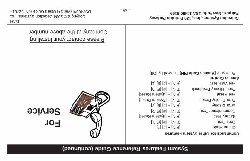
Commands for Other System Features
Chime Mode[PIN] + [#] [7]Zone Test[PIN] + [#] [8] [1]Battery Test[PIN] + [System Reset]Communicator Test[PIN] + [#] [8] [2]Error Display[PIN] + [#] [8] [7]Error Display Reset[PIN] + [System Reset]Fire Reset[PIN] + [System Reset]Event History Readback[PIN] + [#] [8] [9]Fire Walk Test[PIN] + [#] [9] [1]
Access ControlEnter your [Access Code PIN] followed by [Off].
System Features Reference Guide (continued)
Detection Systems, Inc., 130 Perinton ParkwayFairport, New York, USA 14450-9199
12/04Copyright © 2004 Detection Systems, Inc.
DS7400Xi (Ver. 3+) User’s Guide P/N: 32781F
Please contact your InstallingCompany at the above numberr
ForService
- 48 -