DRIVING RESISTANCE FACTOR CALCULATING …s2is.org/Issues/v5/n4/papers/paper14.pdf · The factor can...
14
DRIVING RESISTANCE FACTOR CALCULATING METHOD FOR PARALLEL-SERIAL HEV Hailong Guo 1,2 *, Lifu Li 1,3 1. College of Mechanical and Automotive Engineering South China University of Technology Guangzhou 510640, China 2. Guangdong Communication Polytechnic Guangzhou 510650, China 3. State Key Laboratory of Mechanical Transmission, Chongqing University Chongqing 400030, China Emails: [email protected] Submitted: Aug.18, 2012 Accepted: Oct.24, 2012 Published: Dec.1, 2012 Abstract- HEV’s energy control strategy cannot be regulated perfectly according to the variable working condition, because the driving resistance is difficult to measure and calculate during the driving process. By taking parallel-serial HEV which power coupling mechanism is planet-gear as research object, analyzed planet-gear power coupling mechanism’s dynamics characteristic and efficiency characteristic, put forward driving resistance factor’s concept and measure-calculating methods. The factor can be used to evaluate HEV’s driving resistance under different load and road INTERNATIONAL JOURNAL ON SMART SENSING AND INTELLIGENT SYSTEMS, VOL. 5, NO. 4, DECEMBER 2012 973
Transcript of DRIVING RESISTANCE FACTOR CALCULATING …s2is.org/Issues/v5/n4/papers/paper14.pdf · The factor can...
DRIVING RESISTANCE FACTOR CALCULATING METHOD
FOR PARALLEL-SERIAL HEV
Hailong Guo1,2
*, Lifu Li1,3
1. College of Mechanical and Automotive Engineering
South China University of Technology
Guangzhou 510640, China
2. Guangdong Communication Polytechnic
Guangzhou 510650, China
3. State Key Laboratory of Mechanical Transmission, Chongqing University
Chongqing 400030, China
Emails: [email protected]
Submitted: Aug.18, 2012 Accepted: Oct.24, 2012 Published: Dec.1, 2012
Abstract- HEV’s energy control strategy cannot be regulated perfectly according to the variable
working condition, because the driving resistance is difficult to measure and calculate during the
driving process. By taking parallel-serial HEV which power coupling mechanism is planet-gear as
research object, analyzed planet-gear power coupling mechanism’s dynamics characteristic and
efficiency characteristic, put forward driving resistance factor’s concept and measure-calculating
methods. The factor can be used to evaluate HEV’s driving resistance under different load and road
INTERNATIONAL JOURNAL ON SMART SENSING AND INTELLIGENT SYSTEMS, VOL. 5, NO. 4, DECEMBER 2012
973
gradient condition. The experiment results show that the maximum relative error of driving resistance
factor’s average value between theory calculating and experiment testing is 6.36%, which is found in
the large driving resistance working condition that the vehicle load is 305 kg, the road gradient is
5.2495°.
Index terms: Hybrid electric vehicle, planet gear, driving resistance factor, calculating method.
I. INTRODUCTION
When HEV drives in the different working condition under different load and road gradient,
driving resistance will be a great difference. If the driving resistance gets large, Power train must
increase the power out-put to meet HEV’s required dynamic characteristic, which will inevitably
lead to the increase of HEV energy consumption. So HEV’s energy control strategy should be
able to change with driving resistance to make appropriate adjustments. And then, make HEV’s
fuel economy and dynamic characteristics into a better balance. Because HEV’s driving real-time
resistance is hard to measure and estimate during the driving process, the current energy control
strategies have not considered the real-time travel resistance’s effect on control strategy[1]-[9].
Therefore, put forward the concept of "driving resistance factor" and its measuring method. The
index means that in HEV’s actual driving course, the ratio of the difference between Real-time
traffic driving resistance and benchmarks road condition(Flat road, 60 kg load) driving resistance
and the sum between HEV servicing quality and benchmarks load quality (60 kg).So the index
can be used to comprehensive evaluation of HEV real-time travel resistance magnitude, and to
provide the basis for dynamic adjustment of HEV energy control strategy.
II. THE STRUCTURE AND PARAMETERS OF PARALLEL-SERIES HEV’S
POWER COUPLING MECHANISM
Put a typical parallel-series type hybrid electric vehicle as the research object, the power coupling
mechanism is planetary gear system, as shown in Fig 1. The generator M1 is connected to the sun
round of planetary gear system, the engine is connected to the planet carrier, and the motor M2 is
connected to the ring gear. The final power output component of the coupling mechanism is the
Hailong Guo and Lifu Li, Driving Resistance Factor Calculating Method for Parallel-Serial HEV
974
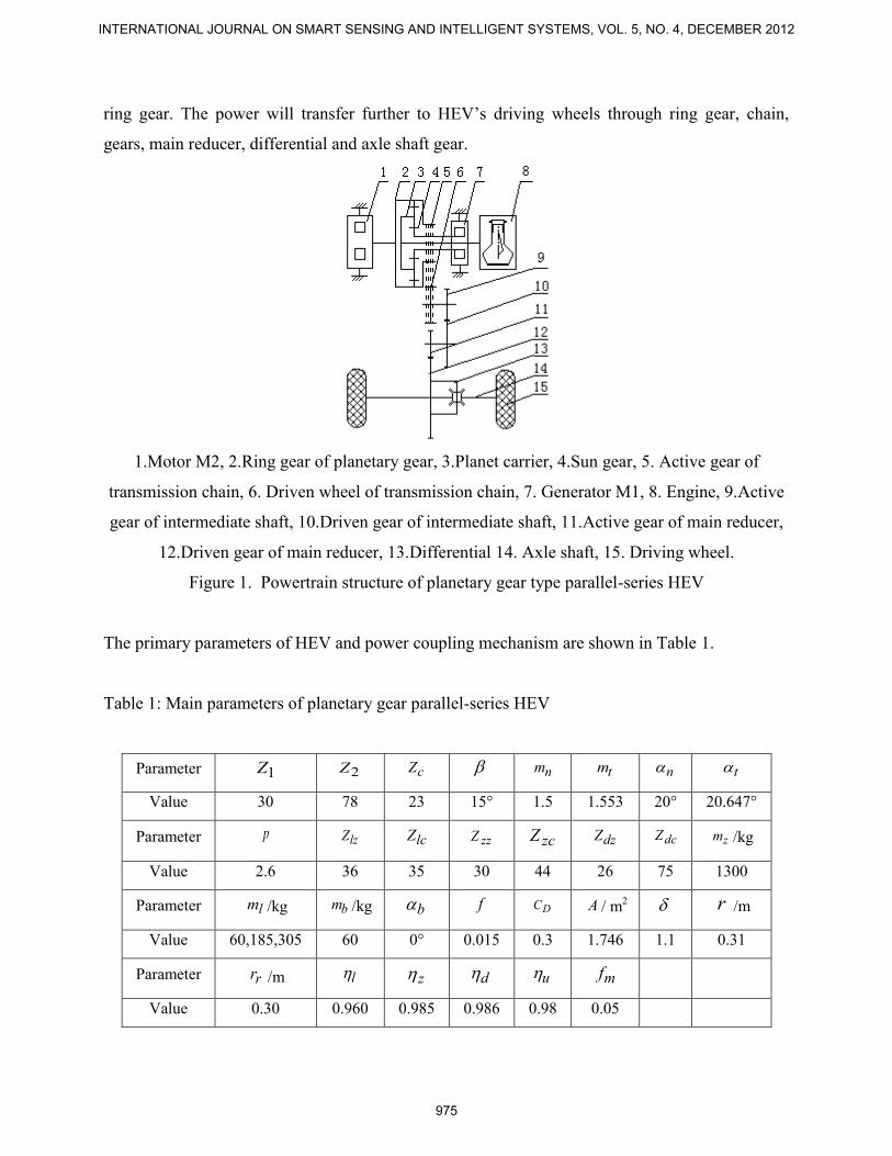
ring gear. The power will transfer further to HEV’s driving wheels through ring gear, chain,
gears, main reducer, differential and axle shaft gear.
1.Motor M2, 2.Ring gear of planetary gear, 3.Planet carrier, 4.Sun gear, 5. Active gear of
transmission chain, 6. Driven wheel of transmission chain, 7. Generator M1, 8. Engine, 9.Active
gear of intermediate shaft, 10.Driven gear of intermediate shaft, 11.Active gear of main reducer,
12.Driven gear of main reducer, 13.Differential 14. Axle shaft, 15. Driving wheel.
Figure 1. Powertrain structure of planetary gear type parallel-series HEV
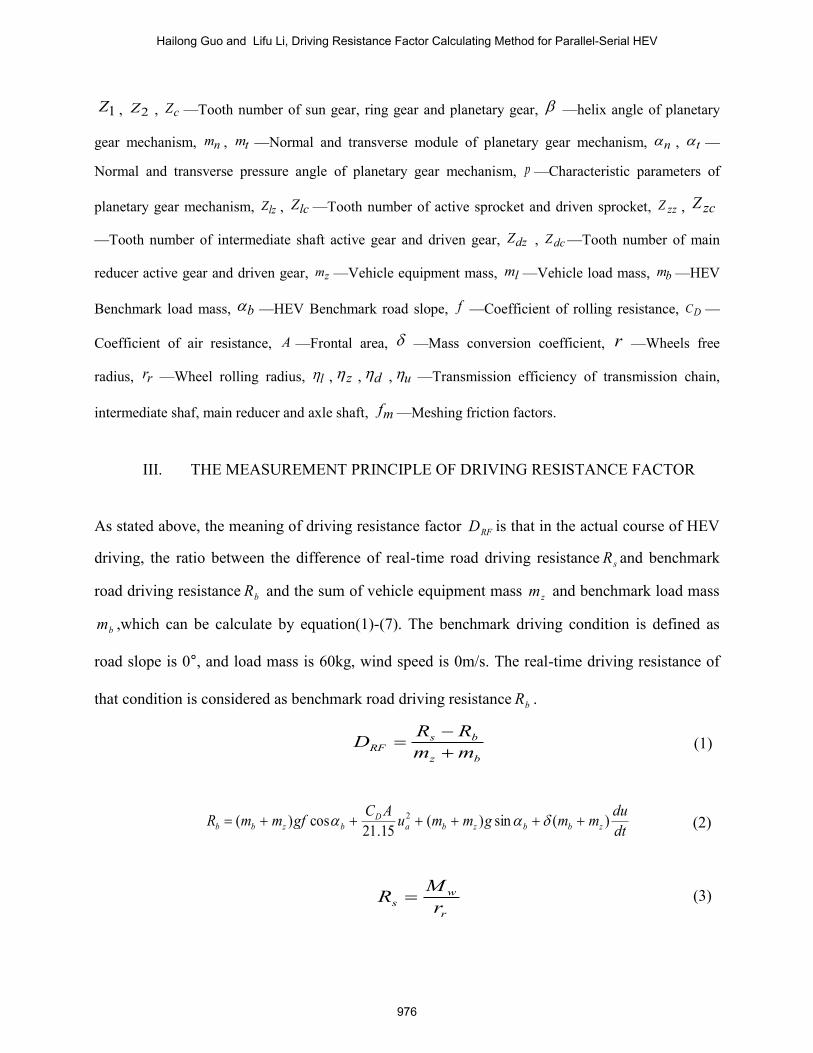
The primary parameters of HEV and power coupling mechanism are shown in Table 1.
Table 1: Main parameters of planetary gear parallel-series HEV
Parameter 1Z 2Z cZ nm tm n t
Value 30 78 23 15° 1.5 1.553 20° 20.647°
Parameter p lzZ lcZ zzZ zcZ dzZ dcZ zm /kg
Value 2.6 36 35 30 44 26 75 1300
Parameter lm /kg bm /kg b f DC A / m2 r /m
Value 60,185,305 60 0° 0.015 0.3 1.746 1.1 0.31
Parameter rr /m l z d u mf
Value 0.30 0.960 0.985 0.986 0.98 0.05
INTERNATIONAL JOURNAL ON SMART SENSING AND INTELLIGENT SYSTEMS, VOL. 5, NO. 4, DECEMBER 2012
975
1Z , 2Z , cZ —Tooth number of sun gear, ring gear and planetary gear, —helix angle of planetary
gear mechanism, nm , tm —Normal and transverse module of planetary gear mechanism, n , t —
Normal and transverse pressure angle of planetary gear mechanism, p —Characteristic parameters of
planetary gear mechanism, lzZ , lcZ —Tooth number of active sprocket and driven sprocket, zzZ , zcZ
—Tooth number of intermediate shaft active gear and driven gear, dzZ , dcZ —Tooth number of main
reducer active gear and driven gear, zm —Vehicle equipment mass,
lm —Vehicle load mass, bm —HEV
Benchmark load mass, b —HEV Benchmark road slope,
f —Coefficient of rolling resistance,
DC —
Coefficient of air resistance, A —Frontal area, —Mass conversion coefficient, r —Wheels free
radius, rr —Wheel rolling radius,
l , z , d , u —Transmission efficiency of transmission chain,
intermediate shaf, main reducer and axle shaft, mf —Meshing friction factors.
III. THE MEASUREMENT PRINCIPLE OF DRIVING RESISTANCE FACTOR
As stated above, the meaning of driving resistance factor RFD is that in the actual course of HEV
driving, the ratio between the difference of real-time road driving resistance sR and benchmark
road driving resistance bR and the sum of vehicle equipment mass zm and benchmark load mass
bm ,which can be calculate by equation(1)-(7). The benchmark driving condition is defined as
road slope is 0°, and load mass is 60kg, wind speed is 0m/s. The real-time driving resistance of
that condition is considered as benchmark road driving resistance bR .
bz
bsRF mm
RRD
(1)
dt
dummgmmu
ACgfmmR zbbzba
Dbzbb )(sin)(
15.21cos)( 2
(2)
r
ws r
MR (3)
Hailong Guo and Lifu Li, Driving Resistance Factor Calculating Method for Parallel-Serial HEV
976
00 iTM rw (4)
lzzzdz
lczcdc
ZZZ
ZZZi
0
(5)
udzl 0 (6)
mr TTT 2 (7)
In the equation(2)-(7), au is vehicle speed( hkm / ), u is vehicle speed( sm / )(Other driving
equation parameters refer to the literature12), wM is the wheel drive torque( mN ), rT is driving
resistance torque of the ring gear( mN ), 0i is transmission ratio from transmission chain to the
wheels, 0 is transmission efficiency from transmission chain to the wheels, 2T is the torque act
on the ring gear by engine and generator M1( mN ), mT is the torque act on the ring gear by
motor M2(the output torque of motor M2)( mN ).
In order to calculation 2T of equation (7), it is needed to carry out kinematics and dynamics
analysis on power coupling mechanism.
IV. KINEMATICS AND DYNAMICS ANALYSIS OF PLANET-GEAR POWER COUPLING
MECHANISM
a. Kinematics analysis of the power coupling mechanism
According to the theory of mechanics , from the planet-gear power coupling mechanism as
shown in fig 1, the transmission ratio of the planet-gear can be calculate by equation(8) and (9):
pZ
Z
ww
wwi
e
ee
1
2
2
112
, (8)
pii e
e 11 12
2
1, (9)
INTERNATIONAL JOURNAL ON SMART SENSING AND INTELLIGENT SYSTEMS, VOL. 5, NO. 4, DECEMBER 2012
977
In the equation, corner mark 1 represent the sun gear(also mean the generator M1) , 2 represent
the ring gear , e represent the planet carrier(also mean the engine) , the tooth number ratio
between the ring gear and the sun gear is defined as a characteristic parameter p of the planet-
gear mechanism , ei12 is the ratio between the relative angular velocity between sun gear and
planet carrier and the relative angular velocity between ring gear and planet carrier , 2
1ei is
analogy , w is rotational speed ( rpm ).
From the theory of machines, speeds between sun gear, ring gear and planet carrier in planet gear
mechanism has the following relationship[10]:
ee
e wiwiw 2
12121 (10)
Namely:
0)1(21 ewppww (11)
It is clear that , when the characteristic parameter of the planet-gear mechanism p is determined
, this mechanism has 2 degree of freedom, that means ew can be figured out through 1w and 2w .
From this HEV power coupling mechanism , the speed of sun gear 1w is equal to generator M1 ,
the speed of ring gear 2w is equal to motor M2 , the speed of planet carrier ew is equal to engine.
From the speed relations of planet-gear mechanism, the dynamics analysis of the power coupling
mechanism can be carried out.
b. Dynamics analysis of the power coupling mechanism
(1) Dynamics analysis of planet-gear mechanism
From the mechanical transmission power balance principle, the input and output power relation
of planet-gear mechanism can be acquired[11]:
0 BA PP
(12)
In the equation: AP is the input power (kW) of the driving part, BP is the output power (kW) of the
driven part, is mechanical transmission efficiency.
During the operation of the planet-gear mechanism, anyone of the three component is possible to
be driving part or driven part. With different driving-driven relation and different speed relation ,
planet-gear’s power balance equation and efficiency equation are different. Here we carry
Hailong Guo and Lifu Li, Driving Resistance Factor Calculating Method for Parallel-Serial HEV
978
through the derivation in the following condition: 021 www e , engine is driving component
, generator M1 and ring gear is driven component.
From the power balance equation (12), we can get:
02211)12( wTwTwT eee
(13)
In order to work out the torque relation between sun gear and planet carrier, we take item 2 as a
transform item, so we have the following equation:
02
11
2
)12( wTwT eee (14)
Further derivation:
1
1)12(
2
1)12(2
2
)12(1
1
p
iw
w
T
Teee
ee
e
(15)
In the equation: 1T is torque in the sun gear, also mean generator torque( mN. ), eT is torque in
the planet carrier, also mean engine torque( mN. ), )12(e is efficiency of the planetary gear system
when engine is driving part and generator and ring gear is driven part, 2
1w is angular velocity(
rpm ) of sun gear relative to ring gear, 2
ew ,1
2w and 1
ew has the similar meaning.
In order to work out the torque relation between engine and ring gear, we take item 1 as a
transform item, so we have the following equation:
01
22
1
)12( wTwT eee (16)
Further derivation:
1)12(
1
2)12(1
2
1
)12(2
p
pi
w
w
T
Teee
ee
e
(17)
From equation (17) , we can figure out the torque 2T that engine and generator act on ring gear.
The efficiency of the planetary gear mechanism can be figured out through the following
equation [10]
:
98.0)1(
1 21
21
1)12(
e
e
ee
ee
wwp
ww
(18)
In the equation: e
12 is transmission loss coefficient of planet-gear.
(2) Calculation of transmission loss coefficient of planet-gear
INTERNATIONAL JOURNAL ON SMART SENSING AND INTELLIGENT SYSTEMS, VOL. 5, NO. 4, DECEMBER 2012
979
The transmission loss coefficient of planet-gear in equation (18) can use equation(19) to figure
out:
e
n
e
m
e
m
e
n
e
m
ee 212112 (19)
In the equation: e
m is meshing loss coefficient , e
n is bearing loss coefficient , e
m1 is meshing
loss between sun gear and planet carrier in the transform mechanism , e
m2 is meshing loss
between ring gear and planet gear in the transform mechanism.
Because the loss cause by bearing friction has already been calculated in the calculation of the
overall efficiency of planet-gear, so we just consider the meshing loss coefficient, so:
))(11
(21
22
1
11
c
c
cm
e
m ZZf
(20)
))(11
(22
2
2
2
22
c
c
cm
e
m ZZf
(21)
In the equation: mf is meshing friction factors, 1 , 2 , c is the section transverse contact
ratio calculated by the length of the addendum line of action of sun gear 1 ,ring gear 2 and planet
gear c,
)'tan(tan2 1
11
t
Z (22)
)'tantan(2 2
22
t
Z (23)
)'tan(tan2
tcc
c
Z (24)
In the equation: 1t , 2t , tc is the addendum circle pressure angle of sun gear 1 ,ring gear 2
and planet gear c, ' is meshing angle(deg) of gears,
1
11 arccos
a
bat d
d ,
2
22 arccos
a
bat d
d , and
ac
bcatc d
darccos (25a, b, c)
In the equation: 1ad , 1bd is addendum circle diameter and base circle diameter(mm) of sun gear 1,
2ad , 2bd is addendum circle diameter and base circle diameter(mm) of ring gear 2, acd bcd is
addendum circle diameter and base circle diameter(mm) of planet gear c.
(3) Calculation of transmission loss coefficient of planet-gear
In order to figure out the gear parameters in equation (25a, b, c), we need to calculate the
component size of planet-gear. From the correct meshing condition of helical planet-gear
Hailong Guo and Lifu Li, Driving Resistance Factor Calculating Method for Parallel-Serial HEV
980
mechanism, the normal module and normal pressure angle of sun gear, ring gear and planet gear
are equal. As well as the helical angle of internal gear pair is equal and the helical angle of
external gear pair is opposite number. Thus the geometry size parameters of each component of
planet-gear are as follow, where d presents pitch diameter, ah represents height of addendum,
ad represents addendum circle diameter, bd represents base circle diameter:
For sun gear 1:
587.4611 Zmd t (26)
5.1 na mh
(27)
587.49211 aa hdd
(28)
595.43cos11 tb dd
(29)
For ring gear 2:
134.12122 Zmd t (30)
5.1 na mh
(31)
134.118222 aa hdd
(32)
357.113cos22 tb dd
(33)
For planet gear c:
719.35 ctc Zmd (34)
5.1 na mh (35)
719.382 acac hdd (36)
426.33cos tcbc dd (37)
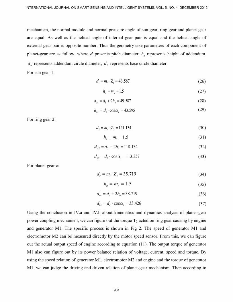
Using the conclusion in IV.a and IV.b about kinematics and dynamics analysis of planet-gear
power coupling mechanism, we can figure out the torque T2 acted on ring gear causing by engine
and generator M1. The specific process is shown in Fig 2. The speed of generator M1 and
electromotor M2 can be measured directly by the motor speed sensor. From this, we can figure
out the actual output speed of engine according to equation (11). The output torque of generator
M1 also can figure out by its power balance relation of voltage, current, speed and torque. By
using the speed relation of generator M1, electromotor M2 and engine and the torque of generator
M1, we can judge the driving and driven relation of planet-gear mechanism. Then according to
INTERNATIONAL JOURNAL ON SMART SENSING AND INTELLIGENT SYSTEMS, VOL. 5, NO. 4, DECEMBER 2012
981
equation (15) to figure out the actual output torque of engine, and then according to equation(17)
to figure out torque T2.
Figure 2. The computational procedure of the torque act on ring gear causing by engine and
generator M1
Above we analyzed the planet-gear mechanism in the condition of 021 www e , and engine
is driving component, generator M1 and ring gear is driven component. The other condition is
analogy.
V. EXPERIMENT TESTING AND RESULTS ANALYSIS
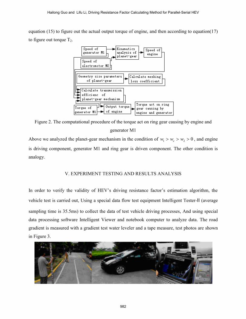
In order to verify the validity of HEV’s driving resistance factor’s estimation algorithm, the
vehicle test is carried out, Using a special data flow test equipment Intelligent Tester-Ⅱ (average
sampling time is 35.5ms) to collect the data of test vehicle driving processes, And using special
data processing software Intelligent Viewer and notebook computer to analyze data. The road
gradient is measured with a gradient test water leveler and a tape measure, test photos are shown
in Figure 3.
Hailong Guo and Lifu Li, Driving Resistance Factor Calculating Method for Parallel-Serial HEV
982
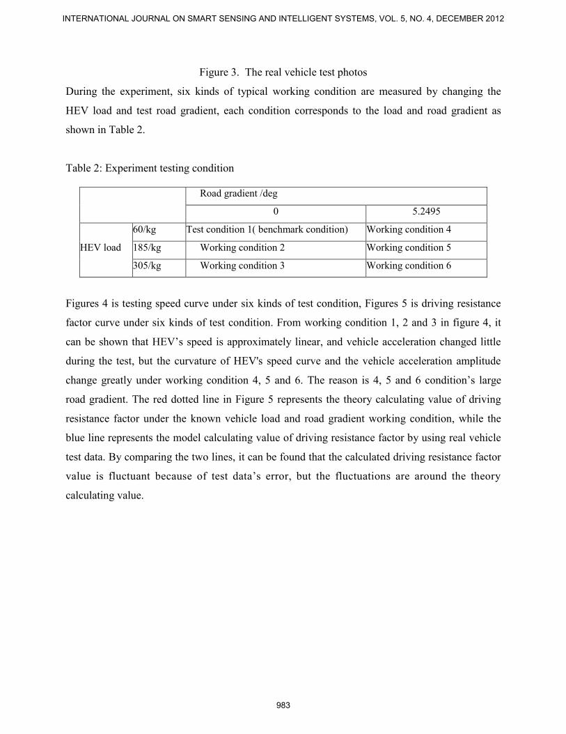
Figure 3. The real vehicle test photos
During the experiment, six kinds of typical working condition are measured by changing the
HEV load and test road gradient, each condition corresponds to the load and road gradient as
shown in Table 2.
Table 2: Experiment testing condition
Figures 4 is testing speed curve under six kinds of test condition, Figures 5 is driving resistance
factor curve under six kinds of test condition. From working condition 1, 2 and 3 in figure 4, it
can be shown that HEV’s speed is approximately linear, and vehicle acceleration changed little
during the test, but the curvature of HEV's speed curve and the vehicle acceleration amplitude
change greatly under working condition 4, 5 and 6. The reason is 4, 5 and 6 condition’s large
road gradient. The red dotted line in Figure 5 represents the theory calculating value of driving
resistance factor under the known vehicle load and road gradient working condition, while the
blue line represents the model calculating value of driving resistance factor by using real vehicle
test data. By comparing the two lines, it can be found that the calculated driving resistance factor
value is fluctuant because of test data’s error, but the fluctuations are around the theory
calculating value.
Road gradient /deg
0 5.2495
HEV load
60/kg Test condition 1( benchmark condition) Working condition 4
185/kg Working condition 2 Working condition 5
305/kg Working condition 3 Working condition 6
INTERNATIONAL JOURNAL ON SMART SENSING AND INTELLIGENT SYSTEMS, VOL. 5, NO. 4, DECEMBER 2012
983
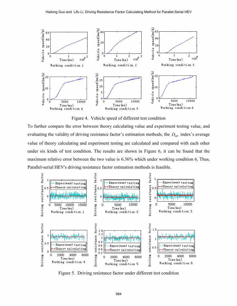
Figure 4. Vehicle speed of different test condition
To further compare the error between theory calculating value and experiment testing value, and
evaluating the validity of driving resistance factor’s estimation methods, the RFD index’s average
value of theory calculating and experiment testing are calculated and compared with each other
under six kinds of test condition. The results are shown in Figure 6, it can be found that the
maximum relative error between the two value is 6.36% which under working condition 6, Thus,
Parallel-serial HEV's driving resistance factor estimation methods is feasible.
Figure 5. Driving resistance factor under different test condition
Hailong Guo and Lifu Li, Driving Resistance Factor Calculating Method for Parallel-Serial HEV
984
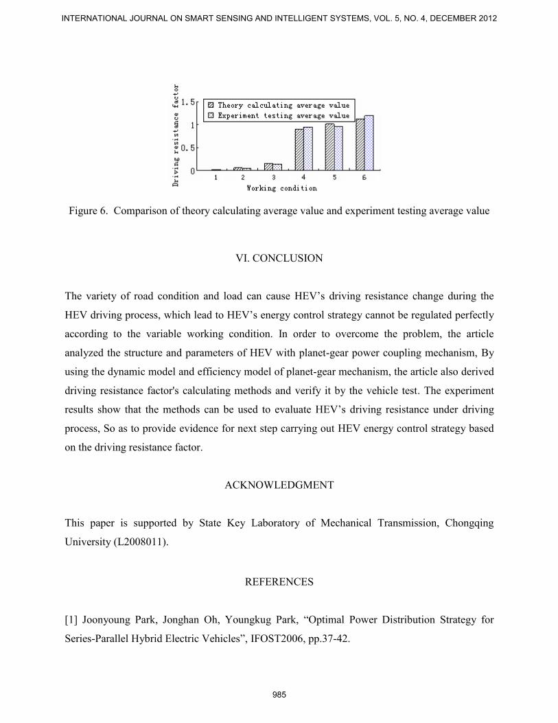
Figure 6. Comparison of theory calculating average value and experiment testing average value
VI. CONCLUSION
The variety of road condition and load can cause HEV’s driving resistance change during the
HEV driving process, which lead to HEV’s energy control strategy cannot be regulated perfectly
according to the variable working condition. In order to overcome the problem, the article
analyzed the structure and parameters of HEV with planet-gear power coupling mechanism, By
using the dynamic model and efficiency model of planet-gear mechanism, the article also derived
driving resistance factor's calculating methods and verify it by the vehicle test. The experiment
results show that the methods can be used to evaluate HEV’s driving resistance under driving
process, So as to provide evidence for next step carrying out HEV energy control strategy based
on the driving resistance factor.
ACKNOWLEDGMENT
This paper is supported by State Key Laboratory of Mechanical Transmission, Chongqing
University (L2008011).
REFERENCES
[1] Joonyoung Park, Jonghan Oh, Youngkug Park, “Optimal Power Distribution Strategy for
Series-Parallel Hybrid Electric Vehicles”, IFOST2006, pp.37-42.
INTERNATIONAL JOURNAL ON SMART SENSING AND INTELLIGENT SYSTEMS, VOL. 5, NO. 4, DECEMBER 2012
985
[2] Sungtae Cho, Kukhyun Ahn, Jang Moo Lee, “Efficiency of the planetary gear hybrid
powertrain”, Proc. IMechE, Vol.220, No.6, June 2006, pp.1445-1454.
[3] Chen Shanglou, Wang Lifang, Liao Chenglin, „Realization of an energy management strategy
for a series-parallel hybrid electric vehicle”, IEEE Vehicle Power and Propulsion Conference
2008, pp.66-71.
[4] Zuo Yihe, Xiang Changle, Yan qingdong, “Control Strategy of Parallel-serial Hybrid
Electrical Vehicle Based on the Power Track Method”, Transactions of the Chinese Society for
Agricultural Machinery, Vol.40, No.12, June 2009 , pp. 23-29.
[5] Cheng Y, Chen K, Chan C C, “Global Modeling and Control Strategy Simulation using
Electrical Variable Transmission in Hybrid Electric Vehicles”, IEEE Vehicular Technology
Magazine, Vol.4, No.2, June 2009, pp.73-79.
[6] Shu Hong, Liu Wenjie, Yan Jinmin, “Optimization of Energy Management Strategy for a
Parallel-series HEV”, Transactions of the Chinese Society for Agricultural Machinery, Vol.40,
No.3, June 2009 , pp.31-55.
[7] W. Jatmiko, A. Azurat and Herry, “Self-Organizing Urban Traffic Control Architecture With
Swarm-Self Organizing Map In Jakarta: Signal Control System And Simulator”, International
Journal on Smart Sensing and Intelligent Systems, Vol.3, No.3, 2010, pp. 443-465.
[8] A. A. Aldair and W. J. Wang, “Design An Intelligent Controller For Full Vehicle Nonlinear
Active Suspension Systems”, International Journal On Smart Sensing and Intelligent Systems
Vol.4, No.2, 2011, pp. 224-243.
[9] Niassar A H , Moghbelli H , Vahedi A , “Design methodology of drive train for a series-
parallel hybrid electric vehicle (SP-HEV) and its power flow control strategy”, IEEE trans, 2005,
pp.1549-1554.
[10] Rao Chenggang, “Designing on Planetary Gear System”, Beijing: Chemical Industry
Press,2003.
[11] Sun Heng, Chen Zuomo, Ge Wenjie, “Theory of Mechanics”, Beijing: Higher Education
Press, 2006.
[12] Yu Zhisheng, “Theory of Automobile”, Beijing: Machinery Industry Press, 2006.
Hailong Guo and Lifu Li, Driving Resistance Factor Calculating Method for Parallel-Serial HEV
986