Drift Limita
9
Drift minimization of tall building frames Md Kamruzzaman*, Bangladesh Institute of Technology, Bangladesh Md M Sazzad, Bangladesh Institute of Technology, Bangladesh T Ahmed, Bangladesh Institute of Technology, Bangladesh 27th Conference on OUR WORLD IN CONCRETE & STRUCTURES: 29 - 30 August 2002, Singapore Article Online Id: 100027045 The online version of this article can be found at: http://cipremier.com/100027045 This article is brought to you with the support of Singapore Concrete Institute www.scinst.org.sg All Rights reserved for CI‐Premier PTE LTD You are not Allowed to re‐distribute or re‐sale the article in any format without written approval of CI‐Premier PTE LTD Visit Our Website for more information www.cipremier.com
-
Upload
kalidindivenkataraju -
Category
Documents
-
view
12 -
download
0
Transcript of Drift Limita
Drift minimization of tall building frames
Md Kamruzzaman*, Bangladesh Institute of Technology, Bangladesh Md M Sazzad, Bangladesh Institute of Technology, Bangladesh
T Ahmed, Bangladesh Institute of Technology, Bangladesh
27th Conference on OUR WORLD IN CONCRETE & STRUCTURES: 29 - 30 August 2002,
Singapore
Article Online Id: 100027045
The online version of this article can be found at:
http://cipremier.com/100027045
This article is brought to you with the support of
Singapore Concrete Institute
www.scinst.org.sg
All Rights reserved for CI‐Premier PTE LTD
You are not Allowed to re‐distribute or re‐sale the article in any format without written approval of
CI‐Premier PTE LTD
Visit Our Website for more information
www.cipremier.com
27'"' Conference on OUR WORLD IN CONCRETE & STRUCTURES: 29 - 30 August 2002, Singapore
Drift minimization of tall building frames
Md Kamruzzaman*, Bangladesh Institute of Technology, Bangladesh Md M Sazzad, Bangladesh Institute of Technology, Bangladesh
T Ahmed, Bangladesh Institute of Technology, Bangladesh
Abstract
Drift is a dominant feature in tall building design. Lateral loads (i.e. wind or earthquake loads) are mainly responsible for drift which very often dictates the selection of structural systems for high rise buildings. To bring the maximum drift down to allowable limits cross sectional dimensions of beams and columns have to be increased in many cases. For buildings having small number of storey, the design is rarely affected by lateral loads. But when the height of the building increases, the increase in size of structural members and the possible rearrangements of the structure to account for lateral loads incurs a cost premium. Thus if it is possible to introduce certain techniques to utilize the full capacities of the structural elements, the savings in materials and cost can be achieved. This paper presents the results of an investigation into characterization of tall building frames under lateral loads, drift and its minimization. The 'Displacement Participation Factor (DPF)' approach is used to identify the members, which contributes significantly to drift. Besides a computer program has been developed to compute the deflection, strain energy and DPF of the members. Through the investigation DPF of beams and columns that contribute to maximum lateral sway are identified. Then it is shown that considerable reduction in drift can be achieved by increasing the moment of inertia (stiffness) of 2nd to 5th floor beams up to 30 storey frames.
Keywords: Tall building, drift, DPF, top deflection, drift index, lateral loads, point loading, UDL, triangular loading, stiffness, strain energy, bay width.
1. Introduction
Tallness is a relative matter and tall buildings can not be defined in a specific term related just to height or to the number of floors. The tallness of a building is a matter of a person's or community's circumstance and their consequent perception, therefore, a measurable definition of a tall building can not be universally applied. The Council of Tall Buildings and Urban Habitat considers building having 9 or more stories as high-rise structures. Therefore there is no consensus on what constitutes a tall building at what magic height, number of stories or proportion a building can be called tall. Perhaps the dividing line should be drawn where the design of the tall structures moves from the field of static into the field of structural dynamics. From the structural engineer's point of view, however, a tall building may be defined as one that, because of its height, is affected by lateral forces due to wind or earthquake actions to an extent that they play an important role in the structural design.
351
In tall building design drift is a dominant feature. Drift may be defined as the displacement of one level relative to the level above or below due to the design lateral forces. Lateral loads (i.e. wind and earthquake) are responsible for the drift, which is a headache to structural engineers. This drift very often dictates the selection of structural system. To bring the drift down to allowable limits crosssectional dimension of beams and columns have to be increased. So the structural characterization and drift minimization of tall building frames under lateral load is highly important.
Sound engineering judgement is required when deciding on the drift index to be imposed. Drift index is the ratio of the maximum deflection at the top of building to the total height. Design drift index limits that have been used in different countries range from 0.001 to 0.005. To put this in perspective, a maximum horizontal top deflection of between 0.1 and 0.5m (6 to 20 inch) would be allowed in a 33 storey[5]. Generally, lower values should be used for hotels or apartment buildings than for office buildings, since noise and movement tend to be more disturbing in the former. Consideration may be given to whether the stiffness effects of any internal partitions, infills, or claddings are included in the deflection calculations.
2. Analysis approach
As the subject matter concerns with the behavior of the tall building frames under lateral loads, so the term drift obviously come to the discussion. For the analysis of tall planar frames, deformation arises from flexural, axial and shear distortion occurring within the beams, columns and beam-column joints can be computed by displacement participation factor approach. A displacement participation factor is a numeric value, which represents that member's contribution to the displacement occurring at a specific point and in a specific direction. For example, if it is known that the lateral displacement at the roof of a 40-storey tube is 500 mm, and the displacement participation factor for a column at the base of the structure has been calculated to be 2.5 mm, that member is responsible for 2.5/500 or 0.5% of the total drift. The sum of the displacement participation factor for all the members of the structure is equal to the displacement at the specified location.
The principle of virtual work constitutes the most versatile method available for evaluating elastic deflections of structures. Not only it is possible to determine the deflections resulting from loads of any type, causing any kind of strains in a structure, but it is also possible to compute deflections resulting from temperature changes, errors in fabrication, or shrinkage of the structural material.
According to the principle of the virtual work [7],
External work = Internal work. i.e. PxM2=U Ll=(2/P) xU ..................... (1)
For whole structure, m
~ = LUx2/P ............ (2) i=1
Where, Ll= Displacement P= Applied load U= Strain energy m= No. of member
It can be easily seen that each of the products in the summation on the equation (2) represents the contribution of that member to the overall displacement.
Hence equation (2) may be written as, m
~ = L DPFj .............................. (3)
i=1
352
Where, DPF j =Displacement participation factor
The analysis of rigid frame buildings is accomplished most efficiently by using stiffness analysis programs. A computer program in FORTRAN VISUAL WORKBEI\JCH is developed to compute the deflection, strain energy and displacement participation factor (DPF) of the members.
3. Analysis
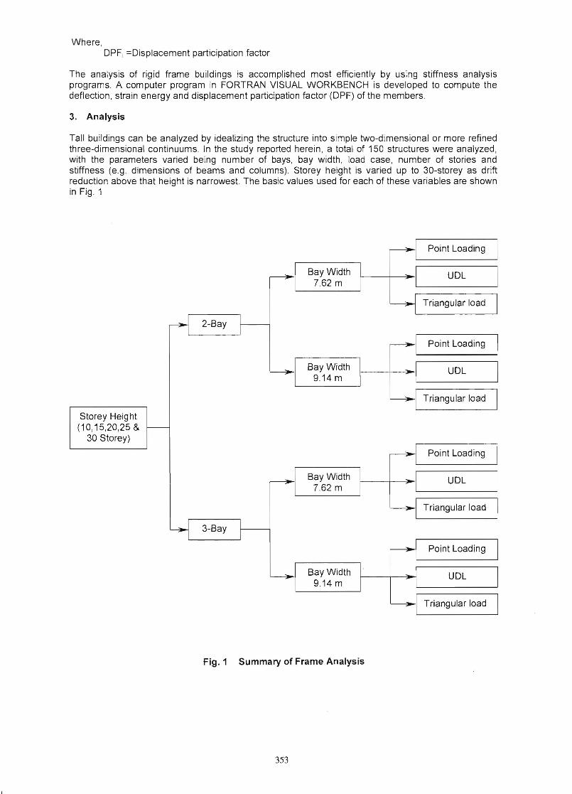
Tali buildings can be analyzed by idealizing the structure into simple two-dimensional or more refined three-dimensional continuums. In the study reported herein, a total of 150 structures were analyzed, with the parameters varied being number of bays, bay width, load case, number of stories and stiffness (e.g. dimensions of beams and columns). Storey height is varied up to 30-storey as drift reduction above that height is narrowest. The basic values used for each of these variables are shown in Fig. 1
Point Loading
Bay Width I UDL 7.62 m
~ Triangular load
2-Bay
Point Loading
~ Bay Width
9.14 m UDL
Triangular load
Storey Heig ht (10,15,20,25 &
30 Storey)
Point Loading
Bay Width UDL 7.62 m
~I Triangular load
3-Bay
Point Loading
Bay Width UDL 9.14 m
Triangular load
Fig. 1 Summary of Frame Analysis
353
Lateral load cases like UDL fer wind load , triangu lar load for earthquake load and point loads subjected from shear wall are implied on different frames . Through the investigation carried on by computer program , the DPF(%) values of different stories are ca lculated .
A typical 15-storey frame is shown in Fig. 2
(74) (75)
A=0.46 m2(43) (44) (45)
...-
(60) (61 ) (22) (23) (24)
11\
(46) (47)
(1 ) (2) (3)
IE---- [email protected]=15.24m ----71
I
1=0.017 m4
A=0.56 m 2
1=0.026 m4
1 A=1 .86 m 2
=0.0256 m4
[Numbers in the parenthesis indicate number of the member]
Fig. 2 15-Storey Frame
The 1st, 2nd , and 3rd maximum DPF(%) contribution of different floor beams along with their values are tabulated and given below.
Table 1. Point Loading
No of Storey
DPF(%) contribution with position of floor beam 1 st position 2nd position 3rd position
Floor position
DPF (%) Floor
position DPF (%)
Floor position
DPF (%)
10 51r 3.56 61r 3.55 4u 3.54 15 51r 2.04 61n 2.04 4'" 2.00 20 51n 1.31 61r 1.30 4tn 1.29 25 51r 0.88 6" 0.087 41
1' 0.87 30 51n 0.61 6tn 0.06 4\0 0.59
Table 2. UDL
No of Storey
DPF(%) contribution with position of floor beam 1 st position 2nd position 3rd position
Floor position
DPF(%) Floor
posit ion DPF (%)
Floor position
DPF (%)
10 2na 7.33 1s 6.58 3ru 5.95 15 2M 5.13 3
ra 4 .62 151 4.27 20 2na 3.74 3ra 3.51 4" 3.14 25 2M 2.80 3ra 2.70 4tn 2.48 30 2na 2.15 3ra 2.10 4" 1.97
354
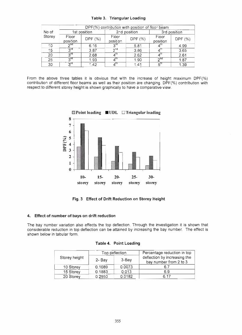
Table 3. Triangular Loading
No of Storey
DPF(%) contribution with position of floor beam 1 st position 2nd position 3rd position
Floor position DPF (%) Floor
position DPF(%) Floor position DPF (%)
10 2na 6.16 3ra 5.81 4'" 4.99 15 3ra 3.87 2na 3.86 4'" 3.65 20 3ra 2.68 410 2.62 410 2.61 25 3ra 1.93 4" 1.90 2na 1.87 30 3ra 1.42 4" 1.41 51n 1.39
From the above three tables it is obvious that with the increase of height maximum DPF(%) contribution of different floor beams as well as their position are changing. DPF(%) contribution with respect to different storey height is shown graphically to have a comparative view.
DPoint loading .UDL DTriangular loading
8
7
6 r
~5Q
~4 - r~ ~ 3
I
2 r -1
o ' I I , I l~ l~ 2~ 2~ 3~
storey storey storey storey storey
Fig. 3 Effect of Drift Reduction on Storey Height
4. Effect of number of bays on drift reduction
The bay number variation also effects the top deflection . Through the investigation it is shown that considerable reduction in top deflection can be attained by increasing the bay number. The effect is shown below in tabular form.
Table 4. Point Loading
Storey height Top deflection Percentage reduction in top
deflection by increasing the bay number from 2 to 3 2- Bay 3-Bay
10 Storey 0.1089 0.0073 6.7 15 Storey 0.1883 0.013 6.9 20 Storey 0.2950 0.0182 6.17
355
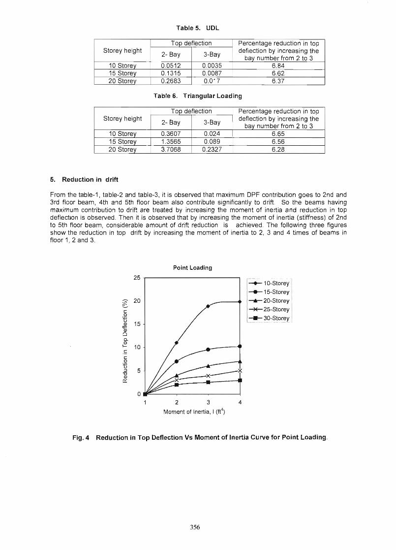
Table 5. UDL
Storey height Top deflection Percentage reduction in top
deflection by increasing the bay number from 2 to 3
2- Bay 3-Bay
10 Storey 0.0512 0.0035 6.84 15 Storey 0.1315 0.0087 6.62 20 Storey 0.2683 0.017 6.37
Table 6. Triangular Loading
Storey height Top deflection Percentage reduction in top
deflection by increasing the bay number from 2 to 32- Bay 3-Bay
10 Storey 0.3607 0.024 6.65 15 Storey 1.3565 0.089 6.56 20 Storey 3.7068 0.2327 6.28
5. Reduction in drift
From the table-1, table-2 and table-3, it is observed that maximum DPF contribution goes to 2nd and 3rd floor beam, 4th and 5th floor beam also contribute significantly to drift. So the beams having maximum contribution to drift are treated by increasing the moment of inertia and reduction in top deflection is observed . Then it is observed that by increasing the moment of inertia (stiffness) of 2nd to 5th floor beam, considerable amount of drift reduction is achieved . The following three figures show the reduction in top drift by increasing the moment of inertia to 2, 3 and 4 times of beams in floor 1, 2 and 3.
Point Loading
25
20~ !;!.... £: 0
TI Q) 15
I;:: Q)
0 a. 0 I 10 £:
£: 0
~ :J 5
"C Q)
0::
0
4
~10-Storey
-e- 15-Storey
--.- 20-Storey
~25-Storey
__ 30-Storey
2 3
Moment of Inertia, I (ft4)
Fig.4 Reduction in Top Deflection Vs Moment of Inertia Curve for Point Loading.
356
UDL
30 ,------------------------,
-
1-+.- 10-Sto-rey I i-.- 15-Storey Ii1 25
c ---6- 20-Storey I o .~ 20 -x- 25-Storey I
1
~ l.~_3~-StorerJo g. 15 r-c c o 10 t3 :::l "0 Q)
n::: 5
o~------~-------,------~ 2 3 4
Moment of Inertia, I (ft4)
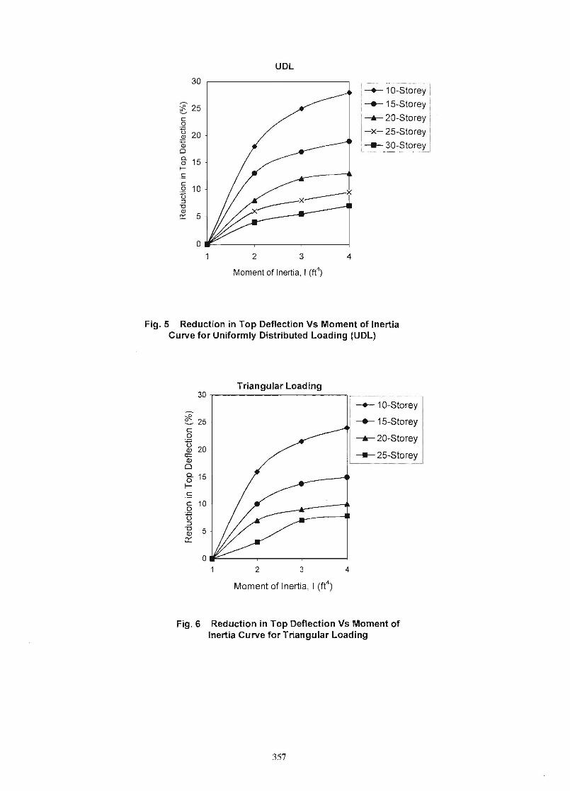
Fig. 5 Reduction in Top Deflection Vs Moment of Inertia Curve for Uniformly Distributed Loading (UDL)
Triangular Loading 30r---------------------~
I-~ 1O--Sto~~y-
~ 25 I -.- 15-Storey c o ---6- 20-StoreyU Q) 20
<+= -25-StoreyQ)
o g- 15 I-c c 10 o U =:l
-g 5cr::
o.r~----~------~----~
2 3 4
Moment of Inertia, I (ft4)
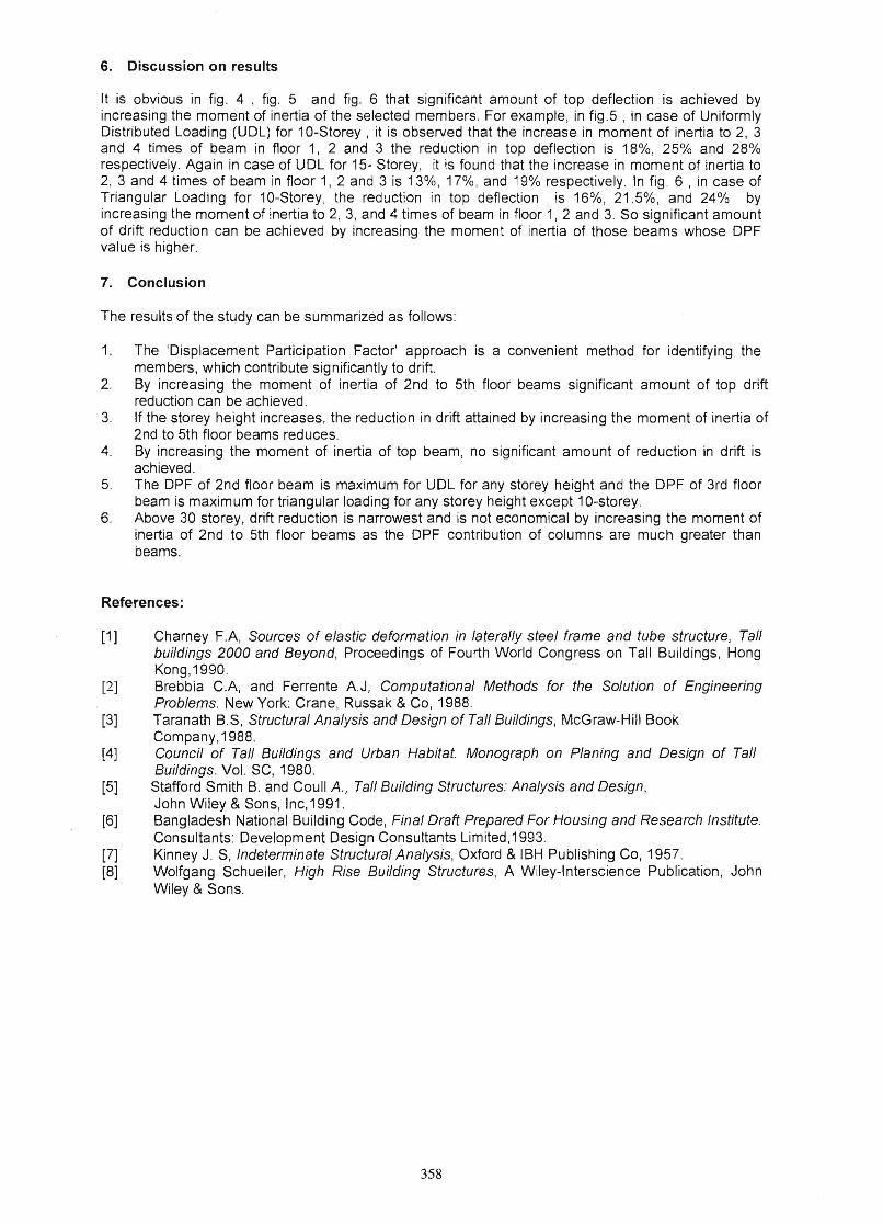
Fig.6 Reduction in Top Deflection Vs Moment of Inertia Curve for Triangular Loading
357
6. Discussion on results
It is obvious in fig . 4 , fig. 5 and fig. 6 that significant amount of top deflection is achieved by increasing the moment of inertia of the selected members. For example, in fig.5 , in case of Uniformly Distributed Loading (UDL) for 10-Storey , it is observed that the increase in moment of inertia to 2, 3 and 4 times of beam in floor 1, 2 and 3 the red uction in top deflection is 18%, 25% and 28% respectively. Again in case of UDL for 15- Storey, it is found that the increase in moment of inertia to 2, 3 and 4 times of beam in floor 1, 2 and 3 is 13%, 17%, and 19% respectively. In fig . 6 , in case of Triangular Loading for 10-Storey, the reduction in top deflection is 16%, 21.5%, and 24% by increasing the moment of inertia to 2, 3, and 4 times of beam in floor 1, 2 and 3. So significant amount of drift reduction can be achieved by increasing the moment of inertia of those beams whose DPF value is higher.
7. Conclusion
The results of the study can be summarized as follows :
1. The 'Displacement Participation Factor' approach is a convenient method for identifying the members, which contribute significantly to drift.
2. By increasing the moment of inertia of 2nd to 5th floor beams significant amount of top drift reduction can be achieved.
3. If the storey height increases, the reduction in drift attained by increasing the moment of inertia of 2nd to 5th floor beams reduces.
4. By increasing the moment of inertia of top beam, no significant amount of reduction in drift is achieved.
5. The DPF of 2nd floor beam is maximum for UDL for any storey height and the DPF of 3rd floor beam is maximum for triangular loading for any storey height except 10-storey.
6. Above 30 storey, drift reduction is narrowest and is not economical by increasing the moment of inertia of 2nd to 5th floor beams as the DPF contribution of columns are much greater than beams.
References:
[1] Charney F .A, Sources of elastic deformation in laterally steel frame and tube structure, Tall buildings 2000 and Beyond, Proceedings of Fourth World Congress on Tall Buildings, Hong Kong,1990 .
[2] Brebbia C.A, and Ferrente AJ, Computational Methods for the Solution of Engineering Problems. New York: Crane, Russak & Co, 1988.
[3] Taranath B.S, Structural Analysis and Design of Tall Buildings, McGraw-Hili Book Company,1988.
[4] Council of Tall Buildings and Urban Habitat. Monograph on Planing and Design of Tall Buildings. Vol. SC, 1980.
[5] Stafford Smith B. and Coull A., Tall Building Structures: Analysis and Design, John Wiley & Sons, Inc,1991.
[6] Bangladesh National Building Code, Final Draft Prepared For Housing and Research Institute. Consultants: Development Design Consultants Limited , 1993.
[7] Kinney J. S, Indeterminate Structural Analysis, Oxford & IBH Publishing Co, 1957. [8] Wolfgang Schueller, High Rise Building Structures, A Wiley-Interscience Publication, John
Wiley & Sons.
358