Drawing standards - beta.bathes.gov.uk
15
Drawing standards Planning application guidance - plans and drawings March 2017 (Adopted by North Somerset Council as local planning application requirement part 3) This guidance note is designed to provide information to applicants on the type and standard of plans and drawings that should be submitted in support of a planning application. It has been formally adopted by North Somerset Council as local planning application requirement part 3 and is used to decide if an application is valid. It was prepared by three of the West of England Planning Authorities to achieve a common standard.
Transcript of Drawing standards - beta.bathes.gov.uk
Drawing standards
Planning application guidance - plans and
drawings March 2017
(Adopted by North Somerset Council as local planning application requirement part 3)
This guidance note is designed to provide information to applicants on the type and standard of plans and drawings that should be submitted in support of a planning application. It has been formally adopted by North Somerset Council as local planning application requirement part 3 and is used to decide if an application is valid. It was prepared by three of the West of England Planning Authorities to achieve a common standard.
1
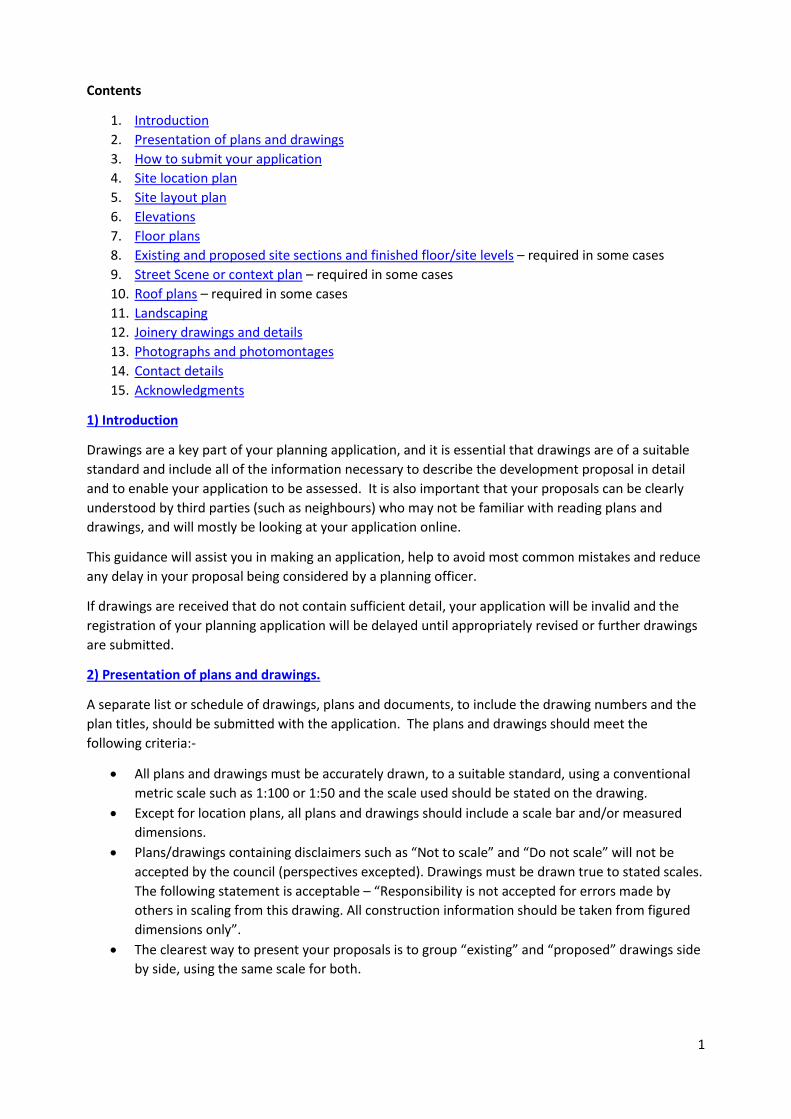
Contents
1. Introduction
2. Presentation of plans and drawings
3. How to submit your application
4. Site location plan
5. Site layout plan
6. Elevations
7. Floor plans
8. Existing and proposed site sections and finished floor/site levels – required in some cases
9. Street Scene or context plan – required in some cases
10. Roof plans – required in some cases
11. Landscaping
12. Joinery drawings and details
13. Photographs and photomontages
14. Contact details
15. Acknowledgments
1) Introduction
Drawings are a key part of your planning application, and it is essential that drawings are of a suitable
standard and include all of the information necessary to describe the development proposal in detail
and to enable your application to be assessed. It is also important that your proposals can be clearly
understood by third parties (such as neighbours) who may not be familiar with reading plans and
drawings, and will mostly be looking at your application online.
This guidance will assist you in making an application, help to avoid most common mistakes and reduce
any delay in your proposal being considered by a planning officer.
If drawings are received that do not contain sufficient detail, your application will be invalid and the
registration of your planning application will be delayed until appropriately revised or further drawings
are submitted.
2) Presentation of plans and drawings.
A separate list or schedule of drawings, plans and documents, to include the drawing numbers and the
plan titles, should be submitted with the application. The plans and drawings should meet the
following criteria:-
All plans and drawings must be accurately drawn, to a suitable standard, using a conventional
metric scale such as 1:100 or 1:50 and the scale used should be stated on the drawing.
Except for location plans, all plans and drawings should include a scale bar and/or measured
dimensions.
Plans/drawings containing disclaimers such as “Not to scale” and “Do not scale” will not be
accepted by the council (perspectives excepted). Drawings must be drawn true to stated scales.
The following statement is acceptable – “Responsibility is not accepted for errors made by
others in scaling from this drawing. All construction information should be taken from figured
dimensions only”.
The clearest way to present your proposals is to group “existing” and “proposed” drawings side
by side, using the same scale for both.
2
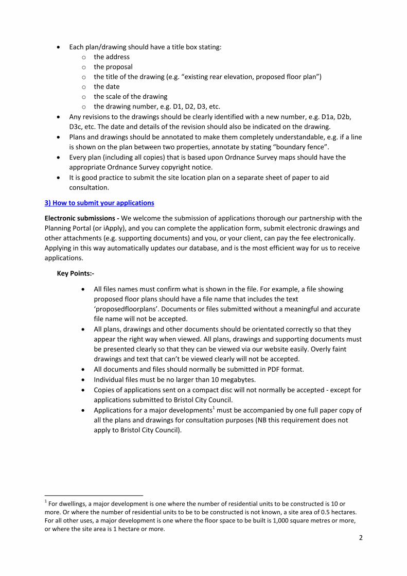
Each plan/drawing should have a title box stating:
o the address
o the proposal
o the title of the drawing (e.g. “existing rear elevation, proposed floor plan”)
o the date
o the scale of the drawing
o the drawing number, e.g. D1, D2, D3, etc.
Any revisions to the drawings should be clearly identified with a new number, e.g. D1a, D2b,
D3c, etc. The date and details of the revision should also be indicated on the drawing.
Plans and drawings should be annotated to make them completely understandable, e.g. if a line
is shown on the plan between two properties, annotate by stating “boundary fence”.
Every plan (including all copies) that is based upon Ordnance Survey maps should have the
appropriate Ordnance Survey copyright notice.
It is good practice to submit the site location plan on a separate sheet of paper to aid
consultation.
3) How to submit your applications
Electronic submissions - We welcome the submission of applications thorough our partnership with the
Planning Portal (or iApply), and you can complete the application form, submit electronic drawings and
other attachments (e.g. supporting documents) and you, or your client, can pay the fee electronically.
Applying in this way automatically updates our database, and is the most efficient way for us to receive
applications.
Key Points:-
All files names must confirm what is shown in the file. For example, a file showing
proposed floor plans should have a file name that includes the text
‘proposedfloorplans’. Documents or files submitted without a meaningful and accurate
file name will not be accepted.
All plans, drawings and other documents should be orientated correctly so that they
appear the right way when viewed. All plans, drawings and supporting documents must
be presented clearly so that they can be viewed via our website easily. Overly faint
drawings and text that can’t be viewed clearly will not be accepted.
All documents and files should normally be submitted in PDF format.
Individual files must be no larger than 10 megabytes.
Copies of applications sent on a compact disc will not normally be accepted - except for
applications submitted to Bristol City Council.
Applications for a major developments1 must be accompanied by one full paper copy of
all the plans and drawings for consultation purposes (NB this requirement does not
apply to Bristol City Council).
1 For dwellings, a major development is one where the number of residential units to be constructed is 10 or
more. Or where the number of residential units to be to be constructed is not known, a site area of 0.5 hectares. For all other uses, a major development is one where the floor space to be built is 1,000 square metres or more, or where the site area is 1 hectare or more.
3
Paper Submissions – You are able to submit your application on paper, and if you do this you should
send the completed application to the address at the end of the document.
Key Points:-
If you send an application to Bristol, South Gloucestershire or Bath and North East
Somerset council in paper format you only need to provide one copy of the plans and any
accompanying documents, such as any supporting documents and the application form.
Two copies are required when sending applications to North Somerset Council.
All plans and drawings must be presented clearly so that when scanned they can be viewed
via our website easily. For example overly faint lines and annotations that can’t be viewed
clearly will not be accepted.
Plans should normally be submitted separately, i.e. not in a binder
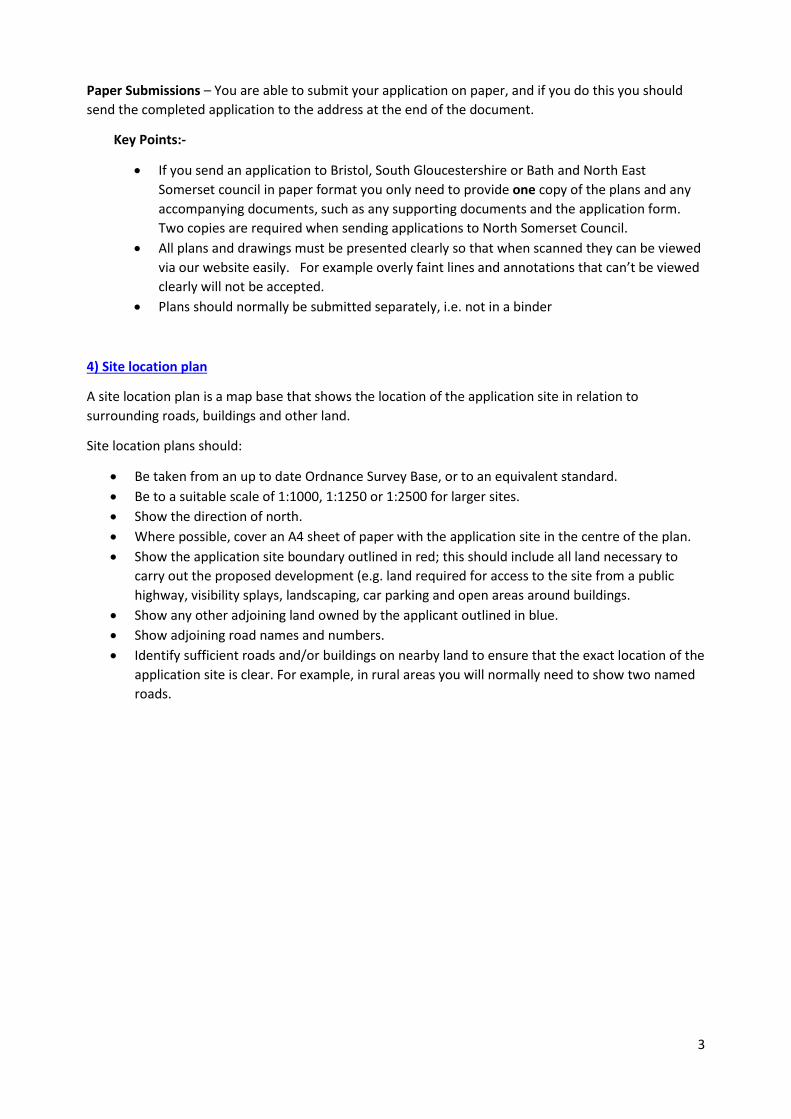
4) Site location plan
A site location plan is a map base that shows the location of the application site in relation to
surrounding roads, buildings and other land.
Site location plans should:
Be taken from an up to date Ordnance Survey Base, or to an equivalent standard.
Be to a suitable scale of 1:1000, 1:1250 or 1:2500 for larger sites.
Show the direction of north.
Where possible, cover an A4 sheet of paper with the application site in the centre of the plan.
Show the application site boundary outlined in red; this should include all land necessary to
carry out the proposed development (e.g. land required for access to the site from a public
highway, visibility splays, landscaping, car parking and open areas around buildings.
Show any other adjoining land owned by the applicant outlined in blue.
Show adjoining road names and numbers.
Identify sufficient roads and/or buildings on nearby land to ensure that the exact location of the
application site is clear. For example, in rural areas you will normally need to show two named
roads.
4
Image 1: Site location plan (for illustrative purposes only)
5
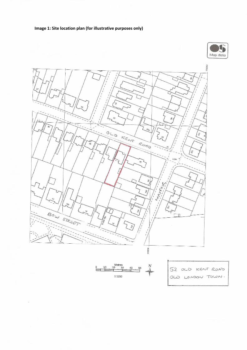
5) Site layout plan (sometimes called a block plan)
A site layout plan shows a detailed layout of the whole site and the relationship of the proposed works
with the boundary of the property, nearby roads and neighbouring buildings.
Most applications should include an existing site layout plan and a proposed site layout plan. For simple
applications the existing and proposed site can be combined and shown on one plan so long as what is
existing, what is proposed and what is to be demolished is highlighted and annotated clearly.
Site layout plans should:
Be to a scale of 1:200 or 1:500
Show the proposed development, all existing buildings and structures, the garden and other
open areas.
Show proposed buildings shaded.
Show the position and size of existing and proposed hard surfaced areas eg parking spaces,
turning areas, paths, etc.
Show the whole of the boundary of the property, indicating the position and height of all
boundary walls and fences.
Identify any buildings to be demolished
Include details of all trees, e.g. position, spread and species (eg oak, ash, etc).
Identify trees proposed for felling.
Show all roads/footpaths/public rights of way adjoining the site.
Show all existing buildings and structures on land adjoining the application site2
Show the direction of north.
2 Buildings and structures on land adjoining the site must be clearly shown unless the applicant has demonstrated that these would NOT
influence or be affected by the proposed development
6
Image 2: Site layout plan (for illustrative purposes only)
7
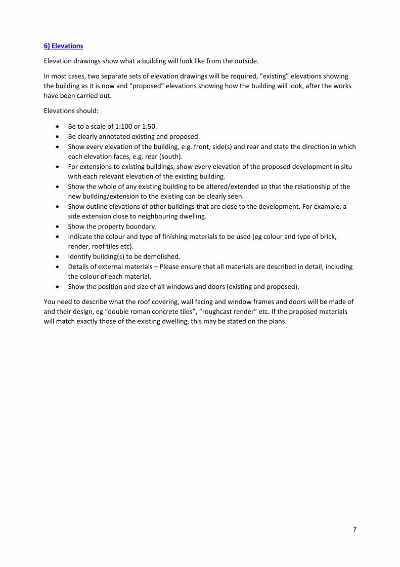
6) Elevations
Elevation drawings show what a building will look like from the outside.
In most cases, two separate sets of elevation drawings will be required, “existing” elevations showing
the building as it is now and “proposed” elevations showing how the building will look, after the works
have been carried out.
Elevations should:
Be to a scale of 1:100 or 1:50.
Be clearly annotated existing and proposed.
Show every elevation of the building, e.g. front, side(s) and rear and state the direction in which
each elevation faces, e.g. rear (south).
For extensions to existing buildings, show every elevation of the proposed development in situ
with each relevant elevation of the existing building.
Show the whole of any existing building to be altered/extended so that the relationship of the
new building/extension to the existing can be clearly seen.
Show outline elevations of other buildings that are close to the development. For example, a
side extension close to neighbouring dwelling.
Show the property boundary.
Indicate the colour and type of finishing materials to be used (eg colour and type of brick,
render, roof tiles etc).
Identify building(s) to be demolished.
Details of external materials – Please ensure that all materials are described in detail, including
the colour of each material.
Show the position and size of all windows and doors (existing and proposed).
You need to describe what the roof covering, wall facing and window frames and doors will be made of
and their design, eg “double roman concrete tiles”, “roughcast render” etc. If the proposed materials
will match exactly those of the existing dwelling, this may be stated on the plans.
8
Image 3: Elevations (for illustrative purposes only)
9
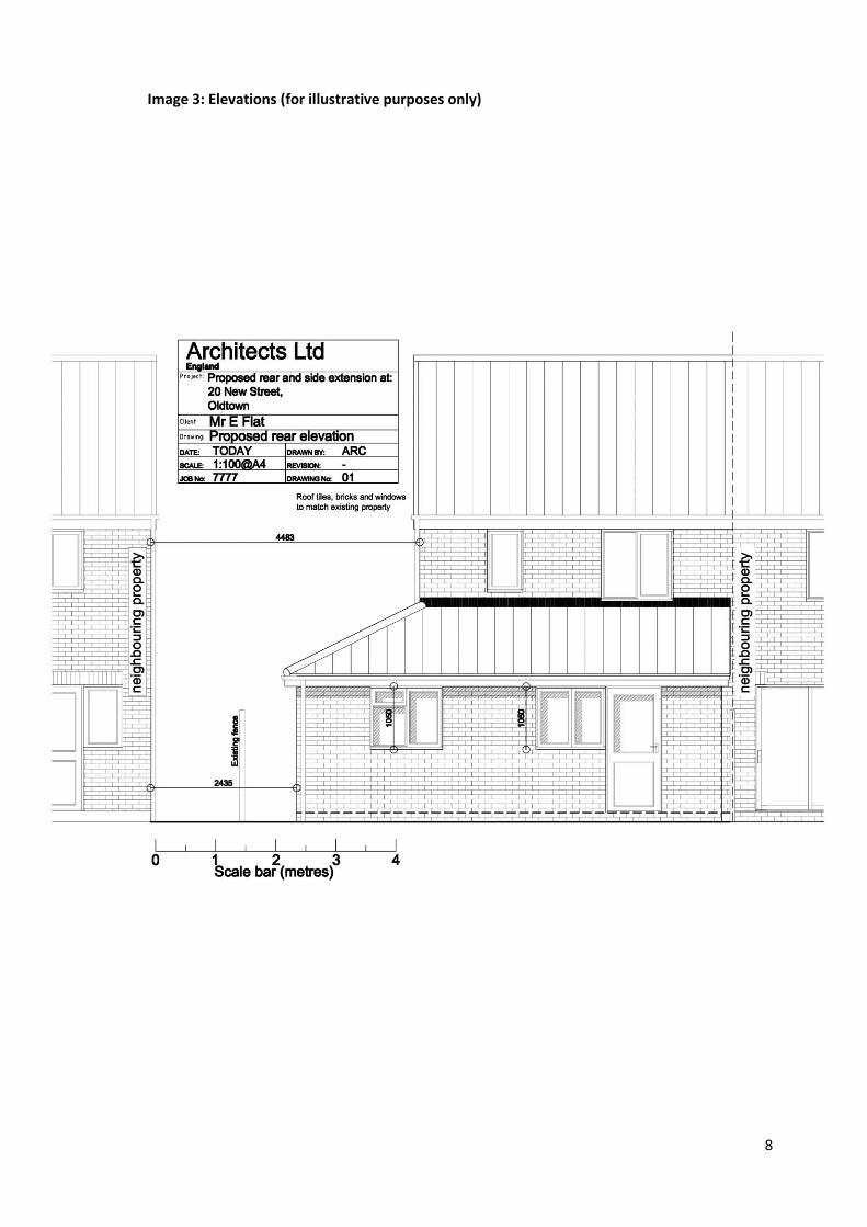
7) Floor plans
Floor plans show the layout of the building.
In most cases, two separate sets of floor plans will be required: “existing” floor plans showing the
building as it is now and “proposed” floor plans showing how the building will look, after the works
have been carried out.
Floor plans should:
Be to a scale of 1:100 or 1:50.
Be clearly annotated existing and proposed.
Show all relevant floor levels of the building(s) being constructed, altered or extended, in
relation to the remainder of the building.
Clearly state the use of each room and include position of windows, doors, walls and partitions.
Clearly label each floor.
Clearly label the primary use of each room
Identify anything to be demolished.
10
Image 4: Floor plans (for illustrative purposes only)
11
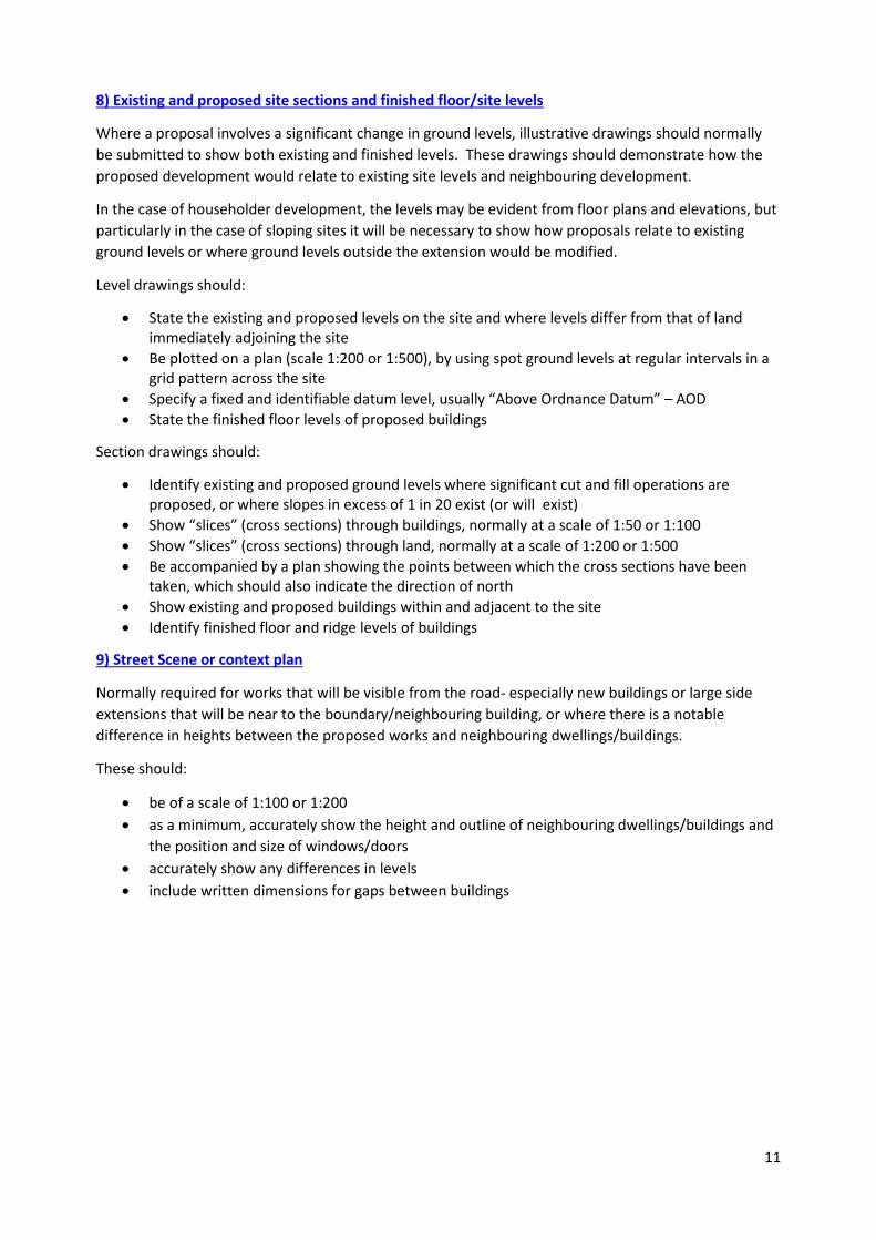
8) Existing and proposed site sections and finished floor/site levels
Where a proposal involves a significant change in ground levels, illustrative drawings should normally
be submitted to show both existing and finished levels. These drawings should demonstrate how the
proposed development would relate to existing site levels and neighbouring development.
In the case of householder development, the levels may be evident from floor plans and elevations, but
particularly in the case of sloping sites it will be necessary to show how proposals relate to existing
ground levels or where ground levels outside the extension would be modified.
Level drawings should:
State the existing and proposed levels on the site and where levels differ from that of land immediately adjoining the site
Be plotted on a plan (scale 1:200 or 1:500), by using spot ground levels at regular intervals in a grid pattern across the site
Specify a fixed and identifiable datum level, usually “Above Ordnance Datum” – AOD
State the finished floor levels of proposed buildings
Section drawings should:
Identify existing and proposed ground levels where significant cut and fill operations are proposed, or where slopes in excess of 1 in 20 exist (or will exist)
Show “slices” (cross sections) through buildings, normally at a scale of 1:50 or 1:100
Show “slices” (cross sections) through land, normally at a scale of 1:200 or 1:500
Be accompanied by a plan showing the points between which the cross sections have been taken, which should also indicate the direction of north
Show existing and proposed buildings within and adjacent to the site
Identify finished floor and ridge levels of buildings
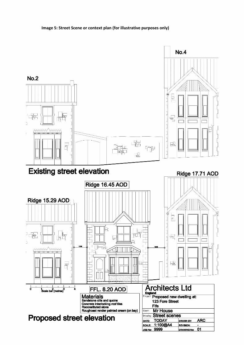
9) Street Scene or context plan
Normally required for works that will be visible from the road- especially new buildings or large side
extensions that will be near to the boundary/neighbouring building, or where there is a notable
difference in heights between the proposed works and neighbouring dwellings/buildings.
These should:
be of a scale of 1:100 or 1:200
as a minimum, accurately show the height and outline of neighbouring dwellings/buildings and
the position and size of windows/doors
accurately show any differences in levels
include written dimensions for gaps between buildings
12
Image 5: Street Scene or context plan (for illustrative purposes only)
13
10) Roof plans
These should be drawn to a scale of 1:50 or 1:100 and is used to show the shape of the roof particularly
when development includes changes to its appearance and shape. Show the position of all ridges,
valleys, dormer windows, roof lights and other features, such as chimneys or raised parapets. Details
such as the roofing material and their location are typically specified on the roof plan.
11) Landscaping
Landscaping plans/details
Landscaping plans should accurately show:
The position and spread of the existing trees.
Details of any trees to be retained and measures to be taken to protect the trees.
The species of the trees and details of their condition.
An indication of which, if any, are to be felled.
Details of the size, species and positions of trees to be planted and boundary treatments.
Landscaping schemes
In many instances the submission of landscaping details can be a condition of the planning permission.
In some cases specialist detail, for example a tree survey or detailed design may be required when
submitting landscaping schemes. It is recommended that you discuss with officers the scope and detail
required prior to submission.
12) Joinery drawings and details
These should be accurately drawn and comply with the following standards:
Drawn at a scale of 1:10.
When traditional features are being replaced - existing elevations are required drawn at a scale
of 1:10.
Proposed joinery sections are required and should be drawn at a scale of 1:1 or 1:2.
Proposed joinery sections for windows and doors should include the wall in which they are
mounted to show the depth of reveal
When traditional features are being replaced - existing joinery sections are required drawn at a
scale of 1:1 or 1:2.
Details of the proposed joinery materials are required. For example: “sustainably sourced hard
wood stained with…”
13) Photographs and photomontages
These should be clearly labelled on the front of each image (not the back) with a title that explains what
is shown and the exact location from which it was taken. This is best achieved by showing the location
on an associated map.
14
14) Contact details
LPA Postal Address Email address/Planning Web Page Telephone
Bath & North
East Somerset
Council
Lewis House,
Manvers St, Bath
BA1 1JG
[email protected] 01225 394041
(option 5)
Bristol City
Council
Planning Services
(CH), PO Box 3176,
Bristol BS3 9FS
Web Site: Make a Planning application
0117 9223000
North Somerset
Council
Town Hall,
Walliscote Grove
Road, Weston-
super-Mare BS23
1UJ
www.n-somerset.gov.uk/contactplanning 01275 888811
15) Acknowledgements
The example drawings were provided by Graham Moir Associates