FORCES STRUCTURES DESCRIBING STRUCTURES STRESS, FATIGUE, FAILURE Grab Bag 10 20 30 40 50.
Upload
tarak-a-positiveCategory
view
3download
0description
A
SEMINAR REPORT
on
ADEQUACY OF PROVISIONS FOR MINIMUM SEATING LENGHT OF RAILWAY STEEL BRIDGES
Submitted in partial fulfilment of the
Requirements for the award of the degreeof
MASTER OF TECHNOLOGYin
EARTHQUAKE ENGINEERING(With Specialization in Structural Dynamics)
Submitted by
KANTUBHUKTA TARAKESWARA RAO
M.Tech (I Year)Under the Guidance of
Mr.Ashok.D.PANDEY
DEPARTMENT OF EARTHQUAKE ENGINEERINGINDIAN INSTITUTE OF TECHNOLOGY ROORKEE
ROORKEE-247667, INDIA MAY, 2015
i
CANDIDATE’S DECLARATION
I hereby declare that work which is being presented in this seminar report entitled, “Adequacy Of
Provisions For Minimum Seating Length Of Railway Steel Bridges ”, in the partial fulfilment of the requirements for the award of the degree of MASTER OF TECHNOLOGY in EARTHQUAKE ENGINEERING, with specialization in STRUCTURAL DYNAMICS, submitted in the Department of Earthquake Engineering, Indian Institute of Technology, Roorkee is an authentic record of my own work carried during the period from January 2015 to May 2015 under the supervision of Dr. A.D.Pandey, Professor, Department of Earthquake Engineering, IIT Roorkee.
The matter embodied in this Dissertation has not been submitted by me for the award of any other degree
or diploma of this Institute or any other University/Institute.
Place: Roorkee
Date:14/11/2015 (K TARAKESWARA RAO)
CERTIFICATE
This is to certify that the above statement made by the candidate is correct to the best of my knowledge.
(Dr. A.D.PANEY)
Place: Roorkee ProfessorDate: 14-11-2015 Dept. of Earthquake Engineering Indian Institute of Technology Roorkee Roorkee -247667
ACKNOWLEDGEMENT
ii
I wish to express my deep sense of gratitude and indebtedness to my learned and enlightened guide Dr.
A.D.PANDEY, Professor, Department of Earthquake Engineering, Indian Institute of Technology,
Roorkee, for his instinctive and careful guidance and continued encouragement in the completion of this
Seminar Report.
I am extremely grateful to my family and to my friends for their endless support and encouragement, and
for always believing that I can succeed in my endeavours.
I am highly indebted to all other members of the Department for their continuous support, valuable
suggestions and encouragement throughout this Report. I thank all members, who helped directly or
indirectly in bringing this report to this present form.
(K TARAKESWARA RAO)
CONTENTS
iii

Candidate’s Declaration ii
Acknowledgement iii
Contents iv
List of Figures v
1.Introduction1.1 1
1.2 Necessity ofForensic engineering1
1.3 The Role of Forensic Engineering2
1.4 When to start?6
1.5 Source of Information 6
1.6 Back analysis, Re-building, Simulation, and Re-enactment 8
1.7Report of Investigation 9
1.8Recommendations 9
2. Failures and Remedies2.1 Types of Failures12
2.2 Post-mortem of Failures14
2.3 Study of modes of Failures 16
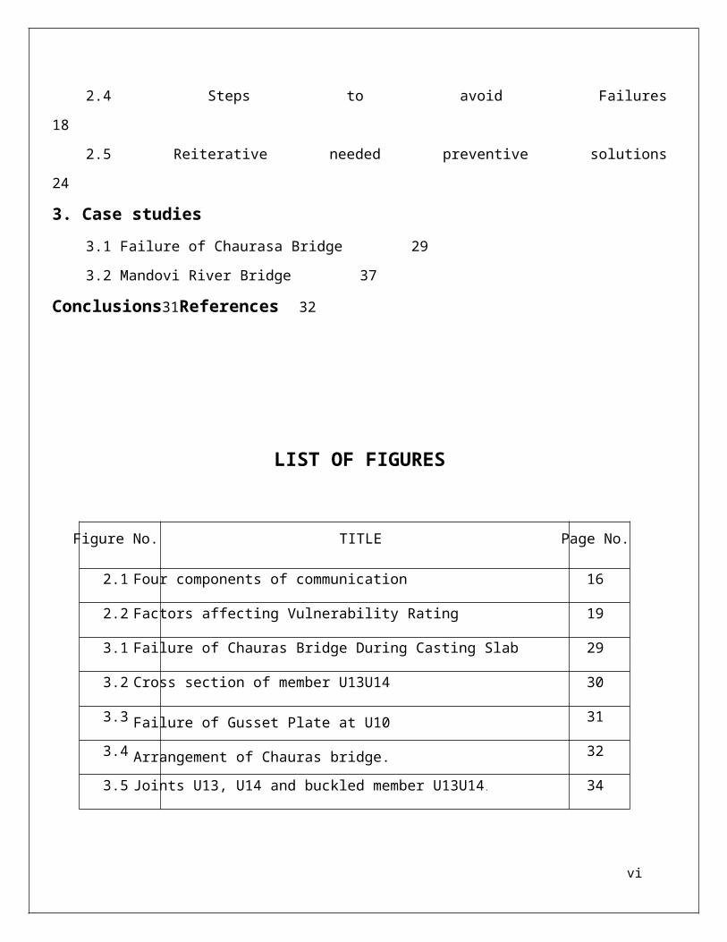
2.4 Steps to avoid Failures 18
2.5 Reiterative needed preventive solutions 24
3. Case studies3.1 Failure of Chaurasa Bridge 29
3.2 Mandovi River Bridge 37
Conclusions31References 32
LIST OF FIGURES
iv
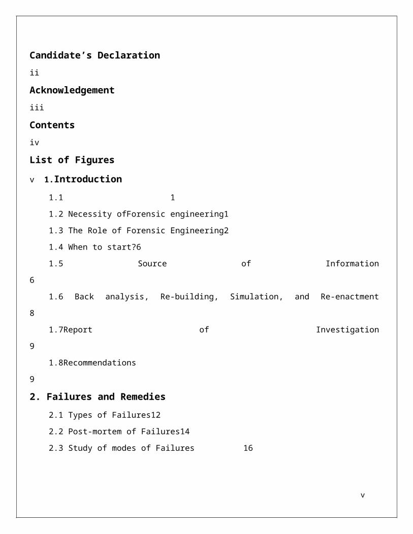
Figure No. TITLE Page No.
2.1 Four components of communication 16
2.2 Factors affecting Vulnerability Rating 19
3.1 Failure of Chauras Bridge During Casting Slab 29
3.2 Cross section of member U13U14 30
3.3 Failure of Gusset Plate at U10 31
3.4 Arrangement of Chauras bridge. 32
3.5 Joints U13, U14 and buckled member U13U14. 34
v
Chapter -1
INTRODUCTION
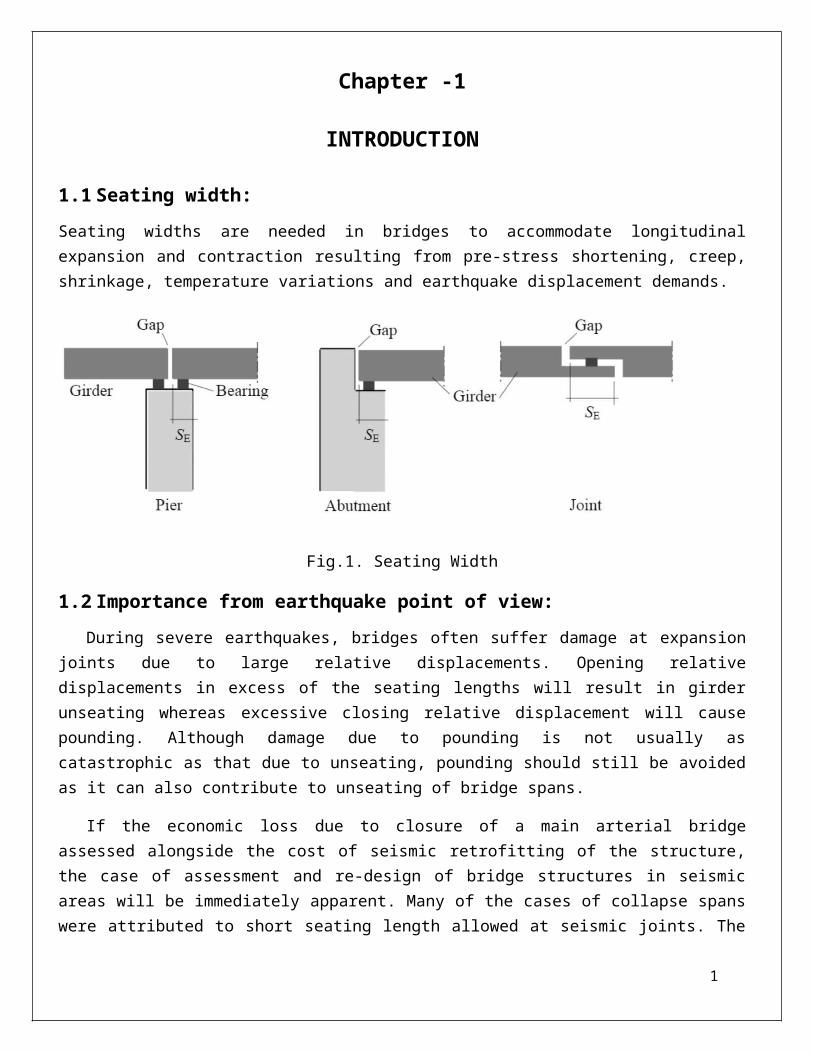
1.1 Seating width:
Seating widths are needed in bridges to accommodate longitudinal expansion and contraction resulting from pre-stress shortening, creep, shrinkage, temperature variations and earthquake displacement demands.
Fig.1. Seating Width
1.2 Importance from earthquake point of view:
During severe earthquakes, bridges often suffer damage at expansion joints due to large relative displacements. Opening relative displacements in excess of the seating lengths will result in girder unseating whereas excessive closing relative displacement will cause pounding. Although damage due to pounding is not usually as catastrophic as that due to unseating, pounding should still be avoided as it can also contribute to unseating of bridge spans.
If the economic loss due to closure of a main arterial bridge assessed alongside the cost of seismic retrofitting of the structure, the case of assessment and re-design of bridge structures in seismic areas will be immediately apparent. Many of the cases of collapse spans were attributed to short seating length allowed at seismic joints. The cost of design and installation of restrainers would have been a very small fraction of the direct cost of repair and an even smaller proportion of the total cost including business interruption and loss of revenue.
A direct consequences of under estimating seismic displacements, which were based on elastic theory, gross section stiffness, and low lateral force levels, was that seating lengths provided at movement joints were unrealistically short, and lateral separations between adjacent structures were typically inadequate, resulting in pounding or unseating.
1

1.3 Reasons for Unseating:
1) Adjacent frames separated by movement joints may move out of phase, increasing the relative displacement across the joint
2) Bridges often comprises a series of simple spans supported on bents. These spans are prone to being toppled from their supporting substructure either due to shaking or differential support movement associated with ground deformation.
3) Relative displacements arise from different dynamic properties of adjacent structures, spatial variation of ground motions and soil-structure interaction. Most current bridge design codes tend to neglect the effects of spatial variation of ground motions. it is found that the spatial variation of the ground motions is common especially for long bridges.
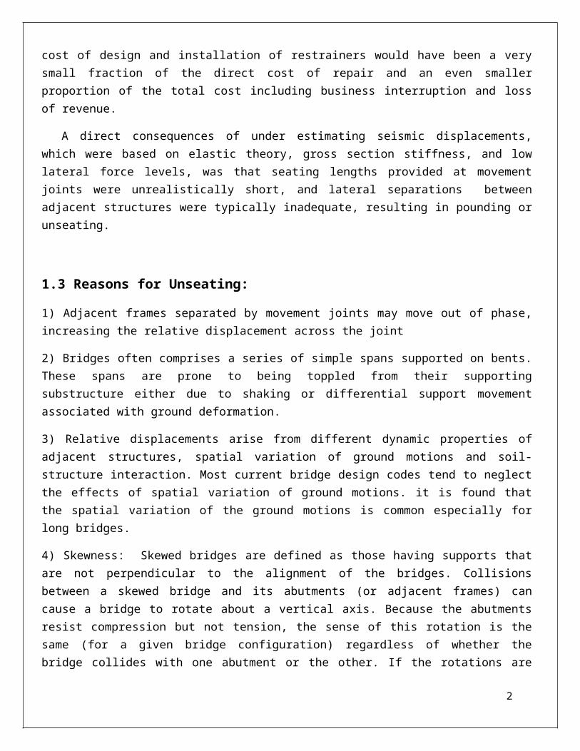
4) Skewness: Skewed bridges are defined as those having supports that are not perpendicular to the alignment of the bridges. Collisions between a skewed bridge and its abutments (or adjacent frames) can cause a bridge to rotate about a vertical axis. Because the abutments resist compression but not tension, the sense of this rotation is the same (for a given bridge configuration) regardless of whether the bridge collides with one abutment or the other. If the rotations are large and seat lengths small a bridge can come unseated at the acute corners of the decks.
It has been observed that skewed spans develop large displacements than right spans, as a consequence of tendency for the skew span to rotate in the direction of decreasing skew, thus tending to drop off the supports at the acute corners. This behavior is due to combination of longitudinal and transverse response and is illustrated schematically in the following fig:2
Fig.2. Effect of Skewness on Unseating
2
1.4 Prevention of Bridge Unseating :
1)Through setting “structural fuse” to attain change of multi-level control state and avoid unrepairable damage of important components due to application of restrainer realizing damage reduction philosophy.
2)Restrainers: different retrofit programs and unseating prevention devices have been generally applied to prevent unseating of span for existing and new bridges in Japan and Chinese Taiwan.
The connection mode between girder and pier of bridges is usually applied in US and the connection mode between adjacent girders of bridges is usually applied in Japan. The connection mode between girder and pier of bridges can reduce the relative displacement between upper part structure and lower part structure effectively, however, the seismic load transferred from upper part structure into pier due to application of girder-pier restrainers may aggravate the damage of lower part structure leading to un-repairable damage or even collapse of bridges. The connection mode between adjacent vibration spans of bridges does not basically change the interaction behavior between upper part structure and lower part structure; therefore, the excessive relative displacement between span and pier can’t be controlled effectively.
3) Through passive energy dissipation mechanism to reduce the structural earthquake responses realizing seismic energy dissipation design philosophy.
4) According to different earthquake action levels to determine different performance control objectives realizing multi-failure criteria.
5) By providing adequate seating length.
3
Chapter-2DIFFERENT CODAL RECOMMENDATIONS FOR MINIMUM SEATING
LENGTH
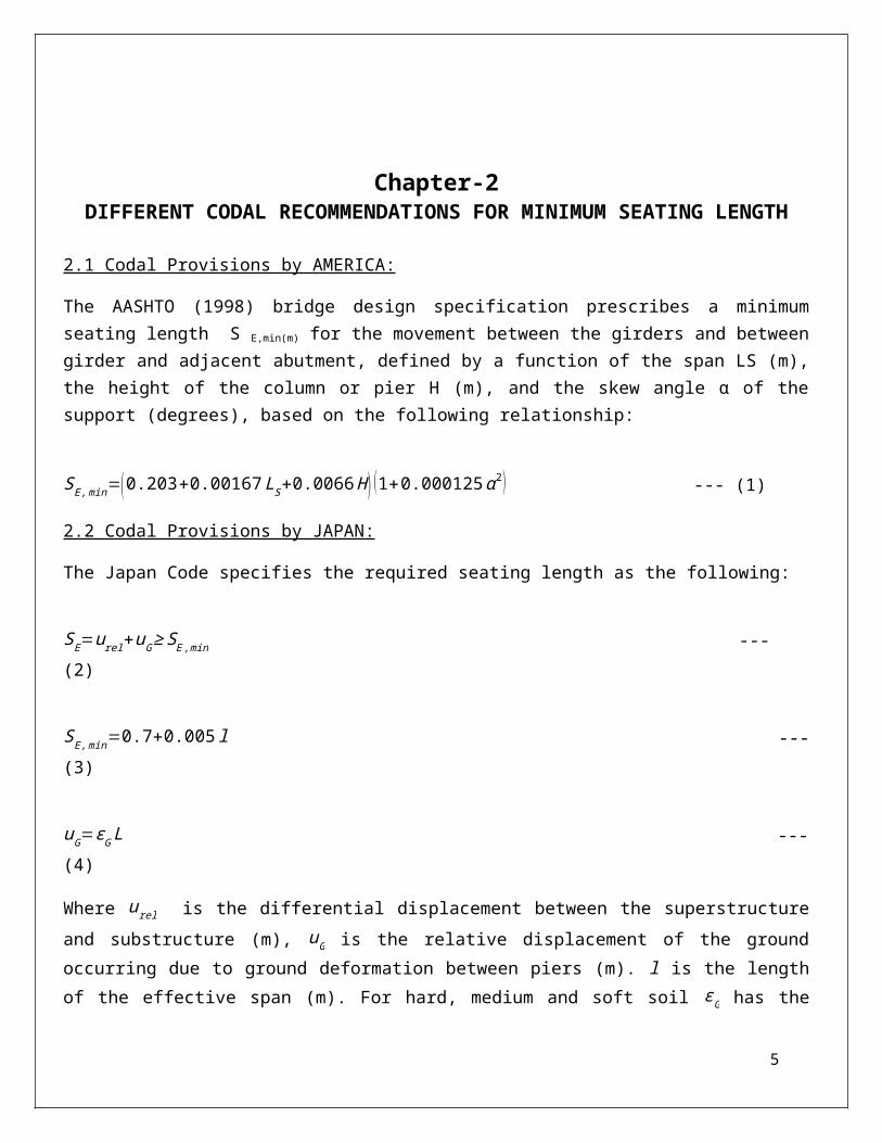
2.1 Codal Provisions by AMERICA:
The AASHTO (1998) bridge design specification prescribes a minimum seating length S E,min(m) for the movement between the girders and between girder and adjacent abutment, defined by a function of the span LS (m), the height of the column or pier H (m), and the skew angle α of the support (degrees), based on the following relationship:
SE,min=( 0.203+0.00167 LS+0.0066 H ) (1+0.000125 α 2 ) --- (1)
2.2 Codal Provisions by JAPAN:
The Japan Code specifies the required seating length as the following:
SE=urel+uG ≥ S E ,min --- (2)
SE ,min=0.7+0.005 l --- (3)
uG=εG L --- (4)
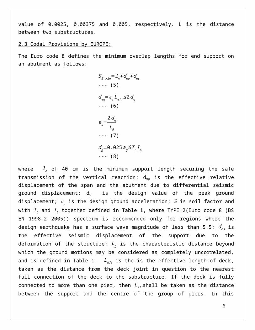
Where urel is the differential displacement between the superstructure and substructure (m), uG is the relative displacement of the ground occurring due to ground deformation between piers (m). l is the length of the effective span (m). For hard, medium and soft soil ε G has the value of 0.0025, 0.00375 and 0.005, respectively. L is the distance between two substructures.
2.3 Codal Provisions by EUROPE:
The Euro code 8 defines the minimum overlap lengths for end support on an abutment as follows:
SE,min=lm+deg+des --- (5)
deg=ε s Leff ≤ 2 dg --- (6)
ε s=2 dg
Lg --- (7)
d g=0.025ag ST CT D --- (8)
where lm of 40 cm is the minimum support length securing the safe transmission of the vertical reaction; deg is the effective relative displacement of the span and the abutment due to differential seismic ground displacement; dg is the design value of the peak ground displacement; ag is the design ground acceleration; S is soil factor and with T C and T D together defined in Table 1, where TYPE 2(Euro code 8 (BS EN 1998-2 2005)) spectrum is recommended only for regions where the design earthquake has a surface wave
4
magnitude of less than 5.5; des is the effective seismic displacement of the support due to the deformation of the structure; Lg is the characteristic distance beyond which the ground motions may be considered as completely uncorrelated, and is defined in Table 1. Leff is the is the effective length of deck, taken as the distance from the deck joint in question to the nearest full connection of the deck to the substructure. If the deck is fully connected to more than one pier, then Leff shall be taken as the distance between the support and the centre of the group of piers. In this context, ‘full connection’ means a connection of the deck or deck section to a substructure member, either monolithically or through fixed bearing, seismic links, or shock transmission units.
case S T C (s ) T D (s) Lg(m)
Spectrum type 1 2 1 2 1 2 1 and 2
Soil class A 1 1 0.4 0.25 2 1.2 600
Soil class A 1.2 1.35 0.5 0.25 2 1.2 500
Soil class A 1.15 1.5 0.6 0.25 2 1.2 400
Soil class A 1.35 1.8 0.8 0.3 2 1.2 300
Soil class A 1.4 1.6 0.5 0.25 2 1.2 500
Table1. Recommended values of the parameters for TYPR 1 and TYPE 2 elastic response spectrum (reproduced from Euro code 8 (BS EN 1998-2 2005)).
2.4 Codal Provisions by NEWZELAND:
The NZTA Bridge manual specifies the provisions for the minimum seating length to prevent span loss. The provision, in the absence of a linkage system is as follows:
SE ,min=2.0E+0 .1≥ 0.4 m --- (9)
Where SE ,min is the minimum seating length; E is relative movement between span and support. For more details, please refer to the NZTA Bridge manual, Section 5.6.2.
2.5 Comparison Among Codes:
As can be seen from Equation 1, the AASHTO code suggests the minimum seating length by a function of only the span length and the pier height. It does not consider the influences of the ground motions and dynamic properties of the bridge. It implies that no matter how significant the earthquake is and whether the bridge is stiff or flexible, as long as the bridge has the same span and pier height, the required seating length will be the same. In reality, this is not the case. Therefore, the recommendation of minimum seating length by the AASHTO is less holistic. The current Japan design specification considers
5
the influence of the frequency ratio of the neighbouring structures and also implicitly accounts for the effect of spatially varying ground displacements. However, according to the research by Chouw and Hao (2006), it can still underestimate the necessary seating length, especially when the adjacent structure is more flexible. Euro code 8 is currently the only seismic code worldwide that provides a clear and detailed framework for considering the effect of spatial variation of ground motions in bridge design. In the calculation of minimum overlap lengths, the relative displacement of the adjacent structures accounting for spatial variation is incorporated in Equation 9.
IITK-RDSO guidelines for railway b ridges in INDIA:
The widths of seating SE(in mm) at supports measured normal to the face of the abutment/pier/pedestal of bearings/restrained portion of superstructure from the closest end of the girder shall be the larger of the following:
1.4 times the calculated displacement under the maximum elastic seismic forces estimated as per Clauses 9.2 or 10.3, to account for uncertainty in deflection calculation; and (b)
the value specified below:
SE={ 300+1.5 LS+6 H for seismic zones II∧III−−(10)500+2.5 LS+10 H for seismic zones IV ∧V −−(11)
Where, LS is Length (in meters) of the superstructure to the adjacent expansion joint or to the end of superstructure. In case of bearings under suspended spans, it is sum of the lengths of the two adjacent portions of the superstructure. In case of single span bridges, it is equal to the length of the superstructure.
For bearings at abutments, H is the average height (in meters) of all columns supporting the superstructure to the next expansion joint. It is equal to zero for single span bridges. For bearings at columns or piers, Hp is the height (in meters) of column or pier.
For bearings under suspended spans, Hp is the average height (in meters) of the two adjacent columns or piers.
Graphical representation of seating widths is shown in Fig. 8.
6
Examples:
Such damage was observed in the 1999 Ji-Ji earthquake (Hamada et al. 1999), the 2008 Wenchuan earthquake (Lin et al. 2008) and the 2010 Chile earthquake (Arias and Buckle 2010).
BRIDGE MODELS2 Girder Bridges with Effective Spans of 13.926m and 25.6 m subjected to two different loadings i.e. 25T Loading and 32.5T Loading cases have been used. The sectional details are given below. The sectional details has been collected from RDSO(Reaserch Design and Standard Organisation)(Ministry of Railways),Lucknow,India.13.1m Span Plate Girder Bridge (25 Tloading):
Conclusions
7
References
1. Mohiuddin A. Khan (2010),“Bridge and Highway Structure Rehabilitation and Repair”. The McGraw-Hill Companies, Inc
2. Dr.N.Subramaniam and Prof.A.R.Santhakumar,“Learning from failures: Case Studies”INstite for Steel Development And Growth(INSDAG)
3. N. Krishnamurthy and Dr. Natarajan“Forensic Engineering in Structural Design and Construction”published in Structural Engineers World Congress 2007, 2-7 Nov. 2007, Bangalore, India.
4. Harshad Subhashrao Birajdar, Pabitra Ranjan Maiti, Pramod Kumar Singh “Failure of Chauras bridge” paper published inELSEVIER Journal on 2014.
8